EP1728985A1 - Connection structure of multi-channel tube with branching tube and connection method therefor - Google Patents
Connection structure of multi-channel tube with branching tube and connection method therefor Download PDFInfo
- Publication number
- EP1728985A1 EP1728985A1 EP06011021A EP06011021A EP1728985A1 EP 1728985 A1 EP1728985 A1 EP 1728985A1 EP 06011021 A EP06011021 A EP 06011021A EP 06011021 A EP06011021 A EP 06011021A EP 1728985 A1 EP1728985 A1 EP 1728985A1
- Authority
- EP
- European Patent Office
- Prior art keywords
- tube
- end portion
- branch
- branch tubes
- expanded
- Prior art date
- Legal status (The legal status is an assumption and is not a legal conclusion. Google has not performed a legal analysis and makes no representation as to the accuracy of the status listed.)
- Granted
Links
Images


Classifications
-
- F—MECHANICAL ENGINEERING; LIGHTING; HEATING; WEAPONS; BLASTING
- F16—ENGINEERING ELEMENTS AND UNITS; GENERAL MEASURES FOR PRODUCING AND MAINTAINING EFFECTIVE FUNCTIONING OF MACHINES OR INSTALLATIONS; THERMAL INSULATION IN GENERAL
- F16L—PIPES; JOINTS OR FITTINGS FOR PIPES; SUPPORTS FOR PIPES, CABLES OR PROTECTIVE TUBING; MEANS FOR THERMAL INSULATION IN GENERAL
- F16L39/00—Joints or fittings for double-walled or multi-channel pipes or pipe assemblies
-
- B—PERFORMING OPERATIONS; TRANSPORTING
- B21—MECHANICAL METAL-WORKING WITHOUT ESSENTIALLY REMOVING MATERIAL; PUNCHING METAL
- B21C—MANUFACTURE OF METAL SHEETS, WIRE, RODS, TUBES OR PROFILES, OTHERWISE THAN BY ROLLING; AUXILIARY OPERATIONS USED IN CONNECTION WITH METAL-WORKING WITHOUT ESSENTIALLY REMOVING MATERIAL
- B21C37/00—Manufacture of metal sheets, bars, wire, tubes or like semi-manufactured products, not otherwise provided for; Manufacture of tubes of special shape
- B21C37/06—Manufacture of metal sheets, bars, wire, tubes or like semi-manufactured products, not otherwise provided for; Manufacture of tubes of special shape of tubes or metal hoses; Combined procedures for making tubes, e.g. for making multi-wall tubes
- B21C37/15—Making tubes of special shape; Making tube fittings
- B21C37/151—Making tubes with multiple passages
-
- B—PERFORMING OPERATIONS; TRANSPORTING
- B21—MECHANICAL METAL-WORKING WITHOUT ESSENTIALLY REMOVING MATERIAL; PUNCHING METAL
- B21C—MANUFACTURE OF METAL SHEETS, WIRE, RODS, TUBES OR PROFILES, OTHERWISE THAN BY ROLLING; AUXILIARY OPERATIONS USED IN CONNECTION WITH METAL-WORKING WITHOUT ESSENTIALLY REMOVING MATERIAL
- B21C37/00—Manufacture of metal sheets, bars, wire, tubes or like semi-manufactured products, not otherwise provided for; Manufacture of tubes of special shape
- B21C37/06—Manufacture of metal sheets, bars, wire, tubes or like semi-manufactured products, not otherwise provided for; Manufacture of tubes of special shape of tubes or metal hoses; Combined procedures for making tubes, e.g. for making multi-wall tubes
- B21C37/15—Making tubes of special shape; Making tube fittings
- B21C37/28—Making tube fittings for connecting pipes, e.g. U-pieces
-
- B—PERFORMING OPERATIONS; TRANSPORTING
- B23—MACHINE TOOLS; METAL-WORKING NOT OTHERWISE PROVIDED FOR
- B23K—SOLDERING OR UNSOLDERING; WELDING; CLADDING OR PLATING BY SOLDERING OR WELDING; CUTTING BY APPLYING HEAT LOCALLY, e.g. FLAME CUTTING; WORKING BY LASER BEAM
- B23K1/00—Soldering, e.g. brazing, or unsoldering
- B23K1/0008—Soldering, e.g. brazing, or unsoldering specially adapted for particular articles or work
-
- F—MECHANICAL ENGINEERING; LIGHTING; HEATING; WEAPONS; BLASTING
- F01—MACHINES OR ENGINES IN GENERAL; ENGINE PLANTS IN GENERAL; STEAM ENGINES
- F01N—GAS-FLOW SILENCERS OR EXHAUST APPARATUS FOR MACHINES OR ENGINES IN GENERAL; GAS-FLOW SILENCERS OR EXHAUST APPARATUS FOR INTERNAL COMBUSTION ENGINES
- F01N13/00—Exhaust or silencing apparatus characterised by constructional features ; Exhaust or silencing apparatus, or parts thereof, having pertinent characteristics not provided for in, or of interest apart from, groups F01N1/00 - F01N5/00, F01N9/00, F01N11/00
- F01N13/08—Other arrangements or adaptations of exhaust conduits
-
- F—MECHANICAL ENGINEERING; LIGHTING; HEATING; WEAPONS; BLASTING
- F01—MACHINES OR ENGINES IN GENERAL; ENGINE PLANTS IN GENERAL; STEAM ENGINES
- F01N—GAS-FLOW SILENCERS OR EXHAUST APPARATUS FOR MACHINES OR ENGINES IN GENERAL; GAS-FLOW SILENCERS OR EXHAUST APPARATUS FOR INTERNAL COMBUSTION ENGINES
- F01N13/00—Exhaust or silencing apparatus characterised by constructional features ; Exhaust or silencing apparatus, or parts thereof, having pertinent characteristics not provided for in, or of interest apart from, groups F01N1/00 - F01N5/00, F01N9/00, F01N11/00
- F01N13/18—Construction facilitating manufacture, assembly, or disassembly
- F01N13/1805—Fixing exhaust manifolds, exhaust pipes or pipe sections to each other, to engine or to vehicle body
-
- B—PERFORMING OPERATIONS; TRANSPORTING
- B23—MACHINE TOOLS; METAL-WORKING NOT OTHERWISE PROVIDED FOR
- B23K—SOLDERING OR UNSOLDERING; WELDING; CLADDING OR PLATING BY SOLDERING OR WELDING; CUTTING BY APPLYING HEAT LOCALLY, e.g. FLAME CUTTING; WORKING BY LASER BEAM
- B23K2101/00—Articles made by soldering, welding or cutting
- B23K2101/04—Tubular or hollow articles
- B23K2101/06—Tubes
-
- F—MECHANICAL ENGINEERING; LIGHTING; HEATING; WEAPONS; BLASTING
- F01—MACHINES OR ENGINES IN GENERAL; ENGINE PLANTS IN GENERAL; STEAM ENGINES
- F01N—GAS-FLOW SILENCERS OR EXHAUST APPARATUS FOR MACHINES OR ENGINES IN GENERAL; GAS-FLOW SILENCERS OR EXHAUST APPARATUS FOR INTERNAL COMBUSTION ENGINES
- F01N2450/00—Methods or apparatus for fitting, inserting or repairing different elements
- F01N2450/22—Methods or apparatus for fitting, inserting or repairing different elements by welding or brazing
-
- F—MECHANICAL ENGINEERING; LIGHTING; HEATING; WEAPONS; BLASTING
- F01—MACHINES OR ENGINES IN GENERAL; ENGINE PLANTS IN GENERAL; STEAM ENGINES
- F01N—GAS-FLOW SILENCERS OR EXHAUST APPARATUS FOR MACHINES OR ENGINES IN GENERAL; GAS-FLOW SILENCERS OR EXHAUST APPARATUS FOR INTERNAL COMBUSTION ENGINES
- F01N2470/00—Structure or shape of gas passages, pipes or tubes
- F01N2470/10—Tubes having non-circular cross section
Definitions
- the present invention relates to a tube having a multi-channel tube and branch tubes branching therefrom, a connection structure therefor and a method for forming and connection thereof.
- a branching tube is formed in accordance with the following procedure. First, a multi-channel tube which has a partition wall to partition the interior thereof into plural channels is provided. Second, branch tubes are respectively inserted into the channels of the multi-channel tube. Finally, brazing among the multi-channel tube and the branch tubes are carried out.
- a gap between the branch tubes is in general too narrow to carry out brazing since the gap is regulated only by a thickness of the partition wall provided in the interior of the multi-channel tube. Therefore failure of brazing among the multi-channel tube and the branch tubes, in particular, between the partition wall and each of the branch tubes is likely to happen.
- the branch tubes having relatively narrow inner flow channels as compared with the multi-channel tube are inserted in the channels, steps are formed in the channels and cross sectional areas thereof are reduced. They may cause turbulent or not smooth flow of the fluid and increase flow resistance.
- the present invention has been achieved in view of the above problem.
- a tube is provided with: a multi-channel tube including a partition wall to partition an interior of the multi-channel tube into plural channels and an expanded end portion; branch tubes inserted into the expanded end portion and respectively communicating with the channels; and clearances for being filled with brazing metal, the clearances being respectively kept between the multi-channel tube and each of the branch tubes.
- the branch tubes respectively include broadened end portions to be inserted into the expanded end portion of the multi-channel tube.
- the expanded end portion of the multi-channel tube has greater diameters in any radial directions except a direction along the partition wall than a diameter of a main portion of the multi-channel tube.
- the expanded end portion of the multi-channel tube is expanded only in a direction perpendicular to the direction along the partition wall.
- the multi-channel tube includes a reducer portion having larger diameters at a first end linking with the expanded end portion and reducing diameters toward a second end linking with the main portion of the multi-channel tube.
- each of end portions of the branch tubes, the end portions being inserted into the expanded end portion of the multi-channel tube is inclined with respect to a direction in which the end portion is inserted into the expanded end portion.
- branch tubes are treated with presswork to have offsets with respect to the multi-channel tube.
- cylindrical portions of the respective branch tubes are separated from each other in a state where the branch tubes are inserted into the expanded end portion.
- the branch tubes have offsets with respect to the multi-channel tube in a state where the branch tubes are inserted into the expanded end portion, wherein first end portions of the branch tubes, the first end portions being inserted into the expanded end portion, are parallel with second end portions of the branch tubes, and wherein the branch tubes have different lengths.
- a method for connection of a multi-channel tube with plural branch tubes is provided with steps of: expanding an end portion of the multi-channel tube; inserting the branch tubes into the expanded end portion, respectively; and brazing each of the branch tubes with the expanded end portion.
- the method is further provided with steps of:
- the step of broadening includes shaping the end portion of the branch tube to have an elliptic cross sectional shape.
- the step of clamping includes steps of inserting a mandrel into the broadened end portion of the branch tube, and bringing down an upper die to clamp the cylindrical portion of the branch tube between an upper clamp and a lower clamp and fix the branch tube by means of repulsive force of an elastic body of the upper die, and wherein the steps of press-working and forming are simultaneously carried out by forcing down the upper die to press down an upper mold onto the broadened end portion of the branch tube and press down a mandrel presser onto the mandrel so that the broadened end portion of the branch tube is formed to have the D-letter cross sectional shape and the branch tube is bent.
- the method is further provided with steps of: clamping a cylindrical portion of each branch tube, the cylindrical portion being apart from an end portion of the branch tube; press-working the end portion of the branch tube to have an offset with respect to the cylindrical portion of the branch tube; and forming the end portion of the branch tube to have a D-letter cross sectional shape.
- the method is further provided with a step of: broadening an end portion of each branch tube before the steps of clamping, press-working and forming.
- the method is further provided with a step of: broadening an end portion of each branch tube to have an elliptic cross sectional shape before the steps of clamping, press-working and forming.
- a multi-channel tube 1 is brazed with two branch tubes 10 to form a branching tube 9 as shown in Fig. 1.
- the multi-channel tube 1 is provided with an outer tubular portion 2 formed in a cylindrical shape and a partition wall 3, which partitions the interior of the multi-channel tube 1 into a pair of channels 4.
- the channels 4 are formed to be symmetrical and also have substantially the same cross sectional shape of a D-letter shape as shown in Figs. 3 through 5.
- the outer tubular portion 2 is opened at both longitudinal ends.
- One end portion of the multi-channel tube 1 is expanded in radial directions to have an expanded end portion 6 and a reducer portion 5 smoothly linking the expanded portion 6 with a main portion (un-expanded proximal portion) of the multi-channel tube 1.
- the reducer portion 5 has a tapered shape becoming thinner from one end linking with the expanded portion 6 toward the other end linking with the main portion. More specifically, the reducer portion 5 gradually reduces diameters from a diameter of the expanded portion 6 to a diameter of the main portion so as to smoothly linking therewith.
- a tip end of the expanded portion 6 is further expanded to be a flaring portion 7, which is used for supporting brazing metal before and during brazing.
- the partition wall 3, except for a portion around an end thereof, is tightly fixed with inner peripheries of the outer tubular portion 2 so as to keep air-tightness between both sides of the partition wall 3.
- the flaring portion 7 is separated from the partition wall 3 at the end thereof so as to have spaces 8 therebetween to allow fused brazing metal to pass therethrough.
- the branch tubes 10 have substantially the same shape and the same dimension except for end portions thereof as shown in Figs. 6A through 6C.
- the end portion of each branch tube 10 has a D-letter broadened portion 12 and a transitional portion 11.
- the D-letter broadened portion 12 is composed of a flat portion 12a for being contact with the partition wall 3 and an arc portion 12b for being contact with the outer tubular portion 2 and hence has a D-letter cross sectional shape. Exterior dimensions of the D-letter broadened portion 12 are greater than standard dimensions of each channel 4 and smaller than interior dimensions of the expanded portion 6.
- Each of the end portions of the branch tubes 10, which is inserted into the expanded end portion 6 of the multi-channel tube 1, is inclined with respect to an insertion direction in which the end portion is inserted into the expanded end portion 6.
- the flat portion 12a stepwise bulges outward from a straight portion of the branch tube 10 so as to form a step portion 13 where a boundary between the D-letter broadened portion 12 and the transitional portion 11 substantially exists as shown in Fig. 6C.
- the step portion 13 is to recede from an end surface 3a of the partition wall 3 in a length d in a state that the branch tube 10 is inserted into the multi-channel tube 1 as shown in Fig. 2.
- a method for forming the branch tube 10 will be described hereinafter with reference to Figs. 7 through 11.
- the method for forming utilizes a lower die 21 and an upper die 22 as shown in Figs. 8 through 11.
- a support member 23 On the lower die 21, a support member 23, a mandrel 24, a lower mold 25 and a lower clamp 26 are provided.
- Beneath the upper die 22, a mandrel presser 27, an upper mold 28 and an upper clamp 29 are provided.
- the support member 23 is vertically movably attached to the lower die 21 with a spring 30 intervening therebetween.
- the mandrel presser 27 is so dimensioned as to press down the support member 23 when the upper die 22 goes down.
- the mandrel 24 has a D-letter cross section which is smaller than the cross section of the interior of the end portion of the branch tube 10 and projects sideward from the support member 23 to be inserted into an end portion 31a of a raw pipe 31.
- the raw pipe 31 is a raw material to form the branch tube 10.
- the end portion 31a of the raw pipe 31 is expanded in advance and another portion thereof, which is apart from the end portion 31a to a certain extent, is a cylindrical portion 31b left cylindrical as is produced.
- the lower mold 25 has a flat upper surface to shape a lower side of the end portion 31a of the raw pipe 31 into a flat portion by presswork.
- a lower side of the upper mold 28 has a half cylindrical recess portion 32 to shape an upper side of the end portion 31a of the raw pipe into a complementary shape.
- the upper clamp 29 is attached to the upper die 22 with an elastic body 33 of, for example, urethane rubber intervening therebetween and is vertically movable with respect to the upper die 22.
- the upper clamp 29 and the lower clamp 26 in combination are configured to support the cylindrical portion 31b of the raw pipe 31.
- Steps of the method can be illustrated as the flowchart of Fig. 7.
- the raw pipe 31 for forming the branch tube 10 as a workpiece is disposed between the lower die 22 and the upper die 21 as shown in Fig. 8.
- the cylindrical portion 31b of the raw pipe 31 is disposed on the lower clamp 26 and the mandrel 24 is inserted into the end portion 31a of the raw pipe 31.
- the upper die 22 is brought down so as to clamp the cylindrical 31b of the pipe 31 between the upper clamp 29 and the lower clamp 26 and fix the raw pipe 31 by means of repulsive force of the elastic body 33 of the upper die 22 as shown in Fig. 9.
- the upper die 22 is further brought down so as to force down the upper mold 28 onto the end portion 31a of the raw pipe 31 and press down the mandrel presser 27 onto the mandrel 24 as shown in Fig. 10.
- the end portion 31a of the raw pipe 31 is formed to have a D-letter cross sectional shape and the rawpipe 31 is bent.
- the mandrel 24 has the D-letter cross section smaller than the end portion of the branch tube 10, in the course of pressing the branch tube 10 from both sides by the lower mold 25 and the upper mold 28, the mandrel 24 supports the branch tube 10 from the interior thereof so that the end portion of the branch tube 10 is formed to have the D-letter cross section.
- the branch tubes 10 are respectively inserted into the channels 4 through the end portion 6 of the multi-channel tube 1 so that tip ends of the branch tubes 10 abut on and are stopped by an inner periphery of the reducer portion 5.
- brazing metal 14 is disposed on the end surfaces of the multi-channel tube 1 and around peripheries of the branch tubes 10 as indicated by a double-dotted line in Fig. 2.
- the brazing metal 14 is also disposed on the end surface 3a of the partition wall 3 with facility since the branch tubes 2 are separated from each other.
- the branch tubes 10 may not necessarily abut on the inner periphery of the reducer portion 5 despite the above description.
- the multi-channel tube 1 in combination with the branch tubes 10 is inserted in any heating chamber in a state that the multi-channel tube 1 is oriented downward and the branch tubes 10 are oriented upward. Then they are heated. By heating, the brazing metal 14 is fused and flows downward by gravity force. The flowing brazing metal 14 flows into clearances respectively kept between the multi-channel tube 1 and each of the branch tubes 10. When they are cooled, the fused brazing metal 14 solidifies to form a fillet 15.
- string-like brazing metal 14 may be adhered to and along the outer periphery of the branch tube 10 so as to be a D-letter shape and fused by heating by means of a burner so that fused brazing metal 14 flows into where is between the inner periphery of the multi-channel tube 1 and the outer periphery of each branch tube 10.
- the respective branch tubes 10 are brazed with the multi-channel tube 1 with sufficient unitization ranging total circumferences thereof.
- fusion and flow of the brazing metal 14 take place constantly at positions receding from the ends of the multi-channel tube 1. Therefore the fused brazing metal 14 is promoted to flow into clearances kept between the multi-channel tube 1 and each of the branch tubes 10 and further prevented from spilling outward.
- the end portions of the branch tubes 10 are inclined with respect to the insertion directions thereof, the end portions generate smaller resistance to the flow of the fluid therein as compared with a case where the end portions are perpendicular to the insertion directions.
- the branch tubes 10 have offsets with respect to the multi-channel tube 1 and the cylindrical portions of the branch tubes 10 are separated from each other in a state where the branch tubes are inserted into the expanded end portion.
- Such a structure provides easiness and therefore reliability in placing the brazing metal 14 around the total circumferences of the branch tubes 10 and connection of the multi-channel tube 1 with the branch tubes 10.
- the fused brazing metal 14 around one of the branch tubes 10 may easily flow toward another of the branch tubes 10 via the spaces 8. Therefore the unitization ranging total circumferences of the branch tubes 10 is further assured and hence reliability of the connection is further assured.
- Forming the broadened end portions of the branch tubes 10 and bending the branch tubes 10 are simultaneously carried out by the step S3 of Fig. 7, namely forcing down the upper die 22 to press down an upper mold 28 onto the broadened end portions of the branch tubes 10 and press down a mandrel presser 27 onto the mandrel 24. Therefore reduced number of steps for production of the branching tube 9 is realized.
- Formation of the D-letter cross section of the broadened end portion of the branch tube 10 is carried out in a state that the mandrel 24 having the D-letter cross section is inserted in the end portion 31a of the raw pipe 31, any irregular and localized deformation can be prevented. It leads to precise production.
- the second embodiment differs only in a method of shaping the branch tubes 10 and is substantially the same as the first embodiment in the other respects.
- a support member 41, a mandrel 42, a lower mold 43 and a lower clamp 44 are provided, and, on the upper die 22, an upper mold 45 and an upper clamp 46 are provided.
- the support member 41 is fixed on the lower die 21.
- the mandrel 42 has a D-letter cross section which is smaller than the cross section of the interior of the end portion of the branch tube 10.
- a pivot 47 of the support member 41 swingably supports the mandrel 42.
- the lower mold 43 has a half cylindrical recess portion 48 to shape a lower side of the end portion 31a of the raw pipe into a complementary shape.
- the upper mold 45 has a flat lower surface to shape a lower side of the end portion 31a of the raw pipe 31 into a flat portion by presswork.
- the upper clamp 46 is attached to the upper die 22 with an elastic body 49 of, for example, urethane rubber interveneing therebetween and is vertically movable with respect to the upper die 22.
- the upper clamp46 and the lower clamp 44 in combination are configured to support the cylindrical portion 31b of the raw pipe 31.
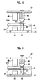
- the raw pipe 31 as a workpiece is disposed between the lower die 22 and the upper die 21 as shown in Fig. 13. Then, the end portion 31a of the raw pipe 31 is disposed over the lower mold 43 and the mandrel 42 is inserted into the end portion 31a of the raw pipe 31.
- the upper die 22 is brought down so as to clamp the end portion 31a of the raw pipe 31 between the upper mold 45 and the lower mold 43 as shown in Fig. 14. Simultaneously, the upper mold 45 and the lower mold 43 squeeze the end portion 31a to have a D-letter cross sectional shape.
- the mandrel 42 swings around the pivot 47 and presses the inner periphery of the end portion 31a of the raw pipe 31.
- the upper die 22 is further brought down with clamping the end portion 31a of the raw pipe 31 by means of repulsive force of the elastic body 49 so as to force down the upper clamp 46 onto the cylindrical portion 31b of the raw pipe 31 as shown in Fig. 15. Thereby the raw pipe 31 is bent and shaping of the branch tube 10 is completed.
- the branch tube 10 as the workpiece after shaping is detached therefrom.
- forming the broadened end portions of the branch tubes 10 and bending the branch tubes 10 are simultaneously carried out by the step S12 of Fig. 12. Therefore reduced number of steps for production of the branching tube 9 is realized.
- the flaring portion 7 may not be required to support the brazing metal.
- a minimum requirement is to keep certain clearances respectively between the multi-channel tube 1 and each of the branch tubes 10.
- the expanded end portion 6 of the multi-channel tube 1 may be expanded only in a direction perpendicular to the direction along the partition wall 3.
Landscapes
- Engineering & Computer Science (AREA)
- Mechanical Engineering (AREA)
- General Engineering & Computer Science (AREA)
- Chemical & Material Sciences (AREA)
- Combustion & Propulsion (AREA)
- Branch Pipes, Bends, And The Like (AREA)
Abstract
Description
- The present invention relates to a tube having a multi-channel tube and branch tubes branching therefrom, a connection structure therefor and a method for forming and connection thereof.
- Many machines are equipped with tubes for supply and/or circulation of fluid and, in certain cases, the tubes are required to branch into two or more branch tubes. Such a branching tube is formed in accordance with the following procedure. First, a multi-channel tube which has a partition wall to partition the interior thereof into plural channels is provided. Second, branch tubes are respectively inserted into the channels of the multi-channel tube. Finally, brazing among the multi-channel tube and the branch tubes are carried out.
- In this procedure, a gap between the branch tubes is in general too narrow to carry out brazing since the gap is regulated only by a thickness of the partition wall provided in the interior of the multi-channel tube. Therefore failure of brazing among the multi-channel tube and the branch tubes, in particular, between the partition wall and each of the branch tubes is likely to happen. Moreover, since the branch tubes having relatively narrow inner flow channels as compared with the multi-channel tube are inserted in the channels, steps are formed in the channels and cross sectional areas thereof are reduced. They may cause turbulent or not smooth flow of the fluid and increase flow resistance.
- The present invention has been achieved in view of the above problem.
- In accordance with a first aspect of the present invention, a tube is provided with: a multi-channel tube including a partition wall to partition an interior of the multi-channel tube into plural channels and an expanded end portion; branch tubes inserted into the expanded end portion and respectively communicating with the channels; and clearances for being filled with brazing metal, the clearances being respectively kept between the multi-channel tube and each of the branch tubes.
- Preferably, the branch tubes respectively include broadened end portions to be inserted into the expanded end portion of the multi-channel tube.
- Preferably, the expanded end portion of the multi-channel tube has greater diameters in any radial directions except a direction along the partition wall than a diameter of a main portion of the multi-channel tube.
- More preferably, the expanded end portion of the multi-channel tube is expanded only in a direction perpendicular to the direction along the partition wall.
- More preferably, the multi-channel tube includes a reducer portion having larger diameters at a first end linking with the expanded end portion and reducing diameters toward a second end linking with the main portion of the multi-channel tube.
- Still preferably, each of end portions of the branch tubes, the end portions being inserted into the expanded end portion of the multi-channel tube, is inclined with respect to a direction in which the end portion is inserted into the expanded end portion.
- Still preferably, the branch tubes are treated with presswork to have offsets with respect to the multi-channel tube.
- Still preferably, cylindrical portions of the respective branch tubes, the cylindrical portions being apart from end portions of the branch tubes, are separated from each other in a state where the branch tubes are inserted into the expanded end portion.
- Still preferably, the branch tubes have offsets with respect to the multi-channel tube in a state where the branch tubes are inserted into the expanded end portion, wherein first end portions of the branch tubes, the first end portions being inserted into the expanded end portion, are parallel with second end portions of the branch tubes, and wherein the branch tubes have different lengths.
- In accordance with a second aspect of the present invention, a method for connection of a multi-channel tube with plural branch tubes is provided with steps of: expanding an end portion of the multi-channel tube; inserting the branch tubes into the expanded end portion, respectively; and brazing each of the branch tubes with the expanded end portion.
- Preferably, the method is further provided with steps of:
- broadening an end portion of each branch tube; clamping a cylindrical portion of the branch tube, the cylindrical portion being apart from the broadened end portion of the branch tube; press-working the broadened end portion of the branch tube to have an offset with respect to the cylindrical portion of the branch tube; and forming the broadened end portion of the branch tube to have a D-letter cross sectional shape.
- More preferably, the step of broadening includes shaping the end portion of the branch tube to have an elliptic cross sectional shape.
- More preferably, the step of clamping includes steps of inserting a mandrel into the broadened end portion of the branch tube, and bringing down an upper die to clamp the cylindrical portion of the branch tube between an upper clamp and a lower clamp and fix the branch tube by means of repulsive force of an elastic body of the upper die, and wherein the steps of press-working and forming are simultaneously carried out by forcing down the upper die to press down an upper mold onto the broadened end portion of the branch tube and press down a mandrel presser onto the mandrel so that the broadened end portion of the branch tube is formed to have the D-letter cross sectional shape and the branch tube is bent.
- Still preferably, the method is further provided with steps of: clamping a cylindrical portion of each branch tube, the cylindrical portion being apart from an end portion of the branch tube; press-working the end portion of the branch tube to have an offset with respect to the cylindrical portion of the branch tube; and forming the end portion of the branch tube to have a D-letter cross sectional shape.
- Further preferably, the method is further provided with a step of: broadening an end portion of each branch tube before the steps of clamping, press-working and forming.
- Further preferably, the method is further provided with a step of: broadening an end portion of each branch tube to have an elliptic cross sectional shape before the steps of clamping, press-working and forming.
-
- Fig. 1 shows a vertical section of a connection structure among a multi-channel tube and branch tubes in accordance with a first embodiment of the present invention;
- Fig. 2 shows an enlargement taken from a circle II of Fig. 1;
- Fig. 3 shows a cross section of an expanded end portion of the multi-channel tube;
- Fig. 4 shows a vertical section of the expanded end portion of the multi-channel tube taken from the line IV-IV of Fig. 3;
- Fig. 5 shows a vertical section of the expanded end portion of the multi-channel tube taken from the line V-V of Fig. 3;
- Figs. 6A, 6B and 6C are respectively a plan view, a side view and a vertical sectional view of the branch tube, where Fig. 6C is taken from the line VIC-VIC of Fig. 6A;
- Fig. 7 is a flow chart of a method for forming the branch tube in accordance with the first embodiment of the present invention;
- Fig. 8 is a schematic drawing illustrating a step of setting the branch tube in a forming machine;
- Fig. 9 is a schematic drawing illustrating a step of clamping the branch tube;
- Fig. 10 is a schematic drawing illustrating a step of shaping an end portion of the branch tube and a step of bending;
- Fig. 11 shows a cross section taken from the line XI-XI of Fig. 10;
- Fig. 12 is a flow chart of a method for forming the branch tube in accordance with a second embodiment of the present invention;
- Fig. 13 is a schematic drawing illustrating a step of setting the branch tube in a forming machine;
- Fig. 14 is a schematic drawing illustrating a step of shaping an end portion of the branch tube;
- Fig. 15 is a schematic drawing illustrating a step of bending the branch tube;
- Fig. 16 shows a cross section taken from the line XVI-XVI of Fig. 15;
- Fig. 17 shows a cross section of the branch tube before and after shaping; and
- Fig. 18 shows a side view of an upper mold and a lower mold for shaping the end portion of the branch tube.
- Certain embodiments of the present invention will be described hereinafter with reference to the appended drawings.
- In accordance with a first embodiment of the present invention, a multi-channel tube 1 is brazed with two
branch tubes 10 to form abranching tube 9 as shown in Fig. 1. - The multi-channel tube 1 is provided with an outer
tubular portion 2 formed in a cylindrical shape and apartition wall 3, which partitions the interior of the multi-channel tube 1 into a pair ofchannels 4. Thechannels 4 are formed to be symmetrical and also have substantially the same cross sectional shape of a D-letter shape as shown in Figs. 3 through 5. The outertubular portion 2 is opened at both longitudinal ends. - One end portion of the multi-channel tube 1 is expanded in radial directions to have an expanded
end portion 6 and areducer portion 5 smoothly linking the expandedportion 6 with a main portion (un-expanded proximal portion) of the multi-channel tube 1. Thereducer portion 5 has a tapered shape becoming thinner from one end linking with the expandedportion 6 toward the other end linking with the main portion. More specifically, thereducer portion 5 gradually reduces diameters from a diameter of the expandedportion 6 to a diameter of the main portion so as to smoothly linking therewith. A tip end of the expandedportion 6 is further expanded to be aflaring portion 7, which is used for supporting brazing metal before and during brazing. - The
partition wall 3, except for a portion around an end thereof, is tightly fixed with inner peripheries of the outertubular portion 2 so as to keep air-tightness between both sides of thepartition wall 3. Theflaring portion 7 is separated from thepartition wall 3 at the end thereof so as to havespaces 8 therebetween to allow fused brazing metal to pass therethrough. - The
branch tubes 10 have substantially the same shape and the same dimension except for end portions thereof as shown in Figs. 6A through 6C. The end portion of eachbranch tube 10 has a D-letter broadenedportion 12 and atransitional portion 11. The D-letter broadenedportion 12 is composed of aflat portion 12a for being contact with thepartition wall 3 and anarc portion 12b for being contact with the outertubular portion 2 and hence has a D-letter cross sectional shape. Exterior dimensions of the D-letter broadenedportion 12 are greater than standard dimensions of eachchannel 4 and smaller than interior dimensions of the expandedportion 6. Each of the end portions of thebranch tubes 10, which is inserted into the expandedend portion 6 of the multi-channel tube 1, is inclined with respect to an insertion direction in which the end portion is inserted into the expandedend portion 6. - The
flat portion 12a stepwise bulges outward from a straight portion of thebranch tube 10 so as to form astep portion 13 where a boundary between the D-letter broadenedportion 12 and thetransitional portion 11 substantially exists as shown in Fig. 6C. Thestep portion 13 is to recede from anend surface 3a of thepartition wall 3 in a length d in a state that thebranch tube 10 is inserted into the multi-channel tube 1 as shown in Fig. 2. - A method for forming the
branch tube 10 will be described hereinafter with reference to Figs. 7 through 11. The method for forming utilizes alower die 21 and anupper die 22 as shown in Figs. 8 through 11. On thelower die 21, asupport member 23, amandrel 24, alower mold 25 and alower clamp 26 are provided. Beneath theupper die 22, amandrel presser 27, anupper mold 28 and anupper clamp 29 are provided. - The
support member 23 is vertically movably attached to thelower die 21 with aspring 30 intervening therebetween. Themandrel presser 27 is so dimensioned as to press down thesupport member 23 when theupper die 22 goes down. Themandrel 24 has a D-letter cross section which is smaller than the cross section of the interior of the end portion of thebranch tube 10 and projects sideward from thesupport member 23 to be inserted into anend portion 31a of araw pipe 31. Theraw pipe 31 is a raw material to form thebranch tube 10. Theend portion 31a of theraw pipe 31 is expanded in advance and another portion thereof, which is apart from theend portion 31a to a certain extent, is acylindrical portion 31b left cylindrical as is produced. - As shown in Fig. 11, the
lower mold 25 has a flat upper surface to shape a lower side of theend portion 31a of theraw pipe 31 into a flat portion by presswork. A lower side of theupper mold 28 has a halfcylindrical recess portion 32 to shape an upper side of theend portion 31a of the raw pipe into a complementary shape. - The
upper clamp 29 is attached to theupper die 22 with anelastic body 33 of, for example, urethane rubber intervening therebetween and is vertically movable with respect to theupper die 22. Theupper clamp 29 and thelower clamp 26 in combination are configured to support thecylindrical portion 31b of theraw pipe 31. - Steps of the method can be illustrated as the flowchart of Fig. 7. First, as a step S1 of Fig. 7, the
raw pipe 31 for forming thebranch tube 10 as a workpiece is disposed between thelower die 22 and theupper die 21 as shown in Fig. 8. Then, thecylindrical portion 31b of theraw pipe 31 is disposed on thelower clamp 26 and themandrel 24 is inserted into theend portion 31a of theraw pipe 31. Next, as a step S2, theupper die 22 is brought down so as to clamp the cylindrical 31b of thepipe 31 between theupper clamp 29 and thelower clamp 26 and fix theraw pipe 31 by means of repulsive force of theelastic body 33 of theupper die 22 as shown in Fig. 9. - As a step S3, the
upper die 22 is further brought down so as to force down theupper mold 28 onto theend portion 31a of theraw pipe 31 and press down themandrel presser 27 onto themandrel 24 as shown in Fig. 10. Thereby, theend portion 31a of theraw pipe 31 is formed to have a D-letter cross sectional shape and therawpipe 31 is bent. Meanwhile, since, as is already described, themandrel 24 has the D-letter cross section smaller than the end portion of thebranch tube 10, in the course of pressing thebranch tube 10 from both sides by thelower mold 25 and theupper mold 28, themandrel 24 supports thebranch tube 10 from the interior thereof so that the end portion of thebranch tube 10 is formed to have the D-letter cross section. - After shaping the
branch tube 10, as a step S4, thebranch tube 10 as the workpiece after shaping is detached therefrom. - Next, steps of connection of the multi-channel tube 1 with the
branch tubes 10 will be described hereinafter. Thebranch tubes 10 are respectively inserted into thechannels 4 through theend portion 6 of the multi-channel tube 1 so that tip ends of thebranch tubes 10 abut on and are stopped by an inner periphery of thereducer portion 5. Next, brazingmetal 14 is disposed on the end surfaces of the multi-channel tube 1 and around peripheries of thebranch tubes 10 as indicated by a double-dotted line in Fig. 2. Thebrazing metal 14 is also disposed on theend surface 3a of thepartition wall 3 with facility since thebranch tubes 2 are separated from each other. Thebranch tubes 10 may not necessarily abut on the inner periphery of thereducer portion 5 despite the above description. - Next, the multi-channel tube 1 in combination with the
branch tubes 10 is inserted in any heating chamber in a state that the multi-channel tube 1 is oriented downward and thebranch tubes 10 are oriented upward. Then they are heated. By heating, thebrazing metal 14 is fused and flows downward by gravity force. The flowingbrazing metal 14 flows into clearances respectively kept between the multi-channel tube 1 and each of thebranch tubes 10. When they are cooled, the fusedbrazing metal 14 solidifies to form afillet 15. In this occasion, string-like brazing metal 14 may be adhered to and along the outer periphery of thebranch tube 10 so as to be a D-letter shape and fused by heating by means of a burner so that fusedbrazing metal 14 flows into where is between the inner periphery of the multi-channel tube 1 and the outer periphery of eachbranch tube 10. Thereby therespective branch tubes 10 are brazed with the multi-channel tube 1 with sufficient unitization ranging total circumferences thereof. - In accordance with the present first embodiment, fusion and flow of the
brazing metal 14 take place constantly at positions receding from the ends of the multi-channel tube 1. Therefore the fusedbrazing metal 14 is promoted to flow into clearances kept between the multi-channel tube 1 and each of thebranch tubes 10 and further prevented from spilling outward. - Since the end portions of the
branch tubes 10 are inclined with respect to the insertion directions thereof, the end portions generate smaller resistance to the flow of the fluid therein as compared with a case where the end portions are perpendicular to the insertion directions. - The
branch tubes 10 have offsets with respect to the multi-channel tube 1 and the cylindrical portions of thebranch tubes 10 are separated from each other in a state where the branch tubes are inserted into the expanded end portion. Such a structure provides easiness and therefore reliability in placing thebrazing metal 14 around the total circumferences of thebranch tubes 10 and connection of the multi-channel tube 1 with thebranch tubes 10. - Since the outer periphery of the end portion of the outer
tubular portion 2 is provided with the flaringportion 7 for supporting thebrazing metal 14, relatively large clearances between the inner periphery of the outertubular portion 2 and the outer peripheries of thebranch tubes 10 are kept. The relatively large clearances promote the fusedbrazing metal 14 to flow therein and keep the brazingmetal 14 therein, thereby thefillet 15 is uniformly formed to range the total circumferences of thebranch tubes 10. - Since the
reducer portion 5 receives the insertedbranch tubes 10, nothing but pushing thebranch tubes 10 to abut on thereducer portion 5 is required to position thebranch tubes 10 to predetermined positions. It leads to easiness and reliability in working of production of the branchingtube 9. - The
reducer portion 5 and the expandedend portion 6 having the same diameter as thereducer portion 5 in combination hold thebranch tubes 10 in the regular positions and hence provide stability in positioning thebranch tubes 10. It leads to further easiness and reliability in working of production of the branchingtube 9. - Since the
spaces 8 held between the flaringportion 7 and thepartition wall 3 at the end thereof allow the fusedbrazing metal 14 to pass therethrough, the fusedbrazing metal 14 around one of thebranch tubes 10 may easily flow toward another of thebranch tubes 10 via thespaces 8. Therefore the unitization ranging total circumferences of thebranch tubes 10 is further assured and hence reliability of the connection is further assured. - Forming the broadened end portions of the
branch tubes 10 and bending thebranch tubes 10 are simultaneously carried out by the step S3 of Fig. 7, namely forcing down theupper die 22 to press down anupper mold 28 onto the broadened end portions of thebranch tubes 10 and press down amandrel presser 27 onto themandrel 24. Therefore reduced number of steps for production of the branchingtube 9 is realized. - Formation of the D-letter cross section of the broadened end portion of the
branch tube 10 is carried out in a state that themandrel 24 having the D-letter cross section is inserted in theend portion 31a of theraw pipe 31, any irregular and localized deformation can be prevented. It leads to precise production. - Since the
branch tubes 10 are inserted in the broadened end portion of the multi-channel tube 1, thicknesses of the outer walls of thebranch tubes 10 do not severely reduce the cross sectional area of the flow paths in the branchingtube 9. Therefore smooth flow of the fluid therein can be assured. It also leads to a smaller resistance to the flow of the fluid therein. Smooth flow of the fluid can be realized. - A second embodiment of the present invention will be described hereinafter with reference to Figs. 12 through 18.
- As compared with the above first embodiment, the second embodiment differs only in a method of shaping the
branch tubes 10 and is substantially the same as the first embodiment in the other respects. - In accordance with the present second embodiment, on the
lower die 21, asupport member 41, amandrel 42, alower mold 43 and alower clamp 44 are provided, and, on theupper die 22, anupper mold 45 and anupper clamp 46 are provided. - The
support member 41 is fixed on thelower die 21. Themandrel 42 has a D-letter cross section which is smaller than the cross section of the interior of the end portion of thebranch tube 10. Apivot 47 of thesupport member 41 swingably supports themandrel 42. - As shown in Fig. 18, the
lower mold 43 has a halfcylindrical recess portion 48 to shape a lower side of theend portion 31a of the raw pipe into a complementary shape. Theupper mold 45 has a flat lower surface to shape a lower side of theend portion 31a of theraw pipe 31 into a flat portion by presswork. - The
upper clamp 46 is attached to theupper die 22 with anelastic body 49 of, for example, urethane rubber interveneing therebetween and is vertically movable with respect to theupper die 22. The upper clamp46 and thelower clamp 44 in combination are configured to support thecylindrical portion 31b of theraw pipe 31. - In accordance with the present second embodiment, as a step S11 of Fig. 12, the
raw pipe 31 as a workpiece is disposed between thelower die 22 and theupper die 21 as shown in Fig. 13. Then, theend portion 31a of theraw pipe 31 is disposed over thelower mold 43 and themandrel 42 is inserted into theend portion 31a of theraw pipe 31. Next, as a step S12, theupper die 22 is brought down so as to clamp theend portion 31a of theraw pipe 31 between theupper mold 45 and thelower mold 43 as shown in Fig. 14. Simultaneously, theupper mold 45 and thelower mold 43 squeeze theend portion 31a to have a D-letter cross sectional shape. Then, themandrel 42 swings around thepivot 47 and presses the inner periphery of theend portion 31a of theraw pipe 31. Next, as a step S13, theupper die 22 is further brought down with clamping theend portion 31a of theraw pipe 31 by means of repulsive force of theelastic body 49 so as to force down theupper clamp 46 onto thecylindrical portion 31b of theraw pipe 31 as shown in Fig. 15. Thereby theraw pipe 31 is bent and shaping of thebranch tube 10 is completed. After shaping thebranch tube 10, as a step S14, thebranch tube 10 as the workpiece after shaping is detached therefrom. - In accordance with the present second embodiment, forming the broadened end portions of the
branch tubes 10 and bending thebranch tubes 10 are simultaneously carried out by the step S12 of Fig. 12. Therefore reduced number of steps for production of the branchingtube 9 is realized. - The above embodiments may be modified. For example, though broadening and shaping of the
end portion 31a into the D-letter cross sectional shape are simultaneously carried out in the above description, shaping theend portion 31a to have an elliptic cross sectional shape may be carried out before the steps of clamping, press-working and forming. It may leads to better shaping of theend portion 31a into the D-letter cross sectional shape. - Moreover, the flaring
portion 7 may not be required to support the brazing metal. A minimum requirement is to keep certain clearances respectively between the multi-channel tube 1 and each of thebranch tubes 10. Further, though theend portion 6 of the multi-channel tube 1 is expanded to have greater diameters in any radial directions except a direction along thepartition wall 3 than a diameter of a main portion of the multi-channel tube 1 in accordance with the above description, the expandedend portion 6 of the multi-channel tube 1 may be expanded only in a direction perpendicular to the direction along thepartition wall 3. - Although the invention has been described above by reference to certain embodiments of the invention, the invention is not limited to the embodiments described above. Modifications and variations of the embodiments described above will occur to those skilled in the art, in light of the above teachings.
Claims (16)
- A tube (9) comprising:a multi-channel tube (1) including a partition wall (3) to partition an interior of the multi-channel tube (1) into plural channels (4) and an expanded end portion (6);branch tubes (10) inserted into the expanded end portion (6) and respectively communicating with the channels (4); andclearances (15) for being filled with brazing metal, the clearances (15) being respectively kept between the multi-channel tube (1) and each of the branch tubes (10) .
- The tube (9) of claim 1, wherein the branch tubes (10) respectively include broadened endportions to be inserted into the expanded end portion (6) of the multi-channel tube (1).
- The tube (9) of claim 1, wherein the expanded end portion (6) of the multi-channel tube (1) has greater diameters in any radial directions except a direction along the partition wall (3) than a diameter of a main portion of the multi-channel tube (1).
- The tube (9) of claim 3, wherein the expanded end portion (6) of the multi-channel tube (1) is expanded only in a direction perpendicular to the direction along the partition wall (3).
- The tube (9) of claim 3, wherein the multi-channel tube (1) includes a reducer portion (5) having larger diameters at a first end linking with the expanded end portion (6) and reducing diameters toward a second end linking with the main portion of the multi-channel tube (1).
- The tube (9) of claim 1, wherein each of end portions of the branch tubes (10), the end portions being inserted into the expanded end portion (6) of the multi-channel tube (1), is inclined with respect to a direction in which the end portion is inserted into the expanded end portion (6).
- The tube (9) of claim 1, wherein the branch tubes (10) are treated with presswork to have offsets with respect to the multi-channel tube (1).
- The tube (9) of claim 1, wherein cylindrical portions of the respective branch tubes (10), the cylindrical portions being apart from end portions of the branch tubes (10), are separated from each other in a state where the branch tubes (10) are inserted into the expanded end portion (6).
- The tube (9) of claim 1, wherein the branch tubes (10) have offsets with respect to the multi-channel tube (1) in a state where the branch tubes (10) are inserted into the expanded end portion (6), wherein first end portions of the branch tubes (10), the first end portions being inserted into the expanded end portion (6), are parallel with second end portions of the branch tubes (10), and wherein the branch tubes (10) have different lengths.
- A method for connection of a multi-channel tube (1) with plural branch tubes (10), the method comprising steps of:expanding an end portion (6) of the multi-channel tube (1);inserting the branch tubes (10) into the expanded end portion (6), respectively; andbrazing each of the branch tubes (10) with the expanded end portion (6).
- The method of claim 10, further comprising steps of:broadening an end portion of each branch tube (10);clamping a cylindrical portion of the branch tube (10), the cylindrical portion being apart from the broadened end portion of the branch tube (10);press-working the broadened end portion of the branch tube (10) to have an offset with respect to the cylindrical portion of the branch tube (10); andforming the broadened end portion of the branch tube (10) to have a D-letter cross sectional shape.
- The method of claim 11, wherein the step of broadening includes shaping the end portion of the branch tube (10) to have an elliptic cross sectional shape.
- The method of claim 11, wherein the step of clamping includes steps of inserting a mandrel (24) into the broadened end portion of the branch tube (10), and bringing down an upper die (22) to clamp the cylindrical portion of the branch tube (10) between an upper clamp (29) and a lower clamp (26) and fix the branch tube (10) by means of repulsive force of an elastic body (33) of the upper die (22), and wherein the steps of press-working and forming are simultaneously carried out by forcing down the upper die (22) to press down an upper mold (28) onto the broadened end portion of the branch tube (10) and press down a mandrel presser (27) onto the mandrel (24) so that the broadened end portion of the branch tube (10) is formed to have the D-letter cross sectional shape and the branch tube (10) is bent.
- The method of claim 10, further comprising steps of:clamping a cylindrical portion of each branch tube (10), the cylindrical portion being apart from an end portion of the branch tube (10);press-working the end portion of the branch tube (10) to have an offset with respect to the cylindrical portion of the branch tube (10); andforming the end portion of the branch tube (10) to have a D-letter cross sectional shape.
- The method of claim 14, further comprising a step of:broadening an end portion of each branch tube (10) before the steps of clamping, press-working and forming.
- The method of claim 14, further comprising a step of:broadening an end portion of each branch tube (10) to have an elliptic cross sectional shape before the steps of clamping, press-working and forming.
Applications Claiming Priority (3)
| Application Number | Priority Date | Filing Date | Title |
|---|---|---|---|
| JP2005158197A JP2006329411A (en) | 2005-05-30 | 2005-05-30 | Piping connecting structure comprising multi-drilled pipe and a plurality of branch pipes, and branch pipe forming method |
| JP2005158200A JP4778728B2 (en) | 2005-05-30 | 2005-05-30 | Branch pipe forming method |
| JP2005158198A JP4713947B2 (en) | 2005-05-30 | 2005-05-30 | Piping composed of a multi-hole pipe and a plurality of branch pipes, a connection structure thereof, and a method of forming the branch pipe |
Publications (2)
| Publication Number | Publication Date |
|---|---|
| EP1728985A1 true EP1728985A1 (en) | 2006-12-06 |
| EP1728985B1 EP1728985B1 (en) | 2008-12-17 |
Family
ID=36716572
Family Applications (1)
| Application Number | Title | Priority Date | Filing Date |
|---|---|---|---|
| EP06011021A Expired - Fee Related EP1728985B1 (en) | 2005-05-30 | 2006-05-29 | Connection structure of multi-channel tube with branching tube and connection method therefor |
Country Status (3)
| Country | Link |
|---|---|
| US (1) | US20060279082A1 (en) |
| EP (1) | EP1728985B1 (en) |
| DE (1) | DE602006004253D1 (en) |
Cited By (2)
| Publication number | Priority date | Publication date | Assignee | Title |
|---|---|---|---|---|
| CN102650361A (en) * | 2012-05-18 | 2012-08-29 | 中国水电顾问集团西北勘测设计研究院 | Flat-bottom equal-section steel bifurcated pipe |
| CN107614149A (en) * | 2015-11-03 | 2018-01-19 | 田二范 | Manufacture method that flexible pipe connection has with branched pipe and bifurcation connector and the fuel supply flexible pipe manufactured using it |
Citations (3)
| Publication number | Priority date | Publication date | Assignee | Title |
|---|---|---|---|---|
| US4796426A (en) * | 1982-07-06 | 1989-01-10 | Feuling James J | High efficiency transition element positioned intermediate multi-cylinder exhaust system and secondary pipe assemblies |
| EP1547715A1 (en) * | 2003-12-26 | 2005-06-29 | Calsonic Kansei Corporation | Connection structure of multi-channel tube with branching tube and connection method therefor |
| EP1657482A2 (en) * | 2004-11-10 | 2006-05-17 | Calsonic Kansei Corporation | Pipe arrangement branching structure, method for working perforated pipe and method for working branch pipe |
Family Cites Families (5)
| Publication number | Priority date | Publication date | Assignee | Title |
|---|---|---|---|---|
| US1984242A (en) * | 1932-06-25 | 1934-12-11 | Babcock & Wilcox Co | Conduit junction |
| DE9102151U1 (en) * | 1990-03-06 | 1991-05-16 | Geberit Ag, Jona, St.Gallen, Ch | |
| US5372388A (en) * | 1993-04-30 | 1994-12-13 | American Pipe & Plastics, Inc. | Integral multi-duct conduit section |
| JP2856705B2 (en) * | 1996-05-08 | 1999-02-10 | 株式会社三五 | Confluence pipe and its manufacturing method |
| US20040089439A1 (en) * | 2002-11-07 | 2004-05-13 | Treverton Andrew Clare | Tube-to-tube heat exchanger assembly |
-
2006
- 2006-05-26 US US11/441,398 patent/US20060279082A1/en not_active Abandoned
- 2006-05-29 DE DE602006004253T patent/DE602006004253D1/en not_active Expired - Fee Related
- 2006-05-29 EP EP06011021A patent/EP1728985B1/en not_active Expired - Fee Related
Patent Citations (3)
| Publication number | Priority date | Publication date | Assignee | Title |
|---|---|---|---|---|
| US4796426A (en) * | 1982-07-06 | 1989-01-10 | Feuling James J | High efficiency transition element positioned intermediate multi-cylinder exhaust system and secondary pipe assemblies |
| EP1547715A1 (en) * | 2003-12-26 | 2005-06-29 | Calsonic Kansei Corporation | Connection structure of multi-channel tube with branching tube and connection method therefor |
| EP1657482A2 (en) * | 2004-11-10 | 2006-05-17 | Calsonic Kansei Corporation | Pipe arrangement branching structure, method for working perforated pipe and method for working branch pipe |
Cited By (3)
| Publication number | Priority date | Publication date | Assignee | Title |
|---|---|---|---|---|
| CN102650361A (en) * | 2012-05-18 | 2012-08-29 | 中国水电顾问集团西北勘测设计研究院 | Flat-bottom equal-section steel bifurcated pipe |
| CN107614149A (en) * | 2015-11-03 | 2018-01-19 | 田二范 | Manufacture method that flexible pipe connection has with branched pipe and bifurcation connector and the fuel supply flexible pipe manufactured using it |
| CN107614149B (en) * | 2015-11-03 | 2019-06-18 | 田二范 | The manufacturing method of hose connection branched pipe and bifurcation connector tool and fuel manufacture using it are for applying hose |
Also Published As
| Publication number | Publication date |
|---|---|
| DE602006004253D1 (en) | 2009-01-29 |
| US20060279082A1 (en) | 2006-12-14 |
| EP1728985B1 (en) | 2008-12-17 |
Similar Documents
| Publication | Publication Date | Title |
|---|---|---|
| US4799540A (en) | Heat exchanger | |
| US6056047A (en) | Manifold for heat exchanger and baffles therefor | |
| US7069760B2 (en) | Device and method for manufacturing a curved metal tube or rod | |
| BR112019018762B1 (en) | PRESS MOLD AND METHOD FOR MAKING STEEL TUBE | |
| CN1322299C (en) | Method for producing head element for heater, and head element using this method | |
| EP1728985B1 (en) | Connection structure of multi-channel tube with branching tube and connection method therefor | |
| CA2287343C (en) | Manifold incorporating baffles and method of manufacturing same | |
| JP5038819B2 (en) | Bending method for flared tube | |
| JP2008510625A (en) | Method and apparatus for producing a hollow profile seam welded longitudinally | |
| JP4323181B2 (en) | Double pipe joint and method for manufacturing the same | |
| JP2007010199A (en) | Multiple-way pipe and method of manufacturing the same | |
| JP3703998B2 (en) | Pipe welded structure | |
| JP2002239639A (en) | Method and device for bending pipe | |
| JP5156817B2 (en) | Piping consisting of multi-hole pipes and multiple branch pipes and their connection structure | |
| JP4713947B2 (en) | Piping composed of a multi-hole pipe and a plurality of branch pipes, a connection structure thereof, and a method of forming the branch pipe | |
| JP7137829B2 (en) | ROUND STEEL PIPE MANUFACTURING METHOD, ROUND STEEL PIPE MANUFACTURER | |
| US3055097A (en) | Method of making a reinforced brazed tubular joint | |
| CN218050058U (en) | Heat exchange tube flaring and fluid expanded joint integrated device with mandrel auxiliary clamping function | |
| JP4258003B2 (en) | Heat exchanger tank | |
| KR100352788B1 (en) | Method for hydroforming flange-shaped tube using plate | |
| JP2009052634A (en) | Brazed joint | |
| JP4778728B2 (en) | Branch pipe forming method | |
| AU2003286429A1 (en) | Finned tube for heat exchangers, heat exchanger, apparatus for fabricating heat exchanger finned tube and process for fabricating heat exchanger finned tube | |
| JP4580733B2 (en) | Perforated tube processing method | |
| JP2006308028A (en) | Double pipe and its manufacturing method |
Legal Events
| Date | Code | Title | Description |
|---|---|---|---|
| PUAI | Public reference made under article 153(3) epc to a published international application that has entered the european phase |
Free format text: ORIGINAL CODE: 0009012 |
|
| AK | Designated contracting states |
Kind code of ref document: A1 Designated state(s): AT BE BG CH CY CZ DE DK EE ES FI FR GB GR HU IE IS IT LI LT LU LV MC NL PL PT RO SE SI SK TR |
|
| AX | Request for extension of the european patent |
Extension state: AL BA HR MK YU |
|
| 17P | Request for examination filed |
Effective date: 20061211 |
|
| 17Q | First examination report despatched |
Effective date: 20070124 |
|
| AKX | Designation fees paid |
Designated state(s): DE FR GB |
|
| GRAP | Despatch of communication of intention to grant a patent |
Free format text: ORIGINAL CODE: EPIDOSNIGR1 |
|
| GRAS | Grant fee paid |
Free format text: ORIGINAL CODE: EPIDOSNIGR3 |
|
| GRAA | (expected) grant |
Free format text: ORIGINAL CODE: 0009210 |
|
| AK | Designated contracting states |
Kind code of ref document: B1 Designated state(s): DE FR GB |
|
| REG | Reference to a national code |
Ref country code: GB Ref legal event code: FG4D |
|
| REF | Corresponds to: |
Ref document number: 602006004253 Country of ref document: DE Date of ref document: 20090129 Kind code of ref document: P |
|
| PLBE | No opposition filed within time limit |
Free format text: ORIGINAL CODE: 0009261 |
|
| STAA | Information on the status of an ep patent application or granted ep patent |
Free format text: STATUS: NO OPPOSITION FILED WITHIN TIME LIMIT |
|
| 26N | No opposition filed |
Effective date: 20090918 |
|
| REG | Reference to a national code |
Ref country code: FR Ref legal event code: ST Effective date: 20100129 |
|
| PG25 | Lapsed in a contracting state [announced via postgrant information from national office to epo] |
Ref country code: FR Free format text: LAPSE BECAUSE OF NON-PAYMENT OF DUE FEES Effective date: 20090602 |
|
| PG25 | Lapsed in a contracting state [announced via postgrant information from national office to epo] |
Ref country code: DE Free format text: LAPSE BECAUSE OF NON-PAYMENT OF DUE FEES Effective date: 20091201 |
|
| GBPC | Gb: european patent ceased through non-payment of renewal fee |
Effective date: 20100529 |
|
| PG25 | Lapsed in a contracting state [announced via postgrant information from national office to epo] |
Ref country code: GB Free format text: LAPSE BECAUSE OF NON-PAYMENT OF DUE FEES Effective date: 20100529 |