EP1728905A2 - Driving device for terry motion members in cloth-shifting-type pile loom - Google Patents
Driving device for terry motion members in cloth-shifting-type pile loom Download PDFInfo
- Publication number
- EP1728905A2 EP1728905A2 EP06009841A EP06009841A EP1728905A2 EP 1728905 A2 EP1728905 A2 EP 1728905A2 EP 06009841 A EP06009841 A EP 06009841A EP 06009841 A EP06009841 A EP 06009841A EP 1728905 A2 EP1728905 A2 EP 1728905A2
- Authority
- EP
- European Patent Office
- Prior art keywords
- linking
- drive
- rocking
- driving
- terry motion
- Prior art date
- Legal status (The legal status is an assumption and is not a legal conclusion. Google has not performed a legal analysis and makes no representation as to the accuracy of the status listed.)
- Withdrawn
Links
- 230000007246 mechanism Effects 0.000 claims abstract description 36
- 238000000034 method Methods 0.000 claims abstract description 15
- 230000008569 process Effects 0.000 claims abstract description 14
- 230000008859 change Effects 0.000 claims description 11
- 238000010009 beating Methods 0.000 description 34
- 239000004744 fabric Substances 0.000 description 31
- 230000004044 response Effects 0.000 description 12
- 238000009941 weaving Methods 0.000 description 12
- 238000010586 diagram Methods 0.000 description 6
- 235000014676 Phragmites communis Nutrition 0.000 description 3
- 230000008901 benefit Effects 0.000 description 2
- 230000001771 impaired effect Effects 0.000 description 2
- 238000003780 insertion Methods 0.000 description 2
- 230000037431 insertion Effects 0.000 description 2
- 238000005299 abrasion Methods 0.000 description 1
- 230000004048 modification Effects 0.000 description 1
- 238000012986 modification Methods 0.000 description 1
- 230000002093 peripheral effect Effects 0.000 description 1
- 239000011435 rock Substances 0.000 description 1
Images





Classifications
-
- D—TEXTILES; PAPER
- D03—WEAVING
- D03D—WOVEN FABRICS; METHODS OF WEAVING; LOOMS
- D03D39/00—Pile-fabric looms
- D03D39/22—Terry looms
- D03D39/223—Cloth control
Definitions
- the present invention relates to driving devices for terry motion members in cloth-shifting-type pile looms.
- the present invention relates to a driving device for let-off-side and take-up-side terry motion members included in a cloth-shifting-type pile loom, the driving device including drive-transmission mechanisms provided respectively for the two terry motion members and both linked to a driving shaft of common driving means provided for the two terry motion members.
- the drive-transmission mechanisms include a rocking member rocked by the driving means, supporting units respectively supporting the terry motion members, and linking means including at least one linking member that links the rocking member to the supporting units.
- Patent Document 1 discloses an example of such a cloth-shifting-type pile loom.
- a ground-warp tension roller serving as a let-off-side terry motion member and a cloth guide roller serving as a take-up-side terry motion member are respectively supported by supporting levers (rocking levers) serving as supporting units.
- the supporting levers provided respectively for the two terry motion members are linked to a common rocking lever via corresponding linking rods.
- the rocking lever is rocked by driving means that includes a driving motor and a crank unit. When the rocking lever is rocked by the driving means, the supporting levers are rocked accordingly, thereby moving the let-off-side and take-up-side terry motion members.
- the let-off-side and take-up-side terry motion members are mechanically linked to each other.
- the two terry motion members move while maintaining a fixed distance therebetween.
- a relationship between driving modes (driving amounts, drive timings, driving patterns, etc.) of the two terry motion members is always constant in a weaving operation.
- a warp tension fluctuates in response to a shedding motion in each weaving cycle.
- the pile loom according to Patent Document 1 cannot actively compensate for the fluctuation of warp tension in each weaving cycle.
- the beating property for each inserted weft thread may be impaired due to an insufficient warp tension for a beating operation, or the warp threads may break if the warp tension at the time of a shedding motion reaches an excess value.
- Patent Document 2 Japanese Unexamined Patent Application Publication No. 11-172552 (Patent Document 2) and Japanese Unexamined Patent Application Publication No. 2-47334 (Patent Document 3) discuss other examples of a cloth-shifting-type pile loom.
- the let-off-side and take-up-side terry motion members are driven by a terry motion mechanism, which includes driving means having cam units respectively provided for the let-off-side and take-up-side terry motion members and drive-transmission mechanisms including, for example, rocking levers that are rocked by the corresponding cam units.
- the cam units are replaceable with motors, such as servomotors.
- the let-off-side and take-up-side terry motion members are not mechanically linked to each other, but are driven individually with designated driving motors (servomotors).
- the driving modes of the let-off-side and take-up-side terry motion members can be changed individually to desired modes. Therefore, the let-off-side terry motion member can be driven in a movement pattern that compensates for the fluctuation of warp tension in the shifting process of the let-off-side terry motion member. Accordingly, this solves the problems existed in the pile loom of Patent Document 1.
- the let-off-side terry motion member receives a force corresponding to the warp tension
- the take-up-side terry motion member receives a force corresponding to the tension of a woven cloth.
- the drive-transmission mechanisms corresponding to the let-off-side and take-up-side terry motion members are mechanically linked to each other as in the pile loom of Patent Document 1, the forces applied to the terry motion members are balanced out.
- the magnitude of load applied to the driving means due to the tension mentioned above is small.
- a large magnitude of load applied to the driving means may lead to, for example, an increase in power consumption or damaging of the driving means at an early stage of use.
- the driving means includes the cam units as set forth in Patent Document 2, the rotary shafts of cams and the rocking shafts of the rocking levers, for example, may be subject to a large magnitude of load. This may lead to an abrasion or damaging of these shafts at an early stage of use.
- the present invention provides a driving device for let-off-side and take-up-side terry motion members included in a cloth-shifting-type pile loom, the driving device including drive-transmission mechanisms provided respectively for the two terry motion members and both linked to a driving shaft of common driving means provided for the two terry motion members.
- the drive-transmission mechanisms include a rocking member rocked by the driving means, supporting units respectively supporting the terry motion members, and linking means including at least one linking member that links the rocking member to the supporting units.
- the driving device is characterized in that one of the drive-transmission mechanisms corresponding to the let-off-side or take-up-side terry motion member is additionally provided with drive-changing means having a designated actuator as a driving source and changing a rocking position of one of the supporting units included in the one of the drive-transmission mechanisms with respect to a certain rotary phase of the driving shaft.
- the drive-changing means is actuated in a shifting process of the let-off-side or take-up-side terry motion member.
- the drive-changing means may include a driven member connected to the linking means and driven by the actuator so as to move the at least one linking member included in the linking means, the movement of the one linking member changing a distance between a connection part for connecting the rocking member and the linking means and a connection part for connecting the one of the supporting units and the linking means.
- the at least one linking member of the linking means may include a first linking member and a second linking member.
- the driven member included in the drive-changing means may be connected to a connection part between the first linking member and the second linking member and may be driven by the actuator so as to change an angle formed between the first linking member and the second linking member.
- the one of the drive-transmission mechanisms may be capable of changing a connecting position of a connection part between the one of the supporting units and the linking means with respect to the one of the supporting units or a connecting position of a connection part between the rocking member and the linking means with respect to the rocking member.
- the drive-changing means may include a driven member that is connected to the at least one linking member of the linking means whose connecting position with respect to the one of the supporting units or the rocking member is changeable, the driven member being driven by the actuator so as to change the connecting position.
- the let-off-side and take-up-side terry motion members are driven by common driving means, and are linked to the driving shaft of the common driving means via the respective drive-transmission mechanisms.
- one of the drive-transmission mechanisms corresponding to the let-off-side or take-up-side terry motion member is additionally provided with the drive-changing means, which has the designated actuator as a driving source and changes a rocking position of one of the supporting units with respect to a predetermined rotary phase of the driving shaft.
- the drive-changing means since the drive-changing means is actuated in a shifting process of the terry motion member, the driving mode of the terry motion member corresponding to the one of drive-transmission mechanisms driven based on the driving means is subject to a change by the drive-changing means.
- the driving modes of the two terry motion members are not limited to the driving mode based on the driving means. Instead, the driving mode for one of the terry motion members may be set to a desired mode independently of the driving mode for the other terry motion member. Accordingly, this effectively prevents the beating property from being impaired or the warp threads from breaking.
- FIGs. 1 to 4 illustrate a first embodiment according to the present invention.
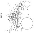
- Figs. 1 and 2 show a cloth-shifting-type pile loom to which the present invention is applied.
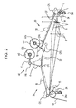
- Fig. 2 is a schematic diagram showing a relevant portion of the present invention.
- pile warp threads PT shown in Fig. 1 are not illustrated.
- a cloth-shifting-type pile loom 1 includes an upper pile-warp beam 2 around which a plurality of pile warp threads PT are wound in a sheet-like manner, and a lower ground-warp beam 3 around which a plurality of ground warp threads GT are wound in a sheet-like manner.
- the pile warp threads PT are fed from the pile-warp beam 2 and are wound around two guide rollers 6, 6 and a pile-warp tension roller 7 disposed downstream of the guide rollers 6, 6 so as to be supplied to a cloth fell CF of a woven cloth W via a heald 8 and a reed 5.
- the ground warp threads GT are fed from the ground-warp beam 3 and are wound around a ground-warp tension roller 15, which defines a let-off-side terry motion member. Similar to the pile warp threads PT, the ground warp threads GT guided by the tension roller 15 are then supplied to the cloth fell CF via the heald 8 and the reed 5.
- the pile warp threads PT and the ground warp threads GT form the woven cloth W.
- the woven cloth W is subsequently guided by a cloth guide roller 16, which defines a take-up-side terry motion member, towards a take-up roller 11 and guide rollers 12, 13 so as to be finally taken up by a cloth roller 14.
- the ground-warp tension roller 15 i.e. the let-off-side terry motion member
- the cloth guide roller 16 i.e. the take-up-side terry motion member
- a common designated driving motor m1 that is independent of a driving source for the pile loom 1.
- Each of the terry motion members is provided with a drive-transmission mechanism which connects the terry motion member to the driving motor m1.
- the driving motor m1 is fixed to a base frame of the pile loom 1, and has an output shaft m1s (driving shaft) to which a rocking lever 18 serving as a rocking member is attached.
- the rocking lever 18 is used in common between a drive-transmission mechanism 20 corresponding to the ground-warp tension roller 15 and a drive-transmission mechanism 30 corresponding to the cloth guide roller 16.
- the drive-transmission mechanism 20 includes the rocking lever 18, a pair of supporting levers 24 serving as a supporting unit for supporting the ground-warp tension roller 15, and linking means defined by linking rods 22, 26 that link the rocking lever 18 and the supporting levers 24.
- the supporting levers 24 are provided with a rocking shaft 24a, such that the supporting levers 24 are supported respectively by opposite side frames (not shown) of the pile loom 1 in a rocking fashion via the rocking shaft 24a.
- the ground-warp tension roller 15 has its opposite ends respectively supported by the pair of supporting levers 24 (only one of which is shown in Fig. 1). Although there are actually two supporting levers 24 in the present invention, since only one of the supporting levers 24 is shown, the description below will refer to the one of the supporting levers 24 in order to provide an easier understanding of the description.
- the linking means for linking the rocking lever 18 and the supporting lever 24 includes the linking rod 22 serving as a first linking member and the linking rod 26 serving as a second linking member.
- the linking rods 22 and 26 are rotatably connected to each other.
- a connection part between the linking rod 22 and the linking rod 26 will be referred to as a connection part CP1 hereinafter.
- connection part CP2 connection part between the supporting lever 24 and the linking rod 26.
- connection part CP3 connection part between the rocking lever 18 and the linking rod 22.
- the connection part CP3 is positionally adjustable in the longitudinal direction of the rocking lever 18.
- the drive-transmission mechanism 30 includes the rocking lever 18, a pair of supporting levers 34 serving as a supporting unit for supporting the cloth guide roller 16, and a linking rod 32 serving as a linking member for linking the rocking lever 18 and the supporting levers 34.
- the supporting levers 34 are provided with a rocking shaft 34a, such that the supporting levers 34 are supported respectively by the opposite side frames (not shown) of the pile loom 1 in a rocking fashion via the rocking shaft 34a.
- the cloth guide roller 16 has its opposite ends respectively supported by the pair of supporting levers 34. Similar to the supporting levers 24, since only one of the supporting levers 34 is shown, the description below will refer to the one of the supporting levers 34 in order to provide an easier understanding of the description.
- One end of the supporting lever 34 opposite to an end provided with the rocking shaft 34a is rotatably connected to a first end of the linking rod 32.
- a connection part between the supporting lever 34 and the linking rod 32 will be referred to as a connection part CP5 hereinafter.
- connection part CP4 is positionally adjustable in the longitudinal direction of the rocking lever 18.
- the drive-transmission mechanism 20 corresponding to the ground-warp tension roller 15 i.e. the let-off-side terry motion member
- the drive-changing means 40 changes a driving mode of the ground-warp tension roller 15 driven by the driving motor m1.
- the drive-changing means 40 includes an auxiliary motor m2 serving as a designated actuator, a rocking lever 42 attached to an output shaft m2s of the auxiliary motor m2, and a linking lever 44 rotatably connected to one end of the rocking lever 42 opposite to an end connected to the output shaft m2s.
- a connection part between the linking lever 44 and the rocking lever 42 will be referred to as a connection part CP6 hereinafter.
- the linking lever 44 that is driven by the auxiliary motor m2 via the rocking lever 42 corresponds to a driven member according to the present invention.
- One end of the linking lever 44 opposite to an end adjacent to the connection part CP6 is rotatably connected to the connection part CP1 between the linking rod 22 and the linking rod 26.
- the drive-changing means 40 for example, when the output shaft m1s of the driving motor m1 is at a predetermined rotary phase, if the auxiliary motor m2 rocks the rocking lever 42 so as to shift the connection part CP1, an angle formed between the linking rod 22 and the linking rod 26 changes. Accordingly, this changes the distance between the connection part CP3 of the rocking lever 18 and the linking rod 22 and the connection part CP2 of the supporting lever 24 and the linking rod 26. As a result, a rocking position of the supporting lever 24 with respect to that rotary phase of the output shaft m1s is changed.
- Fig. 2 illustrates a state in which the drive-changing means 40 is not actuated.
- a solid line corresponds to a fast-pick beating motion
- a dashed line corresponds to a loose-pick beating motion.
- the supporting lever 34 linked with the rocking lever 18 via the linking rod 32 is rocked around the rocking shaft 34a by an angle corresponding to the rocked angle of the rocking lever 18.
- the cloth guide roller 16 is shifted to a position for fast-pick beating motion indicated by the solid line.
- the rotational amount of the output shaft m1s is set to an amount necessary for shifting the cloth guide roller 16 from the loose-pick beating position to the fast-pick beating position.
- connection part CP1 linked with the connection part CP3 via the linking rod 22 is also shifted by an amount corresponding to the rocked angle of the rocking lever 18.
- the rocking lever 42 is maintained in position by the auxiliary motor m2 so that the connection part CP6 between the rocking lever 42 and the linking lever 44 is fixed in position. Consequently, the connection part CP1 revolves around the connection part CP6 along a predetermined trajectory line having the length of the linking lever 44 as the radius.
- the supporting lever 24 linked with the connection part CP1 via the linking rod 26 is rocked, thereby shifting the ground-warp tension roller 15 to its fast-pick beating position indicated by the solid line.
- the cloth fell CF set at a position indicated by line b is accordingly shifted to a position indicated by line a, which corresponds to a beating position of the reed 5.
- a fast-pick beating operation is then performed in this state.
- the driving motor m1 rotates the output shaft m1s counterclockwise so that the rocking lever 18 is driven in the reverse direction.
- the two terry motion members 15, 16 are shifted back to their loose-pick beating positions indicated by the dashed line, whereby the cloth fell CF is shifted to its loose-pick beating position that is distant from the beating position.
- the supporting lever 34 which supports the cloth guide roller 16, and the rocking lever 18 included in the drive-transmission mechanism 30 are directly linked with each other via the linking rod 32.
- a driving mode of the cloth guide roller 16 is constantly determined by a driving mode of the driving motor m1. Therefore, the drive-start and drive-end timings of the cloth guide roller 16 are the same as the rotation timings of the output shaft m1s, and a movement pattern of the cloth guide roller 16 corresponds to the rotation of the output shaft m1s. In other words, a relationship between the driving mode of the cloth guide roller 16 and the rotation of the output shaft m1s is always constant.
- the drive-transmission mechanism 20 corresponding to the ground-warp tension roller 15 is additionally provided with the drive-changing means 40, the driving mode of the ground-warp tension roller 15 is changeable.
- the changeability of the driving mode of the ground-warp tension roller 15 will be described below in detail with reference to Figs. 3 and 4.
- Figs. 3A and 3B respectively show a comparison between a non-actuated mode of the drive-changing means 40 and an actuated mode of the drive-changing means 40.
- a dashed line corresponds to a fast-pick beating motion
- a dotted line corresponds to a loose-pick beating motion
- a solid line corresponds to a state in which the output shaft m1s of the driving motor m1 is rotated clockwise by an angle ⁇ 1 from a state of loose-pick beating motion.
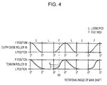
- An upper half of Fig. 4 shows a movement pattern of the cloth guide roller 16, whereas a lower half shows a movement pattern of the ground-warp tension roller 15. Moreover, the lower half is additionally provided with a dotted line which shows a movement pattern of the ground-warp tension roller 15 when the drive-changing means 40 is in a non-actuated mode.
- An angle ⁇ 0 indicates a rotational angle of a main shaft of the loom 1 when the output shaft m1s of the driving motor m1 is rotated clockwise by the angle ⁇ 1 from the state of loose-pick beating motion.
- the fast-pick beating position and the loose-pick beating position of the ground-warp tension roller 15 are the same between the actuated mode and the non-actuated mode of the drive-changing means 40, but the movement pattern for the shifting process of the ground-warp tension roller 15 is different between the two modes.
- An "F POSITION” in Fig. 4 refers to the positions of the ground-warp tension roller 15 and the cloth guide roller 16 for fast-pick beating motion
- an “L POSITION” refers to the positions of the ground-warp tension roller 15 and the cloth guide roller 16 for loose-pick beating motion.
- a rocking motion of the supporting lever 24 for shifting the ground-warp tension roller 15 is based on a movement of the connection part CP1 directly linked with the supporting lever 24 via the linking rod 26.
- the connection part CP1 revolves around the connection part CP6 in response to the rotation of the output shaft m1s.
- the relationship between the predetermined rotary phase of the output shaft m1s and the rocking position of the supporting lever 24 is constantly the same, such that the ground-warp tension roller 15 is constantly shifted to a position corresponding to each rotary phase of the output shaft m1s of the driving motor m1.
- a position of the ground-warp tension roller 15 corresponding to a certain rotary phase of the output shaft m1s of the driving motor m1 is always constant.
- the term "non-actuated mode" of the drive-changing means 40 refers to a state in which a rotary phase of the output shaft m2s is maintained so as to retain the rocking lever 42 at an initial position shown in Fig. 3A. Therefore, the non-actuated mode is different from a state in which the power of the drive-changing means 40 itself is turned off (i.e. a power-off state).
- connection part CP1 is moved by the auxiliary motor m2 via the linking lever 44 and the rocking lever 42 in addition to the above-referenced movement in the non-actuated mode.
- the movement of the connection part CP1 is a combination of a revolution around the connection part CP6 by means of the driving motor m1 and a revolution around the connection part CP3 by means of the auxiliary motor m2.
- the position of the connection part CP1 in this state is different from the position of the connection part CP1 on the trajectory line when the drive-changing means 40 is in a non-actuated mode.
- the rocking position of the supporting lever 24 i.e. the position of the ground-warp tension roller 15 directly linked with the connection part CP1 and the connection part CP2 is also different from the position thereof when the drive-changing means 40 is in a non-actuated mode.
- the ground-warp tension roller 15 is positioned closer towards the cloth fell CF by a distance x in comparison to the state in Fig. 3A in which the drive-changing means 40 is in a non-actuated mode.
- connection part CP1 the connection part CP2
- connection part CP3 the distance between the connection part CP3 and the connection part CP2 (i.e. the distance between the connection parts for the rocking lever 18 and the supporting lever 24) changes in accordance with an angle formed between the linking rod 22 and the linking rod 26. Therefore, the rocking position of the supporting lever 24 also changes in accordance with the position of the connection part CP1.
- connection part CP1 that affects the rocking position of the supporting lever 24 is changed in accordance with a rotary phase of the output shaft m2s of the auxiliary motor m2.
- the rotary phase of the output shaft m2s of the auxiliary motor m2 is set such that the ground-warp tension roller 15 is set to a desired position after each rotation in a reciprocation process of the driving motor m1 (i.e. each shifting in the reciprocation process of the ground-warp tension roller 15).
- the auxiliary motor m2 is driven under a driving pattern corresponding to the set rotary phase so that the ground-warp tension roller 15 can be driven in a movement pattern that is different from a movement pattern in which the ground-warp tension roller 15 is driven with only the driving motor m1.
- the driving pattern of the auxiliary motor m2 is set such that the shifting distance for the ground-warp tension roller 15 is set to a smaller amount for the first half of the cycle in order to compensate for an increase in warp tension caused by a shedding motion.
- the shifting distance is set to a larger amount for the second half so that the ground-warp tension roller 15 can properly reach its fast-pick beating position.
- the first embodiment is directed to an example in which the drive-changing means 40 is actuated to change the movement pattern for a shifting process of a terry motion member in order to compensate for fluctuation of warp tension caused by a shedding motion.
- the present invention is not limited to the changeability of the movement pattern, and may alternatively be applied to a changeability of the shifting distance of a terry motion member.
- the warp tension at the time of a fast-pick beating motion may change from the warp tension prior to the change in the weaving condition.
- a low warp tension may impair the beating property for inserted weft threads, whereas a high warp tension may cause the warp threads to break in response to an impact of a beating motion.
- the fast-pick beating position of the ground-warp tension roller 15 is set in correspondence with the tension of warp threads after the change in the weaving condition, and the auxiliary motor m2 is driven so that the position of the ground-warp tension roller 15 is different from the position thereof before the changing of the weaving condition.
- the driving pattern of the auxiliary motor m2 for changing the movement pattern of the ground-warp tension roller 15 as described in the first embodiment may include a plurality of set patterns including a pattern corresponding to the weaving condition to be changed.
- a desired driving pattern may be selected in accordance with the selected weaving condition so that the auxiliary motor m2 is driven on the basis of the selected driving pattern.
- the timing for starting the shifting process may also be changeable.
- the auxiliary motor m2 when the driving motor m1 is driven in a state where the ground-warp tension roller 15 is at its loose-pick or fast-pick beating position, the auxiliary motor m2 may be driven so that, in response to the rotation of the output shaft m1s, the connection part CP1 moves along a circular-arc line C which is centered on the connection part CP2 adjacent to one end of the supporting lever 24 and has the length of the linking rod 26 (i.e. the distance between the connection parts CP1 and CP2) as the radius. Consequently, the ground-warp tension roller 15 is prevented from being shifted from that position in response to the rotation of the output shaft m1s.
- a start timing for shifting a terry motion member is changeable.
- the linking means for linking the rocking lever 18 to the supporting lever 24 is defined by the two linking rods (linking members) 22 and 26 that are rotatably connected to each other.
- the drive-changing means 40 changes the position of the connection part CP1 so as to change the rocking position of the supporting lever 24 with respect to the predetermined rotary phase of the output shaft m1s.
- an effective length of the linking members may be changeable so that the distance between the connection parts can be changed. Consequently, this allows for the changeability of a driving mode of a terry motion member.
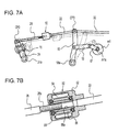
- the linking means for linking the rocking lever 18 to the supporting lever 24 mainly includes the linking rod 22 and a linking rod 28.
- the linking rod 22 and the linking rod 28 have drive-changing means 50 disposed therebetween.
- the drive-changing means 50 linearly links the linking rod 22 and the linking rod 28.
- the rocking lever 18 corresponding to the rocking member according to the present invention is provided with a rocking shaft 18a, such that the rocking lever 18 is rockably supported by the side frames of the loom 1 via the rocking shaft 18a.
- the rocking lever 18 is linked with the output shaft m1s of the driving motor m1 via a link 19 and a crank lever 17, and is rocked in response to a rotation of the output shaft m1s.
- the drive-changing means 50 changes an effective length of the linking rod 28, and includes a housing 52 fixed to an end of the linking rod 22 opposite to the end adjacent to the connection part CP3; a rotor 58 rotatably disposed inside the housing 52; and an exciting coil 54 disposed around a periphery of the rotor 58. Furthermore, a plurality of permanent magnets 56 facing the exciting coil 54 is attached to an outer peripheral surface of the rotor 58. Accordingly, in this example, a unit consisting of the exciting coil 54 and the permanent magnets 56 functions as the designated actuator according to the present invention.
- the rotor 58 is provided with a concentric through hole 58a extending longitudinally through the rotor 58.
- An inner periphery surface of the through hole 58a is provided with an internal thread portion.
- an end of the linking rod 28 opposite to the end adjacent to the connection part CP2 is provided with an external thread portion 28a.
- the rotor 58 is rotated by exciting the exciting coil 54 of the drive-changing means 50.
- an amount of insertion of the external thread portion 28a of the linking rod 28 with respect to the through hole 58a changes. Consequently, this changes the effective length of the linking rod 28, or more specifically, the length of the linking rod 28 between the drive-changing means 50 and the supporting lever 24 (connection part CP2), whereby the distance between the connection part CP3 of the rocking lever 18 and the connection part CP2 of the supporting lever 24 is changed.
- the rotor 58 rotated by the exciting coil 54 and the permanent magnets 56 corresponds to the driven member according to the present invention. Furthermore, since the amount of insertion of the linking rod 28 with respect to the through hole 58a changes in response to the rotation of the rotor 58, the linking rod 28 is displaced towards the drive-changing means 50 (towards the connection part CP3).
- the drive-changing means 50 when the drive-changing means 50 is actuated while the ground-warp tension roller 15 is being shifted by the driving motor m1, the movement of the connection part CP2 becomes different from the movement of the connection part CP3 driven by the driving motor m1.
- the driving mode of the ground-warp tension roller 15 can be changed to a desired mode.
- the linking rod 22 may be omitted.
- the drive-changing means 50 may be disposed at the end of the rocking lever 18 adjacent to connection part CP3.
- the rocking lever 18 and the supporting lever 24 may be linked to each other with a single linking member, such that the effective length of that single linking member is changeable.
- the drive-changing means 50 may alternatively be disposed at the end of the supporting lever 24 adjacent to the connection part CP2.
- two drive-changing means 50 may be disposed adjacent to the rocking lever 18 and the supporting lever 24, respectively.
- the rocking position of the supporting lever 24 with respect to the predetermined rotary phase of the output shaft m1s is changed by changing the distance between the connection part CP2 of the rocking lever 18 and the connection part CP3 of the supporting lever 24.
- the present invention is not limited to this technique.
- the rocking position of the supporting lever 24 with respect to the predetermined rotary phase of the output shaft m1s may be changed by changing the position of the connection part CP3 between the rocking lever 18 and a linking member in the longitudinal direction of the rocking lever 18.
- Fig. 8 illustrates another embodiment in which the rocking lever 18 and the supporting lever 24 are linked to each other with a single linking member defined by a linking lever 27.
- the rocking lever 18 is provided with a slit 18b extending in the longitudinal direction of the rocking lever 18.
- One end of the linking lever 27 is provided with a pin 27a which engages with the slit 18b, whereby the rocking lever 18 and the linking lever 27 are linked to each other.
- one of the drive-transmission mechanisms having the above-described structure is additionally provided with drive-changing means 60.
- the drive-changing means 60 has substantially the same structure as the drive-changing means 40, and includes a linking lever 64 serving as the driven member according to the present invention.
- the linking lever 64 is rotatably linked with the linking lever 27.
- a rotary phase of the output shaft m2s can be set for each relevant point in the shifting process of a terry motion member.
- a desired movement pattern of a terry motion member that is not limited by the driving of the driving motor m1 can be attained.
- Fig. 9 illustrates another embodiment in which drive-changing means 70 is provided for changing the position of a connection part between the rocking lever 18 and a linking rod 29.
- the drive-changing means 70 includes a screw member 72 that is disposed in the slit 18b of the rocking lever 18 and is rotated by driving means, not shown; and a driven member 74 having a through hole provided with an internal thread portion.
- the screw member 72 is screwed in the through hole so as to be engaged with the internal thread portion.
- the driven member 74 is connected to the linking rod 29, which is connected to the supporting lever 24. In other words, the rocking lever 18 and the linking rod 29 are linked to each other via the drive-changing means 70.
- the position of the connection part between the rocking lever 18 and the corresponding linking member is changed so as to change the rocking position of the rocking lever 18 with respect to the predetermined rotary phase of the output shaft m1s of the driving motor m1.
- the position of the connection part between the supporting lever 24 and the corresponding linking member may be changeable. This alternative embodiment achieves the same advantage as the embodiments shown in Figs. 8 and 9.
- the designated driving motor m1 is used as common driving means for driving the let-off-side and take-up-side terry motion members.
- the present invention is applicable to a loom in which the terry motion members are driven by a main shaft of the loom, or in other words, are driven by a main motor of the loom.
- the present invention is also applicable to the drive-transmission mechanism corresponding to the cloth guide roller 16 serving as the take-up-side terry motion member. In that case, the driving mode of the cloth guide roller 16 is changeable.
- the designated actuator serving as a driving source for the drive-changing means is not limited to a rotary-type actuator as in the above embodiments, and may alternatively be a linear motor.
Landscapes
- Engineering & Computer Science (AREA)
- Textile Engineering (AREA)
- Looms (AREA)
Abstract
Description
- The present invention relates to driving devices for terry motion members in cloth-shifting-type pile looms. In particular, the present invention relates to a driving device for let-off-side and take-up-side terry motion members included in a cloth-shifting-type pile loom, the driving device including drive-transmission mechanisms provided respectively for the two terry motion members and both linked to a driving shaft of common driving means provided for the two terry motion members. The drive-transmission mechanisms include a rocking member rocked by the driving means, supporting units respectively supporting the terry motion members, and linking means including at least one linking member that links the rocking member to the supporting units.
-
Japanese Unexamined Patent Application Publication No. 10-331053 - In the pile loom according to Patent Document 1, the let-off-side and take-up-side terry motion members are mechanically linked to each other. During a terry motion, the two terry motion members move while maintaining a fixed distance therebetween. In other words, a relationship between driving modes (driving amounts, drive timings, driving patterns, etc.) of the two terry motion members is always constant in a weaving operation.
- In a loom, a warp tension fluctuates in response to a shedding motion in each weaving cycle. However, the pile loom according to Patent Document 1 cannot actively compensate for the fluctuation of warp tension in each weaving cycle. As a result, the beating property for each inserted weft thread may be impaired due to an insufficient warp tension for a beating operation, or the warp threads may break if the warp tension at the time of a shedding motion reaches an excess value.
-
Japanese Unexamined Patent Application Publication No. 11-172552 Japanese Unexamined Patent Application Publication No. 2-47334 - According to a pile loom of Patent Document 3, the let-off-side and take-up-side terry motion members are not mechanically linked to each other, but are driven individually with designated driving motors (servomotors).
- According to Patent Documents 2 and 3, the driving modes of the let-off-side and take-up-side terry motion members can be changed individually to desired modes. Therefore, the let-off-side terry motion member can be driven in a movement pattern that compensates for the fluctuation of warp tension in the shifting process of the let-off-side terry motion member. Accordingly, this solves the problems existed in the pile loom of Patent Document 1.
- However, these conventional examples are still problematic in that a large magnitude of load is applied to the driving means. In other words, as is apparent from Patent Documents 2 and 3, in the prior art, the changeability of the individual driving modes of the let-off-side and take-up-side terry motion members to desired modes is generally achieved by driving the two terry motion members respectively with designated driving means. In a case where two sets of driving means and drive-transmission mechanisms provided respectively for the two terry motion members are independent of each other, the warp tension or weft tension is directly applied to the driving means, which means that a large magnitude of load is applied to the driving means.
- In detail, during a weaving operation, the let-off-side terry motion member receives a force corresponding to the warp tension, and the take-up-side terry motion member receives a force corresponding to the tension of a woven cloth. In a case where the drive-transmission mechanisms corresponding to the let-off-side and take-up-side terry motion members are mechanically linked to each other as in the pile loom of Patent Document 1, the forces applied to the terry motion members are balanced out. Thus, the magnitude of load applied to the driving means due to the tension mentioned above is small. In contrast, if two sets of driving means and drive-transmission mechanisms respectively corresponding to the let-off-side and take-up-side terry motion members are provided independent of each other, the forces acting on the terry motion members are directly applied to the driving means as a load.
- For example, in a case where designated motors are used as driving sources of the driving means, a large magnitude of load applied to the driving means may lead to, for example, an increase in power consumption or damaging of the driving means at an early stage of use. On the other hand, if the driving means includes the cam units as set forth in Patent Document 2, the rotary shafts of cams and the rocking shafts of the rocking levers, for example, may be subject to a large magnitude of load. This may lead to an abrasion or damaging of these shafts at an early stage of use.
- Accordingly, it is an object of the present invention to provide a driving device for let-off-side and take-up-side terry motion members in a cloth-shifting-type pile loom, which is given a capability to drive the let-off-side and take-up-side terry motion members under different driving modes while only a small magnitude of load is applied to driving means.
- The present invention provides a driving device for let-off-side and take-up-side terry motion members included in a cloth-shifting-type pile loom, the driving device including drive-transmission mechanisms provided respectively for the two terry motion members and both linked to a driving shaft of common driving means provided for the two terry motion members. The drive-transmission mechanisms include a rocking member rocked by the driving means, supporting units respectively supporting the terry motion members, and linking means including at least one linking member that links the rocking member to the supporting units. The driving device is characterized in that one of the drive-transmission mechanisms corresponding to the let-off-side or take-up-side terry motion member is additionally provided with drive-changing means having a designated actuator as a driving source and changing a rocking position of one of the supporting units included in the one of the drive-transmission mechanisms with respect to a certain rotary phase of the driving shaft. The drive-changing means is actuated in a shifting process of the let-off-side or take-up-side terry motion member.
- Furthermore, the drive-changing means may include a driven member connected to the linking means and driven by the actuator so as to move the at least one linking member included in the linking means, the movement of the one linking member changing a distance between a connection part for connecting the rocking member and the linking means and a connection part for connecting the one of the supporting units and the linking means.
- Furthermore, the at least one linking member of the linking means may include a first linking member and a second linking member. In that case, the driven member included in the drive-changing means may be connected to a connection part between the first linking member and the second linking member and may be driven by the actuator so as to change an angle formed between the first linking member and the second linking member.
- Furthermore, the one of the drive-transmission mechanisms may be capable of changing a connecting position of a connection part between the one of the supporting units and the linking means with respect to the one of the supporting units or a connecting position of a connection part between the rocking member and the linking means with respect to the rocking member. Moreover, the drive-changing means may include a driven member that is connected to the at least one linking member of the linking means whose connecting position with respect to the one of the supporting units or the rocking member is changeable, the driven member being driven by the actuator so as to change the connecting position.
- According to the present invention, the let-off-side and take-up-side terry motion members are driven by common driving means, and are linked to the driving shaft of the common driving means via the respective drive-transmission mechanisms. This implies that the two terry motion members are mechanically linked to each other. Accordingly, the forces acting on the terry motion members due to tension are balanced out, whereby the magnitude of load applied to the driving means as a result of these forces is small.
- Furthermore, in the present invention, one of the drive-transmission mechanisms corresponding to the let-off-side or take-up-side terry motion member is additionally provided with the drive-changing means, which has the designated actuator as a driving source and changes a rocking position of one of the supporting units with respect to a predetermined rotary phase of the driving shaft. Moreover, since the drive-changing means is actuated in a shifting process of the terry motion member, the driving mode of the terry motion member corresponding to the one of drive-transmission mechanisms driven based on the driving means is subject to a change by the drive-changing means. Accordingly, the driving modes of the two terry motion members are not limited to the driving mode based on the driving means. Instead, the driving mode for one of the terry motion members may be set to a desired mode independently of the driving mode for the other terry motion member. Accordingly, this effectively prevents the beating property from being impaired or the warp threads from breaking.
-
- Fig. 1 is a side view of a cloth-shifting-type pile loom according to a first embodiment of the present invention;
- Fig. 2 is a schematic diagram showing a relevant portion of the first embodiment according to the present invention;
- Figs. 3A and 3B are schematic diagrams showing a relevant portion of the first embodiment according to the present invention;
- Fig. 4 is a schematic diagram illustrating an operation of terry motion members according to the first embodiment of the present invention;
- Figs. 5A and 5B are schematic diagrams showing a relevant portion of another embodiment according to the present invention;
- Figs. 6A and 6B are schematic diagrams showing a relevant portion of another embodiment according to the present invention;
- Figs. 7A and 7B are side views showing a relevant portion of another embodiment according to the present invention;
- Fig. 8 is a side view showing a relevant portion of another embodiment according to the present invention; and
- Fig. 9 is a side view showing a relevant portion of another embodiment according to the present invention.
- Embodiments of the present invention will now be described with reference to the drawings.
- Figs. 1 to 4 illustrate a first embodiment according to the present invention. Figs. 1 and 2 show a cloth-shifting-type pile loom to which the present invention is applied. Specifically, Fig. 2 is a schematic diagram showing a relevant portion of the present invention. In Fig. 2, pile warp threads PT shown in Fig. 1 are not illustrated.
- Referring to Fig. 1, a cloth-shifting-type pile loom 1 includes an upper pile-warp beam 2 around which a plurality of pile warp threads PT are wound in a sheet-like manner, and a lower ground-warp beam 3 around which a plurality of ground warp threads GT are wound in a sheet-like manner. The pile warp threads PT are fed from the pile-warp beam 2 and are wound around two
guide rollers warp tension roller 7 disposed downstream of theguide rollers heald 8 and areed 5. - On the other hand, the ground warp threads GT are fed from the ground-warp beam 3 and are wound around a ground-
warp tension roller 15, which defines a let-off-side terry motion member. Similar to the pile warp threads PT, the ground warp threads GT guided by thetension roller 15 are then supplied to the cloth fell CF via theheald 8 and thereed 5. - Together with each inserted weft thread (not shown), the pile warp threads PT and the ground warp threads GT form the woven cloth W. The woven cloth W is subsequently guided by a
cloth guide roller 16, which defines a take-up-side terry motion member, towards a take-up roller 11 and guiderollers 12, 13 so as to be finally taken up by a cloth roller 14. - In the pile loom 1 shown in the drawings, the ground-warp tension roller 15 (i.e. the let-off-side terry motion member) and the cloth guide roller 16 (i.e. the take-up-side terry motion member) are driven together with a common designated driving motor m1 that is independent of a driving source for the pile loom 1. Each of the terry motion members is provided with a drive-transmission mechanism which connects the terry motion member to the driving motor m1.
- The driving motor m1 is fixed to a base frame of the pile loom 1, and has an output shaft m1s (driving shaft) to which a rocking
lever 18 serving as a rocking member is attached. The rockinglever 18 is used in common between a drive-transmission mechanism 20 corresponding to the ground-warp tension roller 15 and a drive-transmission mechanism 30 corresponding to thecloth guide roller 16. - The drive-
transmission mechanism 20 includes the rockinglever 18, a pair of supportinglevers 24 serving as a supporting unit for supporting the ground-warp tension roller 15, and linking means defined by linkingrods lever 18 and the supportinglevers 24. The supporting levers 24 are provided with a rockingshaft 24a, such that the supportinglevers 24 are supported respectively by opposite side frames (not shown) of the pile loom 1 in a rocking fashion via the rockingshaft 24a. The ground-warp tension roller 15 has its opposite ends respectively supported by the pair of supporting levers 24 (only one of which is shown in Fig. 1). Although there are actually two supportinglevers 24 in the present invention, since only one of the supportinglevers 24 is shown, the description below will refer to the one of the supportinglevers 24 in order to provide an easier understanding of the description. - As shown in the drawings, in the first embodiment, the linking means for linking the rocking
lever 18 and the supportinglever 24 includes the linkingrod 22 serving as a first linking member and the linkingrod 26 serving as a second linking member. The linkingrods rod 22 and the linkingrod 26 will be referred to as a connection part CP1 hereinafter. - One end of the supporting
lever 24 opposite to an end with the rockingshaft 24a is rotatably connected to the linkingrod 26. A connection part between the supportinglever 24 and the linkingrod 26 will be referred to as a connection part CP2 hereinafter. On the other hand, one end of the rockinglever 18 opposite to an end connected with the output shaft m1s of the driving motor m1 is rotatably connected to the linkingrod 22. A connection part between the rockinglever 18 and the linkingrod 22 will be referred to as a connection part CP3 hereinafter. The connection part CP3 is positionally adjustable in the longitudinal direction of the rockinglever 18. - The drive-
transmission mechanism 30 includes the rockinglever 18, a pair of supportinglevers 34 serving as a supporting unit for supporting thecloth guide roller 16, and a linkingrod 32 serving as a linking member for linking the rockinglever 18 and the supportinglevers 34. - Similar to the supporting
levers 24, the supportinglevers 34 are provided with a rockingshaft 34a, such that the supportinglevers 34 are supported respectively by the opposite side frames (not shown) of the pile loom 1 in a rocking fashion via the rockingshaft 34a. Thecloth guide roller 16 has its opposite ends respectively supported by the pair of supportinglevers 34. Similar to the supportinglevers 24, since only one of the supportinglevers 34 is shown, the description below will refer to the one of the supportinglevers 34 in order to provide an easier understanding of the description. One end of the supportinglever 34 opposite to an end provided with the rockingshaft 34a is rotatably connected to a first end of the linkingrod 32. A connection part between the supportinglever 34 and the linkingrod 32 will be referred to as a connection part CP5 hereinafter. On the other hand, a second end of the linkingrod 32 is rotatably connected to the end of the rockinglever 18 opposite to the end connected with the output shaft m1s. A connection part between the linkingrod 32 and the rockinglever 18 will be referred to as a connection part CP4 hereinafter. In other words, the supportinglever 34 is linked with the rockinglever 18 via asingle linking rod 32. The connection part CP4 is positionally adjustable in the longitudinal direction of the rockinglever 18. - In a driving device for the terry motion members in the cloth-shifting-type pile loom 1 according to the first embodiment described above, the drive-
transmission mechanism 20 corresponding to the ground-warp tension roller 15 (i.e. the let-off-side terry motion member) is additionally provided with drive-changingmeans 40. In detail, the drive-changingmeans 40 changes a driving mode of the ground-warp tension roller 15 driven by the driving motor m1. - The drive-changing
means 40 includes an auxiliary motor m2 serving as a designated actuator, a rockinglever 42 attached to an output shaft m2s of the auxiliary motor m2, and a linkinglever 44 rotatably connected to one end of the rockinglever 42 opposite to an end connected to the output shaft m2s. A connection part between the linkinglever 44 and the rockinglever 42 will be referred to as a connection part CP6 hereinafter. In this case, the linkinglever 44 that is driven by the auxiliary motor m2 via the rockinglever 42 corresponds to a driven member according to the present invention. One end of the linkinglever 44 opposite to an end adjacent to the connection part CP6 is rotatably connected to the connection part CP1 between the linkingrod 22 and the linkingrod 26. - According to the drive-changing
means 40, for example, when the output shaft m1s of the driving motor m1 is at a predetermined rotary phase, if the auxiliary motor m2 rocks the rockinglever 42 so as to shift the connection part CP1, an angle formed between the linkingrod 22 and the linkingrod 26 changes. Accordingly, this changes the distance between the connection part CP3 of the rockinglever 18 and the linkingrod 22 and the connection part CP2 of the supportinglever 24 and the linkingrod 26. As a result, a rocking position of the supportinglever 24 with respect to that rotary phase of the output shaft m1s is changed. - An operation of the driving device for the terry motion members will now be described with reference to Figs. 2 to 4. Specifically, Fig. 2 illustrates a state in which the drive-changing
means 40 is not actuated. Moreover, in Fig. 2, a solid line corresponds to a fast-pick beating motion, whereas a dashed line corresponds to a loose-pick beating motion. - In Fig. 2, when the output shaft m1s of the driving motor m1 is rotated clockwise by a predetermined amount from a state in which the two terry motion members are at their positions for loose-pick beating motion, the rocking
lever 18 is rocked from a position indicated by the dashed line to a position indicated by the solid line. - In response to the rocking motion of the rocking
lever 18, the supportinglever 34 linked with the rockinglever 18 via the linkingrod 32 is rocked around the rockingshaft 34a by an angle corresponding to the rocked angle of the rockinglever 18. Thus, thecloth guide roller 16 is shifted to a position for fast-pick beating motion indicated by the solid line. In this case, the rotational amount of the output shaft m1s is set to an amount necessary for shifting thecloth guide roller 16 from the loose-pick beating position to the fast-pick beating position. - Moreover, in response to the rocking motion of the rocking
lever 18, the connection part CP1 linked with the connection part CP3 via the linkingrod 22 is also shifted by an amount corresponding to the rocked angle of the rockinglever 18. In this case, since the drive-changingmeans 40 is in a non-actuated mode in Fig. 2, the rockinglever 42 is maintained in position by the auxiliary motor m2 so that the connection part CP6 between the rockinglever 42 and the linkinglever 44 is fixed in position. Consequently, the connection part CP1 revolves around the connection part CP6 along a predetermined trajectory line having the length of the linkinglever 44 as the radius. In response to the revolving motion of the connection part CP1, the supportinglever 24 linked with the connection part CP1 via the linkingrod 26 is rocked, thereby shifting the ground-warp tension roller 15 to its fast-pick beating position indicated by the solid line. - When the two
terry motion members reed 5. A fast-pick beating operation is then performed in this state. After the fast-pick beating operation, the driving motor m1 rotates the output shaft m1s counterclockwise so that the rockinglever 18 is driven in the reverse direction. Thus, the twoterry motion members warp tension roller 15 and thecloth guide roller 16 are shifted accordingly in a back-and-forth fashion. This reciprocates the cloth fell CF so as to form piles on the woven cloth W. - The supporting
lever 34, which supports thecloth guide roller 16, and the rockinglever 18 included in the drive-transmission mechanism 30 are directly linked with each other via the linkingrod 32. Thus, a driving mode of thecloth guide roller 16 is constantly determined by a driving mode of the driving motor m1. Therefore, the drive-start and drive-end timings of thecloth guide roller 16 are the same as the rotation timings of the output shaft m1s, and a movement pattern of thecloth guide roller 16 corresponds to the rotation of the output shaft m1s. In other words, a relationship between the driving mode of thecloth guide roller 16 and the rotation of the output shaft m1s is always constant. - On the other hand, because the drive-
transmission mechanism 20 corresponding to the ground-warp tension roller 15 is additionally provided with the drive-changingmeans 40, the driving mode of the ground-warp tension roller 15 is changeable. The changeability of the driving mode of the ground-warp tension roller 15 will be described below in detail with reference to Figs. 3 and 4. - Figs. 3A and 3B respectively show a comparison between a non-actuated mode of the drive-changing
means 40 and an actuated mode of the drive-changingmeans 40. In Figs. 3A and 3B, a dashed line corresponds to a fast-pick beating motion, a dotted line corresponds to a loose-pick beating motion, and a solid line corresponds to a state in which the output shaft m1s of the driving motor m1 is rotated clockwise by an angle θ1 from a state of loose-pick beating motion. - An upper half of Fig. 4 shows a movement pattern of the
cloth guide roller 16, whereas a lower half shows a movement pattern of the ground-warp tension roller 15. Moreover, the lower half is additionally provided with a dotted line which shows a movement pattern of the ground-warp tension roller 15 when the drive-changingmeans 40 is in a non-actuated mode. An angle θ0 indicates a rotational angle of a main shaft of the loom 1 when the output shaft m1s of the driving motor m1 is rotated clockwise by the angle θ1 from the state of loose-pick beating motion. - In Fig. 4, the fast-pick beating position and the loose-pick beating position of the ground-warp tension roller 15 (that is, a shifting amount of the ground-warp tension roller 15) are the same between the actuated mode and the non-actuated mode of the drive-changing
means 40, but the movement pattern for the shifting process of the ground-warp tension roller 15 is different between the two modes. An "F POSITION" in Fig. 4 refers to the positions of the ground-warp tension roller 15 and thecloth guide roller 16 for fast-pick beating motion, and an "L POSITION" refers to the positions of the ground-warp tension roller 15 and thecloth guide roller 16 for loose-pick beating motion. - A rocking motion of the supporting
lever 24 for shifting the ground-warp tension roller 15 is based on a movement of the connection part CP1 directly linked with the supportinglever 24 via the linkingrod 26. As described above, when the drive-changingmeans 40 is in a non-actuated mode (Fig. 3A), the connection part CP1 revolves around the connection part CP6 in response to the rotation of the output shaft m1s. Thus, the relationship between the predetermined rotary phase of the output shaft m1s and the rocking position of the supportinglever 24 is constantly the same, such that the ground-warp tension roller 15 is constantly shifted to a position corresponding to each rotary phase of the output shaft m1s of the driving motor m1. In other words, as long as the drive-transmission mechanism 20 is not structurally changed, a position of the ground-warp tension roller 15 corresponding to a certain rotary phase of the output shaft m1s of the driving motor m1 is always constant. For example, referring to Fig. 3A, when the output shaft m1s is rotated by the angle θ1 from a phase corresponding to a loose-pick beating motion, the ground-warp tension roller 15 will always be disposed at a position shown with the solid line. The term "non-actuated mode" of the drive-changingmeans 40 refers to a state in which a rotary phase of the output shaft m2s is maintained so as to retain the rockinglever 42 at an initial position shown in Fig. 3A. Therefore, the non-actuated mode is different from a state in which the power of the drive-changingmeans 40 itself is turned off (i.e. a power-off state). - In contrast, when the drive-changing
means 40 is actuated in the shifting process of the ground-warp tension roller 15, the connection part CP1 is moved by the auxiliary motor m2 via the linkinglever 44 and the rockinglever 42 in addition to the above-referenced movement in the non-actuated mode. Thus, the movement of the connection part CP1 is a combination of a revolution around the connection part CP6 by means of the driving motor m1 and a revolution around the connection part CP3 by means of the auxiliary motor m2. - In this case, in a state where the output shaft m1s is at a certain rotary phase in the shifting process of the ground-
warp tension roller 15, the position of the connection part CP1 in this state is different from the position of the connection part CP1 on the trajectory line when the drive-changingmeans 40 is in a non-actuated mode. Thus, the rocking position of the supporting lever 24 (i.e. the position of the ground-warp tension roller 15) directly linked with the connection part CP1 and the connection part CP2 is also different from the position thereof when the drive-changingmeans 40 is in a non-actuated mode. For example, referring to Fig. 3B, if the auxiliary motor m2 is driven such that the output shaft m2s of the auxiliary motor m2 is rotated by an angle θ2 at a point at which the output shaft m1s is rotated by the angle θ1 from the position corresponding to the loose-pick beating motion, the ground-warp tension roller 15 is positioned closer towards the cloth fell CF by a distance x in comparison to the state in Fig. 3A in which the drive-changingmeans 40 is in a non-actuated mode. - The above description is based on the relationship between the connection part CP1 and the connection part CP2. On the other hand, if the operation is described based on the connection part CP3, when the position of the connection part CP1 changes with respect to the position of the connection part CP3 corresponding to the predetermined rotary phase of the output shaft m1s, the distance between the connection part CP3 and the connection part CP2 (i.e. the distance between the connection parts for the rocking
lever 18 and the supporting lever 24) changes in accordance with an angle formed between the linkingrod 22 and the linkingrod 26. Therefore, the rocking position of the supportinglever 24 also changes in accordance with the position of the connection part CP1. - The position of the connection part CP1 that affects the rocking position of the supporting
lever 24 is changed in accordance with a rotary phase of the output shaft m2s of the auxiliary motor m2. Thus, the rotary phase of the output shaft m2s of the auxiliary motor m2 is set such that the ground-warp tension roller 15 is set to a desired position after each rotation in a reciprocation process of the driving motor m1 (i.e. each shifting in the reciprocation process of the ground-warp tension roller 15). The auxiliary motor m2 is driven under a driving pattern corresponding to the set rotary phase so that the ground-warp tension roller 15 can be driven in a movement pattern that is different from a movement pattern in which the ground-warp tension roller 15 is driven with only the driving motor m1. - For example, referring to Fig. 4, in each weaving cycle where the ground-
warp tension roller 15 is shifted from its loose-pick beating position to fast-pick beating position, the driving pattern of the auxiliary motor m2 is set such that the shifting distance for the ground-warp tension roller 15 is set to a smaller amount for the first half of the cycle in order to compensate for an increase in warp tension caused by a shedding motion. On the other hand, the shifting distance is set to a larger amount for the second half so that the ground-warp tension roller 15 can properly reach its fast-pick beating position. - The first embodiment is directed to an example in which the drive-changing
means 40 is actuated to change the movement pattern for a shifting process of a terry motion member in order to compensate for fluctuation of warp tension caused by a shedding motion. However, the present invention is not limited to the changeability of the movement pattern, and may alternatively be applied to a changeability of the shifting distance of a terry motion member. - For example, in a case where a weaving condition (ex. a shedding pattern, a weft density, or a rotational speed of the loom 1) is changed during an operation of the loom 1, the warp tension at the time of a fast-pick beating motion may change from the warp tension prior to the change in the weaving condition. For example, a low warp tension may impair the beating property for inserted weft threads, whereas a high warp tension may cause the warp threads to break in response to an impact of a beating motion. Referring to Figs. 5A and 5B, to solve these problems, the fast-pick beating position of the ground-
warp tension roller 15 is set in correspondence with the tension of warp threads after the change in the weaving condition, and the auxiliary motor m2 is driven so that the position of the ground-warp tension roller 15 is different from the position thereof before the changing of the weaving condition. - In response to the changed weaving condition, there is also a case where the warp tension changes in the shifting process of the terry motion members. Therefore, in that case, the driving pattern of the auxiliary motor m2 for changing the movement pattern of the ground-
warp tension roller 15 as described in the first embodiment may include a plurality of set patterns including a pattern corresponding to the weaving condition to be changed. A desired driving pattern may be selected in accordance with the selected weaving condition so that the auxiliary motor m2 is driven on the basis of the selected driving pattern. - According to the present invention, in addition to the movement pattern or the shifting distance of a terry motion member, the timing for starting the shifting process may also be changeable. In detail, referring to Figs. 6A and 6B, when the driving motor m1 is driven in a state where the ground-
warp tension roller 15 is at its loose-pick or fast-pick beating position, the auxiliary motor m2 may be driven so that, in response to the rotation of the output shaft m1s, the connection part CP1 moves along a circular-arc line C which is centered on the connection part CP2 adjacent to one end of the supportinglever 24 and has the length of the linking rod 26 (i.e. the distance between the connection parts CP1 and CP2) as the radius. Consequently, the ground-warp tension roller 15 is prevented from being shifted from that position in response to the rotation of the output shaft m1s. By utilizing this feature, a start timing for shifting a terry motion member is changeable. - In the above embodiments, the linking means for linking the rocking
lever 18 to the supportinglever 24 is defined by the two linking rods (linking members) 22 and 26 that are rotatably connected to each other. Moreover, the drive-changingmeans 40 changes the position of the connection part CP1 so as to change the rocking position of the supportinglever 24 with respect to the predetermined rotary phase of the output shaft m1s. However, the present invention is not limited to these embodiments. For example, an effective length of the linking members may be changeable so that the distance between the connection parts can be changed. Consequently, this allows for the changeability of a driving mode of a terry motion member. - Figs. 7A and 7B illustrate such an example. Referring to Fig. 7A, the linking means for linking the rocking
lever 18 to the supportinglever 24 mainly includes the linkingrod 22 and a linkingrod 28. The linkingrod 22 and the linkingrod 28 have drive-changingmeans 50 disposed therebetween. The drive-changingmeans 50 linearly links the linkingrod 22 and the linkingrod 28. In this example, the rockinglever 18 corresponding to the rocking member according to the present invention is provided with a rockingshaft 18a, such that the rockinglever 18 is rockably supported by the side frames of the loom 1 via the rockingshaft 18a. Moreover, the rockinglever 18 is linked with the output shaft m1s of the driving motor m1 via alink 19 and acrank lever 17, and is rocked in response to a rotation of the output shaft m1s. - The drive-changing
means 50 changes an effective length of the linkingrod 28, and includes a housing 52 fixed to an end of the linkingrod 22 opposite to the end adjacent to the connection part CP3; arotor 58 rotatably disposed inside the housing 52; and anexciting coil 54 disposed around a periphery of therotor 58. Furthermore, a plurality ofpermanent magnets 56 facing theexciting coil 54 is attached to an outer peripheral surface of therotor 58. Accordingly, in this example, a unit consisting of theexciting coil 54 and thepermanent magnets 56 functions as the designated actuator according to the present invention. - The
rotor 58 is provided with a concentric throughhole 58a extending longitudinally through therotor 58. An inner periphery surface of the throughhole 58a is provided with an internal thread portion. On the other hand, an end of the linkingrod 28 opposite to the end adjacent to the connection part CP2 is provided with anexternal thread portion 28a. By screwing theexternal thread portion 28a into the throughhole 58a of therotor 58, the linkingrod 28 becomes linked with the linkingrod 22 via the drive-changingmeans 50. - In this driving device for the terry motion members that is equipped with the drive-changing
means 50, therotor 58 is rotated by exciting theexciting coil 54 of the drive-changingmeans 50. In response to this rotation of therotor 58, an amount of insertion of theexternal thread portion 28a of the linkingrod 28 with respect to the throughhole 58a changes. Consequently, this changes the effective length of the linkingrod 28, or more specifically, the length of the linkingrod 28 between the drive-changingmeans 50 and the supporting lever 24 (connection part CP2), whereby the distance between the connection part CP3 of the rockinglever 18 and the connection part CP2 of the supportinglever 24 is changed. In this case, therotor 58 rotated by theexciting coil 54 and thepermanent magnets 56 corresponds to the driven member according to the present invention. Furthermore, since the amount of insertion of the linkingrod 28 with respect to the throughhole 58a changes in response to the rotation of therotor 58, the linkingrod 28 is displaced towards the drive-changing means 50 (towards the connection part CP3). - Accordingly, when the drive-changing
means 50 is actuated while the ground-warp tension roller 15 is being shifted by the driving motor m1, the movement of the connection part CP2 becomes different from the movement of the connection part CP3 driven by the driving motor m1. By utilizing this feature, the driving mode of the ground-warp tension roller 15 can be changed to a desired mode. - Alternatively, in Fig. 7, the linking
rod 22 may be omitted. In that case, the drive-changingmeans 50 may be disposed at the end of the rockinglever 18 adjacent to connection part CP3. Specifically, the rockinglever 18 and the supportinglever 24 may be linked to each other with a single linking member, such that the effective length of that single linking member is changeable. Furthermore, in that case, the drive-changingmeans 50 may alternatively be disposed at the end of the supportinglever 24 adjacent to the connection part CP2. As a further alternative, two drive-changingmeans 50 may be disposed adjacent to the rockinglever 18 and the supportinglever 24, respectively. - In the above embodiments, the rocking position of the supporting
lever 24 with respect to the predetermined rotary phase of the output shaft m1s is changed by changing the distance between the connection part CP2 of the rockinglever 18 and the connection part CP3 of the supportinglever 24. However, the present invention is not limited to this technique. Alternatively, for example, the rocking position of the supportinglever 24 with respect to the predetermined rotary phase of the output shaft m1s may be changed by changing the position of the connection part CP3 between the rockinglever 18 and a linking member in the longitudinal direction of the rockinglever 18. - Fig. 8 illustrates another embodiment in which the rocking
lever 18 and the supportinglever 24 are linked to each other with a single linking member defined by a linkinglever 27. Thus, the distance between the connection part CP2 and the connection part CP3 is fixed. The rockinglever 18 is provided with aslit 18b extending in the longitudinal direction of the rockinglever 18. One end of the linkinglever 27 is provided with apin 27a which engages with theslit 18b, whereby the rockinglever 18 and the linkinglever 27 are linked to each other. - In this embodiment, one of the drive-transmission mechanisms having the above-described structure is additionally provided with drive-changing
means 60. The drive-changingmeans 60 has substantially the same structure as the drive-changingmeans 40, and includes a linkinglever 64 serving as the driven member according to the present invention. The linkinglever 64 is rotatably linked with the linkinglever 27. - According to this structure, when the linking
lever 64 is moved by the auxiliary motor m2, thepin 27a of the linkinglever 27 linked with the linkinglever 64 slides along theslit 18b of the rockinglever 18. Thus, the distance between the connection part CP3 and the rockingshaft 18a changes, thereby changing the rocking angle of the rockinglever 18. Since this changes the rocking angle of the supportinglever 24 with respect to the rotational amount of the output shaft m1s of the driving motor m1, the rocking position of the supportinglever 24 with respect to the predetermined rotary phase of the output shaft m1s is changed from a rocking position prior to the actuation of the drive-changingmeans 60. Accordingly, by utilizing this changeability of the rocking angle, a rotary phase of the output shaft m2s can be set for each relevant point in the shifting process of a terry motion member. Thus, a desired movement pattern of a terry motion member that is not limited by the driving of the driving motor m1 can be attained. - Fig. 9 illustrates another embodiment in which drive-changing
means 70 is provided for changing the position of a connection part between the rockinglever 18 and a linkingrod 29. The drive-changingmeans 70 includes ascrew member 72 that is disposed in theslit 18b of the rockinglever 18 and is rotated by driving means, not shown; and a drivenmember 74 having a through hole provided with an internal thread portion. Thescrew member 72 is screwed in the through hole so as to be engaged with the internal thread portion. The drivenmember 74 is connected to the linkingrod 29, which is connected to the supportinglever 24. In other words, the rockinglever 18 and the linkingrod 29 are linked to each other via the drive-changingmeans 70. - According to this structure, when the
screw member 72 is rotated, the drivenmember 74 moves in the longitudinal direction of thescrew member 72, thereby changing the position of the connection part CP3 between the linkingrod 29 and the rockinglever 18. Consequently, the distance between the connection part CP3 and the rockingshaft 18a changes. This embodiment shown in Fig. 9 achieves the same advantage as the embodiment shown in Fig. 8. - In the embodiments shown in Figs. 8 and 9, the position of the connection part between the rocking
lever 18 and the corresponding linking member is changed so as to change the rocking position of the rockinglever 18 with respect to the predetermined rotary phase of the output shaft m1s of the driving motor m1. Alternatively, based on the same structure as above, the position of the connection part between the supportinglever 24 and the corresponding linking member may be changeable. This alternative embodiment achieves the same advantage as the embodiments shown in Figs. 8 and 9. - In the above embodiments, the designated driving motor m1 is used as common driving means for driving the let-off-side and take-up-side terry motion members. Alternatively, the present invention is applicable to a loom in which the terry motion members are driven by a main shaft of the loom, or in other words, are driven by a main motor of the loom.
- Although the above embodiments are directed to the ground-
warp tension roller 15 serving as the let-off-side terry motion member whose driving mode is changeable, the present invention is also applicable to the drive-transmission mechanism corresponding to thecloth guide roller 16 serving as the take-up-side terry motion member. In that case, the driving mode of thecloth guide roller 16 is changeable. - Furthermore, the designated actuator serving as a driving source for the drive-changing means is not limited to a rotary-type actuator as in the above embodiments, and may alternatively be a linear motor.
- The technical scope of the present invention is not limited to the above embodiments, and modifications are permissible within the scope and spirit of the present invention.
Claims (4)
- A driving device for let-off-side and take-up-side terry motion members (15, 16) included in a cloth-shifting-type pile loom (1), the driving device including drive-transmission mechanisms (20, 30) provided respectively for the two terry motion members (15, 16) and both linked to a driving shaft (m1s) of common driving means (m1) provided for the two terry motion members (15, 16), wherein the drive-transmission mechanisms (20, 30) include a rocking member (18) rocked by the driving means (m1), supporting units (24, 34) respectively supporting the terry motion members (15, 16), and linking means including at least one linking member (22, 26, 27, 28, 29, 32) that links the rocking member (18) to the supporting units (24, 34),
wherein the driving device is characterized in that one of the drive-transmission mechanisms (20, 30) corresponding to the let-off-side or take-up-side terry motion member (15, 16) is additionally provided with drive-changing means (40, 50, 60, 70) having a designated actuator (m2) as a driving source and changing a rocking position of one of the supporting units (24, 34) included in said one of the drive-transmission mechanisms (20, 30) with respect to a certain rotary phase of the driving shaft (m1s), the drive-changing means (40, 50, 60, 70) being actuated in a shifting process of the let-off-side or take-up-side terry motion member (15, 16). - The driving device according to Claim 1, wherein the drive-changing means (40, 50, 60, 70) includes a driven member (44, 58, 64, 74) connected to the linking means and driven by the actuator (m2) so as to move said at least one linking member (22, 26, 27, 28, 29, 32) included in the linking means, the movement of said at least one linking member (22, 26, 27, 28, 29, 32) changing a distance between a connection part (CP3) for connecting the rocking member (18) and the linking means and a connection part (CP2) for connecting said one of the supporting units (24, 34) and the linking means.
- The driving device according to Claim 2, wherein said at least one linking member (22, 26, 27, 28, 29, 32) of the linking means includes a first linking member (22) and a second linking member (26), and
wherein the driven member (44) included in the drive-changing means (40) is connected to a connection part (CP1) between the first linking member (22) and the second linking member (26) and is driven by the actuator (m2) to change an angle formed between the first linking member (22) and the second linking member (26). - The driving device according to Claim 1, wherein said one of the drive-transmission mechanisms (20, 30) is capable of changing a connecting position of a connection part (CP2) between said one of the supporting units (24, 34) and the linking means with respect to said one of the supporting units (24, 34) or a connecting position of a connection part (CP3) between the rocking member (18) and the linking means with respect to the rocking member (18), and
wherein the drive-changing means (40, 50, 60, 70) includes a driven member (44, 58, 64, 74) that is connected to said at least one linking member (22, 26, 27, 28, 29, 32) of the linking means whose connecting position with respect to said one of the supporting units (24, 34) or the rocking member (18) is changeable, the driven member (44, 58, 64, 74) being driven by the actuator (m2) so as to change said connecting position.
Applications Claiming Priority (1)
| Application Number | Priority Date | Filing Date | Title |
|---|---|---|---|
| JP2005163611A JP2006336160A (en) | 2005-06-03 | 2005-06-03 | Terry motion member drive mechanism in cloth moving pile loom |
Publications (2)
| Publication Number | Publication Date |
|---|---|
| EP1728905A2 true EP1728905A2 (en) | 2006-12-06 |
| EP1728905A3 EP1728905A3 (en) | 2008-11-19 |
Family
ID=36997903
Family Applications (1)
| Application Number | Title | Priority Date | Filing Date |
|---|---|---|---|
| EP06009841A Withdrawn EP1728905A3 (en) | 2005-06-03 | 2006-05-12 | Driving device for terry motion members in cloth-shifting-type pile loom |
Country Status (2)
| Country | Link |
|---|---|
| EP (1) | EP1728905A3 (en) |
| JP (1) | JP2006336160A (en) |
Cited By (1)
| Publication number | Priority date | Publication date | Assignee | Title |
|---|---|---|---|---|
| CN108823762A (en) * | 2018-09-04 | 2018-11-16 | 山东日发纺织机械有限公司 | A kind of cloth moves napping machine and cloth moves napping machine power mechanism |
Citations (3)
| Publication number | Priority date | Publication date | Assignee | Title |
|---|---|---|---|---|
| JPH0247334A (en) | 1988-07-08 | 1990-02-16 | Gebr Sulzer Ag | Operation of terry loom and terry loom |
| JPH10331053A (en) | 1997-05-30 | 1998-12-15 | Tsudakoma Corp | Pile forming apparatus |
| JPH11172552A (en) | 1997-12-09 | 1999-06-29 | Tsudakoma Corp | Warp tension correcting method for cloth-moving pile loom |
Family Cites Families (5)
| Publication number | Priority date | Publication date | Assignee | Title |
|---|---|---|---|---|
| JPS5038623Y2 (en) * | 1971-08-29 | 1975-11-07 | ||
| US5392817A (en) * | 1991-06-11 | 1995-02-28 | Sulzer Brothers Limited | Apparatus for altering the loop length of terry cloth |
| DE19537277C1 (en) * | 1995-10-06 | 1996-08-08 | Dornier Gmbh Lindauer | Pile height adjuster for terry cloth loom |
| JP3386407B2 (en) * | 1999-05-06 | 2003-03-17 | 津田駒工業株式会社 | Cloth moving pile forming device |
| JP3552595B2 (en) * | 1999-06-28 | 2004-08-11 | 津田駒工業株式会社 | Ground warp feeding tension device for pile loom of cloth moving type |
-
2005
- 2005-06-03 JP JP2005163611A patent/JP2006336160A/en active Pending
-
2006
- 2006-05-12 EP EP06009841A patent/EP1728905A3/en not_active Withdrawn
Patent Citations (3)
| Publication number | Priority date | Publication date | Assignee | Title |
|---|---|---|---|---|
| JPH0247334A (en) | 1988-07-08 | 1990-02-16 | Gebr Sulzer Ag | Operation of terry loom and terry loom |
| JPH10331053A (en) | 1997-05-30 | 1998-12-15 | Tsudakoma Corp | Pile forming apparatus |
| JPH11172552A (en) | 1997-12-09 | 1999-06-29 | Tsudakoma Corp | Warp tension correcting method for cloth-moving pile loom |
Cited By (2)
| Publication number | Priority date | Publication date | Assignee | Title |
|---|---|---|---|---|
| CN108823762A (en) * | 2018-09-04 | 2018-11-16 | 山东日发纺织机械有限公司 | A kind of cloth moves napping machine and cloth moves napping machine power mechanism |
| CN108823762B (en) * | 2018-09-04 | 2024-04-02 | 山东日发纺织机械有限公司 | Cloth moves fluffing device and cloth moves fluffing device power unit |
Also Published As
| Publication number | Publication date |
|---|---|
| JP2006336160A (en) | 2006-12-14 |
| EP1728905A3 (en) | 2008-11-19 |
Similar Documents
| Publication | Publication Date | Title |
|---|---|---|
| CN1022497C (en) | Terry method and loom having pile-forming elements | |
| US20020124901A1 (en) | Drive mechanism for shed forming components of a loom | |
| KR900001900A (en) | Sucker weaving method and circus loom | |
| JP2975387B2 (en) | Method and apparatus for driving a reed | |
| CN1077161C (en) | Device for controlling transverse movement of at least one thread in textile machine | |
| US20060207674A1 (en) | Method for operating a loom | |
| RU2274687C1 (en) | Actuation method for loom drive and shedding motion with separate drive means | |
| JP4973142B2 (en) | Warp tension controller for pile weaving loom | |
| EP1731640B1 (en) | Selvage device | |
| JP2007107128A (en) | Selvedge shedding device in loom | |
| EP3106554B1 (en) | Method for controlling shed opening of pile warp yarns in pile fabric loom | |
| KR20010023760A (en) | Thread controlling assembly | |
| JP6820679B2 (en) | A device for adjusting the tension of pile warp threads in a terry cloth loom. | |
| EP0768402B1 (en) | Device for programming rotary dobbies in weaving machines | |
| JP2006336160A (en) | Terry motion member drive mechanism in cloth moving pile loom | |
| EP1634983A2 (en) | Pile-formation method and pile-formation device in cloth-shifting-type pile loom | |
| US7594521B2 (en) | Device for driving a weaving frame in a weaving machine and a weaving machine provided with one or several such devices | |
| EP1710333A2 (en) | Driving device for terry motion members in cloth-shifting type pile loom | |
| EP1251194B1 (en) | Improved programming device for rotary dobbies of weaving machines | |
| CN100564629C (en) | Apparatus for executing a program of a rotary dobby in a weaving machine | |
| JP3377166B2 (en) | Pile forming equipment | |
| JPH11172552A (en) | Warp tension correcting method for cloth-moving pile loom | |
| EP0799919B1 (en) | Device for carrying out the programming of rotary dobbies in weaving machines | |
| JPH1121743A (en) | Pile formation system | |
| JPH10331053A (en) | Pile forming apparatus |
Legal Events
| Date | Code | Title | Description |
|---|---|---|---|
| PUAI | Public reference made under article 153(3) epc to a published international application that has entered the european phase |
Free format text: ORIGINAL CODE: 0009012 |
|
| AK | Designated contracting states |
Kind code of ref document: A2 Designated state(s): AT BE BG CH CY CZ DE DK EE ES FI FR GB GR HU IE IS IT LI LT LU LV MC NL PL PT RO SE SI SK TR |
|
| AX | Request for extension of the european patent |
Extension state: AL BA HR MK YU |
|
| PUAL | Search report despatched |
Free format text: ORIGINAL CODE: 0009013 |
|
| AK | Designated contracting states |
Kind code of ref document: A3 Designated state(s): AT BE BG CH CY CZ DE DK EE ES FI FR GB GR HU IE IS IT LI LT LU LV MC NL PL PT RO SE SI SK TR |
|
| AX | Request for extension of the european patent |
Extension state: AL BA HR MK YU |
|
| STAA | Information on the status of an ep patent application or granted ep patent |
Free format text: STATUS: THE APPLICATION IS DEEMED TO BE WITHDRAWN |
|
| 18D | Application deemed to be withdrawn |
Effective date: 20081202 |