EP1728719A1 - Article feeding mechanism, and bag-making and packaging machine - Google Patents
Article feeding mechanism, and bag-making and packaging machine Download PDFInfo
- Publication number
- EP1728719A1 EP1728719A1 EP04785649A EP04785649A EP1728719A1 EP 1728719 A1 EP1728719 A1 EP 1728719A1 EP 04785649 A EP04785649 A EP 04785649A EP 04785649 A EP04785649 A EP 04785649A EP 1728719 A1 EP1728719 A1 EP 1728719A1
- Authority
- EP
- European Patent Office
- Prior art keywords
- substantially cylindrical
- cylindrical member
- bag
- article
- making material
- Prior art date
- Legal status (The legal status is an assumption and is not a legal conclusion. Google has not performed a legal analysis and makes no representation as to the accuracy of the status listed.)
- Granted
Links
Images


Classifications
-
- B—PERFORMING OPERATIONS; TRANSPORTING
- B65—CONVEYING; PACKING; STORING; HANDLING THIN OR FILAMENTARY MATERIAL
- B65B—MACHINES, APPARATUS OR DEVICES FOR, OR METHODS OF, PACKAGING ARTICLES OR MATERIALS; UNPACKING
- B65B39/00—Nozzles, funnels or guides for introducing articles or materials into containers or wrappers
- B65B39/007—Guides or funnels for introducing articles into containers or wrappers
-
- B—PERFORMING OPERATIONS; TRANSPORTING
- B65—CONVEYING; PACKING; STORING; HANDLING THIN OR FILAMENTARY MATERIAL
- B65B—MACHINES, APPARATUS OR DEVICES FOR, OR METHODS OF, PACKAGING ARTICLES OR MATERIALS; UNPACKING
- B65B9/00—Enclosing successive articles, or quantities of material, e.g. liquids or semiliquids, in flat, folded, or tubular webs of flexible sheet material; Subdividing filled flexible tubes to form packages
- B65B9/10—Enclosing successive articles, or quantities of material, in preformed tubular webs, or in webs formed into tubes around filling nozzles, e.g. extruded tubular webs
- B65B9/20—Enclosing successive articles, or quantities of material, in preformed tubular webs, or in webs formed into tubes around filling nozzles, e.g. extruded tubular webs the webs being formed into tubes in situ around the filling nozzles
- B65B9/213—Enclosing successive articles, or quantities of material, in preformed tubular webs, or in webs formed into tubes around filling nozzles, e.g. extruded tubular webs the webs being formed into tubes in situ around the filling nozzles the web having intermittent motion
-
- B—PERFORMING OPERATIONS; TRANSPORTING
- B65—CONVEYING; PACKING; STORING; HANDLING THIN OR FILAMENTARY MATERIAL
- B65B—MACHINES, APPARATUS OR DEVICES FOR, OR METHODS OF, PACKAGING ARTICLES OR MATERIALS; UNPACKING
- B65B9/00—Enclosing successive articles, or quantities of material, e.g. liquids or semiliquids, in flat, folded, or tubular webs of flexible sheet material; Subdividing filled flexible tubes to form packages
- B65B9/10—Enclosing successive articles, or quantities of material, in preformed tubular webs, or in webs formed into tubes around filling nozzles, e.g. extruded tubular webs
- B65B9/20—Enclosing successive articles, or quantities of material, in preformed tubular webs, or in webs formed into tubes around filling nozzles, e.g. extruded tubular webs the webs being formed into tubes in situ around the filling nozzles
- B65B9/22—Forming shoulders; Tube formers
Definitions
- This invention relates to an article-supplying assembly and a packaging machine with the same.
- Snack foods such as potato chips are usually packaged by means of a packaging machine of the so-called vertical pillow type.
- a packaging machine of the vertical pillow type is provided with a former such as that described in Japanese Patent Unexamined Publication 7-315313 , and a funnel-shaped tube is placed above the former for guiding articles to be packaged.
- snack foods are coming to be sold in relatively small quantities with small bags. Even though the size of the bags is smaller, the size of food to be packed is same as before, so the ratio of the bag opening to the article size becomes smaller.
- Article-supplying assemblies for a vertical pillow type packaging machine are comprised of a first substantially cylindrical member, a guiding member, a second substantially cylindrical member, and a funnel member with funnel-shape.
- the first substantially cylindrical member extends in the vertical direction.
- the guiding member is connected to the first substantially cylindrical member with a ridgeline.
- the guiding member guides an elongated sheet of bag-making material from a back side to move downward along this first substantially cylindrical member.
- the second substantially cylindrical member is inserted into the inside of the first substantially cylindrical member.
- the funnel member which is connected to the second substantially cylindrical member with a junction line, extends upward from the second cylindrical member and receives articles falling from above.
- the junction line is positioned above the ridgeline, and the height difference between them is greater on the back side than on the front side which is the opposite side to the back side.
- the height difference between the junction line likely to make the bridge mentioned above and the ridge line on the back side is made to be greater than that of the front side. Therefore, the occurrence of articles being clogged inside the junction line becomes less, because the cross sectional area becomes larger where articles fall into surrounded by the junction line connecting the funnel member and the second substantially cylindrical member.
- this height difference be increasing gradually from the front side to the back side. Then, articles become even less clogged because the junction line runs along a smooth line.
- this height difference is equal to or greater than 30mm. From experiments, it seems to be indicated that articles clog much less if this range of values is employed.
- the height difference between the junction line and the ridgeline is equal to or less than 170mm. If this height difference is greater than 170mm, the sloping angle of funnel member becomes less, and articles bounce on the inside surface of the funnel member and the processing efficiency per hour (the number of bags packaged by the packaging machine) decreases.
- Article-supplying assemblies for a vertical pillow type packaging machine are comprised of a first substantially cylindrical member, a guiding member, a second substantially cylindrical member, and a funnel member.
- the first substantially cylindrical member extends in the vertical direction.
- the guiding member connected to the first substantially cylindrical member with a ridgeline guides an elongated sheet of bag-making material from a back side to move downward along this first substantially cylindrical member.
- the second substantially cylindrical member is inserted into the interior of the first substantially cylindrical member.
- the funnel member which is connected to the second substantially cylindrical member with a junction line, extends upward from the second substantially cylindrical member and receives articles falling from above.
- the highest point on the junction line is on the back side of the packaging machine, and the lowest point on it is on the front side. Further, the height difference between the highest point and the lowest point on the junction line is greater than 1.4 times the diameter of the second substantially cylindrical member.
- the ratio of the height difference between the highest point and the lowest point on the junction line with the diameter of the second substantially cylindrical member is equal to or greater than 1.4. Therefore, the occurrence of articles being clogged inside the area of the junction line becomes less because the cross sectional area where articles fall into surrounded by the junction line becomes considerably larger.
- Article-supplying assemblies for a vertical pillow type packaging machine are comprised of a first substantially cylindrical member, a guiding member, a second substantially cylindrical member, and a funnel member.
- the first substantially cylindrical member extends vertically downward.
- the guiding member is connected to the first substantially cylindrical member with a ridgeline.
- the guiding member guides an elongated sheet of bag-making material from a back side to move downward along this first substantially cylindrical member.
- the second substantially cylindrical member is inserted into the interior of the first substantially cylindrical member.
- the funnel member which is connected to the second substantially cylindrical member with a junction line, extends upward from the second substantially cylindrical member and receives articles falling from above. Further, the symmetry axis of the funnel member is tilted, by 2.5-12° in the vertical direction.
- the symmetry axis of the funnel member is tilted by 2.5-12° in the vertical direction. Therefore, the occurrence of articles being clogged inside the area of the junction line becomes less.
- the symmetry axis of the funnel member be tilted to the back side by 6-12°in the vertical direction.
- Article-supplying assemblies for a vertical pillow type packaging machine are comprised of a first substantially cylindrical member, a guiding member, a second substantially cylindrical member, and a funnel member.
- the first substantially cylindrical member extends vertically downward.
- the guiding member is connected to the first substantially cylindrical member with a ridgeline.
- the guiding member guides an elongated sheet of bag-making material from a back side to move downward along this first substantially cylindrical member.
- the second substantially cylindrical member is inserted into the interior of the first substantially cylindrical member.
- the funnel member which is connected to the second substantially cylindrical member with a junction line, extends upward from the second substantially cylindrical member and receives articles falling from above.
- the inner surface of the funnel member has a gently sloped portion on one side and a steeply sloped portion on the opposite side. The gently sloped portion makes a smaller angle with the horizontal direction than the steeply sloped portion by 5-24°
- the difference of the angle between the gently sloped portion and the steeply sloped portion on the inside surface of the funnel member is 5-24°. Therefore, the occurrence of articles being clogged inside the area of the junction line becomes less.
- the gently sloped portion makes a smaller angle with the horizontal direction than the steeply sloped portion by 12-24°.
- the gently sloped portion be on the back side of the inside of the funnel member.
- this invention relates not only to the article-supplying assemblies which are characterized as above, but also to the packaging machine with the same.
- the packaging machine related to this invention is comprised of the article-supplying assemblies of any of the above, a longitudinal sealer and a transverse sealer.
- the longitudinal sealer seals longitudinally mutually overlapping side edges of said bag-making material and makes it into a tubular form.
- the transverse sealer seals transversely the tubularly formed bag-making material and cuts the bag-making material to separate an individual packaged product.
- Fig. 1A shows a vertical pillow type packaging machine embodying this invention described, for example, in Japanese Patent Unexamined Publication 4-128105 .
- An elongated sheet of bag-making material (“film”) F unwound from a film roller (not shown) is made into a tubular form by means of a longitudinal sealer 50.
- a longitudinal sealer 50 As articles falling from above fill the interior of the tubularly formed film F, an upper edge part Fe of the film F is sealed by means of an end sealer 60 and cut across such that packaged products are produced continuously at a specified cycle time.
- the packaging machine employs pull-down belts 51 to pull the film F downward while holding side surfaces of the film F and the longitudinal sealer 50 seals over the mutually overlapping side edge parts of the film F in the longitudinal direction.
- the former 1 is comprised of a cylindrical portion 11 which is approximately cylindrical and has a C-shaped cross-section and a lapel-like guiding member 10 connected by welding to the cylindrical portion 11.
- the film F is guided by this guiding member 10 to the cylindrical portion 11 and transported intermittently downward along the inner surface from the position of the ridgeline 12 where the guiding member 10 and the cylindrical portion 11 join.
- the side of the packaging machine from which the guiding member 10 protrudes horizontally and on which the film F is received by the former 1 is hereinafter defined as its back side.
- the back side of the packaging machine is the right-hand side.
- the opposite side, which is to the left of Fig. 1A, is accordingly defined as its front side.
- a collector structure 2 is provided above the former 1, serving as a part of an article-supplying assembly for the packaging machine to collect the articles intermittently falling from above and to guide them into the interior of the cylindrical portion 11 of the former 1.
- the collector structure 2 is comprised of a substantially cylindrical-shaped tubular portion 21 and a funnel portion 22 of which the lower edge is welded to the upper edge of the tubular portion 21 along a junction line 23.
- the funnel portion 22 is in the shape of a funnel, its cross-sectional area becoming smaller in the from upper to lower part.
- the outer diameter of the tubular portion 21 is smaller than the inner diameter of the cylindrical portion 11 so as to be engagingly insertable into the cylindrical portion 11.
- the former 1 and the collector structure 2 are fastened by means of a fastening tool (not shown) such that they are both affixed in a correctly positioned relationship.
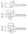
- the junction line 23 which welds and connects both tubular portion 21 and funnel portion 22 of the collector structure 2 mutually and the ridgeline 12 of the former 1 are arranged such that not only is the junction line 23 always above the ridgeline 12 but also the height difference between them (shown by letter Y in Figs. 2A and 2B) is greater on the back side than on the front side of the packaging machine. Furthermore, this height difference Y gradually increases from the front side to the back side, becoming the largest at the back side, also as shown in Figs. 2A and 2B.
- Table 1 shows clearly that clogging occurred frequently with the Comparison Example but it was less than half with Test Examples 1, 2 and 3. It seems to indicate that the value of Y is preferably equal to or greater than 30mm or more and the ratio h/D should be equal to or greater than about 1.6.
- the invention generally aims to cause some of the articles in a batch to start falling through the cylindrical portion 11 by reaching the junction line 23 much sooner than others, or to increase the effective sectional area through which the articles enter the cylindrical portion 11.
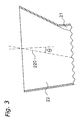
- Fig. 3 shows an example wherein the axis of symmetry 220 of the funnel portion 22 tilts in the direction of the back side such that the funnel member has the most gently sloped slide line on the back side and the most steeply sloped slide line on the front side.
- the tilting angle ⁇ of the axis of symmetry 220 is preferably in the range of 3°-12°.
- the tilting angle ⁇ of the axis of symmetry 220 is required to exceed 2.5°.
- the angle ⁇ of the axis of symmetry should be preferably 6°-12°.
- Fig. 4 shows still another embodiment of this invention wherein the inner surface of the funnel portion 22 has a thickened portion 225, say, on its back side, such that its inner surface is configured to have a pronouncedly more gently sloped upper portion 226, As can be understood by comparing Figs. 3 and 4, such a thickened portion 225 with the inner surface thus configured has the same effect on the articles being supplied thereonto as tilting the funnel portion 22 as a whole.
- ⁇ 1 the sloping angle of the funnel portion 22 on the front side
- fig.4 shows that the front side of the inner surface of the funnel portion 22 has a steeply sloped portion tilting from the horizontal surface and its back side has a gently sloped upper portion 226 tilting from the horizontal surface. Further, the sloping angle ⁇ 1 of the steeply sloped portion tilting from the horizontal surface is greater than the sloping angle ⁇ 2 of the gently sloped upper portion 226 from the horizontal surface, and the difference between them is 5°-24° (preferably 12°-24°).
- an article-supplying material designed such that articles do not become clogged so easily inside the article-guiding tube is available, and can be used effectively in a packaging machine of the vertical pillow type.
Landscapes
- Engineering & Computer Science (AREA)
- Mechanical Engineering (AREA)
- Containers And Plastic Fillers For Packaging (AREA)
- Supply Of Fluid Materials To The Packaging Location (AREA)
Abstract


Description
- This invention relates to an article-supplying assembly and a packaging machine with the same.
- Snack foods such as potato chips are usually packaged by means of a packaging machine of the so-called vertical pillow type. A packaging machine of the vertical pillow type is provided with a former such as that described in
Japanese Patent Unexamined Publication 7-315313 - If the bag opening becomes smaller, an accordingly smaller tube must be employed to fill the bag with articles falling from above. If the inner diameter of the tube is made smaller, however, the articles falling therethrough are more likely to become clogged, sometimes by forming what are commonly referred to as bridges. It now goes without saying that such bridges formed inside the tube prevent a smooth continuous packaging operation.
- It is therefore an object of this invention to provide article-supplying assemblies and a vertical-type packaging machine with such assembly designed such that articles do not become clogged easily inside the article-guiding material even while falling into a relatively small bag.
- Article-supplying assemblies for a vertical pillow type packaging machine according to the first aspect of this invention are comprised of a first substantially cylindrical member, a guiding member, a second substantially cylindrical member, and a funnel member with funnel-shape. The first substantially cylindrical member extends in the vertical direction. The guiding member is connected to the first substantially cylindrical member with a ridgeline. The guiding member guides an elongated sheet of bag-making material from a back side to move downward along this first substantially cylindrical member. The second substantially cylindrical member is inserted into the inside of the first substantially cylindrical member. The funnel member, which is connected to the second substantially cylindrical member with a junction line, extends upward from the second cylindrical member and receives articles falling from above. The junction line is positioned above the ridgeline, and the height difference between them is greater on the back side than on the front side which is the opposite side to the back side.
- Here, the height difference between the junction line likely to make the bridge mentioned above and the ridge line on the back side is made to be greater than that of the front side. Therefore, the occurrence of articles being clogged inside the junction line becomes less, because the cross sectional area becomes larger where articles fall into surrounded by the junction line connecting the funnel member and the second substantially cylindrical member.
- Note that it is desirable that this height difference be increasing gradually from the front side to the back side. Then, articles become even less clogged because the junction line runs along a smooth line.
- Moreover, it is desirable that this height difference is equal to or greater than 30mm. From experiments, it seems to be indicated that articles clog much less if this range of values is employed.
- In addition, it is desirable that the height difference between the junction line and the ridgeline is equal to or less than 170mm. If this height difference is greater than 170mm, the sloping angle of funnel member becomes less, and articles bounce on the inside surface of the funnel member and the processing efficiency per hour (the number of bags packaged by the packaging machine) decreases.
- Article-supplying assemblies for a vertical pillow type packaging machine according to the second aspect of this invention are comprised of a first substantially cylindrical member, a guiding member, a second substantially cylindrical member, and a funnel member. The first substantially cylindrical member extends in the vertical direction. The guiding member connected to the first substantially cylindrical member with a ridgeline guides an elongated sheet of bag-making material from a back side to move downward along this first substantially cylindrical member. The second substantially cylindrical member is inserted into the interior of the first substantially cylindrical member. The funnel member, which is connected to the second substantially cylindrical member with a junction line, extends upward from the second substantially cylindrical member and receives articles falling from above. The highest point on the junction line is on the back side of the packaging machine, and the lowest point on it is on the front side. Further, the height difference between the highest point and the lowest point on the junction line is greater than 1.4 times the diameter of the second substantially cylindrical member.
- Here, the ratio of the height difference between the highest point and the lowest point on the junction line with the diameter of the second substantially cylindrical member is equal to or greater than 1.4. Therefore, the occurrence of articles being clogged inside the area of the junction line becomes less because the cross sectional area where articles fall into surrounded by the junction line becomes considerably larger.
- Article-supplying assemblies for a vertical pillow type packaging machine according to the third aspect of this invention are comprised of a first substantially cylindrical member, a guiding member, a second substantially cylindrical member, and a funnel member. The first substantially cylindrical member extends vertically downward. The guiding member is connected to the first substantially cylindrical member with a ridgeline. The guiding member guides an elongated sheet of bag-making material from a back side to move downward along this first substantially cylindrical member. The second substantially cylindrical member is inserted into the interior of the first substantially cylindrical member. The funnel member, which is connected to the second substantially cylindrical member with a junction line, extends upward from the second substantially cylindrical member and receives articles falling from above. Further, the symmetry axis of the funnel member is tilted, by 2.5-12° in the vertical direction.
- Here, the symmetry axis of the funnel member is tilted by 2.5-12° in the vertical direction. Therefore, the occurrence of articles being clogged inside the area of the junction line becomes less.
- Note that it is desirable that the symmetry axis of the funnel member be tilted to the back side by 6-12°in the vertical direction.
- Article-supplying assemblies for a vertical pillow type packaging machine according to the fourth aspect of this invention are comprised of a first substantially cylindrical member, a guiding member, a second substantially cylindrical member, and a funnel member. The first substantially cylindrical member extends vertically downward. The guiding member is connected to the first substantially cylindrical member with a ridgeline. The guiding member guides an elongated sheet of bag-making material from a back side to move downward along this first substantially cylindrical member. The second substantially cylindrical member is inserted into the interior of the first substantially cylindrical member. The funnel member, which is connected to the second substantially cylindrical member with a junction line, extends upward from the second substantially cylindrical member and receives articles falling from above. The inner surface of the funnel member has a gently sloped portion on one side and a steeply sloped portion on the opposite side. The gently sloped portion makes a smaller angle with the horizontal direction than the steeply sloped portion by 5-24°
- Here, the difference of the angle between the gently sloped portion and the steeply sloped portion on the inside surface of the funnel member is 5-24°. Therefore, the occurrence of articles being clogged inside the area of the junction line becomes less.
- Note that it is desirable that the gently sloped portion makes a smaller angle with the horizontal direction than the steeply sloped portion by 12-24°.
- In addition, it is more desirable that the gently sloped portion be on the back side of the inside of the funnel member.
- Further, this invention relates not only to the article-supplying assemblies which are characterized as above, but also to the packaging machine with the same. The packaging machine related to this invention is comprised of the article-supplying assemblies of any of the above, a longitudinal sealer and a transverse sealer. The longitudinal sealer seals longitudinally mutually overlapping side edges of said bag-making material and makes it into a tubular form. And the transverse sealer seals transversely the tubularly formed bag-making material and cuts the bag-making material to separate an individual packaged product.
-
- Fig. 1A is a schematic side view of a packaging machine embodying this invention.
- Fig. 1B is a diagonal view of its former.
- Fig. 2A is schematic side view of a packaging machine for showing the positions of its collector structure and former.
- Fig. 2B is schematic side view of a packaging machine for showing the positions of its collector structure and former.
- Fig. 2C is schematic side view of a packaging machine for showing the positions of its collector structure and former.
- Fig. 3 is a schematic side view of a portion of another article-supplying assembly embodying this invention.
- Fig. 4 is a schematic side view of a portion of still another article-supplying assembly embodying this invention.
-
- 10
- guiding member
- 11
- cylindrical portion (first substantially cylindrical member)
- 12
- ridgeline
- 21
- tubular portion (second substantially cylindrical member)
- 22
- funnel portion (funnel member)
- 23
- junction line
- F
- film (sheet)
- Fig. 1A shows a vertical pillow type packaging machine embodying this invention described, for example, in
Japanese Patent Unexamined Publication 4-128105 longitudinal sealer 50. As articles falling from above fill the interior of the tubularly formed film F, an upper edge part Fe of the film F is sealed by means of anend sealer 60 and cut across such that packaged products are produced continuously at a specified cycle time. - It is by means of a former 1 that the film F is bent into a tubular form before the step using the
longitudinal sealer 50. The packaging machine employs pull-downbelts 51 to pull the film F downward while holding side surfaces of the film F and thelongitudinal sealer 50 seals over the mutually overlapping side edge parts of the film F in the longitudinal direction. - As shown in Fig. 1B, the former 1 is comprised of a
cylindrical portion 11 which is approximately cylindrical and has a C-shaped cross-section and a lapel-like guidingmember 10 connected by welding to thecylindrical portion 11. The film F is guided by this guidingmember 10 to thecylindrical portion 11 and transported intermittently downward along the inner surface from the position of theridgeline 12 where the guidingmember 10 and thecylindrical portion 11 join. For the convenience of description, the side of the packaging machine from which the guidingmember 10 protrudes horizontally and on which the film F is received by the former 1 is hereinafter defined as its back side. In Fig. 1A, therefore, the back side of the packaging machine is the right-hand side. The opposite side, which is to the left of Fig. 1A, is accordingly defined as its front side. - As shown in Figs. 2A and 2B, a
collector structure 2 is provided above the former 1, serving as a part of an article-supplying assembly for the packaging machine to collect the articles intermittently falling from above and to guide them into the interior of thecylindrical portion 11 of the former 1. Thecollector structure 2 is comprised of a substantially cylindrical-shapedtubular portion 21 and afunnel portion 22 of which the lower edge is welded to the upper edge of thetubular portion 21 along ajunction line 23. Thefunnel portion 22 is in the shape of a funnel, its cross-sectional area becoming smaller in the from upper to lower part. The outer diameter of thetubular portion 21 is smaller than the inner diameter of thecylindrical portion 11 so as to be engagingly insertable into thecylindrical portion 11. - The former 1 and the
collector structure 2 are fastened by means of a fastening tool (not shown) such that they are both affixed in a correctly positioned relationship. - According to one embodiment of the invention, the
junction line 23 which welds and connects bothtubular portion 21 andfunnel portion 22 of thecollector structure 2 mutually and theridgeline 12 of the former 1 are arranged such that not only is thejunction line 23 always above theridgeline 12 but also the height difference between them (shown by letter Y in Figs. 2A and 2B) is greater on the back side than on the front side of the packaging machine. Furthermore, this height difference Y gradually increases from the front side to the back side, becoming the largest at the back side, also as shown in Figs. 2A and 2B. - Effects of this aspect of the invention are explained next by way of three Test Examples (1,2 and 3) and one Comparison Example, Text Examples 1 and 2 being as shown in Fig. 2A with Y=50mm and 100mm, respectively, Test Example 3 being as shown in Fig. 2B with Y= 150mm and Comparison Example being as shown in Fig. 2C with the
ridgeline 12 nearly matching thejunction line 23, that is, Y=0. - On each of these Test Examples and Comparison, the ratio h/D of the height difference h between the highest point on the
junction line 23 on the back side and its lowest point on the front side with respect to the diameter D of thetubular portion 21 was measured as a parameter. These ratios were 1.3, 1.7, 2.3 and 3.1 as shown in Table 1 below. - For all of the Examples above, the same former 1 as shown in Fig. 1B for producing bags of width about 133mm (diameter being about 85mm) was used. The
collector structures 2 were all made of transparent resin materials such that a clogged condition could be visually observed. As articles to be packaged, about 20g of potato chips with diameters about equal to 50mm were dropped intermittently from a weighing apparatus placed above 500 times (for filling 500 bags) and the frequency of occurrence of clogging was recorded. The results of this test are also shown in Table 1.Table 1 Distance Y Height ratio h/D Frequency of clogging Comparison Example 0 1.3 12 times Test Example 1 50mm 1.7 5 times Test Example 2 100mm 2.3 5 times Test Example 3 150mm 3.1 Once - Table 1 shows clearly that clogging occurred frequently with the Comparison Example but it was less than half with Test Examples 1, 2 and 3. It seems to indicate that the value of Y is preferably equal to or greater than 30mm or more and the ratio h/D should be equal to or greater than about 1.6.
- Since Test Example 3 with Y=150mm shows a significant decrease in the frequency of clogging but the processing efficiency is low, it is necessary to set Y equal to or less than about 170mm (with h/D about equal to or less than 3.1) and it is generally desirable to set Y to be equal to or less than 150mm (with h/D about equal to or less than 2.8).
- In the above, the invention was explained by way of only a few examples but it should be clear to a person skilled in the art that many modifications and variations are possible within the scope of the invention. For example, there is no limitation intended for the diameter of the tube. Similar results may be expected for bags with width about 160mm or less (corresponding to the tube diameter of about 102mm or less). Thus, such modifications and variations are intended to be within the scope of the invention. The invention is also applicable for other kinds of pillow type packaging machines.
- As remarked above, there is more than one way to characterize article-supplying assemblies of this invention. Since the clogging would be more likely to take place if all of the articles of a batch (for example, each piece of potato chip) supplied started to fall through the
cylindrical portion 11 at the same time, the invention generally aims to cause some of the articles in a batch to start falling through thecylindrical portion 11 by reaching thejunction line 23 much sooner than others, or to increase the effective sectional area through which the articles enter thecylindrical portion 11. - One way of accomplishing this is to tilt the
funnel portion 22 as shown in Fig. 3 whereinreference numeral 220 indicates the axis of symmetry of the conically shaped (or funnel portion 22) and θ indicates the angle between this axis ofsymmetry 220 with the vertical direction. Fig. 3 shows an example wherein the axis ofsymmetry 220 of thefunnel portion 22 tilts in the direction of the back side such that the funnel member has the most gently sloped slide line on the back side and the most steeply sloped slide line on the front side. The tilting angle θ of the axis ofsymmetry 220 is preferably in the range of 3°-12°. Although some packaging machines of the prior art employ a funnel-shaped collector structure component with the axis of symmetry of its funnel-like shape tilted somewhat, it was at most the result of a design choice, not for the purpose of reducing the possibility of the occurrence of a clogged condition inside thecylindrical portion 11 and hence the tilting angle of its axis of symmetry was less than 2.5°. For the purpose of this invention, therefore, the tilting angle θ of the axis ofsymmetry 220 is required to exceed 2.5°.
Note that the angle θ of the axis of symmetry should be preferably 6°-12°. - Fig. 4 shows still another embodiment of this invention wherein the inner surface of the
funnel portion 22 has a thickenedportion 225, say, on its back side, such that its inner surface is configured to have a pronouncedly more gently slopedupper portion 226, As can be understood by comparing Figs. 3 and 4, such a thickenedportion 225 with the inner surface thus configured has the same effect on the articles being supplied thereonto as tilting thefunnel portion 22 as a whole. Thus, if the sloping angle of thefunnel portion 22 on the front side is indicated by symbol θ1 as shown in Fig. 4 and that of the more gently slopedupper portion 226 of the thickenedportion 225 is indicated by symbol θ2, their difference θ1 - θ2 is greater than 5° (=2 x 2.5°), or preferably greater than 12° (=2 x 6°), and less than, say, 24° (=2 x 12°). The inventors do not claim to know exactly why these embodiments work but merely state that they have the desired effect of reducing the occurrence of clogged conditions probably because the articles supplied together are forced to start their free falls at different timings, depending on the lateral direction (such as from the back side or the front side) in which they reach thecylindrical portion 11 to start falling freely. - Note that fig.4 shows that the front side of the inner surface of the
funnel portion 22 has a steeply sloped portion tilting from the horizontal surface and its back side has a gently slopedupper portion 226 tilting from the horizontal surface. Further, the sloping angle θ1 of the steeply sloped portion tilting from the horizontal surface is greater than the sloping angle θ2 of the gently slopedupper portion 226 from the horizontal surface, and the difference between them is 5°-24° (preferably 12°-24°). - In summary, many modifications and variations are possible within the scope of this invention and all such modifications and variations that may be apparent to a person skilled in the art are intended to be included within the scope of the invention.
- According to this invention, an article-supplying material designed such that articles do not become clogged so easily inside the article-guiding tube is available, and can be used effectively in a packaging machine of the vertical pillow type.
Claims (14)
- An article-supplying assembly for a vertical pillow type packaging machine, said assembly comprising:a first substantially cylindrical member extending vertically downward;a guiding member connected to the first substantially cylindrical member with a ridgeline and guiding an elongated sheet of bag-making material from a back side to move downward along said first substantially cylindrical member;a second substantially cylindrical member inserted into the interior of the first substantially cylindrical member; anda funnel member for receiving articles falling from above, which is connected to the second substantially cylindrical member with a junction line and extending upward from said second substantially cylindrical member;wherein said junction line is above said ridgeline, and the height difference between said junction line and said ridge line is greater on said back side than on a front side which is opposite to said back side.
- The article-supplying assembly as recited in claim 1 wherein said height difference increases gradually from said front side to said back side.
- The article-supplying assembly as recited in any of claims 1 or 2 wherein said height difference is equal to or greater than 30mm.
- The article-supplying assembly as recited in any of claims 1-3 wherein said height difference is equal to or less than 170mm.
- A packaging machine comprising:the article-supplying assembly as recited in any of claims 1-4;a longitudinal sealer for longitudinally sealing mutually overlapping side edges of said bag-making material into a tubular form; anda transverse sealer for transversely sealing said tubularly formed bag-making material and cutting said bag-making material transversely to separate an individual packaged product.
- An article-supplying assembly for a vertical pillow type packaging machine, said assembly comprising:a first substantially cylindrical member extending vertically downward;a guiding member connected to the first substantially cylindrical member with a ridgeline and guiding an elongated sheet of bag-making material from a back side to move downward along said first substantially cylindrical member;a second substantially cylindrical member inserted into the interior of the first substantially cylindrical member; anda funnel member for receiving articles falling from above, which is connected to the second substantially cylindrical member with a junction line and extending upward from said second substantially cylindrical member;wherein said junction line is at a highest point on said back side and at a lowest point on a front side which is opposite to said back side, and
the ratio of the height difference between said highest and lowest points of said junction line with respect to the diameter of said second substantially cylindrical member is equal to or greater than 1.4. - A packaging machine comprising:the article-supplying assembly as recited in claim 6;a longitudinal sealer for longitudinally sealing mutually overlapping side edges of said bag-making material into a tubular form; anda transverse sealer for transversely sealing said tubularly formed bag-making material and cutting said bag-making material transversely to separate an individual packaged product.
- An article-supplying assembly for a vertical pillow type packaging machine, said assembly comprising:a first substantially cylindrical member extending vertically downward;a guiding member connected to the first substantially cylindrical member with a ridgeline and guiding an elongated sheet of bag-making material from a back side to move downward along said first substantially cylindrical member;a second substantially cylindrical member inserted into the interior of the first substantially cylindrical member; anda funnel member for receiving articles falling from above, which is connected to the second substantially cylindrical member with a junction line and extending upward from said second substantially cylindrical member;wherein said funnel member is conically shaped with a symmetry axis that is tilted from the vertical direction by 2.5-12.0°.
- The article-supplying assembly as recited in claim 10 wherein said symmetry axis is tilted from the vertical direction by 6-12° to said back side.
- A packaging machine comprising:the article-supplying assembly as recited in claim 8 or 9;a longitudinal sealer for longitudinally sealing mutually overlapping side edges of said bag-making material into a tubular form; anda transverse sealer for transversely sealing said tubularly formed bag-making material and cutting said bag-making material transversely to separate an individual packaged product.
- An article-supplying assembly for a vertical pillow type packaging machine, said assembly comprising:a first substantially cylindrical member extending vertically downward;a guiding member connected to the first substantially cylindrical member with a ridgeline and guiding an elongated sheet of bag-making material from a back side to move downward along said first substantially cylindrical member;a second substantially cylindrical member inserted into the interior of the first substantially cylindrical member; anda funnel member for receiving articles falling from above, which is connected to the second substantially cylindrical member with a junction line and extending upward from said second substantially cylindrical member;wherein said funnel member has an inner surface configured so as to have a gently sloped portion on one side and a steeply sloped portion on an opposite side, said gently sloped portion making a smaller angle with the horizontal direction than said steeply sloped portion by 5-24°.
- The article-supplying assembly recited in claim 11 wherein said gently sloped portion makes a smaller angle with the horizontal direction than said steeply sloped portion by 12-24°.
- The article-supplying assembly recited as claim 11 or 12 wherein said gently sloped portion is on said back side in the inner surface of said funnel member.
- A packaging machine comprising:the article-supplying assembly recited in any of claims 11-13;a longitudinal sealer for longitudinally sealing mutually overlapping side edges of said bag-making material into a tubular form; anda transverse sealer for transversely sealing said tubularly formed bag-making material and cutting said bag-making material transversely to separate an individual packaged product.
Applications Claiming Priority (2)
| Application Number | Priority Date | Filing Date | Title |
|---|---|---|---|
| JP2004049575A JP2005239181A (en) | 2004-02-25 | 2004-02-25 | Vertical bag making and packaging machine |
| PCT/JP2004/013135 WO2005080204A1 (en) | 2004-02-25 | 2004-09-09 | Article feeding mechanism, and bag-making and packaging machine |
Publications (3)
| Publication Number | Publication Date |
|---|---|
| EP1728719A1 true EP1728719A1 (en) | 2006-12-06 |
| EP1728719A4 EP1728719A4 (en) | 2011-06-22 |
| EP1728719B1 EP1728719B1 (en) | 2014-02-12 |
Family
ID=34858262
Family Applications (1)
| Application Number | Title | Priority Date | Filing Date |
|---|---|---|---|
| EP04785649.7A Expired - Lifetime EP1728719B1 (en) | 2004-02-25 | 2004-09-09 | Article feeding mechanism, and bag-making and packaging machine |
Country Status (5)
| Country | Link |
|---|---|
| US (3) | US20050183399A1 (en) |
| EP (1) | EP1728719B1 (en) |
| JP (1) | JP2005239181A (en) |
| MX (1) | MXPA05009732A (en) |
| WO (1) | WO2005080204A1 (en) |
Families Citing this family (3)
| Publication number | Priority date | Publication date | Assignee | Title |
|---|---|---|---|---|
| JP5643674B2 (en) * | 2011-02-16 | 2014-12-17 | 株式会社イシダ | Packaging machine |
| JP5749939B2 (en) * | 2011-03-02 | 2015-07-15 | 株式会社イシダ | Bag making and packaging machine |
| MX390175B (en) * | 2016-08-15 | 2025-03-20 | Tna Australia Pty Ltd | PACKING UNIT. |
Family Cites Families (13)
| Publication number | Priority date | Publication date | Assignee | Title |
|---|---|---|---|---|
| US4501109A (en) * | 1982-05-03 | 1985-02-26 | Rexham Corporation | Packaging machine with improved web feeding system |
| US4566253A (en) * | 1984-05-23 | 1986-01-28 | Kliklok Corporation | Packaging system with interdigitating film advance |
| US4563862A (en) * | 1984-10-23 | 1986-01-14 | Kliklok Corporation | Package forming apparatus with combined holding and stripper mechanism |
| US4620409A (en) * | 1985-01-14 | 1986-11-04 | Kliklok Corporation | Packaging film feed with parallelogram belt support |
| DE3601104A1 (en) * | 1986-01-16 | 1987-07-23 | Bosch Gmbh Robert | DEVICE FOR PRODUCING BAG PACKS |
| JPH0767925B2 (en) * | 1990-09-10 | 1995-07-26 | 株式会社フジキカイ | Control method and apparatus for vertical bag-filling and packaging machine |
| JP3546968B2 (en) | 1994-05-30 | 2004-07-28 | 株式会社イシダ | Former used for packaging machine and its manufacturing method |
| US6428457B1 (en) * | 1995-09-29 | 2002-08-06 | Ishida Co., Ltd. | Former for a bag maker |
| AUPP228198A0 (en) * | 1998-03-11 | 1998-04-09 | Tna Australia Pty Limited | A packaging machine |
| JP4408510B2 (en) * | 1999-12-27 | 2010-02-03 | 株式会社イシダ | Bag making and packaging machine |
| JP2002361764A (en) * | 2001-06-06 | 2002-12-18 | Fuji Mach Co Ltd | Apparatus for manufacturing bag of film |
| JP2003112712A (en) * | 2001-10-05 | 2003-04-18 | Nitto Seiko Co Ltd | Film cylinder fusing device in automatic packaging machine |
| JP4427353B2 (en) * | 2004-02-26 | 2010-03-03 | 株式会社イシダ | Packaging machine |
-
2004
- 2004-02-25 JP JP2004049575A patent/JP2005239181A/en active Pending
- 2004-06-17 US US10/871,821 patent/US20050183399A1/en not_active Abandoned
- 2004-09-09 EP EP04785649.7A patent/EP1728719B1/en not_active Expired - Lifetime
- 2004-09-09 MX MXPA05009732A patent/MXPA05009732A/en active IP Right Grant
- 2004-09-09 WO PCT/JP2004/013135 patent/WO2005080204A1/en not_active Ceased
-
2005
- 2005-05-04 US US11/122,561 patent/US20050217216A1/en not_active Abandoned
-
2006
- 2006-12-01 US US11/607,415 patent/US20070074493A1/en not_active Abandoned
Also Published As
| Publication number | Publication date |
|---|---|
| WO2005080204A1 (en) | 2005-09-01 |
| EP1728719A4 (en) | 2011-06-22 |
| US20050217216A1 (en) | 2005-10-06 |
| JP2005239181A (en) | 2005-09-08 |
| EP1728719B1 (en) | 2014-02-12 |
| MXPA05009732A (en) | 2005-11-04 |
| US20050183399A1 (en) | 2005-08-25 |
| US20070074493A1 (en) | 2007-04-05 |
Similar Documents
| Publication | Publication Date | Title |
|---|---|---|
| US6945008B2 (en) | Packaging system with improved flow of articles | |
| US6648575B2 (en) | Device for feeding article to a blister band | |
| CN105189295B (en) | Filling method and packaging device for carrying out the filling method | |
| EP1112936A1 (en) | Bagging and packaging machine capable of filling a proper quantity of inert gas into bags | |
| EP2509901A1 (en) | Sorting device | |
| US20180118383A1 (en) | Thermo-forming packaging machine | |
| EP1728719B1 (en) | Article feeding mechanism, and bag-making and packaging machine | |
| EP0677450A1 (en) | An extruded net bag for packing bulk products, and a method for its manufacture | |
| US20180118381A1 (en) | Thermo-forming packaging machine | |
| CN109689511B (en) | Metering and packaging device | |
| US6619018B1 (en) | Bagging and packaging machine capable of sufficiently filling an inert gas into bags | |
| FR2770489A1 (en) | PROCESS FOR MANUFACTURING BAGS AND PACKAGING | |
| CN109250224B (en) | Thermoforming packaging machine with flexible packaging support | |
| EP1719704B1 (en) | Packaging machine | |
| EP0942870B1 (en) | Vacuum and gas-flush packaging device for filled pouches | |
| US5502956A (en) | Device for packaging products, in particular bread, in bags | |
| DE102009025089B4 (en) | Upright vacuum packaging machine | |
| WO2018047108A1 (en) | System and method for packaging powders | |
| US4446992A (en) | Fixed quantity feed apparatus | |
| CN206199722U (en) | Substandard product device for eliminating | |
| US3406494A (en) | Guiding arrangement for material to be wrapped between moving foils | |
| JPH04311416A (en) | Aligning device for cut article | |
| CN220974822U (en) | Chip collecting and discharging mechanism of liquid preparation packaging machine | |
| CN219750280U (en) | A detection of weighing remove device and packagine machine for packagine machine | |
| JP3311593B2 (en) | Shoot type weight sorter |
Legal Events
| Date | Code | Title | Description |
|---|---|---|---|
| PUAI | Public reference made under article 153(3) epc to a published international application that has entered the european phase |
Free format text: ORIGINAL CODE: 0009012 |
|
| 17P | Request for examination filed |
Effective date: 20041201 |
|
| AK | Designated contracting states |
Kind code of ref document: A1 Designated state(s): DE FR GB IT |
|
| DAX | Request for extension of the european patent (deleted) | ||
| RBV | Designated contracting states (corrected) |
Designated state(s): DE FR GB IT |
|
| A4 | Supplementary search report drawn up and despatched |
Effective date: 20110524 |
|
| RIC1 | Information provided on ipc code assigned before grant |
Ipc: B65B 39/00 20060101ALI20110518BHEP Ipc: B65B 9/10 20060101AFI20050906BHEP |
|
| 17Q | First examination report despatched |
Effective date: 20130227 |
|
| GRAP | Despatch of communication of intention to grant a patent |
Free format text: ORIGINAL CODE: EPIDOSNIGR1 |
|
| INTG | Intention to grant announced |
Effective date: 20130827 |
|
| GRAS | Grant fee paid |
Free format text: ORIGINAL CODE: EPIDOSNIGR3 |
|
| GRAA | (expected) grant |
Free format text: ORIGINAL CODE: 0009210 |
|
| AK | Designated contracting states |
Kind code of ref document: B1 Designated state(s): DE FR GB IT |
|
| REG | Reference to a national code |
Ref country code: GB Ref legal event code: FG4D |
|
| REG | Reference to a national code |
Ref country code: DE Ref legal event code: R096 Ref document number: 602004044386 Country of ref document: DE Effective date: 20140320 |
|
| REG | Reference to a national code |
Ref country code: DE Ref legal event code: R097 Ref document number: 602004044386 Country of ref document: DE |
|
| PLBE | No opposition filed within time limit |
Free format text: ORIGINAL CODE: 0009261 |
|
| STAA | Information on the status of an ep patent application or granted ep patent |
Free format text: STATUS: NO OPPOSITION FILED WITHIN TIME LIMIT |
|
| 26N | No opposition filed |
Effective date: 20141113 |
|
| REG | Reference to a national code |
Ref country code: DE Ref legal event code: R097 Ref document number: 602004044386 Country of ref document: DE Effective date: 20141113 |
|
| PG25 | Lapsed in a contracting state [announced via postgrant information from national office to epo] |
Ref country code: IT Free format text: LAPSE BECAUSE OF FAILURE TO SUBMIT A TRANSLATION OF THE DESCRIPTION OR TO PAY THE FEE WITHIN THE PRESCRIBED TIME-LIMIT Effective date: 20140212 |
|
| REG | Reference to a national code |
Ref country code: FR Ref legal event code: ST Effective date: 20150529 |
|
| PG25 | Lapsed in a contracting state [announced via postgrant information from national office to epo] |
Ref country code: FR Free format text: LAPSE BECAUSE OF NON-PAYMENT OF DUE FEES Effective date: 20140930 |
|
| PGFP | Annual fee paid to national office [announced via postgrant information from national office to epo] |
Ref country code: GB Payment date: 20220920 Year of fee payment: 19 Ref country code: DE Payment date: 20220920 Year of fee payment: 19 |
|
| REG | Reference to a national code |
Ref country code: DE Ref legal event code: R119 Ref document number: 602004044386 Country of ref document: DE |
|
| GBPC | Gb: european patent ceased through non-payment of renewal fee |
Effective date: 20230909 |
|
| PG25 | Lapsed in a contracting state [announced via postgrant information from national office to epo] |
Ref country code: GB Free format text: LAPSE BECAUSE OF NON-PAYMENT OF DUE FEES Effective date: 20230909 |
|
| PG25 | Lapsed in a contracting state [announced via postgrant information from national office to epo] |
Ref country code: GB Free format text: LAPSE BECAUSE OF NON-PAYMENT OF DUE FEES Effective date: 20230909 Ref country code: DE Free format text: LAPSE BECAUSE OF NON-PAYMENT OF DUE FEES Effective date: 20240403 |