EP1728677A1 - A seat assembly provided with a tip-down backrest for a motor vehicle - Google Patents
A seat assembly provided with a tip-down backrest for a motor vehicle Download PDFInfo
- Publication number
- EP1728677A1 EP1728677A1 EP05425389A EP05425389A EP1728677A1 EP 1728677 A1 EP1728677 A1 EP 1728677A1 EP 05425389 A EP05425389 A EP 05425389A EP 05425389 A EP05425389 A EP 05425389A EP 1728677 A1 EP1728677 A1 EP 1728677A1
- Authority
- EP
- European Patent Office
- Prior art keywords
- seat assembly
- backrest
- assembly according
- seat
- seat portion
- Prior art date
- Legal status (The legal status is an assumption and is not a legal conclusion. Google has not performed a legal analysis and makes no representation as to the accuracy of the status listed.)
- Granted
Links
- 230000000284 resting effect Effects 0.000 claims description 14
- 238000006073 displacement reaction Methods 0.000 claims description 8
- 230000005540 biological transmission Effects 0.000 claims description 5
- 230000009347 mechanical transmission Effects 0.000 claims description 2
- 238000013519 translation Methods 0.000 description 9
- 238000013459 approach Methods 0.000 description 6
- 230000014759 maintenance of location Effects 0.000 description 6
- 238000006243 chemical reaction Methods 0.000 description 4
- 238000011161 development Methods 0.000 description 3
- 239000011248 coating agent Substances 0.000 description 1
- 238000000576 coating method Methods 0.000 description 1
- 230000001419 dependent effect Effects 0.000 description 1
- 238000003780 insertion Methods 0.000 description 1
- 230000037431 insertion Effects 0.000 description 1
- 238000012986 modification Methods 0.000 description 1
- 230000004048 modification Effects 0.000 description 1
- 238000009877 rendering Methods 0.000 description 1
Images





Classifications
-
- B—PERFORMING OPERATIONS; TRANSPORTING
- B60—VEHICLES IN GENERAL
- B60N—SEATS SPECIALLY ADAPTED FOR VEHICLES; VEHICLE PASSENGER ACCOMMODATION NOT OTHERWISE PROVIDED FOR
- B60N3/00—Arrangements or adaptations of other passenger fittings, not otherwise provided for
- B60N3/10—Arrangements or adaptations of other passenger fittings, not otherwise provided for of receptacles for food or beverages, e.g. refrigerated
- B60N3/101—Arrangements or adaptations of other passenger fittings, not otherwise provided for of receptacles for food or beverages, e.g. refrigerated fixed
-
- B—PERFORMING OPERATIONS; TRANSPORTING
- B60—VEHICLES IN GENERAL
- B60N—SEATS SPECIALLY ADAPTED FOR VEHICLES; VEHICLE PASSENGER ACCOMMODATION NOT OTHERWISE PROVIDED FOR
- B60N2/00—Seats specially adapted for vehicles; Arrangement or mounting of seats in vehicles
- B60N2/02—Seats specially adapted for vehicles; Arrangement or mounting of seats in vehicles the seat or part thereof being movable, e.g. adjustable
- B60N2/04—Seats specially adapted for vehicles; Arrangement or mounting of seats in vehicles the seat or part thereof being movable, e.g. adjustable the whole seat being movable
- B60N2/06—Seats specially adapted for vehicles; Arrangement or mounting of seats in vehicles the seat or part thereof being movable, e.g. adjustable the whole seat being movable slidable
- B60N2/062—Seats specially adapted for vehicles; Arrangement or mounting of seats in vehicles the seat or part thereof being movable, e.g. adjustable the whole seat being movable slidable transversally slidable
-
- B—PERFORMING OPERATIONS; TRANSPORTING
- B60—VEHICLES IN GENERAL
- B60N—SEATS SPECIALLY ADAPTED FOR VEHICLES; VEHICLE PASSENGER ACCOMMODATION NOT OTHERWISE PROVIDED FOR
- B60N2/00—Seats specially adapted for vehicles; Arrangement or mounting of seats in vehicles
- B60N2/02—Seats specially adapted for vehicles; Arrangement or mounting of seats in vehicles the seat or part thereof being movable, e.g. adjustable
- B60N2/20—Seats specially adapted for vehicles; Arrangement or mounting of seats in vehicles the seat or part thereof being movable, e.g. adjustable the back-rest being tiltable, e.g. to permit easy access
- B60N2/206—Seats specially adapted for vehicles; Arrangement or mounting of seats in vehicles the seat or part thereof being movable, e.g. adjustable the back-rest being tiltable, e.g. to permit easy access to a position in which it can be used as a support for objects, e.g. as a tray
-
- B—PERFORMING OPERATIONS; TRANSPORTING
- B60—VEHICLES IN GENERAL
- B60N—SEATS SPECIALLY ADAPTED FOR VEHICLES; VEHICLE PASSENGER ACCOMMODATION NOT OTHERWISE PROVIDED FOR
- B60N2/00—Seats specially adapted for vehicles; Arrangement or mounting of seats in vehicles
- B60N2/75—Arm-rests
- B60N2/753—Arm-rests movable to an inoperative position
- B60N2/757—Arm-rests movable to an inoperative position in a recess of the back-rest
-
- B—PERFORMING OPERATIONS; TRANSPORTING
- B60—VEHICLES IN GENERAL
- B60N—SEATS SPECIALLY ADAPTED FOR VEHICLES; VEHICLE PASSENGER ACCOMMODATION NOT OTHERWISE PROVIDED FOR
- B60N2/00—Seats specially adapted for vehicles; Arrangement or mounting of seats in vehicles
- B60N2/75—Arm-rests
- B60N2/763—Arm-rests adjustable
- B60N2/77—Height adjustment
-
- B—PERFORMING OPERATIONS; TRANSPORTING
- B60—VEHICLES IN GENERAL
- B60N—SEATS SPECIALLY ADAPTED FOR VEHICLES; VEHICLE PASSENGER ACCOMMODATION NOT OTHERWISE PROVIDED FOR
- B60N2/00—Seats specially adapted for vehicles; Arrangement or mounting of seats in vehicles
- B60N2/75—Arm-rests
- B60N2/763—Arm-rests adjustable
- B60N2/773—Longitudinal adjustment
Definitions
- the present invention relates to a seat assembly provided with a backrest that can be tipped down for a motor vehicle.
- backrests that can be tipped down, which have the reverse side of the backrest (hereinafter referred to as retro-backrest) equipped with trays or containers to optimize the comfort of the driver and/or of adjacent passengers when said backrests are arranged laid down flat on their corresponding seats.
- retro-backrest the reverse side of the backrest
- a seat assembly of a configurable type that can undergo a transverse displacement with respect to the longitudinal direction of advance of the vehicle in a simple and fast way by acting at the side of said seat assembly, without at the same time ruling out the possibility of enabling other adjustments of position to be made (longitudinal adjustment, height adjustment, adjustment of the inclination of the backrest, adjustment of headrest, etc.).
- the aim of the present invention is to provide a seat assembly provided with a tip-down backrest for a vehicle which will enable the requirements set forth above to be achieved in a simple and inexpensive way.
- a seat assembly for a vehicle; the seat assembly comprising:
- said armrest comprises a resting body and connecting means for displacing said resting body between a stowed-away position, in which it is at least in part housed in said backrest, and an extracted position, in which it performs the function of armrest for a user.
- the reference number 1 designates, as a whole, a passenger compartment of a motor vehicle housing a front driving seat 2, of a type that is known and is not described in detail herein, and a front seat assembly 3 for passengers, set alongside the seat 2 in a transverse direction A, i.e. in a horizontal direction orthogonal to a longitudinal axis B of advance of the motor vehicle.
- the seat assembly 3 comprises an external side seat 4 and a central seat 5, set alongside one another, having the same frame 6 (described in detail in what follows), and comprising respective seat portions 7, 8 joined to one another, and respective backrests 9, 10, which are provided with respective headrests 11, 12 and have an inclination that is adjustable, by means of respective devices 13, 14, which are known and not described in detail herein (schematically illustrated in Figure 2), independently of one another, about an axis 15 parallel to the direction A.
- the backrests 9, 10 can be tipped down about the axis 15 independently of one another, from a raised position to a horizontal lowered position, in which they are laid down flat on the respective seat portions 7, 8, after manual actuation of respective controls 16, 17 for release (schematically illustrated in Figure 2), for example, levers carried by the backrests 9 and respectively, 10, for actuation of respective retention devices (known and not illustrated).
- the backrests 9, 10 are provided with respective retro-backrests, i.e. rigid elements for rear covering or coating (of which only that of the backrest 10 is visible), which define, in the lowered position, an equipped resting surface 18.
- the seat assembly 3 is configurable between a first functional position, in which the seat 4 can receive a passenger, whilst the seat 5 is moved up alongside the seat 2 with the backrest 10 set in the lowered position on the seat portion 8; and a second functional position, in which the seat 5 is set transversely at a distance from the seat 2 and can receive a corresponding passenger.
- the frame 6 comprises a bottom structure 20, which is set in a fixed transverse position and comprises two side legs 21, which can slide longitudinally along respective guides 22 (illustrated schematically), fixed on the floor of the passenger compartment 1.
- a releasable retention device (known and not illustrated), which can be unclamped by means of a manual action on a release device (also known and not illustrated), for example a lever carried by the structure 20 between the legs 21, to enable adjustment of the longitudinal position of the seat assembly 3.
- the structure 20 moreover comprises a front cross member 23 and a rear cross member 24, which are fixed to the legs 21 in longitudinal positions set at a distance from one another and carry, in fixed positions, respective guides 25 ( Figures 6 and 8) for guiding a top structure 26, which carries the seat portions 7, 8, in the direction A.
- the structure 26 comprises, in particular, a front cross member 27 set in front of the cross member 23, and a rear cross member 28 set behind the cross member 24.
- the cross members 27, 28 carry, in fixed positions, respective slides 29, which are slidably coupled to the guides 25 and are designed to be clamped with respect to the guides 25 by means of a further retention device (not illustrated) to keep the seat assembly 3 in either of the two functional positions.
- Said further retention device is released by manual actuation of a release control, in particular the control 17, in order to thus enable transverse translation of the structure 26 and hence of the seats 4, 5.
- the structure 26 then comprises two side rear brackets 31a, 31b and two central rear brackets 31c, 31d, which extend in cantilever fashion upwards with respect to the cross member 28.
- the pair of brackets 31a, 31c and the pair of brackets 31b, 31d carry hinged at their top ends, about the axis 15, respective structures 32, 33, which in turn carry the backrests 9, 10 and the headrests 11, 12.
- the structure 33 and hence the seat 5 have a smaller width, in the direction A, than do the structure 32 and the seat 4.
- the translation of the seats 4, 5 between the two aforesaid functional positions i.e. along a travel of approach towards the seat 2 or else a travel of withdrawal away from the seat 2, is approximately 63 mm.
- the translation, along at least one of said travels of approach and of withdrawal, is obtained in response to a displacement of the backrest 10 with respect to the seat portion 8, in particular in response to a rotation of the backrest 10 about the axis 15 away from and towards a vertical position through an angle greater than 25° forwards.
- the position of the backrest 10 and the transverse position of the seats 4, 5 are mutually dependent.
- a mechanical transmission 34 to bring about approach of the seats 4, 5 to the seat 2 when the backrest 10 is tipped down forwards on the seat portion 8, and to bring about withdrawal when the backrest 10 is tipped back towards its raised position.
- an electric motor either rotary or linear, could be provided, which translates the seats 4, 5 transversely in response to the displacement of the backrest 10.
- the transmission 34 is of the flexible-transmission type and comprises two Bowden cables, designated by 38 and 39, and a rocker lever 40, which can turn about the axis 15 jointly with respect to the structure 33, projects axially from the bracket 31b towards the seat 2, and comprises two radial arms 41, 42 diametrally opposite to one another.
- the cables 38, 39 comprise respective cores 43, 44 of fixed length, capable of flexing and of transmitting actions of tensile force, and respective sheaths 45, 46 of substantially fixed length, capable of flexing and of transmitting actions of pressure along their own length.
- the core 43 at its ends, is fixed to the arm 41 and to an appendage 47 carried in a fixed position by the structure 20, and traverses two appendages 48, 49 carried in fixed positions by the structure 26 and, respectively, by the bracket 31b, whilst the sheath 45 has its own ends coupled to the appendages 48, 49.
- the core 44 at its ends, is fixed to the arm 42 and to the appendage 48, and traverses two appendages 50, 51 carried in fixed positions by the structure 20 and, respectively, by the bracket 31b, where the appendages 50 and 47 are arranged on opposite sides of, and aligned to, the appendage 48 in the direction A.
- the sheath 46 instead, has its own ends coupled to the appendages 50, 51 and has a longitudinal development greater than the maximum distance between the appendages 50, 51.
- the lever 40 rotates forwards (in a counterclockwise direction as viewed in the figures) and pulls the core 44 towards the outside of the sheath 46 through the appendage 51, which exerts a reaction in regard to rotation of the lever 40 and transmits it to the sheath 46 itself.
- the sheath 46 in turn transmits said reaction throughout its length in the form of an action of pressure, up to the appendage 50.
- Said pressure behaves like an action of thrust of the sheath 46 against the appendage 50 in the direction A and consequently brings about the relative motion between the appendage 50 and the structure 26 that carries the appendage 51.
- the sheath 46 is progressively distended, i.e. it assumes a more linear configuration, between the appendages 50, 51, while maintaining the length of its own development substantially fixed.
- the sheath 45 slides on the core 43.
- the lever 40 rotates backwards (in a clockwise direction as viewed in the figures) and pulls the core 43 towards the outside of the sheath 45 through the appendage 49, which exerts a reaction in regard to rotation of the lever 40 and transmits it to the sheath 45 itself.
- the sheath 46 Whilst the core 43 is in tension, the sheath 46 in turn transmits the aforesaid reaction, throughout its length, in the form of an action of pressure, up to the appendage 48. Said pressure behaves like a thrust exerted by the sheath 45 in the direction A against the appendage 48, which consequently is displaced with respect to the core 43 towards the appendage 47.
- the appendage 51 During translation of the structure 26 towards the second operative position, the appendage 51 approaches the appendage 50, so that the sheath 46 progressively assumes a less linear configuration between the appendages 50, 51, while maintaining substantially fixed the length of its own development, whilst the core 44 slides in the sheath 46 itself.
- elastic means that are set between the structures 20 and 26 and are pre-loaded along one of the travels of approach and withdrawal to exert an action of thrust and bring about an automatic displacement along the other of the travels of approach and withdrawal of the seats 4, 5, when the slides 29 are released from the guides 25 by manual actuation of the control 17.
- the control 17 is coupled to the retention devices retaining the sliding of the slides 29 and the tipping of the backrest 10 by means of transmissions (not illustrated), which can be chosen from among the conventional ones available.
- the retro-backrest of the seat 5 is designated by the reference number 59, is coupled in a fixed position to the structure 33, in a way not described in detail, and has a plurality of trays or containers 60.
- Two armrests 61 are arranged on the retro-backrest 59, i.e. on the rear face of the backrest 10, in positions so that they are set alongside one another for resting of an arm of the driver of the seat 2 and, respectively, of the passenger of the seat 4.
- Each armrest 61 comprises an attachment structure defined by two longitudinal guides 63 fixed to the structure 33, a resting body 64, and a device 66 for connection of the body 64 to the guides 63. Thanks to the device 66, the body 64 is movable between a stowed-away position, in which it is housed in the backrest 10, in particular in a recess 67 of the retro-backrest 59, and an extracted position, in which a surface 68 of the body 64 functions as armrest for the user. In particular, when the body 64 is set in its stowed-away position, the surface 68 extends flush with or as a prolongation of the surface 18 ( Figure 10).
- the device 66 comprises a slide member 69 set between the guides 63 and slidably coupled to the guides 63 themselves to be able to displace the body 64 longitudinally forwards, i.e. towards the headrest 12, up to an advanced end-of-travel position.
- a retention and adjustment device (not illustrated), for example of the snap-action type or friction type, to retain the member 69 in the chosen longitudinal position in a releasable way.
- the device 66 moreover comprises an articulated quadrilateral 70 for displacing the body 64 in height with respect to the surface 18 between a lowered position corresponding to the aforesaid stowed-away position ( Figure 10), and a completely raised position (Figure 11).
- the recess 67 has a front wall 71, which prevents the body 64 from advancing along the guides 63 until it has been raised by a minimum height out of the recess 67 itself.
- the articulated quadrilateral 70 traverses a longitudinal slit 72 (Figure 1) made in an end wall 73 of the recess 67, and comprises a pair of rear connecting rods 74, set at a transverse distance apart from one another, and a front connecting rod 75, set centrally with respect to the connecting rods 74.
- the bottom ends of the pair of connecting rods 74 and of the connecting rod 75 are hinged to the member 69 about respective axes 76, 77 parallel to the axis 15.
- the top ends of the pair of connecting rods 74 and of the connecting rod 75 are hinged to a member 80 for supporting the body 64, about respective axes 81, 82, which are also parallel to the axis 15.
- a ratchet-like adjustment device 83 which comprises a toothing 84 made on the periphery of the top ends of the connecting rod 75, about the axis 82, and a pawl 85 hinged to the member 80 about an axis 86 parallel to the axis 82 and facing radially towards the toothing 84.
- the pawl 85 performs the function of strut and prevents rotation of the connecting rod 75 forwards (in a counterclockwise direction as viewed in Figure 12) and hence lowering of the body 64, when it engages any of the slots of the toothing 84.
- an elastic positioning element (not illustrated) to push the pawl 85 so that it engages the toothing 84, i.e. in a clockwise direction as viewed in Figure 12.
- the pawl 85 defines the end of a rocker 87 comprising, on the diametrally opposite side, an arm 88, which can be rotated (in a counterclockwise direction as viewed in Figure 12) by manual actuation of a control 90, in particular a lever, to move the pawl 85 away from the toothing 84 upwards, so as to leave the body 64 free to be lowered.
- a control 90 in particular a lever
- the lever 90 covers the rear part of an opening 91 made through the surface 68, and can be rotated manually, in a clockwise direction as viewed in Figure 12, to push the arm 88 downwards and thus disengage the pawl 85, by insertion of one's fingers through the uncovered front part of the opening 91.
- the seat assembly 3 In use, when it is necessary to carry two passengers on the seat assembly 3, the latter is brought into the second operative position, by simply raising the backrest 10, so as to have more space in the direction A for the passenger sitting on the seat 5.
- the seats 4, 5 can be displaced into the first functional position by sending the backrest 10 down: in this way, the surface 18 defined by the retro-backrest 59 contributes to rendering the journey more comfortable for the driver and the passenger on the seat 4, and at the same time the passenger on the seat 4 has available more space at the side between himself and the door (not illustrated) alongside the seat assembly 3.
- the armrests 61 arranged on, or carried by, the rear face of the backrest 10 can be raised from their stowed-away position, to contribute to improved ergonomics in the passenger compartment 1 on the front seats.
- the positions of the resting bodies 64 can be adapted to drivers and passengers of different size/height, independently of the longitudinal position of the structure 20 along the guides 22 located on the floor. From the foregoing it appears evident how the armrest 61 is located in a position that bestows particular compactness upon the seat assembly 3, can be adjusted in a simple way to achieve maximum ergonomics, is itself relatively simple, and has a limited number of pieces.
- the seat assembly 3 enables a good compromise to be achieved between ergonomics, comfort and number of passengers carried, thanks to the transverse translation of the seats 4, 5, and is configurable in an extremely simple way, thanks to the fact that the same transverse translation is obtained in response to a displacement of the backrest 10.
- the transmission 34 provided to achieve the transverse translation is, moreover, relatively simple, inexpensive, and reliable.
- the characteristics of the seat assembly 3 moreover afford a solution that particularly compact as well as being flexible, and can advantageously be applied not just in vehicles having three front seats, as described above by way of example, but also in vehicles with single seats, instead of double seats, and/or is applicable to rear seats, instead of front seats.
- an electric motor for tipping the backrest 10 about the axis 15, instead of providing a forward/backward tipping of a manual type, but always with an angular displacement in response to which at least one between the seats 4, 5 translates transversely.
- connection devices different from the ones described by way of example for connecting the body 64 to the backrest 10 in a movable way.
Landscapes
- Engineering & Computer Science (AREA)
- Transportation (AREA)
- Mechanical Engineering (AREA)
- Aviation & Aerospace Engineering (AREA)
- Physics & Mathematics (AREA)
- Thermal Sciences (AREA)
- Seats For Vehicles (AREA)
Abstract
Description
- The present invention relates to a seat assembly provided with a backrest that can be tipped down for a motor vehicle.
- In the passenger compartments of motor vehicles, it is known to use seats provided with backrests that can be tipped down, which have the reverse side of the backrest (hereinafter referred to as retro-backrest) equipped with trays or containers to optimize the comfort of the driver and/or of adjacent passengers when said backrests are arranged laid down flat on their corresponding seats.
- There is currently felt the need to provide a seat assembly of the type just described that carries at least one armrest set alongside for increasing the comfort of a user, and that will present low encumbrance and, preferably, a relatively small number of components.
- Preferably, there is felt the need to provide a seat assembly of a configurable type that can undergo a transverse displacement with respect to the longitudinal direction of advance of the vehicle in a simple and fast way by acting at the side of said seat assembly, without at the same time ruling out the possibility of enabling other adjustments of position to be made (longitudinal adjustment, height adjustment, adjustment of the inclination of the backrest, adjustment of headrest, etc.).
- The aim of the present invention is to provide a seat assembly provided with a tip-down backrest for a vehicle which will enable the requirements set forth above to be achieved in a simple and inexpensive way.
- According to the present invention a seat assembly is provided for a vehicle; the seat assembly comprising:
- a. at least one seat portion;
- b. at least one backrest, which is movable with respect to said seat portion between a raised position and a lowered position in which it is laid down flat on said seat portion; and
- c. an armrest (61);
- Preferably, said armrest comprises a resting body and connecting means for displacing said resting body between a stowed-away position, in which it is at least in part housed in said backrest, and an extracted position, in which it performs the function of armrest for a user.
- For a better understanding of the present invention there is now described a preferred embodiment thereof, purely by way of non-limiting example, with reference to the attached drawings, wherein:
- Figure 1 is a perspective view of a preferred embodiment of a seat assembly provided with a backrest that can be tipped down for a vehicle built according to the present invention and set in a first functional position;
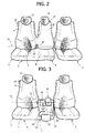
- Figure 2 is a front view of the seat assembly of Figure 1 set in a second functional position;
- Figure 3 is a front view of the seat assembly of Figure 1 set in the first functional position;
- Figures 4 and 5 are perspective views, at an enlarged scale, of a frame of the seat assembly of Figure 1, set in the first functional position and, respectively, in the second functional position;
- Figures 6 and 7 are, respectively, a perspective view from beneath and a side view of a detail, at an enlarged scale, of Figure 4;
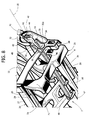
- Figures 8 and 9 are, respectively, a perspective view from beneath and a side view of a detail, at an enlarged scale, of Figure 5;
- Figure 10 shows, in perspective view and at an enlarged scale, a retro-backrest of the seat assembly of Figure 1;
- Figure 11 is a perspective view, at an even further enlarged scale, of an armrest of Figure 10, set in a completely raised position; and
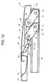
- Figure 12 is a side view, with parts removed for reasons of clarity, of the armrest of Figure 11, set in a different operative position.
- In Figure 1, the
reference number 1 designates, as a whole, a passenger compartment of a motor vehicle housing afront driving seat 2, of a type that is known and is not described in detail herein, and afront seat assembly 3 for passengers, set alongside theseat 2 in a transverse direction A, i.e. in a horizontal direction orthogonal to a longitudinal axis B of advance of the motor vehicle. - The
seat assembly 3 comprises anexternal side seat 4 and acentral seat 5, set alongside one another, having the same frame 6 (described in detail in what follows), and comprisingrespective seat portions respective backrests respective headrests respective devices axis 15 parallel to the direction A. - The
backrests axis 15 independently of one another, from a raised position to a horizontal lowered position, in which they are laid down flat on therespective seat portions respective controls backrests 9 and respectively, 10, for actuation of respective retention devices (known and not illustrated). - In particular, the
backrests backrest 10 is visible), which define, in the lowered position, an equippedresting surface 18. - With reference to Figures 2 and 3, the
seat assembly 3 is configurable between a first functional position, in which theseat 4 can receive a passenger, whilst theseat 5 is moved up alongside theseat 2 with thebackrest 10 set in the lowered position on theseat portion 8; and a second functional position, in which theseat 5 is set transversely at a distance from theseat 2 and can receive a corresponding passenger. - With reference to Figures 4 and 5, the
frame 6 comprises abottom structure 20, which is set in a fixed transverse position and comprises twoside legs 21, which can slide longitudinally along respective guides 22 (illustrated schematically), fixed on the floor of thepassenger compartment 1. To keep thestructure 20 in a fixed longitudinal position along theguides 22, there is provided a releasable retention device (known and not illustrated), which can be unclamped by means of a manual action on a release device (also known and not illustrated), for example a lever carried by thestructure 20 between thelegs 21, to enable adjustment of the longitudinal position of theseat assembly 3. - The
structure 20 moreover comprises afront cross member 23 and arear cross member 24, which are fixed to thelegs 21 in longitudinal positions set at a distance from one another and carry, in fixed positions, respective guides 25 (Figures 6 and 8) for guiding atop structure 26, which carries theseat portions - The
structure 26 comprises, in particular, afront cross member 27 set in front of thecross member 23, and arear cross member 28 set behind thecross member 24. Thecross members respective slides 29, which are slidably coupled to theguides 25 and are designed to be clamped with respect to theguides 25 by means of a further retention device (not illustrated) to keep theseat assembly 3 in either of the two functional positions. Said further retention device is released by manual actuation of a release control, in particular thecontrol 17, in order to thus enable transverse translation of thestructure 26 and hence of theseats - The
structure 26 then comprises two siderear brackets rear brackets cross member 28. The pair ofbrackets brackets axis 15,respective structures backrests headrests structure 33 and hence theseat 5 have a smaller width, in the direction A, than do thestructure 32 and theseat 4. - With reference to Figures 2 and 3, the translation of the
seats seat 2 or else a travel of withdrawal away from theseat 2, is approximately 63 mm. The translation, along at least one of said travels of approach and of withdrawal, is obtained in response to a displacement of thebackrest 10 with respect to theseat portion 8, in particular in response to a rotation of thebackrest 10 about theaxis 15 away from and towards a vertical position through an angle greater than 25° forwards. In other words, the position of thebackrest 10 and the transverse position of theseats - According to the preferred embodiment illustrated in Figures 4-9, there is provided a
mechanical transmission 34 to bring about approach of theseats seat 2 when thebackrest 10 is tipped down forwards on theseat portion 8, and to bring about withdrawal when thebackrest 10 is tipped back towards its raised position. However, according to one solution (not illustrated), an electric motor, either rotary or linear, could be provided, which translates theseats backrest 10. - According to what is illustrated in Figures 4-9, the
transmission 34 is of the flexible-transmission type and comprises two Bowden cables, designated by 38 and 39, and arocker lever 40, which can turn about theaxis 15 jointly with respect to thestructure 33, projects axially from thebracket 31b towards theseat 2, and comprises tworadial arms - The
cables respective cores respective sheaths core 43, at its ends, is fixed to thearm 41 and to anappendage 47 carried in a fixed position by thestructure 20, and traverses twoappendages structure 26 and, respectively, by thebracket 31b, whilst thesheath 45 has its own ends coupled to theappendages - In turn, the
core 44, at its ends, is fixed to thearm 42 and to theappendage 48, and traverses twoappendages structure 20 and, respectively, by thebracket 31b, where theappendages appendage 48 in the direction A. Thesheath 46, instead, has its own ends coupled to theappendages appendages - When the
backrest 10 is tipped forwards from the raised position into the lowered position, thelever 40 rotates forwards (in a counterclockwise direction as viewed in the figures) and pulls thecore 44 towards the outside of thesheath 46 through theappendage 51, which exerts a reaction in regard to rotation of thelever 40 and transmits it to thesheath 46 itself. Thesheath 46 in turn transmits said reaction throughout its length in the form of an action of pressure, up to theappendage 50. Said pressure behaves like an action of thrust of thesheath 46 against theappendage 50 in the direction A and consequently brings about the relative motion between theappendage 50 and thestructure 26 that carries theappendage 51. - During said relative motion, i.e. during translation of the
structure 26 towards the first operative position, thesheath 46 is progressively distended, i.e. it assumes a more linear configuration, between theappendages sheath 45 slides on thecore 43. - Likewise, when the
backrest 10 is tipped back from the flat-down position towards the raised one, thelever 40 rotates backwards (in a clockwise direction as viewed in the figures) and pulls thecore 43 towards the outside of thesheath 45 through theappendage 49, which exerts a reaction in regard to rotation of thelever 40 and transmits it to thesheath 45 itself. Whilst thecore 43 is in tension, thesheath 46 in turn transmits the aforesaid reaction, throughout its length, in the form of an action of pressure, up to theappendage 48. Said pressure behaves like a thrust exerted by thesheath 45 in the direction A against theappendage 48, which consequently is displaced with respect to thecore 43 towards theappendage 47. - During translation of the
structure 26 towards the second operative position, theappendage 51 approaches theappendage 50, so that thesheath 46 progressively assumes a less linear configuration between theappendages core 44 slides in thesheath 46 itself. - According to a variant (not illustrated), there could be provided elastic means that are set between the
structures seats slides 29 are released from theguides 25 by manual actuation of thecontrol 17. In particular, thecontrol 17 is coupled to the retention devices retaining the sliding of theslides 29 and the tipping of thebackrest 10 by means of transmissions (not illustrated), which can be chosen from among the conventional ones available. - According to what is illustrated in Figure 10, the retro-backrest of the
seat 5 is designated by thereference number 59, is coupled in a fixed position to thestructure 33, in a way not described in detail, and has a plurality of trays orcontainers 60. - Two
armrests 61 are arranged on the retro-backrest 59, i.e. on the rear face of thebackrest 10, in positions so that they are set alongside one another for resting of an arm of the driver of theseat 2 and, respectively, of the passenger of theseat 4. Eacharmrest 61 comprises an attachment structure defined by twolongitudinal guides 63 fixed to thestructure 33, aresting body 64, and adevice 66 for connection of thebody 64 to theguides 63. Thanks to thedevice 66, thebody 64 is movable between a stowed-away position, in which it is housed in thebackrest 10, in particular in arecess 67 of the retro-backrest 59, and an extracted position, in which asurface 68 of thebody 64 functions as armrest for the user. In particular, when thebody 64 is set in its stowed-away position, thesurface 68 extends flush with or as a prolongation of the surface 18 (Figure 10). - Incidentally, here and in what follows, the terms "front", "rear", "top", "bottom", "forwards", "backwards", etc. are to be understood for the
armrest 61 with reference to the case where thebackrest 10 is tipped down. - With reference to Figure 11, the
device 66 comprises aslide member 69 set between theguides 63 and slidably coupled to theguides 63 themselves to be able to displace thebody 64 longitudinally forwards, i.e. towards theheadrest 12, up to an advanced end-of-travel position. Preferably, there is provided a retention and adjustment device (not illustrated), for example of the snap-action type or friction type, to retain themember 69 in the chosen longitudinal position in a releasable way. - The
device 66 moreover comprises an articulatedquadrilateral 70 for displacing thebody 64 in height with respect to thesurface 18 between a lowered position corresponding to the aforesaid stowed-away position (Figure 10), and a completely raised position (Figure 11). In particular, therecess 67 has afront wall 71, which prevents thebody 64 from advancing along theguides 63 until it has been raised by a minimum height out of therecess 67 itself. - The articulated
quadrilateral 70 traverses a longitudinal slit 72 (Figure 1) made in anend wall 73 of therecess 67, and comprises a pair of rear connectingrods 74, set at a transverse distance apart from one another, and a front connectingrod 75, set centrally with respect to the connectingrods 74. - With reference to Figure 12, the bottom ends of the pair of connecting
rods 74 and of the connectingrod 75 are hinged to themember 69 aboutrespective axes axis 15. Instead, the top ends of the pair of connectingrods 74 and of the connectingrod 75 are hinged to amember 80 for supporting thebody 64, aboutrespective axes axis 15. - To retain the
body 64 at the desired height, there is provided a ratchet-like adjustment device 83, which comprises atoothing 84 made on the periphery of the top ends of the connectingrod 75, about theaxis 82, and apawl 85 hinged to themember 80 about anaxis 86 parallel to theaxis 82 and facing radially towards thetoothing 84. - The
pawl 85 performs the function of strut and prevents rotation of the connectingrod 75 forwards (in a counterclockwise direction as viewed in Figure 12) and hence lowering of thebody 64, when it engages any of the slots of thetoothing 84. Preferably, there is provided an elastic positioning element (not illustrated) to push thepawl 85 so that it engages thetoothing 84, i.e. in a clockwise direction as viewed in Figure 12. - The
pawl 85 defines the end of arocker 87 comprising, on the diametrally opposite side, anarm 88, which can be rotated (in a counterclockwise direction as viewed in Figure 12) by manual actuation of acontrol 90, in particular a lever, to move thepawl 85 away from thetoothing 84 upwards, so as to leave thebody 64 free to be lowered. - In particular, with reference to Figure 10, the
lever 90 covers the rear part of anopening 91 made through thesurface 68, and can be rotated manually, in a clockwise direction as viewed in Figure 12, to push thearm 88 downwards and thus disengage thepawl 85, by insertion of one's fingers through the uncovered front part of theopening 91. - Instead, to lift the
body 64, it is sufficient to pull thebody 64 itself upwards, in so far as thetoothing 84 and thepawl 87 are shaped in such a way as to slide on top of one another until thepawl 87 engages in the desired slot. - In use, when it is necessary to carry two passengers on the
seat assembly 3, the latter is brought into the second operative position, by simply raising thebackrest 10, so as to have more space in the direction A for the passenger sitting on theseat 5. When, instead, it is necessary to carry just one front-seat passenger, theseats backrest 10 down: in this way, thesurface 18 defined by the retro-backrest 59 contributes to rendering the journey more comfortable for the driver and the passenger on theseat 4, and at the same time the passenger on theseat 4 has available more space at the side between himself and the door (not illustrated) alongside theseat assembly 3. - In addition, also the
armrests 61 arranged on, or carried by, the rear face of thebackrest 10 can be raised from their stowed-away position, to contribute to improved ergonomics in thepassenger compartment 1 on the front seats. In particular, thanks to their own possibilities of longitudinal adjustment and height adjustment, the positions of the restingbodies 64 can be adapted to drivers and passengers of different size/height, independently of the longitudinal position of thestructure 20 along theguides 22 located on the floor.
From the foregoing it appears evident how thearmrest 61 is located in a position that bestows particular compactness upon theseat assembly 3, can be adjusted in a simple way to achieve maximum ergonomics, is itself relatively simple, and has a limited number of pieces. - In addition, the
seat assembly 3 enables a good compromise to be achieved between ergonomics, comfort and number of passengers carried, thanks to the transverse translation of theseats backrest 10. - It is then evident how the transverse translation provided for the
seats seats backrests - The
transmission 34 provided to achieve the transverse translation is, moreover, relatively simple, inexpensive, and reliable. - The characteristics of the
seat assembly 3 moreover afford a solution that particularly compact as well as being flexible, and can advantageously be applied not just in vehicles having three front seats, as described above by way of example, but also in vehicles with single seats, instead of double seats, and/or is applicable to rear seats, instead of front seats. - Finally, it is clear that modifications and variations can be made to the
seat assembly 3 described and illustrated herein, without thereby departing from the sphere of protection of the present invention, as defined in the annexed claims. - In particular, there could be provided a device for height adjustment of the
seat portions structure 20. - In addition, there could be provided an electric motor for tipping the
backrest 10 about theaxis 15, instead of providing a forward/backward tipping of a manual type, but always with an angular displacement in response to which at least one between theseats - In addition, there could be provided connection devices different from the ones described by way of example for connecting the
body 64 to thebackrest 10 in a movable way.
Claims (21)
- A seat assembly (3) for a vehicle; the seat assembly comprising:a. at least one seat portion (8);b. at least one backrest (10), which is movable with respect to said seat portion (8) between a raised position and a lowered position in which it is laid down flat on said seat portion (8); andc. an armrest (61);characterized in that said armrest (61) is set on a rear face (59) of said backrest (10).
- The seat assembly according to Claim 1, characterized in that said armrest (61) comprises a resting body (64) and connecting means (66) for displacing said resting body (64) between a stowed-away position, in which it is at least in part housed in said backrest (10), and an extracted position, in which it performs the function of armrest for a user.
- The seat assembly according to Claim 2, characterized in that said rear face is defined by a retro-backrest (59), and in that, in said stowed-away position, a top surface (68) of said resting body (64) extends flush with an outer surface (18) of said retro-backrest (59).
- The seat assembly according to Claim 2 or Claim 3,
characterized in that said armrest (61) comprises guide-and-slide means (63, 69) for enabling a displacement of said resting body (64) in a longitudinal direction (B) of advance of the vehicle. - The seat assembly according to any one of Claims 2 to 4,
characterized in that said connecting means (66) comprise an adjustment device (83) for positioning said resting body (64) in a plurality of height-adjustment positions. - The seat assembly according to Claim 5, characterized in that said adjustment device comprises a ratchet-like device (83).
- The seat assembly according to any one of Claims 2 to 6,
characterized in that said connecting means (66) comprise an articulated quadrilateral (70) for displacing said resting body (64) in height. - The seat assembly according to Claims 6 and 7,
characterized in that said ratchet-like device (83) comprises a pawl (85), carried by said resting body (64), and a toothing (84), made on a connecting rod (75) of said articulated quadrilateral (70). - The seat assembly according to Claim 8, characterized in that said resting body (64) has an opening (91) and carries a lever control (90), which engages part of said opening (91) and can be manually actuated for disengaging said pawl (85) from said toothing (84).
- The seat assembly according to any one of the preceding claims, characterized in that it defines, in use, a front seat assembly (3).
- The seat assembly according to Claim 10, characterized in that it comprises two seats (4, 5) set alongside one another and having respective seat portions (7, 8) that are movable jointly with respect to one another.
- The seat assembly according to Claim 10 or Claim 11,
characterized in that said backrest (10) forms part of a seat (5) set, in use, in a central position adjacent to a driving seat (2). - The seat assembly according to any one of the preceding claims, characterized in that it comprises moving means (34) for translating said seat portion (8) in a transverse direction (A), horizontal and orthogonal to a longitudinal direction (B) of advance of said vehicle, in response to a displacement of said backrest (10) with respect to said seat portion (8).
- The seat assembly according to Claim 13, characterized in that said seat portion (8) translates in a transverse direction (A) in response to a rotation of said backrest (10) about an axis of hinge (15) parallel to said transverse direction (A).
- The seat assembly according to Claim 14, characterized in that said seat portion (8) translates in a transverse direction (A) in response to a rotation of said backrest (10) through an angle greater than 25° with respect to a vertical direction.
- The seat assembly according to Claim 15, characterized in that said seat portion (8) translates in a transverse direction (A) in response to said backrest (10) being tipped between said raised position and said lowered position.
- The seat assembly according to any one of Claims 14 to 16,
characterized in that said moving means (34) comprise first moving means (38) for translating said seat portion (8) transversely in one direction in response to a rotation of said backrest (10) in one direction, and second moving means (39) for translating said seat portion (8) in the opposite direction in response to a rotation of said backrest (10) in the opposite direction. - The seat assembly according to any one of Claims 14 to 17,
characterized in that said moving means (34) comprise a mechanical transmission. - The assembly according to Claim 18, characterized in that it comprises a transversely fixed structure (20) and a transversely slidable structure (26) coupled to one another; said backrest (10) being carried by said transversely slidable structure (26); said moving means (34) comprising a lever (40), which can turn together with said backrest (10) with respect to said transversely slidable structure (26) about said axis of hinge (15).
- The seat assembly according to Claim 19, characterized in that said moving means (34) comprise a cable transmission (38, 39) connected to said lever (40).
- The seat assembly according to Claim 20, characterized in that said lever is a rocker lever comprising two opposed radial arms (41, 42), and in that said transmission comprises two Bowden cables (38, 39) comprising respective sheaths (45, 46) and respective cores (43, 44); said cores (43, 44) comprising respective ends, each fixed to a corresponding said radial arm (41, 42); said sheaths (45, 46) comprising respective first ends, coupled to a portion (31b) of said transversely slidable structure (26), and respective second ends, coupled to said transversely slidable structure (26) and, respectively, to said transversely fixed structure (20).
Priority Applications (2)
| Application Number | Priority Date | Filing Date | Title |
|---|---|---|---|
| DE602005003559T DE602005003559T2 (en) | 2005-05-30 | 2005-05-30 | Seat arrangement with tiltable backrest for a motor vehicle |
| EP05425389A EP1728677B1 (en) | 2005-05-30 | 2005-05-30 | A seat assembly provided with a tip-down backrest for a motor vehicle |
Applications Claiming Priority (1)
| Application Number | Priority Date | Filing Date | Title |
|---|---|---|---|
| EP05425389A EP1728677B1 (en) | 2005-05-30 | 2005-05-30 | A seat assembly provided with a tip-down backrest for a motor vehicle |
Publications (2)
| Publication Number | Publication Date |
|---|---|
| EP1728677A1 true EP1728677A1 (en) | 2006-12-06 |
| EP1728677B1 EP1728677B1 (en) | 2007-11-28 |
Family
ID=35520749
Family Applications (1)
| Application Number | Title | Priority Date | Filing Date |
|---|---|---|---|
| EP05425389A Expired - Lifetime EP1728677B1 (en) | 2005-05-30 | 2005-05-30 | A seat assembly provided with a tip-down backrest for a motor vehicle |
Country Status (2)
| Country | Link |
|---|---|
| EP (1) | EP1728677B1 (en) |
| DE (1) | DE602005003559T2 (en) |
Cited By (13)
| Publication number | Priority date | Publication date | Assignee | Title |
|---|---|---|---|---|
| GB2459029A (en) * | 2008-04-08 | 2009-10-14 | Gm Global Tech Operations Inc | Vehicle seat with pivotable and height adjustable wing rests |
| DE102008017710A1 (en) | 2008-04-08 | 2009-10-15 | GM Global Technology Operations, Inc., Detroit | Seat arrangement for a motor vehicle with a longitudinally displaceable middle vehicle seat |
| DE102008030236A1 (en) * | 2008-06-25 | 2009-12-31 | GM Global Technology Operations, Inc., Detroit | Vehicle seat for use as middle seat of e.g. combi-van, has adapter part with receiver supported in backrest part, and rails supported in receiver for displaceable support of functional part, where backrest part exhibits projection or recess |
| GB2459028B (en) * | 2008-04-08 | 2012-07-18 | Gm Global Tech Operations Inc | Motor vehicle seat having a wing rest having cover plate and seating configuration having such a motor vehicle seat |
| CN103057448A (en) * | 2013-01-09 | 2013-04-24 | 浙江吉利汽车研究院有限公司杭州分公司 | Middle armrest of automobile rear seat |
| US8496290B2 (en) | 2008-04-08 | 2013-07-30 | GM Global Technology Operations LLC | Motor vehicle seat with preloaded wing-rest and seat arrangement with such a motor vehicle seat |
| RU2500551C2 (en) * | 2008-04-08 | 2013-12-10 | Джи Эм Глоубал Текнолоджи Оперейшнз, Инк. | Vehicle seat with latched hinged backrest and seat system with such seat |
| FR2994903A1 (en) * | 2012-09-05 | 2014-03-07 | Peugeot Citroen Automobiles Sa | Back rest for seat, has first element connected to second element that is moved with respect to first element around axis, where end of second element is attached with backrest element of backrest such that second element takes bent form |
| GB2563966A (en) * | 2017-06-30 | 2019-01-02 | Lear Corp | Pivotable seat back with coaxial pivotable armrest |
| IT202200003788A1 (en) * | 2022-03-01 | 2023-09-01 | Cnh Ind Italia Spa | IMPROVED REST ARRANGEMENT FOR A WORK VEHICLE |
| CN117207867A (en) * | 2022-11-25 | 2023-12-12 | 富卓汽车内饰(安徽)有限公司 | A car rear seat |
| FR3145519A1 (en) * | 2023-02-06 | 2024-08-09 | Renault S.A.S | Armrest device of a console of a motor vehicle |
| WO2025061056A1 (en) * | 2023-09-18 | 2025-03-27 | 浙江极氪智能科技有限公司 | Seat apparatus and vehicle |
Families Citing this family (2)
| Publication number | Priority date | Publication date | Assignee | Title |
|---|---|---|---|---|
| DE102011017225B4 (en) * | 2011-04-15 | 2019-01-31 | Audi Ag | Armrest for a motor vehicle |
| DE102014212881B4 (en) * | 2014-07-03 | 2016-06-30 | Bos Gmbh & Co. Kg | Center bracing arrangement for a vehicle interior |
Citations (6)
| Publication number | Priority date | Publication date | Assignee | Title |
|---|---|---|---|---|
| US4307913A (en) * | 1980-06-02 | 1981-12-29 | Milsco Manufacturing Company | Adjustable arm-rest for vehicle seat |
| FR2615460A1 (en) * | 1987-05-20 | 1988-11-25 | Fiat Auto Spa | Removable armrest for the rear seat of a motor vehicle |
| JPH11253273A (en) * | 1998-03-14 | 1999-09-21 | Kanto Auto Works Ltd | Lock mechanism of armrest |
| EP0943483A2 (en) * | 1998-03-20 | 1999-09-22 | Adam Opel Ag | Arrangement of at least two adjacent seats |
| DE20000479U1 (en) * | 2000-01-13 | 2001-06-07 | Johnson Controls GmbH, 51399 Burscheid | Seat arrangement for vehicles |
| US20020089217A1 (en) * | 2001-01-05 | 2002-07-11 | Scheerhorn Daniel J. | Vehicle accessory with sliding cover |
-
2005
- 2005-05-30 DE DE602005003559T patent/DE602005003559T2/en not_active Expired - Lifetime
- 2005-05-30 EP EP05425389A patent/EP1728677B1/en not_active Expired - Lifetime
Patent Citations (6)
| Publication number | Priority date | Publication date | Assignee | Title |
|---|---|---|---|---|
| US4307913A (en) * | 1980-06-02 | 1981-12-29 | Milsco Manufacturing Company | Adjustable arm-rest for vehicle seat |
| FR2615460A1 (en) * | 1987-05-20 | 1988-11-25 | Fiat Auto Spa | Removable armrest for the rear seat of a motor vehicle |
| JPH11253273A (en) * | 1998-03-14 | 1999-09-21 | Kanto Auto Works Ltd | Lock mechanism of armrest |
| EP0943483A2 (en) * | 1998-03-20 | 1999-09-22 | Adam Opel Ag | Arrangement of at least two adjacent seats |
| DE20000479U1 (en) * | 2000-01-13 | 2001-06-07 | Johnson Controls GmbH, 51399 Burscheid | Seat arrangement for vehicles |
| US20020089217A1 (en) * | 2001-01-05 | 2002-07-11 | Scheerhorn Daniel J. | Vehicle accessory with sliding cover |
Non-Patent Citations (1)
| Title |
|---|
| PATENT ABSTRACTS OF JAPAN vol. 1999, no. 14 22 December 1999 (1999-12-22) * |
Cited By (20)
| Publication number | Priority date | Publication date | Assignee | Title |
|---|---|---|---|---|
| RU2500551C2 (en) * | 2008-04-08 | 2013-12-10 | Джи Эм Глоубал Текнолоджи Оперейшнз, Инк. | Vehicle seat with latched hinged backrest and seat system with such seat |
| DE102008017710A1 (en) | 2008-04-08 | 2009-10-15 | GM Global Technology Operations, Inc., Detroit | Seat arrangement for a motor vehicle with a longitudinally displaceable middle vehicle seat |
| GB2459029A (en) * | 2008-04-08 | 2009-10-14 | Gm Global Tech Operations Inc | Vehicle seat with pivotable and height adjustable wing rests |
| GB2459028B (en) * | 2008-04-08 | 2012-07-18 | Gm Global Tech Operations Inc | Motor vehicle seat having a wing rest having cover plate and seating configuration having such a motor vehicle seat |
| US8240754B2 (en) | 2008-04-08 | 2012-08-14 | GM Global Technology Operations LLC | Motor vehicle seat having a wing rest having cover plate and seating configuration having such a motor vehicle seat |
| US8240753B2 (en) | 2008-04-08 | 2012-08-14 | GM Global Technology Operations LLC | Motor vehicle seat with pivotable wing rests and seat arrangement with such a motor vehicle seat |
| GB2459029B (en) * | 2008-04-08 | 2012-10-24 | Gm Global Tech Operations Inc | Motor vehicle seat with pivotable wing rests and seat arrangement with such a motor vehicle seat |
| CN101554846B (en) * | 2008-04-08 | 2013-03-27 | Gm全球科技运作股份有限公司 | Motor vehicle seat with pivotable wing rests and seat arrangement with such a motor vehicle seat |
| US8496290B2 (en) | 2008-04-08 | 2013-07-30 | GM Global Technology Operations LLC | Motor vehicle seat with preloaded wing-rest and seat arrangement with such a motor vehicle seat |
| DE102008030236A1 (en) * | 2008-06-25 | 2009-12-31 | GM Global Technology Operations, Inc., Detroit | Vehicle seat for use as middle seat of e.g. combi-van, has adapter part with receiver supported in backrest part, and rails supported in receiver for displaceable support of functional part, where backrest part exhibits projection or recess |
| FR2994903A1 (en) * | 2012-09-05 | 2014-03-07 | Peugeot Citroen Automobiles Sa | Back rest for seat, has first element connected to second element that is moved with respect to first element around axis, where end of second element is attached with backrest element of backrest such that second element takes bent form |
| CN103057448A (en) * | 2013-01-09 | 2013-04-24 | 浙江吉利汽车研究院有限公司杭州分公司 | Middle armrest of automobile rear seat |
| CN103057448B (en) * | 2013-01-09 | 2015-06-03 | 浙江吉利汽车研究院有限公司杭州分公司 | Middle armrest of automobile rear seat |
| GB2563966A (en) * | 2017-06-30 | 2019-01-02 | Lear Corp | Pivotable seat back with coaxial pivotable armrest |
| US10336229B2 (en) | 2017-06-30 | 2019-07-02 | Lear Corporation | Pivotable seat back with coaxial pivotable armrest |
| IT202200003788A1 (en) * | 2022-03-01 | 2023-09-01 | Cnh Ind Italia Spa | IMPROVED REST ARRANGEMENT FOR A WORK VEHICLE |
| EP4238819A1 (en) * | 2022-03-01 | 2023-09-06 | CNH Industrial Italia S.p.A. | Improved armrest arrangement for a work vehicle |
| CN117207867A (en) * | 2022-11-25 | 2023-12-12 | 富卓汽车内饰(安徽)有限公司 | A car rear seat |
| FR3145519A1 (en) * | 2023-02-06 | 2024-08-09 | Renault S.A.S | Armrest device of a console of a motor vehicle |
| WO2025061056A1 (en) * | 2023-09-18 | 2025-03-27 | 浙江极氪智能科技有限公司 | Seat apparatus and vehicle |
Also Published As
| Publication number | Publication date |
|---|---|
| DE602005003559D1 (en) | 2008-01-10 |
| DE602005003559T2 (en) | 2008-10-23 |
| EP1728677B1 (en) | 2007-11-28 |
Similar Documents
| Publication | Publication Date | Title |
|---|---|---|
| EP1728677B1 (en) | A seat assembly provided with a tip-down backrest for a motor vehicle | |
| US9371011B2 (en) | Seat cushion extension apparatus | |
| EP1942028B1 (en) | Seat | |
| JP4428666B2 (en) | Ergonomic support device and method for centering an occupant | |
| KR101394083B1 (en) | Electro-mechanical push button vehicle seat actuation mechanism | |
| KR101015986B1 (en) | Sheet | |
| JP4182984B2 (en) | Sheet | |
| US8851574B2 (en) | Folding vehicle head restraint assembly | |
| CN107284312B (en) | Composite decorative extension linkage system for thigh extensions of articulating machines | |
| CN107054176B (en) | Vehicle seat with center pad and console armrest | |
| EP1871638B1 (en) | Bench seat with movable bolsters | |
| EP2867061A1 (en) | Vehicle seat headrest assembly having vertical and longitudinal adjustment | |
| EP2075153A1 (en) | Motor vehicle seat assembly equipped with a load floor for a rear boot | |
| US7484808B2 (en) | Vision improving system for a head restraint | |
| JP2016216019A (en) | Seat cushion extension apparatus for automobile | |
| EP2847033A1 (en) | Inclination adjusting apparatus | |
| CN112455354A (en) | Device and method for fixing a display screen arrangement on a vehicle roof, and vehicle roof | |
| JP4266633B2 (en) | Adjustable armrest for car interior wall | |
| EP1728673B1 (en) | A configurable seat assembly for a vehicle | |
| KR101724915B1 (en) | Apparatus for reclining rear seat for vehicle | |
| US20090134679A1 (en) | Combined manual recline and manual lumbar adjustment mechanism | |
| EP1316471A1 (en) | Vehicle seat portion for moving from a use-position to a stow position | |
| EP2786893A2 (en) | Electric release manual seat | |
| EP1198367A1 (en) | Space efficient and adaptable vehicle interior | |
| EP2046600A1 (en) | Seat assembly provided with an articulated-quadrilateral supporting device for a motor vehicle |
Legal Events
| Date | Code | Title | Description |
|---|---|---|---|
| PUAI | Public reference made under article 153(3) epc to a published international application that has entered the european phase |
Free format text: ORIGINAL CODE: 0009012 |
|
| AK | Designated contracting states |
Kind code of ref document: A1 Designated state(s): AT BE BG CH CY CZ DE DK EE ES FI FR GB GR HU IE IS IT LI LT LU MC NL PL PT RO SE SI SK TR |
|
| AX | Request for extension of the european patent |
Extension state: AL BA HR LV MK YU |
|
| 17P | Request for examination filed |
Effective date: 20061206 |
|
| GRAP | Despatch of communication of intention to grant a patent |
Free format text: ORIGINAL CODE: EPIDOSNIGR1 |
|
| AKX | Designation fees paid |
Designated state(s): AT BE BG CH CY CZ DE DK EE ES FI FR GB GR HU IE IS IT LI LT LU MC NL PL PT RO SE SI SK TR |
|
| GRAS | Grant fee paid |
Free format text: ORIGINAL CODE: EPIDOSNIGR3 |
|
| GRAA | (expected) grant |
Free format text: ORIGINAL CODE: 0009210 |
|
| AK | Designated contracting states |
Kind code of ref document: B1 Designated state(s): AT BE BG CH CY CZ DE DK EE ES FI FR GB GR HU IE IS IT LI LT LU MC NL PL PT RO SE SI SK TR |
|
| REG | Reference to a national code |
Ref country code: GB Ref legal event code: FG4D |
|
| REG | Reference to a national code |
Ref country code: IE Ref legal event code: FG4D |
|
| REG | Reference to a national code |
Ref country code: CH Ref legal event code: EP |
|
| REF | Corresponds to: |
Ref document number: 602005003559 Country of ref document: DE Date of ref document: 20080110 Kind code of ref document: P |
|
| PG25 | Lapsed in a contracting state [announced via postgrant information from national office to epo] |
Ref country code: NL Free format text: LAPSE BECAUSE OF FAILURE TO SUBMIT A TRANSLATION OF THE DESCRIPTION OR TO PAY THE FEE WITHIN THE PRESCRIBED TIME-LIMIT Effective date: 20071128 Ref country code: ES Free format text: LAPSE BECAUSE OF FAILURE TO SUBMIT A TRANSLATION OF THE DESCRIPTION OR TO PAY THE FEE WITHIN THE PRESCRIBED TIME-LIMIT Effective date: 20080311 Ref country code: CH Free format text: LAPSE BECAUSE OF FAILURE TO SUBMIT A TRANSLATION OF THE DESCRIPTION OR TO PAY THE FEE WITHIN THE PRESCRIBED TIME-LIMIT Effective date: 20071128 Ref country code: LI Free format text: LAPSE BECAUSE OF FAILURE TO SUBMIT A TRANSLATION OF THE DESCRIPTION OR TO PAY THE FEE WITHIN THE PRESCRIBED TIME-LIMIT Effective date: 20071128 Ref country code: SE Free format text: LAPSE BECAUSE OF FAILURE TO SUBMIT A TRANSLATION OF THE DESCRIPTION OR TO PAY THE FEE WITHIN THE PRESCRIBED TIME-LIMIT Effective date: 20080228 |
|
| NLV1 | Nl: lapsed or annulled due to failure to fulfill the requirements of art. 29p and 29m of the patents act | ||
| PG25 | Lapsed in a contracting state [announced via postgrant information from national office to epo] |
Ref country code: LT Free format text: LAPSE BECAUSE OF FAILURE TO SUBMIT A TRANSLATION OF THE DESCRIPTION OR TO PAY THE FEE WITHIN THE PRESCRIBED TIME-LIMIT Effective date: 20071128 Ref country code: IS Free format text: LAPSE BECAUSE OF FAILURE TO SUBMIT A TRANSLATION OF THE DESCRIPTION OR TO PAY THE FEE WITHIN THE PRESCRIBED TIME-LIMIT Effective date: 20080328 Ref country code: FI Free format text: LAPSE BECAUSE OF FAILURE TO SUBMIT A TRANSLATION OF THE DESCRIPTION OR TO PAY THE FEE WITHIN THE PRESCRIBED TIME-LIMIT Effective date: 20071128 Ref country code: PL Free format text: LAPSE BECAUSE OF FAILURE TO SUBMIT A TRANSLATION OF THE DESCRIPTION OR TO PAY THE FEE WITHIN THE PRESCRIBED TIME-LIMIT Effective date: 20071128 Ref country code: SI Free format text: LAPSE BECAUSE OF FAILURE TO SUBMIT A TRANSLATION OF THE DESCRIPTION OR TO PAY THE FEE WITHIN THE PRESCRIBED TIME-LIMIT Effective date: 20071128 Ref country code: BG Free format text: LAPSE BECAUSE OF FAILURE TO SUBMIT A TRANSLATION OF THE DESCRIPTION OR TO PAY THE FEE WITHIN THE PRESCRIBED TIME-LIMIT Effective date: 20080228 |
|
| REG | Reference to a national code |
Ref country code: CH Ref legal event code: PL |
|
| PG25 | Lapsed in a contracting state [announced via postgrant information from national office to epo] |
Ref country code: AT Free format text: LAPSE BECAUSE OF FAILURE TO SUBMIT A TRANSLATION OF THE DESCRIPTION OR TO PAY THE FEE WITHIN THE PRESCRIBED TIME-LIMIT Effective date: 20071128 |
|
| ET | Fr: translation filed | ||
| PG25 | Lapsed in a contracting state [announced via postgrant information from national office to epo] |
Ref country code: CZ Free format text: LAPSE BECAUSE OF FAILURE TO SUBMIT A TRANSLATION OF THE DESCRIPTION OR TO PAY THE FEE WITHIN THE PRESCRIBED TIME-LIMIT Effective date: 20071128 Ref country code: DK Free format text: LAPSE BECAUSE OF FAILURE TO SUBMIT A TRANSLATION OF THE DESCRIPTION OR TO PAY THE FEE WITHIN THE PRESCRIBED TIME-LIMIT Effective date: 20071128 |
|
| PG25 | Lapsed in a contracting state [announced via postgrant information from national office to epo] |
Ref country code: BE Free format text: LAPSE BECAUSE OF FAILURE TO SUBMIT A TRANSLATION OF THE DESCRIPTION OR TO PAY THE FEE WITHIN THE PRESCRIBED TIME-LIMIT Effective date: 20071128 Ref country code: RO Free format text: LAPSE BECAUSE OF FAILURE TO SUBMIT A TRANSLATION OF THE DESCRIPTION OR TO PAY THE FEE WITHIN THE PRESCRIBED TIME-LIMIT Effective date: 20071128 Ref country code: SK Free format text: LAPSE BECAUSE OF FAILURE TO SUBMIT A TRANSLATION OF THE DESCRIPTION OR TO PAY THE FEE WITHIN THE PRESCRIBED TIME-LIMIT Effective date: 20071128 |
|
| PG25 | Lapsed in a contracting state [announced via postgrant information from national office to epo] |
Ref country code: PT Free format text: LAPSE BECAUSE OF FAILURE TO SUBMIT A TRANSLATION OF THE DESCRIPTION OR TO PAY THE FEE WITHIN THE PRESCRIBED TIME-LIMIT Effective date: 20080428 |
|
| PLBE | No opposition filed within time limit |
Free format text: ORIGINAL CODE: 0009261 |
|
| STAA | Information on the status of an ep patent application or granted ep patent |
Free format text: STATUS: NO OPPOSITION FILED WITHIN TIME LIMIT |
|
| 26N | No opposition filed |
Effective date: 20080829 |
|
| PG25 | Lapsed in a contracting state [announced via postgrant information from national office to epo] |
Ref country code: MC Free format text: LAPSE BECAUSE OF NON-PAYMENT OF DUE FEES Effective date: 20080531 |
|
| PG25 | Lapsed in a contracting state [announced via postgrant information from national office to epo] |
Ref country code: GR Free format text: LAPSE BECAUSE OF FAILURE TO SUBMIT A TRANSLATION OF THE DESCRIPTION OR TO PAY THE FEE WITHIN THE PRESCRIBED TIME-LIMIT Effective date: 20080229 |
|
| PG25 | Lapsed in a contracting state [announced via postgrant information from national office to epo] |
Ref country code: EE Free format text: LAPSE BECAUSE OF FAILURE TO SUBMIT A TRANSLATION OF THE DESCRIPTION OR TO PAY THE FEE WITHIN THE PRESCRIBED TIME-LIMIT Effective date: 20071128 Ref country code: IE Free format text: LAPSE BECAUSE OF NON-PAYMENT OF DUE FEES Effective date: 20080530 |
|
| PG25 | Lapsed in a contracting state [announced via postgrant information from national office to epo] |
Ref country code: CY Free format text: LAPSE BECAUSE OF FAILURE TO SUBMIT A TRANSLATION OF THE DESCRIPTION OR TO PAY THE FEE WITHIN THE PRESCRIBED TIME-LIMIT Effective date: 20071128 |
|
| GBPC | Gb: european patent ceased through non-payment of renewal fee |
Effective date: 20090530 |
|
| PG25 | Lapsed in a contracting state [announced via postgrant information from national office to epo] |
Ref country code: GB Free format text: LAPSE BECAUSE OF NON-PAYMENT OF DUE FEES Effective date: 20090530 |
|
| PG25 | Lapsed in a contracting state [announced via postgrant information from national office to epo] |
Ref country code: LU Free format text: LAPSE BECAUSE OF NON-PAYMENT OF DUE FEES Effective date: 20080530 Ref country code: HU Free format text: LAPSE BECAUSE OF FAILURE TO SUBMIT A TRANSLATION OF THE DESCRIPTION OR TO PAY THE FEE WITHIN THE PRESCRIBED TIME-LIMIT Effective date: 20080529 |
|
| PG25 | Lapsed in a contracting state [announced via postgrant information from national office to epo] |
Ref country code: TR Free format text: LAPSE BECAUSE OF FAILURE TO SUBMIT A TRANSLATION OF THE DESCRIPTION OR TO PAY THE FEE WITHIN THE PRESCRIBED TIME-LIMIT Effective date: 20071128 |
|
| REG | Reference to a national code |
Ref country code: FR Ref legal event code: PLFP Year of fee payment: 11 |
|
| PGFP | Annual fee paid to national office [announced via postgrant information from national office to epo] |
Ref country code: DE Payment date: 20150527 Year of fee payment: 11 |
|
| PGFP | Annual fee paid to national office [announced via postgrant information from national office to epo] |
Ref country code: IT Payment date: 20150512 Year of fee payment: 11 Ref country code: FR Payment date: 20150508 Year of fee payment: 11 |
|
| REG | Reference to a national code |
Ref country code: DE Ref legal event code: R119 Ref document number: 602005003559 Country of ref document: DE |
|
| PG25 | Lapsed in a contracting state [announced via postgrant information from national office to epo] |
Ref country code: IT Free format text: LAPSE BECAUSE OF NON-PAYMENT OF DUE FEES Effective date: 20160530 |
|
| REG | Reference to a national code |
Ref country code: FR Ref legal event code: ST Effective date: 20170131 |
|
| PG25 | Lapsed in a contracting state [announced via postgrant information from national office to epo] |
Ref country code: FR Free format text: LAPSE BECAUSE OF NON-PAYMENT OF DUE FEES Effective date: 20160531 Ref country code: DE Free format text: LAPSE BECAUSE OF NON-PAYMENT OF DUE FEES Effective date: 20161201 |