EP1728662A1 - Refrigeration system for an air conditioner - Google Patents
Refrigeration system for an air conditioner Download PDFInfo
- Publication number
- EP1728662A1 EP1728662A1 EP05253390A EP05253390A EP1728662A1 EP 1728662 A1 EP1728662 A1 EP 1728662A1 EP 05253390 A EP05253390 A EP 05253390A EP 05253390 A EP05253390 A EP 05253390A EP 1728662 A1 EP1728662 A1 EP 1728662A1
- Authority
- EP
- European Patent Office
- Prior art keywords
- refrigerant
- heat exchanger
- air
- refrigeration system
- downstream
- Prior art date
- Legal status (The legal status is an assumption and is not a legal conclusion. Google has not performed a legal analysis and makes no representation as to the accuracy of the status listed.)
- Granted
Links
Images

Classifications
-
- B—PERFORMING OPERATIONS; TRANSPORTING
- B60—VEHICLES IN GENERAL
- B60H—ARRANGEMENTS OF HEATING, COOLING, VENTILATING OR OTHER AIR-TREATING DEVICES SPECIALLY ADAPTED FOR PASSENGER OR GOODS SPACES OF VEHICLES
- B60H1/00—Heating, cooling or ventilating devices
- B60H1/32—Cooling devices
- B60H1/3204—Cooling devices using compression
- B60H1/3227—Cooling devices using compression characterised by the arrangement or the type of heat exchanger, e.g. condenser, evaporator
-
- B—PERFORMING OPERATIONS; TRANSPORTING
- B60—VEHICLES IN GENERAL
- B60H—ARRANGEMENTS OF HEATING, COOLING, VENTILATING OR OTHER AIR-TREATING DEVICES SPECIALLY ADAPTED FOR PASSENGER OR GOODS SPACES OF VEHICLES
- B60H1/00—Heating, cooling or ventilating devices
- B60H1/02—Heating, cooling or ventilating devices the heat being derived from the propulsion plant
- B60H1/03—Heating, cooling or ventilating devices the heat being derived from the propulsion plant and from a source other than the propulsion plant
- B60H1/039—Heating, cooling or ventilating devices the heat being derived from the propulsion plant and from a source other than the propulsion plant from air leaving the interior of the vehicle, i.e. heat recovery
-
- B—PERFORMING OPERATIONS; TRANSPORTING
- B60—VEHICLES IN GENERAL
- B60H—ARRANGEMENTS OF HEATING, COOLING, VENTILATING OR OTHER AIR-TREATING DEVICES SPECIALLY ADAPTED FOR PASSENGER OR GOODS SPACES OF VEHICLES
- B60H1/00—Heating, cooling or ventilating devices
- B60H1/32—Cooling devices
- B60H1/3204—Cooling devices using compression
- B60H1/323—Cooling devices using compression characterised by comprising auxiliary or multiple systems, e.g. plurality of evaporators, or by involving auxiliary cooling devices
Definitions
- the object of the present invention is to provide further cooling of the refrigerant to below ambient temperature whilst avoiding the need to have high superheat and high compressor outlet temperature, thus improving the efficiency and performance of the system.
- a further heat exchanger 40 preferably in the rear of the passenger compartment 25, arranged to receive air from the passenger compartment 25 of the vehicle and to discharge air out of the passenger compartment 25 downstream of the further heat exchanger 40, an expansion valve 50 for reducing the pressure of the refrigerant and a refrigerant accumulator/reservoir 60.
- the present invention provides an increased coefficient of performance (COP) and reduced compressor outlet temperatures.
- COP coefficient of performance
- the further heat exchanger can optionally be utilised in a heat pump refrigerant cycle wherein the further heat exchanger 40 acts as a condenser/gas cooler for the refrigeration cycle in place of the front heat exchanger 20.
- the air temperature inside the passenger compartment is higher than the ambient temperature.
Landscapes
- Engineering & Computer Science (AREA)
- Physics & Mathematics (AREA)
- Thermal Sciences (AREA)
- Mechanical Engineering (AREA)
- Chemical & Material Sciences (AREA)
- Combustion & Propulsion (AREA)
- Air-Conditioning For Vehicles (AREA)
- Sorption Type Refrigeration Machines (AREA)
- Compression-Type Refrigeration Machines With Reversible Cycles (AREA)
Abstract
Description
- The present invention relates to a refrigeration system for an air conditioning system and in particular to a refrigeration system operating in transcritical mode.
- Carbon dioxide is being considered as a replacement refrigerant for air conditioning systems, particularly for use in the automotive industry as well as in other applications, mainly due to the low toxicity of such refrigerant. However, carbon dioxide based systems have many challenges resulting from the fact that such systems operates in transcritical mode leading to high pressures and high compressor out temperatures. Other challenges are the low critical temperature and the shape of the isotherms around the critical point. The performance of the gas cooler is therefore limited by the ambient air temperature because the refrigerant cannot be cooled to lower than the ambient temperature.
- In order to improve the performance of such carbon dioxide systems it is desirable to have additional cooling of the refrigerant downstream of the exit from the gas cooler. This is usually achieved in the prior art through an internal heat exchanger, where cold refrigerant at exit from the evaporator is used to further cool down the refrigerant leaving the gas cooler. This method, although achieving the goal of improving the cooling capacity, has the drawback that it will increase drastically the amount of superheat going into the compressor and therefore results in lower refrigerant density at the compressor suction inlet and higher compressor outlet temperature, which can shorten the life of the compressor and require the gas cooler to be made from special heat resistant materials as well as reducing the COP (coefficient of performance) of the system.
- The object of the present invention is to provide further cooling of the refrigerant to below ambient temperature whilst avoiding the need to have high superheat and high compressor outlet temperature, thus improving the efficiency and performance of the system.
- According to the present invention there is provided a refrigeration system for an air conditioner comprising a compressor for compressing a refrigerant, a gas cooler or condenser downstream of the compressor utilising ambient air for cooling and/or condensing the refrigerant, an expansion valve downstream of the gas cooler/condenser for reducing the pressure of the refrigerant and a first heat exchanger downstream of the expansion valve for evaporating the refrigerant and for cooling air supplied to a space to be cooled, characterised by the provision of a further heat exchanger downstream of the gas cooler/condenser and upstream of the expansion valve, said further heat exchanger being arranged to receive air from the space to be cooled, such air being discharged from the space to be cooled downstream of the further heat exchanger.
- Preferably the refrigerant is carbon dioxide.
- An embodiment of the present invention will now be described by way of example only, and with reference to the accompanying drawings in which:
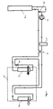
- Figure 1 is a schematic diagram of the refrigeration circuit of an air conditioning system according to an embodiment of the present invention for cooling the passenger compartment of a vehicle;
- Figure 2 is a schematic diagram of the air conditioning system of Fig 1 wherein the refrigeration circuit adapted to operate in a heat pump mode for heating the passenger compartment of a vehicle.
- Fig. 1 illustrates an air conditioning system according to the present invention for use with a vehicle to control the air temperature within the passenger compartment of the vehicle. The air conditioning system comprises a
compressor 10, a front heat exchanger 20 (condenser/gas cooler), which may be located in a front of the vehicle engine compartment, for utilising ambient air to cool/condense refrigerant, afirst heat exchanger 30, preferably provided in the front of the vehicle passenger compartment 25 (e.g. within the vehicle instrument panel or dashboard) capable of receiving ambient air from outside of the vehicle and arranged to discharge the air downstream of thefirst heat exchanger 30 into thepassenger compartment 25 of the vehicle, afurther heat exchanger 40, preferably in the rear of thepassenger compartment 25, arranged to receive air from thepassenger compartment 25 of the vehicle and to discharge air out of thepassenger compartment 25 downstream of thefurther heat exchanger 40, anexpansion valve 50 for reducing the pressure of the refrigerant and a refrigerant accumulator/reservoir 60. - As shown in Fig 1, when the air conditioning system is configured to cool the vehicle, the refrigerant circuit passes refrigerant from the
compressor 10 into thefront heat exchanger 20, wherein the refrigerant is condensed and/or cooled by heat transfer with ambient air passing through thefront heat exchanger 20, the refrigerant subsequently being passed into thefurther heat exchanger 40, wherein the refrigerant is further cooled by heat transfer with air from within thepassenger compartment 25 of the vehicle, said air having been cooled to below the temperature of the ambient air outside of the vehicle by virtue of the air conditioning system. The refrigerant is then passed through theexpansion valve 50, wherein the pressure of the refrigerant is reduced, before passing through thefirst heat exchanger 30 wherein the refrigerant is evaporated, thereby cooling air passing into thepassenger compartment 25 through thefirst heat exchanger 30. The refrigerant then exits thefirst heat exchanger 30 and passes through theaccumulator 50 before returning to thecompressor 10 to be compressed and passed back into the high pressure side of the refrigerant circuit. The air passing through the first heat exchanger can be selected from ambient air, recirculated passenger compartment air or a mixture of the two, depending upon the setting of the air conditioning control system, as is conventional in the art. - By using air drawn from the passenger compartment of the vehicle at a temperature lower than the ambient air outside of the vehicle to further cool the refrigerant as it passes through the further heat exchanger, the refrigerant can be cooled to a temperature below that achievable using ambient air alone without the detrimental effects of using the low pressure coolant to cool the high pressure coolant in an internal heat exchanger. Thus the present invention provides an increased coefficient of performance (COP) and reduced compressor outlet temperatures.
- By controlling the air flow through the further heat exchanged 40, the heat transfer between the air and the refrigerant and thus the amount of subcooling of the refrigerant can be controlled, thus controlling operation of the refrigeration system. This control of the airflow can be achieved by means of a variable speed blower or fan or by means of louvres or shutters over the further heat exchanger.
- As shown in Fig 2, the further heat exchanger can optionally be utilised in a heat pump refrigerant cycle wherein the
further heat exchanger 40 acts as a condenser/gas cooler for the refrigeration cycle in place of thefront heat exchanger 20. When used as a heat pump, the air temperature inside the passenger compartment is higher than the ambient temperature. By using thefurther heat exchanger 40 as a condenser/gas cooler in place of the front heat exchanger to cool the gas, saidfurther heat exchanger 40 receiving air at a higher temperature than that of the ambient air, the problem of ice formation in the condenser/gas cooler is avoided. - Whilst the preferred embodiment of the present invention has been described in relation to an air conditioning system for an automotive vehicle, it is envisaged that the present invention is equally applicable to any circumstances wherein the air temperature within a closed space is to be controlled, such as in a hotel room or other domestic dwelling or in other forms of transport, such as aircraft of boats.
Claims (8)
- A refrigeration system for an air conditioner comprising a compressor for compressing a refrigerant, a gas cooler or condenser downstream of the compressor utilising ambient air for cooling and/or condensing the refrigerant, at least one expansion valve downstream of the gas cooler/condenser for reducing the pressure of the refrigerant and a first heat exchanger downstream of the expansion valve for evaporating the refrigerant and for cooling air supplied to a space to be cooled, characterised by the provision of a further heat exchanger downstream of the gas cooler/condenser and upstream of the expansion valve, said further heat exchanger being arranged to receive air from the space to be cooled, such air being discharged from the space to be cooled downstream of the further heat exchanger.
- A refrigeration system as claimed in claim 1, wherein the refrigerant is carbon dioxide.
- A refrigeration system as claimed in any preceding claim, wherein the space to be cooled is the passenger compartment of a vehicle.
- A refrigeration system as claimed in claim 3, wherein the gas cooler/condenser is provided outside of the passenger compartment, preferably in the front of the vehicle.
- A refrigeration system as claimed in claim 3 or claim 4, wherein the further heat exchanger is provided in or adjacent a rear section of the passenger compartment.
- A refrigeration system as claimed in any preceding claim, further comprising control means for selectively adapting the system to operate as a heat pump whereby the refrigerant upstream of the compressor bypasses the condenser gas/cooler and passes directly into the first heat exchanger wherein the refrigerant is condensed/cooled, causing ambient air passing into the passenger compartment through the first heat exchanger to be heated, the refrigerant subsequently passing through the at least one expansion valve and then passing into the further heat exchanger wherein the refrigerant is evaporated by heat transfer with air from within the passenger compartment, the refrigerant passing from the further heat exchanger back to the compressor.
- A refrigeration system as claimed in any preceding claim, further comprising means for controlling the flow of air through the further heat exchanger.
- A refrigeration system as claimed in claim 7, wherein the means for controlling the flow of air through the further heat exchanger comprises a variable speed fan or blower.
Priority Applications (3)
| Application Number | Priority Date | Filing Date | Title |
|---|---|---|---|
| AT05253390T ATE367942T1 (en) | 2005-06-02 | 2005-06-02 | COOLING SYSTEM FOR AN AIR CONDITIONER |
| DE602005001771T DE602005001771T2 (en) | 2005-06-02 | 2005-06-02 | Cooling system for an air conditioner |
| EP05253390A EP1728662B1 (en) | 2005-06-02 | 2005-06-02 | Refrigeration system for an air conditioner |
Applications Claiming Priority (1)
| Application Number | Priority Date | Filing Date | Title |
|---|---|---|---|
| EP05253390A EP1728662B1 (en) | 2005-06-02 | 2005-06-02 | Refrigeration system for an air conditioner |
Publications (2)
| Publication Number | Publication Date |
|---|---|
| EP1728662A1 true EP1728662A1 (en) | 2006-12-06 |
| EP1728662B1 EP1728662B1 (en) | 2007-07-25 |
Family
ID=34941545
Family Applications (1)
| Application Number | Title | Priority Date | Filing Date |
|---|---|---|---|
| EP05253390A Expired - Lifetime EP1728662B1 (en) | 2005-06-02 | 2005-06-02 | Refrigeration system for an air conditioner |
Country Status (3)
| Country | Link |
|---|---|
| EP (1) | EP1728662B1 (en) |
| AT (1) | ATE367942T1 (en) |
| DE (1) | DE602005001771T2 (en) |
Cited By (3)
| Publication number | Priority date | Publication date | Assignee | Title |
|---|---|---|---|---|
| WO2015055427A1 (en) * | 2013-10-14 | 2015-04-23 | Weidmann Plastics Technology Ag | Motor vehicle having an air-conditioning system |
| CN113015639A (en) * | 2018-11-27 | 2021-06-22 | 三电汽车空调系统株式会社 | Air conditioner for vehicle |
| WO2022231819A1 (en) * | 2021-04-28 | 2022-11-03 | Apple Inc. | Thermal control system |
Citations (3)
| Publication number | Priority date | Publication date | Assignee | Title |
|---|---|---|---|---|
| DE10140630A1 (en) * | 2001-08-18 | 2003-02-27 | Bayerische Motoren Werke Ag | Cooling plant for motor vehicles has coolant expansion elements and heat accumulator with two operating modes |
| WO2003026103A1 (en) * | 2001-09-12 | 2003-03-27 | Zexel Valeo Climate Control Corporation | Power generator and vehicle air conditioner |
| EP1422085A1 (en) * | 2002-11-19 | 2004-05-26 | Delphi Technologies, Inc. | Dual evaporator air conditioning system and method of use |
-
2005
- 2005-06-02 AT AT05253390T patent/ATE367942T1/en not_active IP Right Cessation
- 2005-06-02 EP EP05253390A patent/EP1728662B1/en not_active Expired - Lifetime
- 2005-06-02 DE DE602005001771T patent/DE602005001771T2/en not_active Expired - Lifetime
Patent Citations (3)
| Publication number | Priority date | Publication date | Assignee | Title |
|---|---|---|---|---|
| DE10140630A1 (en) * | 2001-08-18 | 2003-02-27 | Bayerische Motoren Werke Ag | Cooling plant for motor vehicles has coolant expansion elements and heat accumulator with two operating modes |
| WO2003026103A1 (en) * | 2001-09-12 | 2003-03-27 | Zexel Valeo Climate Control Corporation | Power generator and vehicle air conditioner |
| EP1422085A1 (en) * | 2002-11-19 | 2004-05-26 | Delphi Technologies, Inc. | Dual evaporator air conditioning system and method of use |
Cited By (5)
| Publication number | Priority date | Publication date | Assignee | Title |
|---|---|---|---|---|
| WO2015055427A1 (en) * | 2013-10-14 | 2015-04-23 | Weidmann Plastics Technology Ag | Motor vehicle having an air-conditioning system |
| CN105722702A (en) * | 2013-10-14 | 2016-06-29 | 魏德塑料有限责任公司 | Motor vehicle having air-conditioning system |
| CN105722702B (en) * | 2013-10-14 | 2018-12-25 | 魏德塑料有限责任公司 | Has air-conditioned motor vehicle |
| CN113015639A (en) * | 2018-11-27 | 2021-06-22 | 三电汽车空调系统株式会社 | Air conditioner for vehicle |
| WO2022231819A1 (en) * | 2021-04-28 | 2022-11-03 | Apple Inc. | Thermal control system |
Also Published As
| Publication number | Publication date |
|---|---|
| DE602005001771T2 (en) | 2008-04-10 |
| ATE367942T1 (en) | 2007-08-15 |
| EP1728662B1 (en) | 2007-07-25 |
| DE602005001771D1 (en) | 2007-09-06 |
Similar Documents
| Publication | Publication Date | Title |
|---|---|---|
| CN107428222B (en) | Vehicle heat pump system | |
| EP3081408B1 (en) | Automotive heat pump system | |
| US10744854B2 (en) | Air conditioning system for vehicle and method for controlling same | |
| US20190241044A1 (en) | Heat pump cycle apparatus | |
| CN109515115B (en) | Automobile air conditioning system using carbon dioxide as working medium and control method | |
| CN104515335A (en) | Heat pump system for vehicle | |
| US10710433B2 (en) | AC-system with very high cooling capacity | |
| JP2014228190A (en) | Refrigeration cycle device | |
| CN109477668B (en) | Refrigeration cycle device | |
| CN106414127A (en) | Automotive air conditioning system | |
| JP4415835B2 (en) | Refrigeration cycle equipment for vehicles | |
| JP2013203221A (en) | Air conditioner for vehicle | |
| CN109869941B (en) | Heat pump system, air suction superheat degree and vapor-liquid separator accumulated liquid evaporation control method | |
| CN106440429B (en) | Dynamically controlled vehicle cooling and heating system operable in a multi-stage compression cycle | |
| CN110475683B (en) | Air conditioning apparatus | |
| CN111433538B (en) | Refrigeration cycle device | |
| US12365219B2 (en) | Refrigeration cycle device | |
| JP6537928B2 (en) | Heat exchanger and heat pump system | |
| JP6733625B2 (en) | Refrigeration cycle equipment | |
| EP1728662B1 (en) | Refrigeration system for an air conditioner | |
| JP6544287B2 (en) | Air conditioner | |
| JP2015116934A (en) | Heat pump cycle device. | |
| EP1728657B1 (en) | Air conditioning system | |
| CN108027178B (en) | heat pump | |
| JP4400533B2 (en) | Ejector refrigeration cycle |
Legal Events
| Date | Code | Title | Description |
|---|---|---|---|
| PUAI | Public reference made under article 153(3) epc to a published international application that has entered the european phase |
Free format text: ORIGINAL CODE: 0009012 |
|
| 17P | Request for examination filed |
Effective date: 20050907 |
|
| AK | Designated contracting states |
Kind code of ref document: A1 Designated state(s): AT BE BG CH CY CZ DE DK EE ES FI FR GB GR HU IE IS IT LI LT LU MC NL PL PT RO SE SI SK TR |
|
| AX | Request for extension of the european patent |
Extension state: AL BA HR LV MK YU |
|
| GRAP | Despatch of communication of intention to grant a patent |
Free format text: ORIGINAL CODE: EPIDOSNIGR1 |
|
| RIN1 | Information on inventor provided before grant (corrected) |
Inventor name: PETESCH, JEAN-CLAUDE |
|
| GRAS | Grant fee paid |
Free format text: ORIGINAL CODE: EPIDOSNIGR3 |
|
| GRAA | (expected) grant |
Free format text: ORIGINAL CODE: 0009210 |
|
| AK | Designated contracting states |
Kind code of ref document: B1 Designated state(s): AT BE BG CH CY CZ DE DK EE ES FI FR GB GR HU IE IS IT LI LT LU MC NL PL PT RO SE SI SK TR |
|
| REG | Reference to a national code |
Ref country code: GB Ref legal event code: FG4D |
|
| AKX | Designation fees paid |
Designated state(s): AT BE BG CH CY CZ DE DK EE ES FI FR GB GR HU IE IS IT LI LT LU MC NL PL PT RO SE SI SK TR |
|
| REG | Reference to a national code |
Ref country code: CH Ref legal event code: EP |
|
| REG | Reference to a national code |
Ref country code: IE Ref legal event code: FG4D |
|
| REF | Corresponds to: |
Ref document number: 602005001771 Country of ref document: DE Date of ref document: 20070906 Kind code of ref document: P |
|
| ET | Fr: translation filed | ||
| PG25 | Lapsed in a contracting state [announced via postgrant information from national office to epo] |
Ref country code: NL Free format text: LAPSE BECAUSE OF FAILURE TO SUBMIT A TRANSLATION OF THE DESCRIPTION OR TO PAY THE FEE WITHIN THE PRESCRIBED TIME-LIMIT Effective date: 20070725 Ref country code: PT Free format text: LAPSE BECAUSE OF FAILURE TO SUBMIT A TRANSLATION OF THE DESCRIPTION OR TO PAY THE FEE WITHIN THE PRESCRIBED TIME-LIMIT Effective date: 20071226 Ref country code: IS Free format text: LAPSE BECAUSE OF FAILURE TO SUBMIT A TRANSLATION OF THE DESCRIPTION OR TO PAY THE FEE WITHIN THE PRESCRIBED TIME-LIMIT Effective date: 20071125 Ref country code: FI Free format text: LAPSE BECAUSE OF FAILURE TO SUBMIT A TRANSLATION OF THE DESCRIPTION OR TO PAY THE FEE WITHIN THE PRESCRIBED TIME-LIMIT Effective date: 20070725 Ref country code: BG Free format text: LAPSE BECAUSE OF FAILURE TO SUBMIT A TRANSLATION OF THE DESCRIPTION OR TO PAY THE FEE WITHIN THE PRESCRIBED TIME-LIMIT Effective date: 20071025 Ref country code: ES Free format text: LAPSE BECAUSE OF FAILURE TO SUBMIT A TRANSLATION OF THE DESCRIPTION OR TO PAY THE FEE WITHIN THE PRESCRIBED TIME-LIMIT Effective date: 20071105 Ref country code: LT Free format text: LAPSE BECAUSE OF FAILURE TO SUBMIT A TRANSLATION OF THE DESCRIPTION OR TO PAY THE FEE WITHIN THE PRESCRIBED TIME-LIMIT Effective date: 20070725 |
|
| REG | Reference to a national code |
Ref country code: CH Ref legal event code: PL |
|
| NLV1 | Nl: lapsed or annulled due to failure to fulfill the requirements of art. 29p and 29m of the patents act | ||
| PG25 | Lapsed in a contracting state [announced via postgrant information from national office to epo] |
Ref country code: PL Free format text: LAPSE BECAUSE OF FAILURE TO SUBMIT A TRANSLATION OF THE DESCRIPTION OR TO PAY THE FEE WITHIN THE PRESCRIBED TIME-LIMIT Effective date: 20070725 Ref country code: AT Free format text: LAPSE BECAUSE OF FAILURE TO SUBMIT A TRANSLATION OF THE DESCRIPTION OR TO PAY THE FEE WITHIN THE PRESCRIBED TIME-LIMIT Effective date: 20070725 Ref country code: LI Free format text: LAPSE BECAUSE OF FAILURE TO SUBMIT A TRANSLATION OF THE DESCRIPTION OR TO PAY THE FEE WITHIN THE PRESCRIBED TIME-LIMIT Effective date: 20070725 Ref country code: CH Free format text: LAPSE BECAUSE OF FAILURE TO SUBMIT A TRANSLATION OF THE DESCRIPTION OR TO PAY THE FEE WITHIN THE PRESCRIBED TIME-LIMIT Effective date: 20070725 |
|
| PG25 | Lapsed in a contracting state [announced via postgrant information from national office to epo] |
Ref country code: BE Free format text: LAPSE BECAUSE OF FAILURE TO SUBMIT A TRANSLATION OF THE DESCRIPTION OR TO PAY THE FEE WITHIN THE PRESCRIBED TIME-LIMIT Effective date: 20070725 |
|
| PG25 | Lapsed in a contracting state [announced via postgrant information from national office to epo] |
Ref country code: GR Free format text: LAPSE BECAUSE OF FAILURE TO SUBMIT A TRANSLATION OF THE DESCRIPTION OR TO PAY THE FEE WITHIN THE PRESCRIBED TIME-LIMIT Effective date: 20071026 Ref country code: DK Free format text: LAPSE BECAUSE OF FAILURE TO SUBMIT A TRANSLATION OF THE DESCRIPTION OR TO PAY THE FEE WITHIN THE PRESCRIBED TIME-LIMIT Effective date: 20070725 |
|
| PG25 | Lapsed in a contracting state [announced via postgrant information from national office to epo] |
Ref country code: SK Free format text: LAPSE BECAUSE OF FAILURE TO SUBMIT A TRANSLATION OF THE DESCRIPTION OR TO PAY THE FEE WITHIN THE PRESCRIBED TIME-LIMIT Effective date: 20070725 Ref country code: CZ Free format text: LAPSE BECAUSE OF FAILURE TO SUBMIT A TRANSLATION OF THE DESCRIPTION OR TO PAY THE FEE WITHIN THE PRESCRIBED TIME-LIMIT Effective date: 20070725 |
|
| PLBE | No opposition filed within time limit |
Free format text: ORIGINAL CODE: 0009261 |
|
| STAA | Information on the status of an ep patent application or granted ep patent |
Free format text: STATUS: NO OPPOSITION FILED WITHIN TIME LIMIT |
|
| PG25 | Lapsed in a contracting state [announced via postgrant information from national office to epo] |
Ref country code: RO Free format text: LAPSE BECAUSE OF FAILURE TO SUBMIT A TRANSLATION OF THE DESCRIPTION OR TO PAY THE FEE WITHIN THE PRESCRIBED TIME-LIMIT Effective date: 20070725 Ref country code: SE Free format text: LAPSE BECAUSE OF FAILURE TO SUBMIT A TRANSLATION OF THE DESCRIPTION OR TO PAY THE FEE WITHIN THE PRESCRIBED TIME-LIMIT Effective date: 20071025 |
|
| 26N | No opposition filed |
Effective date: 20080428 |
|
| PG25 | Lapsed in a contracting state [announced via postgrant information from national office to epo] |
Ref country code: MC Free format text: LAPSE BECAUSE OF NON-PAYMENT OF DUE FEES Effective date: 20080630 |
|
| PG25 | Lapsed in a contracting state [announced via postgrant information from national office to epo] |
Ref country code: IE Free format text: LAPSE BECAUSE OF NON-PAYMENT OF DUE FEES Effective date: 20080602 Ref country code: EE Free format text: LAPSE BECAUSE OF FAILURE TO SUBMIT A TRANSLATION OF THE DESCRIPTION OR TO PAY THE FEE WITHIN THE PRESCRIBED TIME-LIMIT Effective date: 20070725 |
|
| PG25 | Lapsed in a contracting state [announced via postgrant information from national office to epo] |
Ref country code: SI Free format text: LAPSE BECAUSE OF FAILURE TO SUBMIT A TRANSLATION OF THE DESCRIPTION OR TO PAY THE FEE WITHIN THE PRESCRIBED TIME-LIMIT Effective date: 20070725 |
|
| PG25 | Lapsed in a contracting state [announced via postgrant information from national office to epo] |
Ref country code: CY Free format text: LAPSE BECAUSE OF FAILURE TO SUBMIT A TRANSLATION OF THE DESCRIPTION OR TO PAY THE FEE WITHIN THE PRESCRIBED TIME-LIMIT Effective date: 20070725 |
|
| GBPC | Gb: european patent ceased through non-payment of renewal fee |
Effective date: 20090602 |
|
| PG25 | Lapsed in a contracting state [announced via postgrant information from national office to epo] |
Ref country code: GB Free format text: LAPSE BECAUSE OF NON-PAYMENT OF DUE FEES Effective date: 20090602 |
|
| PG25 | Lapsed in a contracting state [announced via postgrant information from national office to epo] |
Ref country code: HU Free format text: LAPSE BECAUSE OF FAILURE TO SUBMIT A TRANSLATION OF THE DESCRIPTION OR TO PAY THE FEE WITHIN THE PRESCRIBED TIME-LIMIT Effective date: 20080126 Ref country code: LU Free format text: LAPSE BECAUSE OF NON-PAYMENT OF DUE FEES Effective date: 20080602 |
|
| PG25 | Lapsed in a contracting state [announced via postgrant information from national office to epo] |
Ref country code: TR Free format text: LAPSE BECAUSE OF FAILURE TO SUBMIT A TRANSLATION OF THE DESCRIPTION OR TO PAY THE FEE WITHIN THE PRESCRIBED TIME-LIMIT Effective date: 20070725 |
|
| REG | Reference to a national code |
Ref country code: DE Ref legal event code: R082 Ref document number: 602005001771 Country of ref document: DE Representative=s name: BRP RENAUD UND PARTNER MBB RECHTSANWAELTE PATE, DE Ref country code: DE Ref legal event code: R082 Ref document number: 602005001771 Country of ref document: DE Representative=s name: BRP RENAUD UND PARTNER MBB, DE Ref country code: DE Ref legal event code: R081 Ref document number: 602005001771 Country of ref document: DE Owner name: MAHLE INTERNATIONAL GMBH, DE Free format text: FORMER OWNER: DELPHI TECHNOLOGIES, INC., TROY, MICH., US |
|
| REG | Reference to a national code |
Ref country code: FR Ref legal event code: PLFP Year of fee payment: 12 |
|
| REG | Reference to a national code |
Ref country code: FR Ref legal event code: PLFP Year of fee payment: 13 |
|
| REG | Reference to a national code |
Ref country code: FR Ref legal event code: TP Owner name: MAHLE INTERNATIONAL GMBH, DE Effective date: 20180103 |
|
| REG | Reference to a national code |
Ref country code: FR Ref legal event code: PLFP Year of fee payment: 14 |
|
| PGFP | Annual fee paid to national office [announced via postgrant information from national office to epo] |
Ref country code: FR Payment date: 20200626 Year of fee payment: 16 |
|
| PGFP | Annual fee paid to national office [announced via postgrant information from national office to epo] |
Ref country code: IT Payment date: 20200618 Year of fee payment: 16 |
|
| PGFP | Annual fee paid to national office [announced via postgrant information from national office to epo] |
Ref country code: DE Payment date: 20200827 Year of fee payment: 16 |
|
| REG | Reference to a national code |
Ref country code: DE Ref legal event code: R119 Ref document number: 602005001771 Country of ref document: DE |
|
| PG25 | Lapsed in a contracting state [announced via postgrant information from national office to epo] |
Ref country code: DE Free format text: LAPSE BECAUSE OF NON-PAYMENT OF DUE FEES Effective date: 20220101 |
|
| PG25 | Lapsed in a contracting state [announced via postgrant information from national office to epo] |
Ref country code: FR Free format text: LAPSE BECAUSE OF NON-PAYMENT OF DUE FEES Effective date: 20210630 |
|
| PG25 | Lapsed in a contracting state [announced via postgrant information from national office to epo] |
Ref country code: IT Free format text: LAPSE BECAUSE OF NON-PAYMENT OF DUE FEES Effective date: 20210602 |