EP1728581A1 - Laser working machine with a Laser working nozzle adjustment means for aligning the laser beam with the hole of the laser working nozzle - Google Patents
Laser working machine with a Laser working nozzle adjustment means for aligning the laser beam with the hole of the laser working nozzle Download PDFInfo
- Publication number
- EP1728581A1 EP1728581A1 EP05011709A EP05011709A EP1728581A1 EP 1728581 A1 EP1728581 A1 EP 1728581A1 EP 05011709 A EP05011709 A EP 05011709A EP 05011709 A EP05011709 A EP 05011709A EP 1728581 A1 EP1728581 A1 EP 1728581A1
- Authority
- EP
- European Patent Office
- Prior art keywords
- laser
- laser processing
- nozzle
- mirror
- processing machine
- Prior art date
- Legal status (The legal status is an assumption and is not a legal conclusion. Google has not performed a legal analysis and makes no representation as to the accuracy of the status listed.)
- Granted
Links
Images


Classifications
-
- B—PERFORMING OPERATIONS; TRANSPORTING
- B23—MACHINE TOOLS; METAL-WORKING NOT OTHERWISE PROVIDED FOR
- B23K—SOLDERING OR UNSOLDERING; WELDING; CLADDING OR PLATING BY SOLDERING OR WELDING; CUTTING BY APPLYING HEAT LOCALLY, e.g. FLAME CUTTING; WORKING BY LASER BEAM
- B23K26/00—Working by laser beam, e.g. welding, cutting or boring
- B23K26/08—Devices involving relative movement between laser beam and workpiece
- B23K26/0869—Devices involving movement of the laser head in at least one axial direction
- B23K26/0876—Devices involving movement of the laser head in at least one axial direction in at least two axial directions
-
- B—PERFORMING OPERATIONS; TRANSPORTING
- B23—MACHINE TOOLS; METAL-WORKING NOT OTHERWISE PROVIDED FOR
- B23K—SOLDERING OR UNSOLDERING; WELDING; CLADDING OR PLATING BY SOLDERING OR WELDING; CUTTING BY APPLYING HEAT LOCALLY, e.g. FLAME CUTTING; WORKING BY LASER BEAM
- B23K26/00—Working by laser beam, e.g. welding, cutting or boring
- B23K26/02—Positioning or observing the workpiece, e.g. with respect to the point of impact; Aligning, aiming or focusing the laser beam
- B23K26/03—Observing, e.g. monitoring, the workpiece
- B23K26/032—Observing, e.g. monitoring, the workpiece using optical means
-
- B—PERFORMING OPERATIONS; TRANSPORTING
- B23—MACHINE TOOLS; METAL-WORKING NOT OTHERWISE PROVIDED FOR
- B23K—SOLDERING OR UNSOLDERING; WELDING; CLADDING OR PLATING BY SOLDERING OR WELDING; CUTTING BY APPLYING HEAT LOCALLY, e.g. FLAME CUTTING; WORKING BY LASER BEAM
- B23K26/00—Working by laser beam, e.g. welding, cutting or boring
- B23K26/02—Positioning or observing the workpiece, e.g. with respect to the point of impact; Aligning, aiming or focusing the laser beam
- B23K26/04—Automatically aligning, aiming or focusing the laser beam, e.g. using the back-scattered light
- B23K26/042—Automatically aligning the laser beam
- B23K26/043—Automatically aligning the laser beam along the beam path, i.e. alignment of laser beam axis relative to laser beam apparatus
-
- B—PERFORMING OPERATIONS; TRANSPORTING
- B23—MACHINE TOOLS; METAL-WORKING NOT OTHERWISE PROVIDED FOR
- B23K—SOLDERING OR UNSOLDERING; WELDING; CLADDING OR PLATING BY SOLDERING OR WELDING; CUTTING BY APPLYING HEAT LOCALLY, e.g. FLAME CUTTING; WORKING BY LASER BEAM
- B23K26/00—Working by laser beam, e.g. welding, cutting or boring
- B23K26/02—Positioning or observing the workpiece, e.g. with respect to the point of impact; Aligning, aiming or focusing the laser beam
- B23K26/06—Shaping the laser beam, e.g. by masks or multi-focusing
- B23K26/064—Shaping the laser beam, e.g. by masks or multi-focusing by means of optical elements, e.g. lenses, mirrors or prisms
- B23K26/0643—Shaping the laser beam, e.g. by masks or multi-focusing by means of optical elements, e.g. lenses, mirrors or prisms comprising mirrors
-
- B—PERFORMING OPERATIONS; TRANSPORTING
- B23—MACHINE TOOLS; METAL-WORKING NOT OTHERWISE PROVIDED FOR
- B23K—SOLDERING OR UNSOLDERING; WELDING; CLADDING OR PLATING BY SOLDERING OR WELDING; CUTTING BY APPLYING HEAT LOCALLY, e.g. FLAME CUTTING; WORKING BY LASER BEAM
- B23K26/00—Working by laser beam, e.g. welding, cutting or boring
- B23K26/02—Positioning or observing the workpiece, e.g. with respect to the point of impact; Aligning, aiming or focusing the laser beam
- B23K26/06—Shaping the laser beam, e.g. by masks or multi-focusing
- B23K26/064—Shaping the laser beam, e.g. by masks or multi-focusing by means of optical elements, e.g. lenses, mirrors or prisms
- B23K26/0648—Shaping the laser beam, e.g. by masks or multi-focusing by means of optical elements, e.g. lenses, mirrors or prisms comprising lenses
-
- B—PERFORMING OPERATIONS; TRANSPORTING
- B23—MACHINE TOOLS; METAL-WORKING NOT OTHERWISE PROVIDED FOR
- B23K—SOLDERING OR UNSOLDERING; WELDING; CLADDING OR PLATING BY SOLDERING OR WELDING; CUTTING BY APPLYING HEAT LOCALLY, e.g. FLAME CUTTING; WORKING BY LASER BEAM
- B23K26/00—Working by laser beam, e.g. welding, cutting or boring
- B23K26/02—Positioning or observing the workpiece, e.g. with respect to the point of impact; Aligning, aiming or focusing the laser beam
- B23K26/06—Shaping the laser beam, e.g. by masks or multi-focusing
- B23K26/0665—Shaping the laser beam, e.g. by masks or multi-focusing by beam condensation on the workpiece, e.g. for focusing
-
- B—PERFORMING OPERATIONS; TRANSPORTING
- B23—MACHINE TOOLS; METAL-WORKING NOT OTHERWISE PROVIDED FOR
- B23K—SOLDERING OR UNSOLDERING; WELDING; CLADDING OR PLATING BY SOLDERING OR WELDING; CUTTING BY APPLYING HEAT LOCALLY, e.g. FLAME CUTTING; WORKING BY LASER BEAM
- B23K26/00—Working by laser beam, e.g. welding, cutting or boring
- B23K26/08—Devices involving relative movement between laser beam and workpiece
- B23K26/10—Devices involving relative movement between laser beam and workpiece using a fixed support, i.e. involving moving the laser beam
-
- B—PERFORMING OPERATIONS; TRANSPORTING
- B23—MACHINE TOOLS; METAL-WORKING NOT OTHERWISE PROVIDED FOR
- B23K—SOLDERING OR UNSOLDERING; WELDING; CLADDING OR PLATING BY SOLDERING OR WELDING; CUTTING BY APPLYING HEAT LOCALLY, e.g. FLAME CUTTING; WORKING BY LASER BEAM
- B23K26/00—Working by laser beam, e.g. welding, cutting or boring
- B23K26/14—Working by laser beam, e.g. welding, cutting or boring using a fluid stream, e.g. a jet of gas, in conjunction with the laser beam; Nozzles therefor
- B23K26/142—Working by laser beam, e.g. welding, cutting or boring using a fluid stream, e.g. a jet of gas, in conjunction with the laser beam; Nozzles therefor for the removal of by-products
-
- B—PERFORMING OPERATIONS; TRANSPORTING
- B23—MACHINE TOOLS; METAL-WORKING NOT OTHERWISE PROVIDED FOR
- B23K—SOLDERING OR UNSOLDERING; WELDING; CLADDING OR PLATING BY SOLDERING OR WELDING; CUTTING BY APPLYING HEAT LOCALLY, e.g. FLAME CUTTING; WORKING BY LASER BEAM
- B23K26/00—Working by laser beam, e.g. welding, cutting or boring
- B23K26/14—Working by laser beam, e.g. welding, cutting or boring using a fluid stream, e.g. a jet of gas, in conjunction with the laser beam; Nozzles therefor
- B23K26/1462—Nozzles; Features related to nozzles
- B23K26/1494—Maintenance of nozzles
-
- B—PERFORMING OPERATIONS; TRANSPORTING
- B23—MACHINE TOOLS; METAL-WORKING NOT OTHERWISE PROVIDED FOR
- B23K—SOLDERING OR UNSOLDERING; WELDING; CLADDING OR PLATING BY SOLDERING OR WELDING; CUTTING BY APPLYING HEAT LOCALLY, e.g. FLAME CUTTING; WORKING BY LASER BEAM
- B23K26/00—Working by laser beam, e.g. welding, cutting or boring
- B23K26/70—Auxiliary operations or equipment
- B23K26/702—Auxiliary equipment
- B23K26/705—Beam measuring device
Definitions
- the present invention relates to a laser processing machine with an optical system for beam guidance and focusing of a laser processing beam.
- the Applicant has set itself the task of being able to automate the most centric arrangement of the laser processing beam within the nozzle bore of a laser processing nozzle of the laser cutting head.
- a laser processing machine with an optical system for beam guidance and focusing of a laser beam which comprises means for illuminating the nozzle bore of a laser processing nozzle of the laser processing head, means for determining the center of the nozzle bore by means of illumination and means for determining the distance of the laser beam focus to the nozzle center.
- the center of the nozzle can be determined by a reference measurement, with one image each of the illuminated nozzle and a focused beam being recorded and evaluated.
- the measurement signals can be used via the machine control for automatic laser nozzle centering.
- the trained for laser machining laser beam may be provided for illuminating the nozzle bore.
- the existing laser beam is defocused and used for illumination.
- a separate light source is a laser diode for beam generation, an optical system for beam expansion, a deflection mirror and a mirror for reflecting the light beam collinear to the laser processing beam into consideration.
- the invention can be used with a per se known process light measuring device combined and advantageously integrated into a laser processing machine.
- an image acquisition and image evaluation device is advantageous.
- the optics for beam guidance and focusing of a laser beam may include an adaptive mirror that can be used to adjust the illumination.
- FIG. 1 shows the structure of a laser processing machine 1 for laser cutting with a CO 2 laser 2, a laser processing head 3 and a workpiece support 4 .
- a generated laser beam 5 is guided by means of deflecting mirrors to the laser processing head 3 and directed by means of mirrors on a workpiece 6 .
- the device according to the invention can be installed at any point.
- the laser beam 5 Before a continuous kerf is formed, the laser beam 5 must penetrate the workpiece 6. The sheet 6 must be spot-melted or oxidized at one point, and the melt must be blown out.
- laser power can be gradually increased, reduced, and held constant for a period of time until the piercing hole is created.
- Both piercing and laser cutting are assisted by the addition of a gas.
- cutting gases 7 oxygen, nitrogen, compressed air and / or application-specific gases can be used. Which gas is ultimately used depends on which materials are cut and what quality requirements are placed on the workpiece.
- the material is melted and oxidized for the most part.
- the resulting melt is blown out together with the iron oxides.
- Resulting particles and gases can be sucked out of a suction chamber 9 by means of a suction device 8 .
- the device for illuminating a cutting nozzle bore 10 of a cutting nozzle 10 'of the cutting head 3 essentially comprises a laser diode 11, a deflection mirror 12 arranged at an angle of 45 ° and a mirror 13 which allows a visible laser beam 14 collinear to the laser cutting beam 5 of the CO 2 laser undvantn.
- the laser beam 14 of the laser diode 11 is widened so that it strikes the edge of the mirror 13.
- the focal length of an expander lens 15 and its distance to the mirror 13 are chosen so that a focusing optics 16 (lens or mirror) is fully illuminated by means of the laser beam 14 of the laser diode 11.
- the focus position of lens or focusing mirror 16 is now adjusted so far that the nozzle bore 10 is fully illuminated.
- the laser beam 14 thereby brushes the edge of the nozzle bore 10.
- a directly below the laser cutting nozzle 10 'arranged focusing screen 18 shows a red spot with a diameter D, the boundary corresponds exactly to the nozzle bore 10.
- camera and image analysis can now in one first method step exactly the nozzle center of the nozzle bore 10 is determined and evaluated (see Figure 4 ).
- the focus position is placed in a second process step exactly in the plane of the nozzle lower edge.
- the spot corresponding to the focus has a diameter D ' of about 0.1 mm. Its center is determined again (see FIG. 5 ).
- the deviation from the center of the jet to the middle of the jet can be determined and used for automatic adjustment.
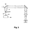
- FIG. 3 shows the combination of the invention with a process light measuring device.
- the most important point is that the mirror 13 'has a hole through which the processing laser beam 5 passes.
- the additional beam source is coupled via a partially transmissive mirror 12 ' and the so-called.
- Scraper mirror 13' in the beam guide As a mirror 13 'with the PCS scraper a suitable mirror in the laser cutting machine already exists, which can be additionally used for this purpose.
- the laser cutting machine may be provided with the optical process light measuring device, wherein the mirror 13 'part of the process light measuring device.
- the process light measuring device may be of conventional design. Such measuring devices are sold, for example, by the company TRUMPF, Ditzingen, Germany under the name "PCS".
- PCS is an optical system that measures the process light during the puncture.
- the plunge process can be controlled (gentle grooving) and / or the piercing end can be detected with the aid of these measured values (gentle and full grooving).
- Back-reflected process light 5 ' which arises due to the laser power beam at the puncture position, is directed by means of the scraper mirror 13' onto a photodiode 19 , which converts its intensity into a corresponding current.
- the electronics 20 in the measuring head measures this current and transmits these measured values digitally to the evaluation electronics, which process these data accordingly.
Abstract
Description
Die vorliegende Erfindung betrifft eine Laserbearbeitungsmaschine mit einer Optik zur Strahlführung und Fokussierung eines Laserbearbeitungsstrahls.The present invention relates to a laser processing machine with an optical system for beam guidance and focusing of a laser processing beam.
Derartige Laserbearbeitungsmaschinen sind allgemein bekannt.Such laser processing machines are well known.
Für eine optimale Materialbearbeitung ist es erforderlich, den Laserstrahl innerhalb der Laserbearbeitungsdüse möglichst zentrisch anzuordnen. Diese Laserbearbeitungsdüsenjustierüng wird bisher manuell durchgeführt.For optimal material processing, it is necessary to arrange the laser beam as centrally as possible within the laser processing nozzle. This laser machining nozzle adjustment has hitherto been carried out manually.
Der Anmelder hat sich die Aufgabe gestellt, die möglichst zentrische Anordnung des Laserbearbeitungsstrahls innerhalb der Düsenbohrung einer Laserbearbeitungsdüse des Laserschneidkopfs automatisieren zu können.The Applicant has set itself the task of being able to automate the most centric arrangement of the laser processing beam within the nozzle bore of a laser processing nozzle of the laser cutting head.
Diese Aufgabe wird gemäß Patentanspruch 1 durch eine Laserbearbeitungsmaschine mit einer Optik zur Strahlführung und Fokussierung eines Laserstrahls gelöst, welche eine Einrichtung zur Ausleuchtung der Düsenbohrung einer Laserbearbeitungsdüse des Laserbearbeitungskopfs, eine Einrichtung zur Bestimmung der Mitte der Düsenbohrung mithilfe der Ausleuchtung und eine Einrichtung zur Bestimmung des Abstandes des Laserstrahlfokus zur Düsenmitte umfasst.This object is achieved according to claim 1 by a laser processing machine with an optical system for beam guidance and focusing of a laser beam, which comprises means for illuminating the nozzle bore of a laser processing nozzle of the laser processing head, means for determining the center of the nozzle bore by means of illumination and means for determining the distance of the laser beam focus to the nozzle center.
Durch die Erfindung kann die Düsenmitte durch eine Referenzmessung bestimmt werden, wobei je ein Bild der ausgeleuchteten Düse und eines fokussierten Strahles aufgenommen und ausgewertet wird. Die Messsignale können über die Maschinensteuerung für die automatische Laserdüsenzentrierung verwendet werden.By means of the invention, the center of the nozzle can be determined by a reference measurement, with one image each of the illuminated nozzle and a focused beam being recorded and evaluated. The measurement signals can be used via the machine control for automatic laser nozzle centering.
Der zur Laserbearbeitung ausgebildete Laserstrahl kann zur Ausleuchtung der Düsenbohrung vorgesehen sein. Der vorhandene Laserstrahl wird defokussiert und zur Ausleuchtung herangezogen.The trained for laser machining laser beam may be provided for illuminating the nozzle bore. The existing laser beam is defocused and used for illumination.
Dies hat den Vorteil, dass keine zusätzliche Lichtquelle verwendet werden muss.This has the advantage that no additional light source has to be used.
Es kann aber auch eine separate Lichtquelle zur Ausleuchtung der Düsenbohrung vorgesehen sein. Dies hat den Vorteil, dass der zur Laserbearbeitung ausgebildete Laserstrahl nicht verstellt werden muss. Ein weiterer wesentlicher Vorteil bei der Verwendung einer separaten Lichtquelle liegt darin, dass man sichtbares Licht verwendet kann. Daher können Detektoren für sichtbares Licht eingesetzt werden, welche standardmäßig und kostengünstig hergestellt werden können.But it can also be provided a separate light source for illuminating the nozzle bore. This has the advantage that the laser beam formed for laser processing does not have to be adjusted. Another significant advantage of using a separate light source is that you can use visible light. Therefore, visible light detectors can be used which can be manufactured as standard and inexpensively.
In technischer Umsetzung der Arbeitsweise mit einer separaten Lichtquelle kommen eine Laserdiode zur Strahlerzeugung, eine Optik zur Strahlaufweitung, ein Umlenkspiegel und ein Spiegel zur Einspiegelung des Lichtstrahls kollinear zum Laserbearbeitungsstrahl in Betracht.In technical implementation of the operation with a separate light source is a laser diode for beam generation, an optical system for beam expansion, a deflection mirror and a mirror for reflecting the light beam collinear to the laser processing beam into consideration.
Wenn der Umlenkspiegel und der Spiegel Teil einer Prozesslichtmesseinrichtung sind, kann die Erfindung mit einer an sich bekannten Prozesslichtmesseinrichtung kombiniert und vorteilhaft in eine Laserbearbeitungsmaschine integriert werden.If the deflecting mirror and the mirror are part of a process light measuring device, the invention can be used with a per se known process light measuring device combined and advantageously integrated into a laser processing machine.
Zur Auswertung ist eine Bilderfassungs- und Bildauswerteeinrichtung vorteilhaft.For evaluation, an image acquisition and image evaluation device is advantageous.
Die Optik zur Strahlführung und Fokussierung eines Laserstrahls kann einen adaptiven Spiegel umfassen, der zur Einstellung der Ausleuchtung eingesetzt werden kann.The optics for beam guidance and focusing of a laser beam may include an adaptive mirror that can be used to adjust the illumination.
Bevorzugte Ausführungsbeispiele der Erfindung werden anhand der schematischen Zeichnung erläutert. Es zeigt:
- Figur 1
- eine Laserschneidmaschine;
Figur 2- einen Teil der Laserstrahlführung und eine Einspiegelung eines weiteren Laserstrahls zur Ausleuchtung der Schneiddüsenbohrung;
Figur 3- eine Variante der Einspiegelung in Verbindung mit einer Prozesslichtmessung;
Figur 4- den fokussierten Laserschneidstrahl innerhalb der Schneiddüse;
Figur 5- die Ausleuchtung der Schneiddüsenbohrung mithilfe des weiteren Laserstrahls;
Figur 6- eine Draufsicht eines Quadrantensektors.
- FIG. 1
- a laser cutting machine;
- FIG. 2
- a portion of the laser beam guide and a reflection of a further laser beam for illuminating the cutting nozzle bore;
- FIG. 3
- a variant of the reflection in conjunction with a process light measurement;
- FIG. 4
- the focused laser cutting beam within the cutting nozzle;
- FIG. 5
- the illumination of the cutting nozzle bore by means of the further laser beam;
- FIG. 6
- a top view of a quadrant sector.
Aus der Figur 1 ist der Aufbau einer Laserbearbeitungsmaschine 1 zum Laserschneiden mit einem CO2-Laser 2, einem Laserbearbeitungskopf 3 und einer Werkstückauflage 4 ersichtlich. Ein erzeugter Laserstrahl 5 wird mithilfe von Umlenkspiegeln zum Laserbearbeitungskopf 3 geführt und mithilfe von Spiegeln auf ein Werkstück 6 gerichtet. In die Strahlführung des Laserstrahls 5 kann die erfindungsgemäße Vorrichtung an beliebiger Stelle eingebaut werden. FIG. 1 shows the structure of a laser processing machine 1 for laser cutting with a CO 2 laser 2, a
Bevor eine durchgängige Schnittfuge entsteht, muss der Laserstrahl 5 das Werkstück 6 durchdringen. Das Blech 6 muss an einer Stelle punktförmig geschmolzen oder oxidiert werden, und die Schmelze muss ausgeblasen werden.Before a continuous kerf is formed, the
Beim langsamen Einstechen mit einer Rampe kann die Laserleistung allmählich erhöht, reduziert und über einen bestimmten Zeitraum konstant gehalten werden, bis das Einstechloch erzeugt ist. Sowohl das Einstechen als auch das Laserschneiden werden durch Hinzufügen eines Gases unterstützt. Als Schneidgase 7 können Sauerstoff, Stickstoff, Druckluft und/oder anwendungsspezifische Gase eingesetzt werden. Welches Gas letztendlich verwendet wird, ist davon abhängig, welche Materialien geschnitten und welche Qualitätsansprüche an das Werkstück gestellt werden.With slow ramping, laser power can be gradually increased, reduced, and held constant for a period of time until the piercing hole is created. Both piercing and laser cutting are assisted by the addition of a gas. As cutting
Dort, wo der Laserstrahl 5 auf das Blech 6 auftrifft, wird das Material geschmolzen und zum größten Teil oxidiert. Die entstandene Schmelze wird zusammen mit den Eisenoxiden ausgeblasen. Entstehende Partikel und Gase können mithilfe einer Absaugeinrichtung 8 aus einer Absaugkammer 9 abgesaugt werden.Where the
Gemäß Figur 2 umfasst die Einrichtung zur Ausleuchtung einer Schneiddüsenbohrung 10 einer Schneiddüse 10' des Schneidkopfs 3 im Wesentlichen eine Laserdiode 11, einen unter einem Winkel von 45° angeordneten Umlenkspiegel 12 und einen Spiegel 13, der es erlaubt, einen sichtbaren Laserstrahl 14 kollinerar zum Laserschneidstrahl 5 des CO2-Lasers einzuspiegeln. Dazu wird der Laserstrahl 14 der Laserdiode 11 so aufgeweitet, dass er auf den Rand des Spiegels 13 trifft. Die Brennweite einer Aufweitlinse 15 und ihr Abstand zu dem Spiegel 13 sind so gewählt, dass eine Fokussieroptik 16 (Linse oder Spiegel) mithilfe des Laserstrahls 14 der Laserdiode 11 voll ausgeleuchtet wird.According to FIG. 2 , the device for illuminating a cutting nozzle bore 10 of a cutting nozzle 10 'of the
Mittels eines adaptiven Spiegels 17 wird die Fokuslage von Linse oder Fokussierspiegel 16 nun so weit verstellt, dass die Düsenbohrung 10 voll ausgeleuchtet wird. Der Laserstrahl 14 streift dabei den Rand der Düsenbohrung 10. Eine direkt unter der Laserschneiddüse 10' angeordnete Mattscheibe 18 zeigt einen roten Fleck mit einem Durchmesser D, dessen Berandung exakt der Düsenbohrung 10 entspricht. Mittels Kamera und Bildauswertung kann nun in einem ersten Verfahrensschritt genau die Düsenmitte der Düsenbohrung 10 bestimmt und ausgewertet werden (siehe Figur 4). Die Fokuslage wird in einem zweiten Verfahrensschritt genau in die Ebene der Düsenunterkante gelegt. Der dem Fokus entsprechende Fleck besitzt einen Durchmesser D' von ca. 0,1 mm. Dessen Mitte wird wieder bestimmt (siehe Figur 5). Die Abweichung von Strahlmitte zu Düsenmitte kann bestimmt und zur automatischen Justierung verwendet werden.By means of an
Figur 3 zeigt die Kombination der Erfindung mit einer Prozesslichtmesseinrichtung. Der wichtigste Punkt ist, dass der Spiegel 13' ein Loch aufweist, durch das der Bearbeitungslaserstrahl 5 durchtritt. Die zusätzliche Strahlquelle wird über einen teildurchlässigen Spiegel 12' und den sog. Scraper-Spiegel 13' in die Strahlführung eingekoppelt. Als Spiegel 13' ist mit dem PCS Scraper ein geeigneter Spiegel in der Laserschneidmaschine bereits vorhanden, der zu diesem Zweck zusätzlich verwendet werden kann. Die Laserschneidmaschine kann mit der optischen Prozesslichtmesseinrichtung versehen sein, wobei der Spiegel 13' Teii der Prozesslichtmesseinrichtung ist. Die Prozesslichtmesseinrichtung kann herkömmlicher Bauart sein. Derartige Messeinrichtungen werden beispielsweise von der Firma TRUMPF, Ditzingen, Deutschland unter der Bezeichnung "PCS" vertrieben. PCS ist ein optisches System, welches das Prozesslicht während des Einstichs misst. Entsprechend der angewählten Funktion im DIAS-PCS-PC kann mit Hilfe dieser Messwerte der Einstechvorgang gesteuert (sanftes Einstechen) und / oder das Einstech-Ende erkannt werden (sanftes und volles Einstechen). Rückreflektiertes Prozesslicht 5', das aufgrund des Laser-Leistungsstrahls an der Einstechposition entsteht, wird mithilfe des Scraperspiegels 13' auf eine Photodiode 19 gelenkt, die dessen Intensität in einen entsprechenden Strom umwandelt. Die Elektronik 20 im Messkopf misst diesen Strom und überträgt diese Messwerte digital an die Auswerte-Elektronik, die diese Daten entsprechend weiter verarbeitet. FIG. 3 shows the combination of the invention with a process light measuring device. The most important point is that the mirror 13 'has a hole through which the
In ähnlicher Weise kann an Stelle des Laserstrahls 14 auch mit einem abgeschwächten Laserbearbeitungsstrahl 5 zur Ausleuchtung der Düsenbohrung 10 gearbeitet werden. Als Sensor ist dann eine CO2-Laserlicht empfindliche Kamera oder zumindest ein CO2-Laserlicht empfindlicher Quadrantendetektor notwendig.Similarly, instead of the
Der Quadrantendetektor könnte folgendermaßen verwendet werden:
- 1. Variante
Der Laserstrahl 5 wird soweit defokussiert, dass er dieDüsenbohrung 10 des ortsfest angeordneten Schneidkopfs 3 ausfüllt. Der Laserstrahl wird mit Hilfe der optischen Elemente der Strahlführung soweit verschoben, dass das Signal z.B. im -X-Quadranten verschwindet. Dieser Wert wird gespeichert. Dann wird der Wert in +X-Richtung durch Verfahren mit der X-Achse ermittelt. Die Düsenmitte ist der Mittelwert der beiden gewonnenen Werte. Analog wird in der Y-Richtung verfahren. Nun wird der Fokuspunkt mithilfe desSpiegels 17auf den Quadrantendetektor 18 abgebildet. Die Verstelleinrichtung im Schneidkopf wird jetzt so verstellt, bis alle 4 Quadranten denselben Messwert anzeigen (siehe Figur 6).Der Laserstrahl 5 ist zentriert. - 2. Variante
Bei ortsfest angeordnetem Fokussierspiegel wird die Düse bewegt. Mit den Maschinenachsen wird der klein abgebildete Strahl so auf dem Detektor verfahren, dass alle 4 Quadranten des Quadrantendetektors 18 denselben Messwert anzeigen. Nun wird der Laserstrahl mittels Defokussierung durchden Spiegel 17 so vergrößert, dass er dieDüsenbohrung 10 ausfüllt. Jetzt wird die Düse 10' so in den beiden Achsen verstellt, bis alle 4 Quadranten denselben Messwert zeigen.
- 1st variant
Thelaser beam 5 is defocused so far that it fills the nozzle bore 10 of the stationarily arranged cuttinghead 3. The laser beam is shifted with the help of the optical elements of the beam guide so far that the signal disappears, for example, in the -X-quadrant. This value is saved. Then, the value in + X direction is determined by X axis method. The nozzle center is the average of the two values obtained. The procedure is analogous in the Y direction. Now, the focus point is imaged on thequadrant detector 18 by means of themirror 17. The adjusting device in the cutting head is now adjusted until all four quadrants display the same measured value (see FIG. 6 ). Thelaser beam 5 is centered. - 2nd variant
When stationary focusing mirror, the nozzle is moved. With the machine axes, the small imaged beam is moved on the detector such that all 4 quadrants of thequadrant detector 18 indicate the same measured value. Now, the laser beam is increased by defocusing by themirror 17 so that it fills the nozzle bore 10. Now the nozzle 10 'is adjusted in the two axes until all four quadrants show the same reading.
Claims (7)
Priority Applications (7)
| Application Number | Priority Date | Filing Date | Title |
|---|---|---|---|
| DE502005008372T DE502005008372D1 (en) | 2005-05-31 | 2005-05-31 | Laser processing machine with laser processing nozzle adjustment for aligning the laser beam with the laser processing nozzle bore |
| AT05011709T ATE446159T1 (en) | 2005-05-31 | 2005-05-31 | LASER PROCESSING MACHINE WITH LASER PROCESSING NOZZLE ADJUSTMENT FOR ALIGNING THE LASER BEAM WITH THE LASER PROCESSING NOZZLE HOLE |
| EP05011709A EP1728581B1 (en) | 2005-05-31 | 2005-05-31 | Laser working machine with a laser working nozzle adjustment means for aligning the laser beam with the hole of the laser working nozzle |
| EP06753958A EP1890835A1 (en) | 2005-05-31 | 2006-05-30 | Laser machine tool with laser machining nozzle alignment for orienting the laser beam to the laser machining nozzle hole |
| CNU2006900000299U CN201128048Y (en) | 2005-05-31 | 2006-05-30 | Laser machine with laser processing nozzle-adjusting apparatus |
| PCT/EP2006/005120 WO2006128663A1 (en) | 2005-05-31 | 2006-05-30 | Laser machine tool with laser machining nozzle alignment for orienting the laser beam to the laser machining nozzle hole |
| US11/948,668 US20090001063A1 (en) | 2005-05-31 | 2007-11-30 | Laser processing machine with laser processing nozzle adjustment |
Applications Claiming Priority (1)
| Application Number | Priority Date | Filing Date | Title |
|---|---|---|---|
| EP05011709A EP1728581B1 (en) | 2005-05-31 | 2005-05-31 | Laser working machine with a laser working nozzle adjustment means for aligning the laser beam with the hole of the laser working nozzle |
Publications (2)
| Publication Number | Publication Date |
|---|---|
| EP1728581A1 true EP1728581A1 (en) | 2006-12-06 |
| EP1728581B1 EP1728581B1 (en) | 2009-10-21 |
Family
ID=35219598
Family Applications (2)
| Application Number | Title | Priority Date | Filing Date |
|---|---|---|---|
| EP05011709A Not-in-force EP1728581B1 (en) | 2005-05-31 | 2005-05-31 | Laser working machine with a laser working nozzle adjustment means for aligning the laser beam with the hole of the laser working nozzle |
| EP06753958A Withdrawn EP1890835A1 (en) | 2005-05-31 | 2006-05-30 | Laser machine tool with laser machining nozzle alignment for orienting the laser beam to the laser machining nozzle hole |
Family Applications After (1)
| Application Number | Title | Priority Date | Filing Date |
|---|---|---|---|
| EP06753958A Withdrawn EP1890835A1 (en) | 2005-05-31 | 2006-05-30 | Laser machine tool with laser machining nozzle alignment for orienting the laser beam to the laser machining nozzle hole |
Country Status (6)
| Country | Link |
|---|---|
| US (1) | US20090001063A1 (en) |
| EP (2) | EP1728581B1 (en) |
| CN (1) | CN201128048Y (en) |
| AT (1) | ATE446159T1 (en) |
| DE (1) | DE502005008372D1 (en) |
| WO (1) | WO2006128663A1 (en) |
Cited By (7)
| Publication number | Priority date | Publication date | Assignee | Title |
|---|---|---|---|---|
| WO2009155717A2 (en) * | 2008-06-25 | 2009-12-30 | Schneeberger Holding Ag | Device for structuring a solar module |
| EP2289708A1 (en) * | 2009-08-26 | 2011-03-02 | Indaffil Holding AG | Method for producing a surface structure of a metallic pressed sheet, continuous ribbon or embossing roller |
| CN102248309A (en) * | 2010-05-17 | 2011-11-23 | 苏州天弘激光股份有限公司 | Wafer laser dicing method and wafer laser dicing equipment with charge coupled device (CCD) assisting in positioning |
| DE102011003717A1 (en) | 2011-02-07 | 2012-08-09 | Trumpf Werkzeugmaschinen Gmbh + Co. Kg | Apparatus and method for monitoring and in particular for controlling a laser cutting process |
| WO2019025328A1 (en) * | 2017-08-03 | 2019-02-07 | Trumpf Werkzeugmaschinen Gmbh + Co. Kg | Method for laser machining and laser machine |
| WO2020239328A1 (en) * | 2019-05-29 | 2020-12-03 | Trumpf Werkzeugmaschinen Gmbh + Co. Kg | Automatic material recognition by laser |
| DE102020100217A1 (en) * | 2020-01-08 | 2021-07-08 | Precitec Gmbh & Co. Kg | Method for automated beam positioning of a laser beam with respect to a nozzle of a laser processing head and laser processing system for processing a workpiece with a laser beam |
Families Citing this family (17)
| Publication number | Priority date | Publication date | Assignee | Title |
|---|---|---|---|---|
| JP2005334926A (en) * | 2004-05-26 | 2005-12-08 | Yamazaki Mazak Corp | Nozzle presetter of laser beam machining tool in laser beam machine |
| DE102007013623A1 (en) | 2007-03-21 | 2008-10-02 | Trumpf Werkzeugmaschinen Gmbh + Co. Kg | Method for aligning a laser beam passing through an opening of a bore of a laser processing nozzle on a laser processing head comprises activating the beam with a defined energy, passing the beam along a first line and further processing |
| EP2409808A1 (en) * | 2010-07-22 | 2012-01-25 | Bystronic Laser AG | Laser processing machine |
| EP2667998B1 (en) | 2011-01-27 | 2020-11-18 | Bystronic Laser AG | Laser processing machine and method for centering a focused laser beam |
| US9289852B2 (en) | 2011-01-27 | 2016-03-22 | Bystronic Laser Ag | Laser processing machine, laser cutting machine, and method for adjusting a focused laser beam |
| EP2883647B1 (en) | 2013-12-12 | 2019-05-29 | Bystronic Laser AG | Method for configuring a laser machining device |
| CN103769753B (en) * | 2014-02-10 | 2016-08-31 | 苏州领创激光科技有限公司 | Explosion-proof perforation system |
| USD762748S1 (en) * | 2014-05-14 | 2016-08-02 | Trumpf Gmbh + Co. Kg | Housing of a laser processing machine |
| EP2957378A1 (en) * | 2014-06-16 | 2015-12-23 | Synova SA | Machining head for coupling a laser beam and a fluid beam with an interface |
| US20160269715A1 (en) * | 2015-03-13 | 2016-09-15 | Sensors Unlimited, Inc. | Parallax correction of imaging system |
| USD866621S1 (en) | 2016-06-08 | 2019-11-12 | Trumpf Gmbh + Co. Kg | Laser cutting machine |
| USD870166S1 (en) * | 2016-08-31 | 2019-12-17 | Trumpf Gmbh + Co. Kg | Laser processing machine |
| US10814668B2 (en) * | 2016-11-08 | 2020-10-27 | Jeffery James Jackson | Kiosk and method for making puzzle tags |
| EP3533557B1 (en) * | 2018-03-01 | 2021-05-26 | Synova S.A. | Apparatus for machining a workpiece with a laser beam coupled into a fluid jet, with automatic laser-nozzle alignment ; method of aligning such a beam |
| DE102019120398B3 (en) | 2018-08-17 | 2020-01-30 | Precitec Gmbh & Co. Kg | Laser processing system and method for a central alignment of a laser beam in a processing head of a laser processing system |
| JP6968126B2 (en) * | 2019-06-26 | 2021-11-17 | 株式会社アマダ | Laser processing machine setting method and laser processing machine |
| CN112975162B (en) * | 2021-04-21 | 2021-08-24 | 武汉华工激光工程有限责任公司 | Ground glass cutting device and method based on adaptive optics |
Citations (5)
| Publication number | Priority date | Publication date | Assignee | Title |
|---|---|---|---|---|
| JPS5933092A (en) * | 1982-08-17 | 1984-02-22 | Mitsubishi Electric Corp | Optical guide for laser |
| JPH07144289A (en) * | 1993-11-19 | 1995-06-06 | Niigata Eng Co Ltd | Method and device for centering nozzle of laser beam machine |
| JPH10249566A (en) * | 1997-03-10 | 1998-09-22 | Amada Co Ltd | Laser beam machining method and its device |
| WO2003061895A1 (en) * | 2002-01-21 | 2003-07-31 | Permanova Lasersystem Ab | Means for visualizing the laser beam in a laser machining system |
| JP2003225787A (en) * | 2002-01-30 | 2003-08-12 | Amada Eng Center Co Ltd | Method and device for centering nozzle in laser beam machine |
Family Cites Families (3)
| Publication number | Priority date | Publication date | Assignee | Title |
|---|---|---|---|---|
| FR2541468B1 (en) * | 1983-02-17 | 1986-07-11 | Commissariat Energie Atomique | DEVICE FOR ALIGNING A LASER BEAM THROUGH OPTICAL SIGHTING MEANS, METHOD FOR LOCATING THE LASER BEAM EMISSION AXIS AND METHOD FOR IMPLEMENTING THE DEVICE, FOR CONTROLLING ALIGNMENT |
| US5023886A (en) * | 1988-12-01 | 1991-06-11 | Coherent, Inc. | High power laser with focusing mirror sets |
| JP2720744B2 (en) * | 1992-12-28 | 1998-03-04 | 三菱電機株式会社 | Laser processing machine |
-
2005
- 2005-05-31 DE DE502005008372T patent/DE502005008372D1/en active Active
- 2005-05-31 EP EP05011709A patent/EP1728581B1/en not_active Not-in-force
- 2005-05-31 AT AT05011709T patent/ATE446159T1/en not_active IP Right Cessation
-
2006
- 2006-05-30 WO PCT/EP2006/005120 patent/WO2006128663A1/en not_active Application Discontinuation
- 2006-05-30 EP EP06753958A patent/EP1890835A1/en not_active Withdrawn
- 2006-05-30 CN CNU2006900000299U patent/CN201128048Y/en not_active Expired - Lifetime
-
2007
- 2007-11-30 US US11/948,668 patent/US20090001063A1/en not_active Abandoned
Patent Citations (5)
| Publication number | Priority date | Publication date | Assignee | Title |
|---|---|---|---|---|
| JPS5933092A (en) * | 1982-08-17 | 1984-02-22 | Mitsubishi Electric Corp | Optical guide for laser |
| JPH07144289A (en) * | 1993-11-19 | 1995-06-06 | Niigata Eng Co Ltd | Method and device for centering nozzle of laser beam machine |
| JPH10249566A (en) * | 1997-03-10 | 1998-09-22 | Amada Co Ltd | Laser beam machining method and its device |
| WO2003061895A1 (en) * | 2002-01-21 | 2003-07-31 | Permanova Lasersystem Ab | Means for visualizing the laser beam in a laser machining system |
| JP2003225787A (en) * | 2002-01-30 | 2003-08-12 | Amada Eng Center Co Ltd | Method and device for centering nozzle in laser beam machine |
Non-Patent Citations (4)
| Title |
|---|
| PATENT ABSTRACTS OF JAPAN vol. 008, no. 132 (M - 303) 20 June 1984 (1984-06-20) * |
| PATENT ABSTRACTS OF JAPAN vol. 1995, no. 09 31 October 1995 (1995-10-31) * |
| PATENT ABSTRACTS OF JAPAN vol. 1998, no. 14 31 December 1998 (1998-12-31) * |
| PATENT ABSTRACTS OF JAPAN vol. 2003, no. 12 5 December 2003 (2003-12-05) * |
Cited By (16)
| Publication number | Priority date | Publication date | Assignee | Title |
|---|---|---|---|---|
| EP2139049A1 (en) * | 2008-06-25 | 2009-12-30 | Schneeberger Holding AG | Device for structuring a solar module |
| WO2009155717A3 (en) * | 2008-06-25 | 2010-04-22 | Atec Holding Ag | Device for structuring a solar module |
| WO2009155717A2 (en) * | 2008-06-25 | 2009-12-30 | Schneeberger Holding Ag | Device for structuring a solar module |
| RU2568634C2 (en) * | 2009-08-26 | 2015-11-20 | Хюк Рейнише ГмбХ | Fabrication of structured surface of press metallic spacer, endless belt or calender roll |
| EP2289708A1 (en) * | 2009-08-26 | 2011-03-02 | Indaffil Holding AG | Method for producing a surface structure of a metallic pressed sheet, continuous ribbon or embossing roller |
| CN102248309A (en) * | 2010-05-17 | 2011-11-23 | 苏州天弘激光股份有限公司 | Wafer laser dicing method and wafer laser dicing equipment with charge coupled device (CCD) assisting in positioning |
| EP3189926A1 (en) | 2011-02-07 | 2017-07-12 | TRUMPF Werkzeugmaschinen GmbH + Co. KG | Device and method for monitoring, and particularly for controlling, a laser cutting process |
| EP3189927A1 (en) | 2011-02-07 | 2017-07-12 | TRUMPF Werkzeugmaschinen GmbH + Co. KG | Monitoring and controlling device and method for a laser cutting process |
| DE102011003717A1 (en) | 2011-02-07 | 2012-08-09 | Trumpf Werkzeugmaschinen Gmbh + Co. Kg | Apparatus and method for monitoring and in particular for controlling a laser cutting process |
| US10058953B2 (en) | 2011-02-07 | 2018-08-28 | Trumpf Werkzeugmaschinen Gmbh + Co. Kg | Method for monitoring and controlling a laser cutting process |
| EP3581323A1 (en) | 2011-02-07 | 2019-12-18 | TRUMPF Werkzeugmaschinen GmbH + Co. KG | Device and method for monitoring and in particular regulating a laser cutting process |
| US10888954B2 (en) | 2011-02-07 | 2021-01-12 | Trumpf Werkzeugmaschinen Gmbh + Co. Kg | Method for monitoring and controlling a laser cutting process |
| WO2019025328A1 (en) * | 2017-08-03 | 2019-02-07 | Trumpf Werkzeugmaschinen Gmbh + Co. Kg | Method for laser machining and laser machine |
| US11612954B2 (en) | 2017-08-03 | 2023-03-28 | TRUMPF Werkzeugmaschinen SE + Co. KG | Laser-beam material machining |
| WO2020239328A1 (en) * | 2019-05-29 | 2020-12-03 | Trumpf Werkzeugmaschinen Gmbh + Co. Kg | Automatic material recognition by laser |
| DE102020100217A1 (en) * | 2020-01-08 | 2021-07-08 | Precitec Gmbh & Co. Kg | Method for automated beam positioning of a laser beam with respect to a nozzle of a laser processing head and laser processing system for processing a workpiece with a laser beam |
Also Published As
| Publication number | Publication date |
|---|---|
| EP1890835A1 (en) | 2008-02-27 |
| CN201128048Y (en) | 2008-10-08 |
| US20090001063A1 (en) | 2009-01-01 |
| WO2006128663A1 (en) | 2006-12-07 |
| EP1728581B1 (en) | 2009-10-21 |
| DE502005008372D1 (en) | 2009-12-03 |
| ATE446159T1 (en) | 2009-11-15 |
Similar Documents
| Publication | Publication Date | Title |
|---|---|---|
| EP1728581B1 (en) | Laser working machine with a laser working nozzle adjustment means for aligning the laser beam with the hole of the laser working nozzle | |
| DE102011104550B4 (en) | Optical measuring device for monitoring a joint seam, joining head and laser welding head with the same | |
| DE102009042986B3 (en) | Welding head and method for joining a workpiece | |
| EP1863612B1 (en) | Method for measuring phase boundaries of a material during machining with a machining beam using additional illumination radiation and an automated image processing algorithm, and associated device | |
| DE10120251B4 (en) | Method and sensor device for monitoring a laser processing operation to be performed on a workpiece and laser processing head with such a sensor device | |
| DE102009057209B4 (en) | Device with scanner optics for material processing by laser | |
| DE10297255B4 (en) | Method and device for monitoring and adjusting a laser welding process | |
| DE102013226961B4 (en) | Test device and method for computer-aided monitoring of a attached to a processing optics tool part of a device for material processing and apparatus for computer-aided material processing | |
| EP2270566B1 (en) | Optical element of a laser processing machine | |
| DE102017115922B4 (en) | Method and device for measuring and setting a distance between a machining head and a workpiece, as well as the associated method for regulation | |
| DE10335501A1 (en) | Process, for welding or cutting workpieces along a predetermined edge, comprises optically acquiring and evaluating a process site using a dynamic screening unit | |
| EP2544849A1 (en) | Laser processing head and method for processing a workpiece by means of a laser beam | |
| DE102011119478B4 (en) | Device for the externally illuminated visualization of a processing process carried out by means of a high-energy machining beam and deflecting element | |
| DE4039318A1 (en) | Device for monitoring the height of laser gun above workpiece surface - using measuring laser beam and two light conductors with differential circuits | |
| DE102008016340B3 (en) | Method and device for processing a printed circuit board | |
| DE10215871C1 (en) | Laser projection device for rotary saw with detection of ambient light level for controlling intensity of laser light beam used for optical marking of cutting line | |
| DE10222786A1 (en) | Method for positioning work pieces before/during laser processing monitors online laser welding with a processing head and a logarithmic complementary metal oxide semiconductor (CMOS) camera. | |
| EP1510282B1 (en) | Device for remote machining workpieces with a laser machining beam | |
| DE102004001168A1 (en) | Weld path determination method in which a corrected weld path is determined prior to laser-welding using the same optical equipment that is used during welding to examine the workpiece in the weld area prior to welding | |
| DE102016010508A1 (en) | Apparatus, processing apparatus and method for performing a machining process by means of a high-energy machining beam while adjusting the machining beam in accordance with a current processing situation | |
| DE10329744A1 (en) | Process for determining the focus position of a laser beam in relation to the workpiece surface e.g. in welding comprises comparing a characteristic of a luminescent plate formed on the surface by the laser beam with a reference value | |
| DE19961625C1 (en) | Teach-in generation of programs for component 3-dimensional solid state laser processing involves converting laser diode radiation incidence point image to bitmap with frame grabber card | |
| DE19828723A1 (en) | Laser machining unit, in particular, laser marking/lettering unit | |
| WO2024083964A1 (en) | Laser processing system with lidar sensor, and method for carrying out a laser processing process using such a laser processing system | |
| DE102022101379B4 (en) | LASER PROCESSING HEAD AND LASER PROCESSING SYSTEM WITH RELATIVE LASER PROCESSING HEAD |
Legal Events
| Date | Code | Title | Description |
|---|---|---|---|
| PUAI | Public reference made under article 153(3) epc to a published international application that has entered the european phase |
Free format text: ORIGINAL CODE: 0009012 |
|
| AK | Designated contracting states |
Kind code of ref document: A1 Designated state(s): AT BE BG CH CY CZ DE DK EE ES FI FR GB GR HU IE IS IT LI LT LU MC NL PL PT RO SE SI SK TR |
|
| AX | Request for extension of the european patent |
Extension state: AL BA HR LV MK YU |
|
| 17P | Request for examination filed |
Effective date: 20070601 |
|
| AKX | Designation fees paid |
Designated state(s): AT BE BG CH CY CZ DE DK EE ES FI FR GB GR HU IE IS IT LI LT LU MC NL PL PT RO SE SI SK TR |
|
| 17Q | First examination report despatched |
Effective date: 20070921 |
|
| GRAP | Despatch of communication of intention to grant a patent |
Free format text: ORIGINAL CODE: EPIDOSNIGR1 |
|
| RTI1 | Title (correction) |
Free format text: LASER WORKING MACHINE WITH A LASER WORKING NOZZLE ADJUSTMENT MEANS FOR ALIGNING THE LASER BEAM WITH THE HOLE OF THE LASER WORKING NOZZLE |
|
| GRAS | Grant fee paid |
Free format text: ORIGINAL CODE: EPIDOSNIGR3 |
|
| GRAA | (expected) grant |
Free format text: ORIGINAL CODE: 0009210 |
|
| AK | Designated contracting states |
Kind code of ref document: B1 Designated state(s): AT BE BG CH CY CZ DE DK EE ES FI FR GB GR HU IE IS IT LI LT LU MC NL PL PT RO SE SI SK TR |
|
| REG | Reference to a national code |
Ref country code: GB Ref legal event code: FG4D Free format text: NOT ENGLISH |
|
| REG | Reference to a national code |
Ref country code: CH Ref legal event code: EP |
|
| REG | Reference to a national code |
Ref country code: IE Ref legal event code: FG4D |
|
| REF | Corresponds to: |
Ref document number: 502005008372 Country of ref document: DE Date of ref document: 20091203 Kind code of ref document: P |
|
| LTIE | Lt: invalidation of european patent or patent extension |
Effective date: 20091021 |
|
| NLV1 | Nl: lapsed or annulled due to failure to fulfill the requirements of art. 29p and 29m of the patents act | ||
| PG25 | Lapsed in a contracting state [announced via postgrant information from national office to epo] |
Ref country code: PT Free format text: LAPSE BECAUSE OF FAILURE TO SUBMIT A TRANSLATION OF THE DESCRIPTION OR TO PAY THE FEE WITHIN THE PRESCRIBED TIME-LIMIT Effective date: 20100222 Ref country code: IS Free format text: LAPSE BECAUSE OF FAILURE TO SUBMIT A TRANSLATION OF THE DESCRIPTION OR TO PAY THE FEE WITHIN THE PRESCRIBED TIME-LIMIT Effective date: 20100221 Ref country code: ES Free format text: LAPSE BECAUSE OF FAILURE TO SUBMIT A TRANSLATION OF THE DESCRIPTION OR TO PAY THE FEE WITHIN THE PRESCRIBED TIME-LIMIT Effective date: 20100201 Ref country code: SE Free format text: LAPSE BECAUSE OF FAILURE TO SUBMIT A TRANSLATION OF THE DESCRIPTION OR TO PAY THE FEE WITHIN THE PRESCRIBED TIME-LIMIT Effective date: 20091021 Ref country code: LT Free format text: LAPSE BECAUSE OF FAILURE TO SUBMIT A TRANSLATION OF THE DESCRIPTION OR TO PAY THE FEE WITHIN THE PRESCRIBED TIME-LIMIT Effective date: 20091021 Ref country code: FI Free format text: LAPSE BECAUSE OF FAILURE TO SUBMIT A TRANSLATION OF THE DESCRIPTION OR TO PAY THE FEE WITHIN THE PRESCRIBED TIME-LIMIT Effective date: 20091021 |
|
| REG | Reference to a national code |
Ref country code: IE Ref legal event code: FD4D |
|
| PG25 | Lapsed in a contracting state [announced via postgrant information from national office to epo] |
Ref country code: SI Free format text: LAPSE BECAUSE OF FAILURE TO SUBMIT A TRANSLATION OF THE DESCRIPTION OR TO PAY THE FEE WITHIN THE PRESCRIBED TIME-LIMIT Effective date: 20091021 Ref country code: PL Free format text: LAPSE BECAUSE OF FAILURE TO SUBMIT A TRANSLATION OF THE DESCRIPTION OR TO PAY THE FEE WITHIN THE PRESCRIBED TIME-LIMIT Effective date: 20091021 |
|
| PG25 | Lapsed in a contracting state [announced via postgrant information from national office to epo] |
Ref country code: RO Free format text: LAPSE BECAUSE OF FAILURE TO SUBMIT A TRANSLATION OF THE DESCRIPTION OR TO PAY THE FEE WITHIN THE PRESCRIBED TIME-LIMIT Effective date: 20091021 Ref country code: DK Free format text: LAPSE BECAUSE OF FAILURE TO SUBMIT A TRANSLATION OF THE DESCRIPTION OR TO PAY THE FEE WITHIN THE PRESCRIBED TIME-LIMIT Effective date: 20091021 Ref country code: IE Free format text: LAPSE BECAUSE OF FAILURE TO SUBMIT A TRANSLATION OF THE DESCRIPTION OR TO PAY THE FEE WITHIN THE PRESCRIBED TIME-LIMIT Effective date: 20091021 Ref country code: EE Free format text: LAPSE BECAUSE OF FAILURE TO SUBMIT A TRANSLATION OF THE DESCRIPTION OR TO PAY THE FEE WITHIN THE PRESCRIBED TIME-LIMIT Effective date: 20091021 Ref country code: BG Free format text: LAPSE BECAUSE OF FAILURE TO SUBMIT A TRANSLATION OF THE DESCRIPTION OR TO PAY THE FEE WITHIN THE PRESCRIBED TIME-LIMIT Effective date: 20100121 |
|
| PLBE | No opposition filed within time limit |
Free format text: ORIGINAL CODE: 0009261 |
|
| STAA | Information on the status of an ep patent application or granted ep patent |
Free format text: STATUS: NO OPPOSITION FILED WITHIN TIME LIMIT |
|
| PG25 | Lapsed in a contracting state [announced via postgrant information from national office to epo] |
Ref country code: SK Free format text: LAPSE BECAUSE OF FAILURE TO SUBMIT A TRANSLATION OF THE DESCRIPTION OR TO PAY THE FEE WITHIN THE PRESCRIBED TIME-LIMIT Effective date: 20091021 Ref country code: CZ Free format text: LAPSE BECAUSE OF FAILURE TO SUBMIT A TRANSLATION OF THE DESCRIPTION OR TO PAY THE FEE WITHIN THE PRESCRIBED TIME-LIMIT Effective date: 20091021 |
|
| 26N | No opposition filed |
Effective date: 20100722 |
|
| PG25 | Lapsed in a contracting state [announced via postgrant information from national office to epo] |
Ref country code: GR Free format text: LAPSE BECAUSE OF FAILURE TO SUBMIT A TRANSLATION OF THE DESCRIPTION OR TO PAY THE FEE WITHIN THE PRESCRIBED TIME-LIMIT Effective date: 20100122 |
|
| BERE | Be: lapsed |
Owner name: TRUMPF WERKZEUGMASCHINEN G.M.B.H. + CO. KG Effective date: 20100531 |
|
| PG25 | Lapsed in a contracting state [announced via postgrant information from national office to epo] |
Ref country code: MC Free format text: LAPSE BECAUSE OF NON-PAYMENT OF DUE FEES Effective date: 20100531 |
|
| GBPC | Gb: european patent ceased through non-payment of renewal fee |
Effective date: 20100531 |
|
| PG25 | Lapsed in a contracting state [announced via postgrant information from national office to epo] |
Ref country code: IT Free format text: LAPSE BECAUSE OF FAILURE TO SUBMIT A TRANSLATION OF THE DESCRIPTION OR TO PAY THE FEE WITHIN THE PRESCRIBED TIME-LIMIT Effective date: 20091021 Ref country code: BE Free format text: LAPSE BECAUSE OF NON-PAYMENT OF DUE FEES Effective date: 20100531 |
|
| PG25 | Lapsed in a contracting state [announced via postgrant information from national office to epo] |
Ref country code: GB Free format text: LAPSE BECAUSE OF NON-PAYMENT OF DUE FEES Effective date: 20100531 |
|
| PG25 | Lapsed in a contracting state [announced via postgrant information from national office to epo] |
Ref country code: AT Free format text: LAPSE BECAUSE OF NON-PAYMENT OF DUE FEES Effective date: 20100531 |
|
| PG25 | Lapsed in a contracting state [announced via postgrant information from national office to epo] |
Ref country code: CY Free format text: LAPSE BECAUSE OF FAILURE TO SUBMIT A TRANSLATION OF THE DESCRIPTION OR TO PAY THE FEE WITHIN THE PRESCRIBED TIME-LIMIT Effective date: 20091021 |
|
| PG25 | Lapsed in a contracting state [announced via postgrant information from national office to epo] |
Ref country code: NL Free format text: LAPSE BECAUSE OF FAILURE TO SUBMIT A TRANSLATION OF THE DESCRIPTION OR TO PAY THE FEE WITHIN THE PRESCRIBED TIME-LIMIT Effective date: 20091021 Ref country code: HU Free format text: LAPSE BECAUSE OF FAILURE TO SUBMIT A TRANSLATION OF THE DESCRIPTION OR TO PAY THE FEE WITHIN THE PRESCRIBED TIME-LIMIT Effective date: 20100422 Ref country code: LU Free format text: LAPSE BECAUSE OF NON-PAYMENT OF DUE FEES Effective date: 20100531 |
|
| PG25 | Lapsed in a contracting state [announced via postgrant information from national office to epo] |
Ref country code: TR Free format text: LAPSE BECAUSE OF FAILURE TO SUBMIT A TRANSLATION OF THE DESCRIPTION OR TO PAY THE FEE WITHIN THE PRESCRIBED TIME-LIMIT Effective date: 20091021 |
|
| REG | Reference to a national code |
Ref country code: FR Ref legal event code: PLFP Year of fee payment: 12 |
|
| REG | Reference to a national code |
Ref country code: FR Ref legal event code: PLFP Year of fee payment: 13 |
|
| REG | Reference to a national code |
Ref country code: FR Ref legal event code: PLFP Year of fee payment: 14 |
|
| PGFP | Annual fee paid to national office [announced via postgrant information from national office to epo] |
Ref country code: FR Payment date: 20210520 Year of fee payment: 17 Ref country code: DE Payment date: 20210520 Year of fee payment: 17 |
|
| PGFP | Annual fee paid to national office [announced via postgrant information from national office to epo] |
Ref country code: CH Payment date: 20210519 Year of fee payment: 17 |
|
| REG | Reference to a national code |
Ref country code: DE Ref legal event code: R119 Ref document number: 502005008372 Country of ref document: DE |
|
| REG | Reference to a national code |
Ref country code: CH Ref legal event code: PL |
|
| PG25 | Lapsed in a contracting state [announced via postgrant information from national office to epo] |
Ref country code: LI Free format text: LAPSE BECAUSE OF NON-PAYMENT OF DUE FEES Effective date: 20220531 Ref country code: CH Free format text: LAPSE BECAUSE OF NON-PAYMENT OF DUE FEES Effective date: 20220531 |
|
| PG25 | Lapsed in a contracting state [announced via postgrant information from national office to epo] |
Ref country code: FR Free format text: LAPSE BECAUSE OF NON-PAYMENT OF DUE FEES Effective date: 20220531 |
|
| PG25 | Lapsed in a contracting state [announced via postgrant information from national office to epo] |
Ref country code: DE Free format text: LAPSE BECAUSE OF NON-PAYMENT OF DUE FEES Effective date: 20221201 |