EP1728555A2 - Cartridge for chemical reaction - Google Patents
Cartridge for chemical reaction Download PDFInfo
- Publication number
- EP1728555A2 EP1728555A2 EP06011407A EP06011407A EP1728555A2 EP 1728555 A2 EP1728555 A2 EP 1728555A2 EP 06011407 A EP06011407 A EP 06011407A EP 06011407 A EP06011407 A EP 06011407A EP 1728555 A2 EP1728555 A2 EP 1728555A2
- Authority
- EP
- European Patent Office
- Prior art keywords
- cartridge
- chemical reaction
- target molecule
- chip
- molecule detecting
- Prior art date
- Legal status (The legal status is an assumption and is not a legal conclusion. Google has not performed a legal analysis and makes no representation as to the accuracy of the status listed.)
- Withdrawn
Links
Images



Classifications
-
- B—PERFORMING OPERATIONS; TRANSPORTING
- B01—PHYSICAL OR CHEMICAL PROCESSES OR APPARATUS IN GENERAL
- B01L—CHEMICAL OR PHYSICAL LABORATORY APPARATUS FOR GENERAL USE
- B01L3/00—Containers or dishes for laboratory use, e.g. laboratory glassware; Droppers
- B01L3/50—Containers for the purpose of retaining a material to be analysed, e.g. test tubes
- B01L3/502—Containers for the purpose of retaining a material to be analysed, e.g. test tubes with fluid transport, e.g. in multi-compartment structures
- B01L3/5027—Containers for the purpose of retaining a material to be analysed, e.g. test tubes with fluid transport, e.g. in multi-compartment structures by integrated microfluidic structures, i.e. dimensions of channels and chambers are such that surface tension forces are important, e.g. lab-on-a-chip
- B01L3/502715—Containers for the purpose of retaining a material to be analysed, e.g. test tubes with fluid transport, e.g. in multi-compartment structures by integrated microfluidic structures, i.e. dimensions of channels and chambers are such that surface tension forces are important, e.g. lab-on-a-chip characterised by interfacing components, e.g. fluidic, electrical, optical or mechanical interfaces
-
- B—PERFORMING OPERATIONS; TRANSPORTING
- B01—PHYSICAL OR CHEMICAL PROCESSES OR APPARATUS IN GENERAL
- B01L—CHEMICAL OR PHYSICAL LABORATORY APPARATUS FOR GENERAL USE
- B01L2300/00—Additional constructional details
- B01L2300/06—Auxiliary integrated devices, integrated components
- B01L2300/0627—Sensor or part of a sensor is integrated
- B01L2300/0636—Integrated biosensor, microarrays
-
- B—PERFORMING OPERATIONS; TRANSPORTING
- B01—PHYSICAL OR CHEMICAL PROCESSES OR APPARATUS IN GENERAL
- B01L—CHEMICAL OR PHYSICAL LABORATORY APPARATUS FOR GENERAL USE
- B01L2300/00—Additional constructional details
- B01L2300/06—Auxiliary integrated devices, integrated components
- B01L2300/0681—Filter
-
- B—PERFORMING OPERATIONS; TRANSPORTING
- B01—PHYSICAL OR CHEMICAL PROCESSES OR APPARATUS IN GENERAL
- B01L—CHEMICAL OR PHYSICAL LABORATORY APPARATUS FOR GENERAL USE
- B01L2300/00—Additional constructional details
- B01L2300/08—Geometry, shape and general structure
- B01L2300/0809—Geometry, shape and general structure rectangular shaped
- B01L2300/0825—Test strips
-
- B—PERFORMING OPERATIONS; TRANSPORTING
- B01—PHYSICAL OR CHEMICAL PROCESSES OR APPARATUS IN GENERAL
- B01L—CHEMICAL OR PHYSICAL LABORATORY APPARATUS FOR GENERAL USE
- B01L2300/00—Additional constructional details
- B01L2300/08—Geometry, shape and general structure
- B01L2300/0861—Configuration of multiple channels and/or chambers in a single devices
- B01L2300/087—Multiple sequential chambers
-
- B—PERFORMING OPERATIONS; TRANSPORTING
- B01—PHYSICAL OR CHEMICAL PROCESSES OR APPARATUS IN GENERAL
- B01L—CHEMICAL OR PHYSICAL LABORATORY APPARATUS FOR GENERAL USE
- B01L2300/00—Additional constructional details
- B01L2300/08—Geometry, shape and general structure
- B01L2300/0861—Configuration of multiple channels and/or chambers in a single devices
- B01L2300/0877—Flow chambers
-
- B—PERFORMING OPERATIONS; TRANSPORTING
- B01—PHYSICAL OR CHEMICAL PROCESSES OR APPARATUS IN GENERAL
- B01L—CHEMICAL OR PHYSICAL LABORATORY APPARATUS FOR GENERAL USE
- B01L2400/00—Moving or stopping fluids
- B01L2400/04—Moving fluids with specific forces or mechanical means
- B01L2400/0403—Moving fluids with specific forces or mechanical means specific forces
- B01L2400/0415—Moving fluids with specific forces or mechanical means specific forces electrical forces, e.g. electrokinetic
- B01L2400/0421—Moving fluids with specific forces or mechanical means specific forces electrical forces, e.g. electrokinetic electrophoretic flow
-
- B—PERFORMING OPERATIONS; TRANSPORTING
- B01—PHYSICAL OR CHEMICAL PROCESSES OR APPARATUS IN GENERAL
- B01L—CHEMICAL OR PHYSICAL LABORATORY APPARATUS FOR GENERAL USE
- B01L2400/00—Moving or stopping fluids
- B01L2400/04—Moving fluids with specific forces or mechanical means
- B01L2400/0475—Moving fluids with specific forces or mechanical means specific mechanical means and fluid pressure
- B01L2400/0481—Moving fluids with specific forces or mechanical means specific mechanical means and fluid pressure squeezing of channels or chambers
-
- B—PERFORMING OPERATIONS; TRANSPORTING
- B01—PHYSICAL OR CHEMICAL PROCESSES OR APPARATUS IN GENERAL
- B01L—CHEMICAL OR PHYSICAL LABORATORY APPARATUS FOR GENERAL USE
- B01L7/00—Heating or cooling apparatus; Heat insulating devices
- B01L7/52—Heating or cooling apparatus; Heat insulating devices with provision for submitting samples to a predetermined sequence of different temperatures, e.g. for treating nucleic acid samples
Definitions
- the present invention relates to a cartridge for chemical reaction that causes chemical reaction by feeding an internal liquid by way of deformation caused by external forces.
- Patent Reference 1 JP-A-2004-226068
- a target molecule detecting chip has been developed where detection parts of a large number of different target molecules are densely integrated. Such a molecule detecting chip is formed in an extremely compact form when considering the number of detectable target molecules. Thus, a compact cartridge for chemical reaction is in need that supports such a target molecule detecting chip.
- a penetration type chip As one type of target molecule detecting chip, a penetration type chip has been developed having a structure that allows a solution to penetrate the chip in its thickness direction. The problem is that the related art cartridge does not support such a penetration type chip.
- a system has been developed that uses apparatus employing a pump to feed a solution to a penetration type chip to perform hybridization although the result is large-sized apparatus and an expensive system.
- An object of the invention is to provide a cartridge for chemical reaction that supports detection of a target molecule by using a target molecule detecting chip and that has a compact size.
- the present invention provides a cartridge for chemical reaction that causes chemical reaction by feeding an internal liquid by way of deformation caused by external forces, including: a target molecule detecting chip which is entirely housed in the cartridge for chemical reaction, and channels for feeding the internal liquid, being connected to the target molecule detecting chip.
- the target molecule detecting chip is entirely housed in the cartridge for chemical reaction so that the cartridge for chemical reaction supports various forms of target molecule detecting chips.
- the target molecule detecting chip may be a penetration type chip that allows a solution including a target molecule to penetrate the chip.
- the target molecule detecting chip may allow the solution to pass through the inside of the penetration type chip by way of deformation caused by external forces applied to the cartridge for chemical reaction.
- the present invention provides a cartridge for chemical reaction that causes chemical reaction by feeding an internal liquid by way of deformation caused by external forces
- the cartridge for chemical reaction including: a penetration type target molecule detecting chip that allows a solution including a target molecule to penetrate the chip, and channels for feeding the internal liquid, being connected to the target molecule detecting chip, wherein the target molecule detecting chip allows the solution to pass through the inside of the target molecule detecting chip by way of deformation caused by external forces applied to the cartridge for chemical reaction.
- deformation of the cartridge for chemical reaction caused by external forces applied to the cartridge for chemical reaction allows a solution to pass inside a penetration type target molecule detecting chip. It is thus possible to detect a target molecule with a penetration type target molecule detecting chip by applying external forces.
- the target molecule detecting chip may detect any one of DNA, RNA, protein and metabolite as a target molecule.
- the cartridge for chemical reaction may include electrodes for applying an electric field to charged molecules inside the cartridge for chemical reaction.
- the cartridge for chemical reaction houses the entire target molecule detecting chip inside the cartridge for chemical reaction so that it supports various forms of target molecule detecting chips.
- Deformation of the inventive cartridge for chemical reaction caused by external forces applied to the cartridge for chemical reaction allows a solution to pass inside a penetration type target molecule detecting chip. It is thus possible to detect a target molecule with a penetration type target molecule detecting chip by applying external forces.
- Embodiment 1 of the cartridge for chemical reaction according to the invention will be described referring to Figs. 1 through 8.
- Fig. 1 is a plan view of the structure of the cartridge for chemical reaction according to this embodiment.
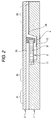
- Fig. 2 is a cross sectional view of Fig. 1 taken along line II-II.
- the cartridge for chemical reaction comprises a substrate 1 and an elastic member 2 overlaid on the substrate 1.
- This concave part produces space between the cartridge substrate 1 and the elastic member 2 to constitute chambers 21, 22, 23 for storing a solution, a supply part 24 for supplying a solution to a target molecule detecting chip 3 described later, and channels 25, 26, 27, 28 as shown in Figs. 1 and 2.
- the channel 25, the chamber 21, the channel 26, the chamber 22, the channel 27 and the supply part 24 are serially interconnected.
- the cartridge substrate 1 and the elastic member 2 are bonded together. This encloses a solution stored in the concave part inside the cartridge thus preventing leakage to the outside.
- a storage part 11 storing the target molecule detecting chip 3 and a discharge part 12 for storing a solution discharged from the target molecule detecting chip 3, the storage part 11 provided on the rear surface of the target molecule detecting chip 3 (on the bottom surface in Fig. 2).
- a support member 4 On the rear surface of an elastic member 2 is fixed a support member 4 for supporting the target molecule detecting chip 3.
- the target molecule detecting chip 3 stored in the storage part 11 is bonded to the cartridge substrate 1 and the support member 4 and fixed inside the cartridge.
- the target molecule detecting chip 3 is fixed inside the cartridge while preventing leakage of solution in the direction of thickness of the target molecule detecting chip 3 from around the target molecule detecting chip 3.
- the discharge part 12 of the cartridge substrate 1 is in communication with the channel 28.
- the target molecule detecting chip 3 is a penetration type chip that detects a target molecule by way of hybridization.
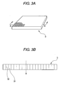
- Fig. 3 shows the structure of the target molecule detecting chip 3.
- Fig. 3A is a perspective view and Fig. 3B is a cross sectional view of Fig. 3A taken along line B-B.
- detection parts 31 to which probes corresponding to individual target molecules are fixed are two-dimensionally arranged and the detection parts 31 are segmented by partition walls 32.
- the detection parts 31 detect target molecules in a solution that penetrates the target molecule detecting chip 3 in its thickness direction (vertical direction in Fig. 3B) by way of hybridization.
- Fig. 4 shows the operation for solution transfer.
- a solution as a test target is previously injected into the chamber 21 formed in the cartridge. Injection of a solution is made by inserting an injection needle via the channel 25.
- the channel 25 has a plug (not shown) including an elastic body in an enclosed state. The plug is pierced with the injection needle when the solution is injected. With the solution injected, the injection needle is pulled out to stop the needle hole to secure the enclosed state.
- a roller 51 and a roller 52 provided in predetermined interval are used to press the elastic member 2 against the substrate 1 in order to move the roller 51 and the roller 52 in horizontal direction.
- the solution injected into the chamber 21 is fed to the supply part 24 via the channel 26, the chamber 22 and the channel 27.
- the solution penetrates the detection parts 31 of the target molecule detecting chip 3 downward from the supply part 24 and reaches the chamber 23 via the discharge part 12 and the channel 28.
- a heater HT may be used to keep the temperature of the solution to a value suitable for hybridization while hybridization is under way.
- a predetermined read unit is used to detect target molecules that have undergone hybridization on the target molecule detecting chip 3.
- Target molecules may be detected inside the cartridge without the target molecule detecting chip 3 being removed therefrom. Alternatively, target molecules may be detected after the target molecule detecting chip 3 has been removed from the cartridge.
- a variety of penetration type chips may be used. Examples include a chip having a probe immobilized on a porous filter (product name: Pam Gene/PAM Microarray System) from Olympus Corporation and a fiber type chip such as GenopalTM from Mitsubishi Rayon Co.,Ltd.
- a porous filter product name: Pam Gene/PAM Microarray System
- a fiber type chip such as GenopalTM from Mitsubishi Rayon Co.,Ltd.
- a collecting part 61 for storing a solution to be tested there may be provided a pretreatment liquid storage part 62 for previously storing a pretreatment liquid to be mixed with the solution to be tested, and a cleaning solution storage part 63 for previously storing a cleaning liquid.
- These parts may be connected to each other by way of the channel 64.
- roller movement delivers the solution to be tested from the collecting part 61 and the pretreatment liquid from the pretreatment storage part 62 to mix them for later labeling.
- hybridization takes place on the chip.
- roller movement discharges the cleaning solution from the cleaning solution storage part 63 to wash non-hybridized molecules together with the solution. After that, target molecules hybridized on the chip are detected. Details of such operation are described in JP-A-2004-226068 .
- the target molecule detecting chip 3 may be fixed by fitting to a component member of the cartridge as shown in Fig. 6.
- the target molecule detecting chip 3 is supported via the seals parts 71 through 74 to mechanically fix the target molecule detecting chip 3 inside the cartridge while preventing leakage of the solution in the direction of thickness of the target molecule detecting chip 3 from around the target molecule detecting chip 3.
- Exemplary methods for detecting target molecules hybridized on the chip include a detection method using light such as a method that is based on fluorescent measurement using laser beams and a method using a current.
- a detection method using light such as a method that is based on fluorescent measurement using laser beams
- a method using a current it is possible to provide on the cartridge a connector for supplying a current into the chip inside the cartridge from the outside. In this case, the connector is attached while keeping the hermetical sealing of the cartridge.
- Fig. 7 shows an example where electrodes are formed on the cartridge used to apply an electric field to the chip 3 to migrate charged molecules to accelerate hybridization by the effect of electrophoresis to the charged molecules such as DNA or RNA.
- an electrode 81 and an electrode 82 are respectively provided on the inner surface of a substrate 1B and the inner surface of an elastic member 2B.
- the electrode 81 and the electrode 82 are made connectable to an external power source via connectors provided on the cartridge.
- a chip 3A with conductivity and use the chip 3A as an electrode it is possible to provide a chip 3A with conductivity and use the chip 3A as an electrode.
- the chip 3A, the electrode 91 and the electrode 92 are connectable to an external power source via connectors provided on the cartridge.
- an electrode for accelerating hybridization comes in direct contact with a solution so that it is likely to be degraded thus accompanied by cumbersome work such as cleaning.
- This embodiment uses a cartridge disposed of each time a test is conducted so that it no longer has problems of degradation and maintenance of electrodes.
- the invention is also applicable to a plane type chip.
- Embodiment 2 of the cartridge for chemical reaction according to the invention will be described referring to Fig. 9.
- This embodiment illustrates an exemplary cartridge for chemical reaction using a plane type chip.
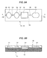
- Fig. 9A is a plan view of the cartridge for chemical reaction according to this embodiment.
- Fig. 9B is a cross sectional view of Fig. 9A taken along line IXb-IXb.
- the cartridge for chemical reaction comprises a substrate 101 and an elastic member 102 overlaid on the substrate 101.
- This concave part produces space between the cartridge substrate 101 and the elastic member 102 to constitute chambers 121, 122, 123 for storing a solution, a storage part 124 for storing a chip 103 described later, and channels 125, 126, 127, 128.
- the channel 125, the chamber 121, the channel 126, the chamber 122, the channel 127, the storage part 124, the channel 128 and the chamber 123 serially interconnected.
- the cartridge substrate 101 and the elastic member 102 are bonded together. This encloses a solution stored in the concave part inside the cartridge thus preventing leakage to the outside.
- a target molecule detecting chip 103 in the substrate 101 is stored a target molecule detecting chip 103.
- the chip 103 is a plane type chip that detects a target molecule by way of hybridization.
- On the front surface (upper surface in Fig. 9B) of the chip 103 are two-dimensionally arranged detection parts to which probes corresponding to individual target molecules are fixed.
- a solution as a test target is previously injected into the chamber 121 formed in the cartridge. Injection of a solution is made by inserting an injection needle via the channel 125.
- the channel 125 has a plug (not shown) including an elastic body in an enclosed state. The plug is pierced with the injection needle when the solution is injected. With the solution injected, the injection needle is pulled out to stop the needle hole to secure the enclosed state.
- rollers are moved rightward while the rollers are used to press the elastic member 102 against the substrate 101.
- the solution injected into the chamber 121 is fed to the storage part 124 via the channel 126, the chamber 122, and the channel 127.
- the solution fed into the storage part 124 causes hybridization on the chip 103.
- the solution may be repeatedly supplied on the chip 103 by reciprocating the rollers.
- a predetermined read unit is used to detect target molecules that have undergone hybridization on the target molecule detecting chip 103.
- Target molecules may be detected inside the cartridge without the target molecule detecting chip 103 being removed therefrom. Alternatively, target molecules may be detected after the target molecule detecting chip 103 has been removed from the cartridge.
- JP-A-2004-226068 detection is made with a slide glass type microarray and a cartridge housing the entire target molecule detecting chip is not used. With the invention, the entire chip is housed to provide perfect sealing. Note that the operation for hybridization disclosed in JP-A-2004-226068 may be also applied to the invention.
- Embodiment 1 it is possible to provide a collecting part for storing a solution to be tested and a cleaning solution storage part for previously storing a cleaning liquid may be provided.
- Embodiment 1 Concerning the method for fixing the chip 103, the method for detecting target molecules and formation of electrodes on a cartridge, the structure of Embodiment 1 may be applied to this embodiment.
- target molecules are not limited.
- target molecules may be DNA, RNA, protein and metabolites.
- the invention is not limited to detection of biopolymers but is applicable to general chromatography.
- the scope of the invention is not limited to the above embodiments.
- the invention is widely applicable to a cartridge for chemical reaction that causes chemical reaction by way of deformation caused by external forces to deliver an internal solution.
Landscapes
- Chemical & Material Sciences (AREA)
- Health & Medical Sciences (AREA)
- Dispersion Chemistry (AREA)
- Analytical Chemistry (AREA)
- General Health & Medical Sciences (AREA)
- Hematology (AREA)
- Clinical Laboratory Science (AREA)
- Chemical Kinetics & Catalysis (AREA)
- Apparatus Associated With Microorganisms And Enzymes (AREA)
Abstract
The cartridge for chemical reaction according to the invention is a cartridge for chemical reaction that causes chemical reaction by feeding an internal liquid by way of deformation caused by external forces. The entirety of a target molecule detecting chip is housed in the cartridge for chemical reaction. According to the cartridge for chemical reaction, the entire target molecule detecting chip is housed in the cartridge for chemical reaction so that it supports various forms of target molecule detecting chips. The target molecule detecting chip may be a penetration type chip that allows a solution including target molecules to penetrate the target molecule detecting chip. In this case, the solution may pass inside the penetration type chip by way of deformation of the cartridge for chemical reaction caused by external forces applied to the cartridge for chemical reaction.
Description
- The present invention relates to a cartridge for chemical reaction that causes chemical reaction by feeding an internal liquid by way of deformation caused by external forces.
- A cartridge has been proposed that supplies an internal liquid by way of deformation caused by external forces with a biopolymer microarray of a slide glass type inserted (refer to Patent Reference 1).
[Patent Reference 1]JP-A-2004-226068 - In recent years, a target molecule detecting chip has been developed where detection parts of a large number of different target molecules are densely integrated. Such a molecule detecting chip is formed in an extremely compact form when considering the number of detectable target molecules. Thus, a compact cartridge for chemical reaction is in need that supports such a target molecule detecting chip.
- As one type of target molecule detecting chip, a penetration type chip has been developed having a structure that allows a solution to penetrate the chip in its thickness direction. The problem is that the related art cartridge does not support such a penetration type chip. A system has been developed that uses apparatus employing a pump to feed a solution to a penetration type chip to perform hybridization although the result is large-sized apparatus and an expensive system.
- An object of the invention is to provide a cartridge for chemical reaction that supports detection of a target molecule by using a target molecule detecting chip and that has a compact size.
- The present invention provides a cartridge for chemical reaction that causes chemical reaction by feeding an internal liquid by way of deformation caused by external forces, including: a target molecule detecting chip which is entirely housed in the cartridge for chemical reaction, and channels for feeding the internal liquid, being connected to the target molecule detecting chip.
- According to the cartridge for chemical reaction of the present invention, the target molecule detecting chip is entirely housed in the cartridge for chemical reaction so that the cartridge for chemical reaction supports various forms of target molecule detecting chips.
- The target molecule detecting chip may be a penetration type chip that allows a solution including a target molecule to penetrate the chip.
- The target molecule detecting chip may allow the solution to pass through the inside of the penetration type chip by way of deformation caused by external forces applied to the cartridge for chemical reaction.
- The present invention provides a cartridge for chemical reaction that causes chemical reaction by feeding an internal liquid by way of deformation caused by external forces, the cartridge for chemical reaction including: a penetration type target molecule detecting chip that allows a solution including a target molecule to penetrate the chip, and channels for feeding the internal liquid, being connected to the target molecule detecting chip, wherein the target molecule detecting chip allows the solution to pass through the inside of the target molecule detecting chip by way of deformation caused by external forces applied to the cartridge for chemical reaction.
- According to the cartridge for chemical reaction of the present invention, deformation of the cartridge for chemical reaction caused by external forces applied to the cartridge for chemical reaction allows a solution to pass inside a penetration type target molecule detecting chip. It is thus possible to detect a target molecule with a penetration type target molecule detecting chip by applying external forces.
- The target molecule detecting chip may detect any one of DNA, RNA, protein and metabolite as a target molecule.
- The cartridge for chemical reaction may include electrodes for applying an electric field to charged molecules inside the cartridge for chemical reaction.
- The cartridge for chemical reaction according to the invention houses the entire target molecule detecting chip inside the cartridge for chemical reaction so that it supports various forms of target molecule detecting chips.
- Deformation of the inventive cartridge for chemical reaction caused by external forces applied to the cartridge for chemical reaction allows a solution to pass inside a penetration type target molecule detecting chip. It is thus possible to detect a target molecule with a penetration type target molecule detecting chip by applying external forces.
-
- Fig. 1 is a plan view of the structure of the cartridge for chemical reaction according to
Embodiment 1. - Fig. 2 is a cross sectional view of Fig. 1 taken along line II-II.
- Fig. 3A is a perspective view of the structure of a target molecule detecting chip.
- Fig. 3B is a cross sectional view of Fig. 3A taken along line B-B.
- Fig. 4 shows the operation for solution transfer.
- Fig. 5 shows an example where a pretreatment liquid storage part for previously storing a pretreatment liquid and a cleaning solution storage part for previously storing a cleaning liquid.
- Fig. 6 shows an example where a target molecule detecting chip is fitted to a component member of the cartridge.
- Fig. 7 shows an example where electrodes for accelerating hybridization are formed on the cartridge.
- Fig. 8 shows an example where the chip is used as an electrode.
- Fig. 9A is a plan view of the structure of the cartridge for chemical reaction according to
Embodiment 2. - Fig. 9B is a cross sectional view of Fig. 9A taken along line IXb-IXb.
- Embodiments of the cartridge for chemical reaction according to the invention will be described.
-
Embodiment 1 of the cartridge for chemical reaction according to the invention will be described referring to Figs. 1 through 8. - Fig. 1 is a plan view of the structure of the cartridge for chemical reaction according to this embodiment. Fig. 2 is a cross sectional view of Fig. 1 taken along line II-II.
- As shown in Figs. 1 and 2, the cartridge for chemical reaction according to this embodiment comprises a
substrate 1 and anelastic member 2 overlaid on thesubstrate 1. - On the rear surface (bottom surface in Fig. 2) of the
elastic member 2 is formed a concave part of a predetermined shape recessed toward the front surface (top surface in Fig. 2). This concave part produces space between thecartridge substrate 1 and theelastic member 2 to constitutechambers supply part 24 for supplying a solution to a targetmolecule detecting chip 3 described later, andchannels channel 25, thechamber 21, thechannel 26, thechamber 22, thechannel 27 and thesupply part 24 are serially interconnected. - In the areas other than the concave part, the
cartridge substrate 1 and theelastic member 2 are bonded together. This encloses a solution stored in the concave part inside the cartridge thus preventing leakage to the outside. - As shown in Figs. 1 and 2, on the
substrate 1 are formed astorage part 11 storing the targetmolecule detecting chip 3 and adischarge part 12 for storing a solution discharged from the targetmolecule detecting chip 3, thestorage part 11 provided on the rear surface of the target molecule detecting chip 3 (on the bottom surface in Fig. 2). On the rear surface of anelastic member 2 is fixed asupport member 4 for supporting the targetmolecule detecting chip 3. The targetmolecule detecting chip 3 stored in thestorage part 11 is bonded to thecartridge substrate 1 and thesupport member 4 and fixed inside the cartridge. - With this structure, the target
molecule detecting chip 3 is fixed inside the cartridge while preventing leakage of solution in the direction of thickness of the targetmolecule detecting chip 3 from around the targetmolecule detecting chip 3. As shown in Fig. 2, thedischarge part 12 of thecartridge substrate 1 is in communication with thechannel 28. - The target
molecule detecting chip 3 is a penetration type chip that detects a target molecule by way of hybridization. - Fig. 3 shows the structure of the target
molecule detecting chip 3. Fig. 3A is a perspective view and Fig. 3B is a cross sectional view of Fig. 3A taken along line B-B. As shown in Figs. 3A and 3B, in the targetmolecule detecting chip 3,detection parts 31 to which probes corresponding to individual target molecules are fixed are two-dimensionally arranged and thedetection parts 31 are segmented bypartition walls 32. Thedetection parts 31 detect target molecules in a solution that penetrates the targetmolecule detecting chip 3 in its thickness direction (vertical direction in Fig. 3B) by way of hybridization. - Next, operation of solution transfer in the cartridge will be described. Fig. 4 shows the operation for solution transfer.
- A solution as a test target is previously injected into the
chamber 21 formed in the cartridge. Injection of a solution is made by inserting an injection needle via thechannel 25. Thechannel 25 has a plug (not shown) including an elastic body in an enclosed state. The plug is pierced with the injection needle when the solution is injected. With the solution injected, the injection needle is pulled out to stop the needle hole to secure the enclosed state. - Next, as shown in Figs. 4 and 1, a
roller 51 and aroller 52 provided in predetermined interval are used to press theelastic member 2 against thesubstrate 1 in order to move theroller 51 and theroller 52 in horizontal direction. With this operation, the solution injected into thechamber 21 is fed to thesupply part 24 via thechannel 26, thechamber 22 and thechannel 27. As shown in Fig. 4, the solution penetrates thedetection parts 31 of the targetmolecule detecting chip 3 downward from thesupply part 24 and reaches thechamber 23 via thedischarge part 12 and thechannel 28. - Next, with the
roller 51 and theroller 52 are reciprocated in a number of predetermined times while pressed against theelastic member 2 in a horizontal direction in Fig. 4. With this operation, the solution is reciprocally transferred between thechamber 22 and thechamber 23 so as to cause thedetection parts 31 of the targetmolecule detecting chip 3 being passed through a plurality times by the solution. This provides sufficient chances of the solution coming into contact with thedetection part 31 required for hybridization. This also reduces hybridization errors caused by a molecule other than a target molecule. Reciprocation of theroller 51 and theroller 52 may be omitted as long as appropriate as conditions for hybridization. - As shown in Fig. 4, a heater HT may be used to keep the temperature of the solution to a value suitable for hybridization while hybridization is under way.
- After the operation for hybridization is over, a predetermined read unit is used to detect target molecules that have undergone hybridization on the target
molecule detecting chip 3. Target molecules may be detected inside the cartridge without the targetmolecule detecting chip 3 being removed therefrom. Alternatively, target molecules may be detected after the targetmolecule detecting chip 3 has been removed from the cartridge. - According to this embodiment, it is possible to perform hybridization by way of a target molecule detecting chip inside a cartridge. A solution is transferred to penetrate the target molecule detecting chip thus supporting a penetration type chip.
- A variety of penetration type chips may be used. Examples include a chip having a probe immobilized on a porous filter (product name: Pam Gene/PAM Microarray System) from Olympus Corporation and a fiber type chip such as Genopal™ from Mitsubishi Rayon Co.,Ltd.
- As shown in Fig. 5, there may be provided a collecting
part 61 for storing a solution to be tested, a pretreatmentliquid storage part 62 for previously storing a pretreatment liquid to be mixed with the solution to be tested, and a cleaningsolution storage part 63 for previously storing a cleaning liquid. These parts may be connected to each other by way of thechannel 64. - In this case, roller movement delivers the solution to be tested from the collecting
part 61 and the pretreatment liquid from thepretreatment storage part 62 to mix them for later labeling. Next, hybridization takes place on the chip. After the hybridization, roller movement discharges the cleaning solution from the cleaningsolution storage part 63 to wash non-hybridized molecules together with the solution. After that, target molecules hybridized on the chip are detected. Details of such operation are described inJP-A-2004-226068 - While the target
molecule detecting chip 3 is fixed by way of bonding in this embodiment, the targetmolecule detecting chip 3 may be fixed by fitting to a component member of the cartridge as shown in Fig. 6. In the example of Fig. 6, the targetmolecule detecting chip 3 is supported via theseals parts 71 through 74 to mechanically fix the targetmolecule detecting chip 3 inside the cartridge while preventing leakage of the solution in the direction of thickness of the targetmolecule detecting chip 3 from around the targetmolecule detecting chip 3. - Exemplary methods for detecting target molecules hybridized on the chip include a detection method using light such as a method that is based on fluorescent measurement using laser beams and a method using a current. In case the method using a current is employed, it is possible to provide on the cartridge a connector for supplying a current into the chip inside the cartridge from the outside. In this case, the connector is attached while keeping the hermetical sealing of the cartridge.
- Fig. 7 shows an example where electrodes are formed on the cartridge used to apply an electric field to the
chip 3 to migrate charged molecules to accelerate hybridization by the effect of electrophoresis to the charged molecules such as DNA or RNA. In the example of Fig. 7, anelectrode 81 and anelectrode 82 are respectively provided on the inner surface of asubstrate 1B and the inner surface of anelastic member 2B. Theelectrode 81 and theelectrode 82 are made connectable to an external power source via connectors provided on the cartridge. In this case, it is possible to invert the electric field to accelerate hybridization by repeatedly inverting a voltage applied across theelectrode 81 and theelectrode 82, and also reduce hybridization errors. As shown in Fig. 8, it is possible to provide achip 3A with conductivity and use thechip 3A as an electrode. In this case, thechip 3A, theelectrode 91 and theelectrode 92 are connectable to an external power source via connectors provided on the cartridge. - In general, an electrode for accelerating hybridization comes in direct contact with a solution so that it is likely to be degraded thus accompanied by cumbersome work such as cleaning. This embodiment uses a cartridge disposed of each time a test is conducted so that it no longer has problems of degradation and maintenance of electrodes.
- While a penetration type chip is used in the embodiment, the invention is also applicable to a plane type chip.
-
Embodiment 2 of the cartridge for chemical reaction according to the invention will be described referring to Fig. 9. This embodiment illustrates an exemplary cartridge for chemical reaction using a plane type chip. - Fig. 9A is a plan view of the cartridge for chemical reaction according to this embodiment. Fig. 9B is a cross sectional view of Fig. 9A taken along line IXb-IXb.
- As shown in Figs. 9A and 9B, the cartridge for chemical reaction according to this embodiment comprises a
substrate 101 and anelastic member 102 overlaid on thesubstrate 101. - On the rear surface (bottom surface in Fig. 9B) of the
elastic member 102 is formed a concave part of a predetermined shape recessed toward the front surface (top surface in Fig. 9B). This concave part produces space between thecartridge substrate 101 and theelastic member 102 to constitutechambers storage part 124 for storing achip 103 described later, andchannels channel 125, thechamber 121, thechannel 126, thechamber 122, thechannel 127, thestorage part 124, thechannel 128 and thechamber 123 serially interconnected. - In the areas other than the concave part, the
cartridge substrate 101 and theelastic member 102 are bonded together. This encloses a solution stored in the concave part inside the cartridge thus preventing leakage to the outside. - As shown in Figs. 9A and 9B, in the
substrate 101 is stored a targetmolecule detecting chip 103. - The
chip 103 is a plane type chip that detects a target molecule by way of hybridization. On the front surface (upper surface in Fig. 9B) of thechip 103 are two-dimensionally arranged detection parts to which probes corresponding to individual target molecules are fixed. - Next, operation of solution transfer in the cartridge will be described.
- A solution as a test target is previously injected into the
chamber 121 formed in the cartridge. Injection of a solution is made by inserting an injection needle via thechannel 125. Thechannel 125 has a plug (not shown) including an elastic body in an enclosed state. The plug is pierced with the injection needle when the solution is injected. With the solution injected, the injection needle is pulled out to stop the needle hole to secure the enclosed state. - Next, same as
Embodiment 1, rollers are moved rightward while the rollers are used to press theelastic member 102 against thesubstrate 101. With this operation, the solution injected into thechamber 121 is fed to thestorage part 124 via thechannel 126, thechamber 122, and thechannel 127. - The solution fed into the
storage part 124 causes hybridization on thechip 103. Same asEmbodiment 1, the solution may be repeatedly supplied on thechip 103 by reciprocating the rollers. - After the operation for hybridization is over, a predetermined read unit is used to detect target molecules that have undergone hybridization on the target
molecule detecting chip 103. Target molecules may be detected inside the cartridge without the targetmolecule detecting chip 103 being removed therefrom. Alternatively, target molecules may be detected after the targetmolecule detecting chip 103 has been removed from the cartridge. - According to this embodiment, it is possible to perform hybridization by way of a plane type chip inside a cartridge. In
JP-A-2004-226068 JP-A-2004-226068 - Same as
Embodiment 1, it is possible to provide a collecting part for storing a solution to be tested and a cleaning solution storage part for previously storing a cleaning liquid may be provided. - Concerning the method for fixing the
chip 103, the method for detecting target molecules and formation of electrodes on a cartridge, the structure ofEmbodiment 1 may be applied to this embodiment. - In the foregoing embodiments, types of a target molecule are not limited. For example, target molecules may be DNA, RNA, protein and metabolites. The invention is not limited to detection of biopolymers but is applicable to general chromatography.
- The scope of the invention is not limited to the above embodiments. The invention is widely applicable to a cartridge for chemical reaction that causes chemical reaction by way of deformation caused by external forces to deliver an internal solution.
Claims (8)
- A cartridge for chemical reaction that causes chemical reaction by feeding an internal liquid by way of deformation caused by external forces, comprising:a target molecule detecting chip which is entirely housed in the cartridge for chemical reaction, andchannels for feeding the internal liquid, being connected to the target molecule detecting chip.
- The cartridge for chemical reaction according to claim 1, wherein
the target molecule detecting chip is a penetration type chip that allows a solution including a target molecule to penetrate the chip. - The cartridge for chemical reaction according to claim 2, wherein
the target molecule detecting chip allows the solution to pass through the inside of the penetration type chip by way of deformation caused by external forces applied to the cartridge for chemical reaction. - A cartridge for chemical reaction that causes chemical reaction by feeding an internal liquid by way of deformation caused by external forces,
the cartridge for chemical reaction comprising:a penetration type target molecule detecting chip that allows a solution including a target molecule to penetrate the chip, andchannels for feeding the internal liquid, being connected to the target molecule detecting chip, whereinthe target molecule detecting chip allows the solution to pass through the inside of the target molecule detecting chip by way of deformation caused by external forces applied to the cartridge for chemical reaction. - The cartridge for chemical reaction according to claim 1, wherein
the target molecule detecting chip detects any one of DNA, RNA, protein and metabolite as a target molecule. - The cartridge for chemical reaction according to claim 1, wherein
the cartridge for chemical reaction includes electrodes for applying an electric field to charged molecules inside the cartridge for chemical reaction. - The cartridge for chemical reaction according to claim 4, wherein
the target molecule detecting chip detects any one of DNA, RNA, protein and metabolite as a target molecule. - The cartridge for chemical reaction according to claim 4, wherein
the cartridge for chemical reaction includes electrodes for applying an electric field to charged molecules inside the cartridge for chemical reaction.
Applications Claiming Priority (1)
| Application Number | Priority Date | Filing Date | Title |
|---|---|---|---|
| JP2005163824A JP4872244B2 (en) | 2005-06-03 | 2005-06-03 | Chemical reaction cartridge |
Publications (1)
| Publication Number | Publication Date |
|---|---|
| EP1728555A2 true EP1728555A2 (en) | 2006-12-06 |
Family
ID=37011923
Family Applications (1)
| Application Number | Title | Priority Date | Filing Date |
|---|---|---|---|
| EP06011407A Withdrawn EP1728555A2 (en) | 2005-06-03 | 2006-06-01 | Cartridge for chemical reaction |
Country Status (4)
| Country | Link |
|---|---|
| US (1) | US20060275813A1 (en) |
| EP (1) | EP1728555A2 (en) |
| JP (1) | JP4872244B2 (en) |
| CN (1) | CN100436600C (en) |
Families Citing this family (10)
| Publication number | Priority date | Publication date | Assignee | Title |
|---|---|---|---|---|
| KR100843146B1 (en) * | 2006-12-20 | 2008-07-02 | 삼성전자주식회사 | Biochip kit and biosample test method |
| CN103157400B (en) | 2007-06-21 | 2014-12-24 | 简·探针公司 | Instrument and method for exposing container to multiple areas |
| US9957553B2 (en) | 2012-10-24 | 2018-05-01 | Genmark Diagnostics, Inc. | Integrated multiplex target analysis |
| US20140322706A1 (en) | 2012-10-24 | 2014-10-30 | Jon Faiz Kayyem | Integrated multipelx target analysis |
| CN107866286A (en) | 2013-03-15 | 2018-04-03 | 金马克诊断股份有限公司 | Systems, methods and apparatus for manipulating deformable fluid containers |
| USD881409S1 (en) | 2013-10-24 | 2020-04-14 | Genmark Diagnostics, Inc. | Biochip cartridge |
| US9498778B2 (en) | 2014-11-11 | 2016-11-22 | Genmark Diagnostics, Inc. | Instrument for processing cartridge for performing assays in a closed sample preparation and reaction system |
| US10005080B2 (en) | 2014-11-11 | 2018-06-26 | Genmark Diagnostics, Inc. | Instrument and cartridge for performing assays in a closed sample preparation and reaction system employing electrowetting fluid manipulation |
| US9598722B2 (en) | 2014-11-11 | 2017-03-21 | Genmark Diagnostics, Inc. | Cartridge for performing assays in a closed sample preparation and reaction system |
| KR102592612B1 (en) * | 2021-08-24 | 2023-10-24 | (주)옵토레인 | Molecular diagnostic cartridge |
Citations (1)
| Publication number | Priority date | Publication date | Assignee | Title |
|---|---|---|---|---|
| JP2004226068A (en) | 2003-01-20 | 2004-08-12 | Yokogawa Electric Corp | Biochip cartridge |
Family Cites Families (12)
| Publication number | Priority date | Publication date | Assignee | Title |
|---|---|---|---|---|
| US4673657A (en) * | 1983-08-26 | 1987-06-16 | The Regents Of The University Of California | Multiple assay card and system |
| US6309602B1 (en) * | 1993-11-01 | 2001-10-30 | Nanogen, Inc. | Stacked, reconfigurable system for electrophoretic transport of charged materials |
| CN1115174C (en) * | 1999-02-12 | 2003-07-23 | 复旦大学 | Biological chip on electric conductive silicon glass carrier and preparation thereof |
| EP1146331B1 (en) * | 1999-10-20 | 2008-09-10 | Shigeori Takenaka | Gene detecting chip, detector, and detecting method |
| JP2001127242A (en) * | 1999-10-22 | 2001-05-11 | Seiko Epson Corp | Semiconductor chip, multi-chip package, semiconductor device, electronic device, and manufacturing method thereof |
| CA2364381C (en) * | 1999-12-22 | 2009-03-10 | Gene Logic, Inc. | Flow-thru chip cartridge, chip holder, system and method thereof |
| US7524459B2 (en) * | 2002-01-24 | 2009-04-28 | California Institute Of Technology In Pasadena | Optoelectronic and microfluidic integration for miniaturized spectroscopic devices |
| US20040137607A1 (en) * | 2003-01-09 | 2004-07-15 | Yokogawa Electric Corporation | Biochip cartridge |
| US7854897B2 (en) * | 2003-05-12 | 2010-12-21 | Yokogawa Electric Corporation | Chemical reaction cartridge, its fabrication method, and a chemical reaction cartridge drive system |
| JP4399766B2 (en) * | 2003-07-04 | 2010-01-20 | 横河電機株式会社 | Chemical reaction cartridge |
| JP2004340895A (en) * | 2003-05-19 | 2004-12-02 | Olympus Corp | Inspection container and detection device of organism-related substance |
| JP2005055316A (en) * | 2003-08-05 | 2005-03-03 | Olympus Corp | Solution removing method and solution absorbing tool in living body related material reaction test |
-
2005
- 2005-06-03 JP JP2005163824A patent/JP4872244B2/en not_active Expired - Fee Related
-
2006
- 2006-06-01 EP EP06011407A patent/EP1728555A2/en not_active Withdrawn
- 2006-06-02 CN CNB2006100833453A patent/CN100436600C/en not_active Expired - Fee Related
- 2006-06-05 US US11/446,225 patent/US20060275813A1/en not_active Abandoned
Patent Citations (1)
| Publication number | Priority date | Publication date | Assignee | Title |
|---|---|---|---|---|
| JP2004226068A (en) | 2003-01-20 | 2004-08-12 | Yokogawa Electric Corp | Biochip cartridge |
Also Published As
| Publication number | Publication date |
|---|---|
| CN1880438A (en) | 2006-12-20 |
| JP2006337238A (en) | 2006-12-14 |
| US20060275813A1 (en) | 2006-12-07 |
| CN100436600C (en) | 2008-11-26 |
| JP4872244B2 (en) | 2012-02-08 |
Similar Documents
| Publication | Publication Date | Title |
|---|---|---|
| USRE48993E1 (en) | Fluidic system for reagent delivery to a flow cell | |
| EP1997888A1 (en) | Nucleic acid detection cassette and nucleic acid detection apparatus | |
| US20060275813A1 (en) | Cartridge for chemical reaction | |
| EP3190169A1 (en) | Nucleic acid detection cassette | |
| US20160216235A1 (en) | Electrophoresis Medium Receptacle and Electrophoresis Apparatus | |
| CN113302487B (en) | An electrophoresis device that enables multiple samples to be electrophoresed independently | |
| EP1738828B1 (en) | Biochemical reaction cassette | |
| JP4261546B2 (en) | Electrophoresis apparatus and electrophoresis method | |
| US6991311B2 (en) | Apparatus and method for introducing micro-volume liquid | |
| JP7361900B2 (en) | Interface for automatic fluid injection | |
| US7527720B2 (en) | Device for electrophoresis, electrophoresis equipment, electrophoretic method, and specimen detection method | |
| JP6855155B2 (en) | Nucleic acid detection cassette | |
| JP5978147B2 (en) | Biological material analyzer | |
| JP6855154B2 (en) | Nucleic acid detection cassette | |
| JP4723891B2 (en) | Hybridization cartridge, hybridization apparatus, and hybridization method | |
| JP6953501B2 (en) | Nucleic acid detection cassette | |
| JP2024110055A (en) | Nucleic acid testing device and its use | |
| JP2004226068A (en) | Biochip cartridge | |
| JP2016053480A (en) | Nucleic acid detection cassette | |
| HK40096464B (en) | Fluidic system for reagent delivery to a flow cell | |
| HK40096464A (en) | Fluidic system for reagent delivery to a flow cell | |
| HK1219499B (en) | Fluidic system for reagent delivery to a flow cell |
Legal Events
| Date | Code | Title | Description |
|---|---|---|---|
| PUAI | Public reference made under article 153(3) epc to a published international application that has entered the european phase |
Free format text: ORIGINAL CODE: 0009012 |
|
| AK | Designated contracting states |
Kind code of ref document: A2 Designated state(s): AT BE BG CH CY CZ DE DK EE ES FI FR GB GR HU IE IS IT LI LT LU LV MC NL PL PT RO SE SI SK TR |
|
| AX | Request for extension of the european patent |
Extension state: AL BA HR MK YU |
|
| STAA | Information on the status of an ep patent application or granted ep patent |
Free format text: STATUS: THE APPLICATION HAS BEEN WITHDRAWN |
|
| 18W | Application withdrawn |
Effective date: 20090625 |