EP1727447B1 - Method for manufacturing a cot - Google Patents
Method for manufacturing a cot Download PDFInfo
- Publication number
- EP1727447B1 EP1727447B1 EP05706123A EP05706123A EP1727447B1 EP 1727447 B1 EP1727447 B1 EP 1727447B1 EP 05706123 A EP05706123 A EP 05706123A EP 05706123 A EP05706123 A EP 05706123A EP 1727447 B1 EP1727447 B1 EP 1727447B1
- Authority
- EP
- European Patent Office
- Prior art keywords
- plastic
- finished
- securing
- fabric
- mold
- Prior art date
- Legal status (The legal status is an assumption and is not a legal conclusion. Google has not performed a legal analysis and makes no representation as to the accuracy of the status listed.)
- Expired - Lifetime
Links
Images


Classifications
-
- A—HUMAN NECESSITIES
- A47—FURNITURE; DOMESTIC ARTICLES OR APPLIANCES; COFFEE MILLS; SPICE MILLS; SUCTION CLEANERS IN GENERAL
- A47D—FURNITURE SPECIALLY ADAPTED FOR CHILDREN
- A47D13/00—Other nursery furniture
- A47D13/06—Children's play- pens
-
- A—HUMAN NECESSITIES
- A47—FURNITURE; DOMESTIC ARTICLES OR APPLIANCES; COFFEE MILLS; SPICE MILLS; SUCTION CLEANERS IN GENERAL
- A47C—CHAIRS; SOFAS; BEDS
- A47C7/00—Parts, details, or accessories of chairs or stools
- A47C7/02—Seat parts
- A47C7/28—Seat parts with tensioned springs, e.g. of flat type
- A47C7/282—Seat parts with tensioned springs, e.g. of flat type with mesh-like supports, e.g. elastomeric membranes
-
- B—PERFORMING OPERATIONS; TRANSPORTING
- B29—WORKING OF PLASTICS; WORKING OF SUBSTANCES IN A PLASTIC STATE IN GENERAL
- B29C—SHAPING OR JOINING OF PLASTICS; SHAPING OF MATERIAL IN A PLASTIC STATE, NOT OTHERWISE PROVIDED FOR; AFTER-TREATMENT OF THE SHAPED PRODUCTS, e.g. REPAIRING
- B29C45/00—Injection moulding, i.e. forcing the required volume of moulding material through a nozzle into a closed mould; Apparatus therefor
- B29C45/14—Injection moulding, i.e. forcing the required volume of moulding material through a nozzle into a closed mould; Apparatus therefor incorporating preformed parts or layers, e.g. injection moulding around inserts or for coating articles
- B29C45/14065—Positioning or centering articles in the mould
-
- B—PERFORMING OPERATIONS; TRANSPORTING
- B29—WORKING OF PLASTICS; WORKING OF SUBSTANCES IN A PLASTIC STATE IN GENERAL
- B29C—SHAPING OR JOINING OF PLASTICS; SHAPING OF MATERIAL IN A PLASTIC STATE, NOT OTHERWISE PROVIDED FOR; AFTER-TREATMENT OF THE SHAPED PRODUCTS, e.g. REPAIRING
- B29C45/00—Injection moulding, i.e. forcing the required volume of moulding material through a nozzle into a closed mould; Apparatus therefor
- B29C45/14—Injection moulding, i.e. forcing the required volume of moulding material through a nozzle into a closed mould; Apparatus therefor incorporating preformed parts or layers, e.g. injection moulding around inserts or for coating articles
- B29C45/14336—Coating a portion of the article, e.g. the edge of the article
-
- A—HUMAN NECESSITIES
- A61—MEDICAL OR VETERINARY SCIENCE; HYGIENE
- A61G—TRANSPORT, PERSONAL CONVEYANCES, OR ACCOMMODATION SPECIALLY ADAPTED FOR PATIENTS OR DISABLED PERSONS; OPERATING TABLES OR CHAIRS; CHAIRS FOR DENTISTRY; FUNERAL DEVICES
- A61G1/00—Stretchers
-
- B—PERFORMING OPERATIONS; TRANSPORTING
- B29—WORKING OF PLASTICS; WORKING OF SUBSTANCES IN A PLASTIC STATE IN GENERAL
- B29C—SHAPING OR JOINING OF PLASTICS; SHAPING OF MATERIAL IN A PLASTIC STATE, NOT OTHERWISE PROVIDED FOR; AFTER-TREATMENT OF THE SHAPED PRODUCTS, e.g. REPAIRING
- B29C45/00—Injection moulding, i.e. forcing the required volume of moulding material through a nozzle into a closed mould; Apparatus therefor
- B29C45/14—Injection moulding, i.e. forcing the required volume of moulding material through a nozzle into a closed mould; Apparatus therefor incorporating preformed parts or layers, e.g. injection moulding around inserts or for coating articles
- B29C45/14065—Positioning or centering articles in the mould
- B29C2045/14147—Positioning or centering articles in the mould using pins or needles penetrating through the insert
-
- B—PERFORMING OPERATIONS; TRANSPORTING
- B29—WORKING OF PLASTICS; WORKING OF SUBSTANCES IN A PLASTIC STATE IN GENERAL
- B29C—SHAPING OR JOINING OF PLASTICS; SHAPING OF MATERIAL IN A PLASTIC STATE, NOT OTHERWISE PROVIDED FOR; AFTER-TREATMENT OF THE SHAPED PRODUCTS, e.g. REPAIRING
- B29C65/00—Joining or sealing of preformed parts, e.g. welding of plastics materials; Apparatus therefor
- B29C65/56—Joining or sealing of preformed parts, e.g. welding of plastics materials; Apparatus therefor using mechanical means or mechanical connections, e.g. form-fits
- B29C65/60—Riveting or staking
- B29C65/606—Riveting or staking the rivets being integral with one of the parts to be joined, i.e. staking
-
- B—PERFORMING OPERATIONS; TRANSPORTING
- B29—WORKING OF PLASTICS; WORKING OF SUBSTANCES IN A PLASTIC STATE IN GENERAL
- B29K—INDEXING SCHEME ASSOCIATED WITH SUBCLASSES B29B, B29C OR B29D, RELATING TO MOULDING MATERIALS OR TO MATERIALS FOR MOULDS, REINFORCEMENTS, FILLERS OR PREFORMED PARTS, e.g. INSERTS
- B29K2313/00—Use of textile products or fabrics as reinforcement
-
- B—PERFORMING OPERATIONS; TRANSPORTING
- B29—WORKING OF PLASTICS; WORKING OF SUBSTANCES IN A PLASTIC STATE IN GENERAL
- B29K—INDEXING SCHEME ASSOCIATED WITH SUBCLASSES B29B, B29C OR B29D, RELATING TO MOULDING MATERIALS OR TO MATERIALS FOR MOULDS, REINFORCEMENTS, FILLERS OR PREFORMED PARTS, e.g. INSERTS
- B29K2713/00—Use of textile products or fabrics for preformed parts, e.g. for inserts
-
- B—PERFORMING OPERATIONS; TRANSPORTING
- B29—WORKING OF PLASTICS; WORKING OF SUBSTANCES IN A PLASTIC STATE IN GENERAL
- B29L—INDEXING SCHEME ASSOCIATED WITH SUBCLASS B29C, RELATING TO PARTICULAR ARTICLES
- B29L2031/00—Other particular articles
- B29L2031/753—Medical equipment; Accessories therefor
Definitions
- the present invention relates generally to plastic injection molding, and more particularly to a method of injection molding incorporating a fabric into a plastic molded cot assembly.
- plastic injection molding The general method of plastic injection molding is well known, including using a heated and sealed mold into which a liquid plastic material is introduced and then cured into a desired shape. Molded products have many material strengths. However, one drawback to traditional injection molding is the weakness inherent in an assembled article when the molded product transitions to a non-molded material, such as a fabric. Generally, a separate fastener mechanism has been required to attach the molded portion to a fabric, creating a potential point failure source between the fabric material and the plastic molded portion.
- a cot assembly In one typical cot, it is desired to attach the soft, middle portion, such as a woven material to a plastic molded end cap. Traditionally, this has required separate fasteners, such as posts, clips or brackets. However, when the fabric is placed under stress, for example by a person lying on the cot, the fabric tends to "pull away" from the fastener, and potentially tears or unravels, leading to a connection, failure.
- US-A-2003/0137179 describes a method for attaching a load bearing fabric to a support structure including the steps of pluring the fabric in a mold and molding the carrier in situ about the fabric.
- the present invention satisfies these needs, among others.
- the invention is defined by the features of claim 1.
- the cot includes a perimeter structure and a fabric middle portion, where one or two of the fabric ends are cured within plastic portions to form integrated edge pieces, such that each edge piece is easily connectable to the cot structure.
- the finished edge pieces spread the interface tension between the fabric and plastic portion substantially along the width of the edge piece.
- Certain embodiments of the present invention provide an improved method for manufacturing injection plastic molded cot assembly.
- the cot includes a perimeter structure and a fabric middle portion, where one, two or more of the fabric edges or ends are cured within plastic portions to form integrated end pieces, such that each end piece is easily connectable to the cot structure or frame.
- the finished piece preferably spreads the interface tension between the fabric and plastic portion, for example substantially along the width of an edge.
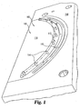
- Mold 100 includes a lower portion 110 and an upper portion 120.
- Lower portion 110 defines a molding lower cavity 112, having an height and width, illustrated as extending substantially the horizontal length of lower portion 110.
- the lower cavity is defined between an inner periphery 116 and an outer periphery 118.
- the lower cavity 112 may have a substantially constant width along its length.
- One or more pass-through members, such as placement stakes 114 extend upward within lower cavity 112.
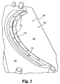
- Upper mold portion 120 defines an upper mold cavity 122, having an height and width, illustrated as extending substantially the horizontal length of upper portion 120.
- the upper cavity is defined between an inner periphery 126 and an outer periphery 128.
- Preferably the upper cavity 122 is symmetric to the lower cavity.
- One or more stake holes or recesses 124 are defined in upper cavity 122.
- Lower portion 110 and/or upper portion 120 define one or more injection ports 115 and/or 125 in fluid communication with the mold cavity.
- Lower cavity 112 and upper cavity 122 may have smooth or textured surfaces as desired, for example, a texture of a grid pattern to enhance gripping and traction.
- Lower portion 110 and upper portion 120 are made in matched sizes to be closed as mold 100.
- lower cavity 112 and upper cavity 122 form an enclosed cavity defining the size and shape of the intended injection molded product.
- outer peripheries 118 and 128 form a substantially sealed portion
- inner peripheries 116 and 126 form a substantially sealed portion, discussed further below.
- one or more stakes 114 extend through the enclosed cavity and the upper ends are received in matching recesses 124.
- Lower portion 110 and upper portion 120 may have posts, ridges, channels, recesses or similar indicia to allow the mold to align and close properly.
- Mold 100 is formed of known materials for an injection mold, typically steel or a similar metal.
- the mold clamping portions are preferably suitable to be placed under pressure and heated while a liquid plastic material is injected into the enclosed cavity and then cured by holding and cooling.
- a conventional injector or injectors are used.
- a fabric-type permeable material 20 is placed over lower mold portion 110 with a portion, such as end edge 22, aligned with and typically within lower cavity 112.
- openings, such as eyelets 25, defined in the material 20 are placed over pass-through members, such as stakes 114.
- the material is aligned to be substantially flat over the inner periphery 116, forming a continuous and uniform interface, without wrinkles.
- the mold 100 is then closed and clamped or placed under pressure, with upper portion 120 engaging lower portion 110.
- the inner peripheries of the mold portions are substantially sealed closely adjacent each other with pressure, while the material 20 remains substantially flat between them.
- a liquid plastic is then injected under pressure into the upper and lower cavity in the mold and air is removed or allowed to escape.
- liquid plastic is injected in the upper and lower cavities simultaneously.
- the fabric end 22 in the cavity "floats" in the injected material as the cavity is filled and the liquid plastic permeates the fabric material.
- the liquid plastic includes portions at least partially above and below the fabric material with a plastic matrix communicating or passing through the material. The plastic material is then cooled/cured, substantially embedding and locking the fabric material in a plastic matrix. When ready, the mold is opened and the finished molded end 26 is removed.
- the mold may have a clamping pressure or 61 kg/cm 2 and operate at a temperature of 205 degrees Centigrade.
- the liquid plastic is injected in a 6 second cycle and the pressure is held stable for approximately 1.5 seconds while the plastic settles.
- the mold then has a cooling time of 13 seconds before the part is ejected.
- One example plastic material is a Polypropylene - PP Copolymer. In this arrangement, the overall cycle time is approximately one minute.
- An example mold size is 55 cm x 28cm x 18.2cm.
- plastic molding materials include polymer materials such as polyamide, polyacetal, polyvinylchloride, polyethelene, polycarbonate or a Nylon® material.
- the plastic in a liquid state is of low enough viscosity to permeate through the fabric material.
- a woven style fabric material is used.
- the fabric in formed from a woven mesh of polyester yarns which are coated with vinyl prior to weaving. Portions of the fabric may optionally be bonded or sealed with heat.
- the woven mesh is preferably in a range of 4 X 4 to 30 X 30 threads per square inch, with one preferred weave of 15 threads per inch by 13 double threads per inch.
- the fabric is formed of threads of a Nylon® material, cloth or other natural, synthetic or plastic materials.
- the material preferably bonds or interacts well with the liquid plastic during injection and as a finished piece.
- the fabric material is selected to not melt, disfigure or lose strength when subjected to the mold pressure and temperature.
- one or more openings such as holes are defined or punched through the material to allow injected liquid plastic to flow or permeate through the openings, facilitating the bonding of the plastic to the material and bonding between upper and lower plastic portions.
- Finished molded end portion 26 shown in Figures 4A and 4B , includes fabric or material end portion 22 continuously integrated into the plastic material 23 in a web along the width of molded end 26. Due to floating, pieces of the end portion 22 of the permeable material are typically at various heights in the cross-section of the plastic 23 along the width of molded end 26. As shown in FIGS. 4A and 4B , the impregnated and integrated fabric end portion 22 may be visible along portions of the top or bottom of the finished molded end portion 26 depending on how the fabric floats in the mold. As an optional feature in the preferred embodiment illustrated, molded end 26 includes molded eyelets 28 formed by the locations of stakes 114 in the mold.
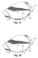
- An alternate finished molded end portion 226, shown in Figures 7A and 7B includes fabric or material end portion 222 integrated into the plastic material 224 in a web along portions of the width of molded end 226.
- End portion 226 illustrates a plurality of plastic tab portions with slight spacings between them.
- the impregnated and integrated fabric end portion 222 may be visible along portions of the top or bottom of the finished molded end portion 226 depending on how the fabric floats in the mold.
- Molded end 226 includes molded eyelets 228 formed by the locations of stakes 114 in the mold.
- the web or tab portions are typically adjacent and surrounding the pass-through members in the mold, such as stakes 114, and thus adjacent the resulting eyelets.
- the spaced tab portions preferably minimize puckering between the fabric and the finished end portion.
- a molded end portion or edge is shown for illustration in the present embodiment.
- other portions of the material may be placed in a mold for a particular use, and the mold cavity may be shaped as desired.
- a middle portion of the material can be placed in the molding cavity, with material portions extending beyond and clamped between the inner peripheries and the outer peripheries of the upper and lower mold portions.
- multiple ends, multiple sides or edges and/or substantially the entire periphery of a material piece can be integrated into one or more finished portions. Multiple portions may be molded simultaneously or separately.
- Figures 5A-D and 6 illustrate a cot made using the present invention.
- U.S. Patent Application Serial No. 60/496,534 filed on August 20, 2003 U.S. Patent Application Serial No. 60/541,084 filed on February 2,2004 and U.S. Patent Application Serial No. 10/910,758 filed on August 3, 2004 all entitled STACKABLE COT ASSEMBLY WITH ATTACHED END PIECES, describe in detail certain cot assemblies in which the present invention can be used.
- the present invention provides a cot assembly 10 ( FIG. 6 ).
- the cot includes a bedding material or fabric 20 that spans the entire interior of the cot frame, preferably without any gaps being present between the bedding material and the frame.
- the bedding material 20 and side frame portions are mounted to and supported by two end pieces 30 which securely and safely receive and hold the side frame portions and material.
- the side frame portions and ends form a perimeter which defines an interior area with fabric 20 in which a person lying on the cot is supported.
- a cot is flat and rectangular, although other geometric shapes may be used.
- a cot 10 having two side frame pieces and two end pieces 30.
- Permeable bedding material or fabric 20 has end edges connected to end pieces 30 and includes sleeves 24 on the side edges to receive the side frame pieces.
- Fabric 20 extends in the interior area to create a support surface for a person lying on the cot.
- the bedding fabric 20 extends horizontally substantially parallel to the floor, ground or support surface.
- the bedding fabric 20 is made from a material of suitable strength and comfort to support a person lying on the cot 10, the selection of which is within the ordinary skill in the art.
- Bedding fabric is typically a relatively thin, flexible and compliant material, preferably sheet-like in shape.
- the permeable bedding material may be any suitable one, e.g., a natural or synthetic sheeting, fabric, mat, webbing or the like.
- the material may be woven.
- the material has a higher melting point than the heated mold temperature and the temperature of the liquid plastic and is compatible to be impregnated or permeated with liquid plastic during the injection process.
- end piece 30 is shown upside down in FIGS. 5A-C , the opposing end piece is symmetric.
- end piece 30 includes one or more securing members, such as protruding stakes 35 along the inner periphery (for example, nine stakes are shown).
- the finished end portion 26 has molded eyelets 28, which are aligned with and placed over stakes 35 of end piece 30 ( FIG 5B ).
- the ends of stakes 35 are then heated and melted, bent, placed under pressure or otherwise deformed to form a plug to lock end portion 26 in place and thus retain material 20 to end piece 30 ( FIG. 5C ).
- this method of construction permanently connects material 20 to each end piece 30.
- a securing piece 38 having stake holes 39, is aligned and placed over stakes 35, over the molded end portion 26 and molded eyelets 28, so that stakes 35 extend all or partially through stake holes 39 and securing piece 38.
- the stakes are then heated and melted, bent, placed under pressure or otherwise deformed to form a plug to locking securing piece 38 in place, sandwiching end portion 26 between cot end piece 30 and securing piece 38.
- securing piece 38 can be a strip of plastic or metal.
- Stakes 35 are formed integrally with end pieces 30.
- End piece 30 may be made from a variety of materials, as would be understood by those of skill in the art. Examples include plastic, metal. Preferably end pieces 30 are cast or injection molded plastic.
- a finished cot is shown in Fig. 6 .
- no gaps are formed between fabric 20 and the end pieces 30.
- the term "gap free" or similar terms are used to describe the fact that the bedding material fills the interior of the area defined by the frame perimeter and the end pieces when viewed in the plan view.
- a preferred feature of the present invention is the provision of a gap free condition that is maintained while the bedding material is stretched during use.
- fabric 20 has a continuous or substantially distributed interface between the fabric and the end piece, minimizing potential point failure sources.
- the molded end portion contour matches the desired end piece connection portion.
- an even distribution of material i.e. unwrinkled
- the interface is illustrated herein as flat; however, alternate patterns can be used as desired. Examples of alternate interfaces include horizontal or vertical curves, corrugations, zig-zags or gathered portions.
Landscapes
- Engineering & Computer Science (AREA)
- Manufacturing & Machinery (AREA)
- Mechanical Engineering (AREA)
- Injection Moulding Of Plastics Or The Like (AREA)
Abstract
Description
- The present application claims priority to provisional application Serial No.
60/541,133, filed February 2, 2004 - The present invention relates generally to plastic injection molding, and more particularly to a method of injection molding incorporating a fabric into a plastic molded cot assembly.
- The general method of plastic injection molding is well known, including using a heated and sealed mold into which a liquid plastic material is introduced and then cured into a desired shape. Molded products have many material strengths. However, one drawback to traditional injection molding is the weakness inherent in an assembled article when the molded product transitions to a non-molded material, such as a fabric. Generally, a separate fastener mechanism has been required to attach the molded portion to a fabric, creating a potential point failure source between the fabric material and the plastic molded portion.
- One example is demonstrated in a cot assembly. In one typical cot, it is desired to attach the soft, middle portion, such as a woven material to a plastic molded end cap. Traditionally, this has required separate fasteners, such as posts, clips or brackets. However, when the fabric is placed under stress, for example by a person lying on the cot, the fabric tends to "pull away" from the fastener, and potentially tears or unravels, leading to a connection, failure.
-
US-A-2003/0137179 describes a method for attaching a load bearing fabric to a support structure including the steps of pluring the fabric in a mold and molding the carrier in situ about the fabric. - There has been a long-felt need in the industry for an improved fabric to plastic interface; however, previous efforts to solve this problem have been unsuccessful and have created skepticism in the industry. A need remains for an improved method to form integrated fabric and plastic molded products.
- The present invention satisfies these needs, among others.
- The invention is defined by the features of claim 1.
- The cot includes a perimeter structure and a fabric middle portion, where one or two of the fabric ends are cured within plastic portions to form integrated edge pieces, such that each edge piece is easily connectable to the cot structure. The finished edge pieces spread the interface tension between the fabric and plastic portion substantially along the width of the edge piece.
- Objects and advantages of the present invention will be apparent from the following description of the preferred embodiments.
-
-
FIG. 1 is a perspective view of a lower mold portion according to a preferred embodiment of the present invention. -
FIG. 2 is a perspective view of an upper mold portion according to a preferred embodiment of the present invention. -
FIG. 3 is a perspective view of a lower mold portion ofFig. 1 with a fabric material in place. -
FIGS. 4A and 4B illustrate top and bottom views of a molded end portion according to a preferred embodiment of the present invention. -
FIGS. 5A-5D illustrate molded end piece assembly methods for a cot. -
FIG. 6 is a perspective view of a cot assembly made according to one preferred embodiment of the present invention. -
FIGS. 7A and 7B illustrate top and bottom views of a molded end portion according to an alternate preferred embodiment of the present invention. - For the purposes of promoting an understanding of the principles of the invention, reference will now be made to the embodiments illustrated in the drawings and specific language will be used to describe the same. It will nevertheless be understood that no limitation of the scope of the invention is thereby intended, such alterations and further modifications in the illustrated device, and such further applications of the principles of the invention as illustrated therein being contemplated as would normally occur to one skilled in the art to which the invention relates.
- Certain embodiments of the present invention provide an improved method for manufacturing injection plastic molded cot assembly.
- The cot includes a perimeter structure and a fabric middle portion, where one, two or more of the fabric edges or ends are cured within plastic portions to form integrated end pieces, such that each end piece is easily connectable to the cot structure or frame. The finished piece preferably spreads the interface tension between the fabric and plastic portion, for example substantially along the width of an edge.
- A mold for use in the present invention and a method are illustrated in
Figures 1-3 . Mold 100 includes alower portion 110 and anupper portion 120.Lower portion 110 defines a moldinglower cavity 112, having an height and width, illustrated as extending substantially the horizontal length oflower portion 110. The lower cavity is defined between aninner periphery 116 and anouter periphery 118. Thelower cavity 112 may have a substantially constant width along its length. One or more pass-through members, such asplacement stakes 114 extend upward withinlower cavity 112. -
Upper mold portion 120 defines anupper mold cavity 122, having an height and width, illustrated as extending substantially the horizontal length ofupper portion 120. The upper cavity is defined between aninner periphery 126 and anouter periphery 128. Preferably theupper cavity 122 is symmetric to the lower cavity. One or more stake holes orrecesses 124 are defined inupper cavity 122.Lower portion 110 and/orupper portion 120 define one ormore injection ports 115 and/or 125 in fluid communication with the mold cavity.Lower cavity 112 andupper cavity 122 may have smooth or textured surfaces as desired, for example, a texture of a grid pattern to enhance gripping and traction. -
Lower portion 110 andupper portion 120 are made in matched sizes to be closed asmold 100. When the mold portions are closed,lower cavity 112 andupper cavity 122 form an enclosed cavity defining the size and shape of the intended injection molded product. When closed,outer peripheries inner peripheries more stakes 114 extend through the enclosed cavity and the upper ends are received inmatching recesses 124.Lower portion 110 andupper portion 120 may have posts, ridges, channels, recesses or similar indicia to allow the mold to align and close properly. - Mold 100 is formed of known materials for an injection mold, typically steel or a similar metal. The mold clamping portions are preferably suitable to be placed under pressure and heated while a liquid plastic material is injected into the enclosed cavity and then cured by holding and cooling. A conventional injector or injectors are used.
- When used in accordance with the present invention, a fabric-type
permeable material 20 is placed overlower mold portion 110 with a portion, such asend edge 22, aligned with and typically withinlower cavity 112. In a preferred feature, openings, such as eyelets 25, defined in thematerial 20 are placed over pass-through members, such asstakes 114. Preferably in the present embodiment, the material is aligned to be substantially flat over theinner periphery 116, forming a continuous and uniform interface, without wrinkles. - The
mold 100 is then closed and clamped or placed under pressure, withupper portion 120 engaginglower portion 110. Preferably, the inner peripheries of the mold portions are substantially sealed closely adjacent each other with pressure, while thematerial 20 remains substantially flat between them. A liquid plastic is then injected under pressure into the upper and lower cavity in the mold and air is removed or allowed to escape. Preferably, liquid plastic is injected in the upper and lower cavities simultaneously. Preferably, thefabric end 22 in the cavity "floats" in the injected material as the cavity is filled and the liquid plastic permeates the fabric material. In certain embodiments, the liquid plastic includes portions at least partially above and below the fabric material with a plastic matrix communicating or passing through the material. The plastic material is then cooled/cured, substantially embedding and locking the fabric material in a plastic matrix. When ready, the mold is opened and the finished moldedend 26 is removed. - As an example, some mold operation parameters are provided. These parameters can be varied by those of skill in the art while the process is still within the scope of the present invention. For example, the mold may have a clamping pressure or 61 kg/cm2 and operate at a temperature of 205 degrees Centigrade. In use, the liquid plastic is injected in a 6 second cycle and the pressure is held stable for approximately 1.5 seconds while the plastic settles. The mold then has a cooling time of 13 seconds before the part is ejected. One example plastic material is a Polypropylene - PP Copolymer. In this arrangement, the overall cycle time is approximately one minute. An example mold size is 55 cm x 28cm x 18.2cm. Other examples of plastic molding materials include polymer materials such as polyamide, polyacetal, polyvinylchloride, polyethelene, polycarbonate or a Nylon® material. Preferably, the plastic in a liquid state is of low enough viscosity to permeate through the fabric material.
- Preferably a woven style fabric material is used. In one preferred embodiment, the fabric in formed from a woven mesh of polyester yarns which are coated with vinyl prior to weaving. Portions of the fabric may optionally be bonded or sealed with heat. The woven mesh is preferably in a range of 4 X 4 to 30 X 30 threads per square inch, with one preferred weave of 15 threads per inch by 13 double threads per inch.
- In certain embodiments, the fabric is formed of threads of a Nylon® material, cloth or other natural, synthetic or plastic materials. The material preferably bonds or interacts well with the liquid plastic during injection and as a finished piece. Preferably the fabric material is selected to not melt, disfigure or lose strength when subjected to the mold pressure and temperature. In one option, one or more openings such as holes are defined or punched through the material to allow injected liquid plastic to flow or permeate through the openings, facilitating the bonding of the plastic to the material and bonding between upper and lower plastic portions.
- Finished molded
end portion 26, shown inFigures 4A and 4B , includes fabric ormaterial end portion 22 continuously integrated into theplastic material 23 in a web along the width of moldedend 26. Due to floating, pieces of theend portion 22 of the permeable material are typically at various heights in the cross-section of the plastic 23 along the width of moldedend 26. As shown inFIGS. 4A and 4B , the impregnated and integratedfabric end portion 22 may be visible along portions of the top or bottom of the finished moldedend portion 26 depending on how the fabric floats in the mold. As an optional feature in the preferred embodiment illustrated, moldedend 26 includes moldedeyelets 28 formed by the locations ofstakes 114 in the mold. - An alternate finished molded
end portion 226, shown inFigures 7A and 7B , includes fabric ormaterial end portion 222 integrated into theplastic material 224 in a web along portions of the width of moldedend 226.End portion 226 illustrates a plurality of plastic tab portions with slight spacings between them. As shown inFIGS. 4A and 4B , the impregnated and integratedfabric end portion 222 may be visible along portions of the top or bottom of the finished moldedend portion 226 depending on how the fabric floats in the mold. Moldedend 226 includes moldedeyelets 228 formed by the locations ofstakes 114 in the mold. The web or tab portions are typically adjacent and surrounding the pass-through members in the mold, such asstakes 114, and thus adjacent the resulting eyelets. The spaced tab portions preferably minimize puckering between the fabric and the finished end portion. - A molded end portion or edge is shown for illustration in the present embodiment. As desired, other portions of the material may be placed in a mold for a particular use, and the mold cavity may be shaped as desired. As one example, a middle portion of the material can be placed in the molding cavity, with material portions extending beyond and clamped between the inner peripheries and the outer peripheries of the upper and lower mold portions. As another example, multiple ends, multiple sides or edges and/or substantially the entire periphery of a material piece can be integrated into one or more finished portions. Multiple portions may be molded simultaneously or separately.
-
Figures 5A-D and6 illustrate a cot made using the present invention.U.S. Patent Application Serial No. 60/496,534 filed on August 20, 2003 U.S. Patent Application Serial No. 60/541,084 filed on February 2,2004 U.S. Patent Application Serial No. 10/910,758 filed on August 3, 2004 - The present invention provides a cot assembly 10 (
FIG. 6 ). The cot includes a bedding material orfabric 20 that spans the entire interior of the cot frame, preferably without any gaps being present between the bedding material and the frame. Thebedding material 20 and side frame portions are mounted to and supported by twoend pieces 30 which securely and safely receive and hold the side frame portions and material. The side frame portions and ends form a perimeter which defines an interior area withfabric 20 in which a person lying on the cot is supported. Traditionally a cot is flat and rectangular, although other geometric shapes may be used. - Referring in particular to
FIGS. 5A-C and6 , there is shown acot 10 having two side frame pieces and twoend pieces 30. Permeable bedding material orfabric 20 has end edges connected to endpieces 30 and includessleeves 24 on the side edges to receive the side frame pieces.Fabric 20 extends in the interior area to create a support surface for a person lying on the cot. Thebedding fabric 20 extends horizontally substantially parallel to the floor, ground or support surface. Thebedding fabric 20 is made from a material of suitable strength and comfort to support a person lying on thecot 10, the selection of which is within the ordinary skill in the art. Bedding fabric is typically a relatively thin, flexible and compliant material, preferably sheet-like in shape. The permeable bedding material may be any suitable one, e.g., a natural or synthetic sheeting, fabric, mat, webbing or the like. The material may be woven. Preferably the material has a higher melting point than the heated mold temperature and the temperature of the liquid plastic and is compatible to be impregnated or permeated with liquid plastic during the injection process. - An
end piece 30 is shown upside down inFIGS. 5A-C , the opposing end piece is symmetric. As illustrated,end piece 30 includes one or more securing members, such as protrudingstakes 35 along the inner periphery (for example, nine stakes are shown). For one method of assembly, shown inFIGS. 5A-C , thefinished end portion 26, has moldedeyelets 28, which are aligned with and placed overstakes 35 of end piece 30 (FIG 5B ). The ends ofstakes 35 are then heated and melted, bent, placed under pressure or otherwise deformed to form a plug to lockend portion 26 in place and thus retainmaterial 20 to end piece 30 (FIG. 5C ). Preferably this method of construction permanently connectsmaterial 20 to eachend piece 30. - In an alternate assembly method, shown in
FIG. 5D , a securingpiece 38, having stake holes 39, is aligned and placed overstakes 35, over the moldedend portion 26 and moldedeyelets 28, so thatstakes 35 extend all or partially through stake holes 39 and securingpiece 38. The stakes are then heated and melted, bent, placed under pressure or otherwise deformed to form a plug to locking securingpiece 38 in place, sandwichingend portion 26 betweencot end piece 30 and securingpiece 38. As examples, securingpiece 38 can be a strip of plastic or metal. -
Stakes 35 are formed integrally withend pieces 30. -
End piece 30 may be made from a variety of materials, as would be understood by those of skill in the art. Examples include plastic, metal. Preferably endpieces 30 are cast or injection molded plastic. - An illustration of a finished cot is shown in
Fig. 6 . Preferably no gaps are formed betweenfabric 20 and theend pieces 30. As used herein, the term "gap free" or similar terms are used to describe the fact that the bedding material fills the interior of the area defined by the frame perimeter and the end pieces when viewed in the plan view. Moreover, a preferred feature of the present invention is the provision of a gap free condition that is maintained while the bedding material is stretched during use. - Also preferably,
fabric 20 has a continuous or substantially distributed interface between the fabric and the end piece, minimizing potential point failure sources. Preferably, the molded end portion contour matches the desired end piece connection portion. Typically, an even distribution of material (i.e. unwrinkled) minimizes stresses compared to gathers or uneven stretching. The interface is illustrated herein as flat; however, alternate patterns can be used as desired. Examples of alternate interfaces include horizontal or vertical curves, corrugations, zig-zags or gathered portions. - While the invention has been illustrated and described in detail in the drawings and foregoing description, the same is to be considered as illustrative and not restrictive in character, it being understood that only the preferred embodiment has been shown and described and that all changes and modifications that come within the scope of the claims that follow are desired to be protected.
Claims (13)
- A method, comprising:providing a permeable cot bedding material (20);aligning an edge portion (22) of said permeable material (20) in a plastic Injection mold (100) with a mold cavity (112, 122), said mold cavity having a plurality of pass-through members (114) to pass through said permeable material (20);closing said mold (100) to substantially seal said material edge portion (22) in said mold cavity (112, 122);injecting a liquid plastic material into said mold cavity (112, 122), wherein said liquid plastic permeates said material edge portion (22);curing said liquid plastic material to embed said material edge portion (22) within a plastic portion to form a finished portion (26), said pass through members (114) defining a plurality of pass-through openings (28) in said finished portion (26);securing said finished portion (26) with said material edge portion (22) embedded within a plastic portion to a cot end piece (30), said cot end piece (30) having at least one support for supporting said bedding material (20) above a support surface; wherebythe securing comprises aligning pass-through openings (28) defined in said finished portion (26) over securing members (35) on said cot end piece (30), the securing members (35) formed integrally with said cot end piece, and deforming said securing members (35) with heat to secure said finished portion (26) to said cot end piece (30).
- The method of claim 1, wherein said aligning comprises placing said permeable material portion (20) substantially evenly in said mold cavity (112, 122).
- The method of claim 2, wherein said aligning comprises placing said permeable material portion (20) substantially flat in said mold cavity (112, 122).
- The method of claim 2, wherein said aligning comprises placing openings defined in said permeable material portion (20) over a plurality of pass-through members (114) in said mold cavity (112, 122).
- The method of claim 4, wherein said finished portion (26) comprises a plurality of spaced plastic and material permeated portions correspondingly adjacent said plurality of pass-through members (35).
- The method of claim 4, wherein said finished portion (26) forms a substantially continuous web across an edge of said permeable material portion.
- The method of claim 1, comprising heating said plastic material to a liquid state, and wherein said permeable material portion (20) has a melting point greater than the temperature of said liquid plastic material in said liquid state.
- The method of claim 1, wherein said permeable material portion (20) is woven.
- The method of claim 8, wherein said permeable material portion (20) is synthetic.
- The method of claim 1, comprising floating said permeable material portion (20) in said mold cavity (112, 122) while injecting said liquid plastic material.
- The method of claim 1, comprising arranging a securing piece (38) over said securing members (35) to sandwich said finished portion (26) between said cot end piece (30) and said securing piece (38).
- The method of claim 1, comprising securing a second edge portion of said permeable material (20) to embed said second edge portion within a plastic portion to form a second finished portion and securing said second finished end portion to a second cot end piece.
- The method of claim 12, wherein said two edge portions are permeated with plastic substantially along the width of said edges.
Applications Claiming Priority (3)
| Application Number | Priority Date | Filing Date | Title |
|---|---|---|---|
| US54113304P | 2004-02-02 | 2004-02-02 | |
| US11/030,426 US20050166317A1 (en) | 2004-02-02 | 2005-01-05 | Method of manufacture and products using fabric in injection molding |
| PCT/US2005/002651 WO2005074533A2 (en) | 2004-02-02 | 2005-02-02 | Method of manufacture and products using fabric in injection molding |
Publications (3)
| Publication Number | Publication Date |
|---|---|
| EP1727447A2 EP1727447A2 (en) | 2006-12-06 |
| EP1727447A4 EP1727447A4 (en) | 2008-06-04 |
| EP1727447B1 true EP1727447B1 (en) | 2011-11-30 |
Family
ID=34810447
Family Applications (1)
| Application Number | Title | Priority Date | Filing Date |
|---|---|---|---|
| EP05706123A Expired - Lifetime EP1727447B1 (en) | 2004-02-02 | 2005-02-02 | Method for manufacturing a cot |
Country Status (3)
| Country | Link |
|---|---|
| US (1) | US20050166317A1 (en) |
| EP (1) | EP1727447B1 (en) |
| WO (1) | WO2005074533A2 (en) |
Families Citing this family (13)
| Publication number | Priority date | Publication date | Assignee | Title |
|---|---|---|---|---|
| US7111551B2 (en) * | 2004-07-16 | 2006-09-26 | Bruce Arlen Borgen | Method and system for manufacturing a screen printing frame holding a screen using curable resin |
| US9598782B2 (en) | 2008-04-11 | 2017-03-21 | Christopher M. McWhinney | Membrane module |
| DE102008049393A1 (en) * | 2008-09-27 | 2010-04-08 | Intier Automotive Eybl Interiors Gmbh | A method of manufacturing an injection molded part having a fastener insert embedded therein |
| EP2787862B1 (en) | 2011-12-08 | 2017-06-07 | Herman Miller, Inc. | Composite body support member and methods for the manufacture and recycling thereof |
| USD703457S1 (en) | 2013-06-07 | 2014-04-29 | Herman Miller, Inc. | Chair |
| USD747116S1 (en) | 2014-07-21 | 2016-01-12 | Foundations Worldwide, Inc. | Cot |
| US9398815B2 (en) | 2014-07-21 | 2016-07-26 | Foundations Worldwide, Inc. | Cot |
| US10045629B2 (en) * | 2014-10-14 | 2018-08-14 | Wood Designs | Stackable leg |
| US10150236B2 (en) * | 2014-11-01 | 2018-12-11 | Mann+Hummel Gmbh | Method of positioning and holding an air permeable media within a mold prior to closure and through encapsulation, and an overmolded HCA trap produced by the method |
| CA2918754C (en) * | 2015-01-26 | 2019-03-12 | Christopher M. Mcwhinney | Membrane module |
| ES2757724T3 (en) * | 2016-10-14 | 2020-04-30 | Cooper Standard GmbH | Window Guide Channel Assembly Forming Procedure |
| CA2960350C (en) * | 2017-03-09 | 2024-05-21 | BATRIK Medical Manufacturing Inc. | Step stool with anti-microbial protection |
| US10477972B2 (en) * | 2018-03-24 | 2019-11-19 | Dongguan Kentec Office Seating Co., Ltd. | Assembling structure of support device of a chair |
Family Cites Families (19)
| Publication number | Priority date | Publication date | Assignee | Title |
|---|---|---|---|---|
| US2124643A (en) * | 1937-05-03 | 1938-07-26 | Walger William | Cot structure |
| US3087201A (en) * | 1960-03-02 | 1963-04-30 | Us Rubber Co | Method of injection molding fabricreinforced articles |
| DE2951329C2 (en) * | 1979-12-20 | 1982-11-11 | Brokmann, Manfred, Ing. (Grad.) | Belts, in particular seat belts for furniture |
| US4299645A (en) * | 1980-05-30 | 1981-11-10 | Newsom Charles R | Method for assembling fabric to an article of furniture |
| US4793008A (en) * | 1986-02-18 | 1988-12-27 | Johansson Paul J | Method of transferring a patient and mats therefor |
| US5003649A (en) * | 1990-01-05 | 1991-04-02 | Angeles Nursery Toys, Inc. | Nestable cot and end connector therefor |
| USD328401S (en) * | 1990-02-14 | 1992-08-04 | Angeles Nursery Toys, Inc. | Combined end connector and pedestal for nestable cot or the like |
| US5263424A (en) * | 1990-12-28 | 1993-11-23 | Angeles Group, Inc. | Utility/activity structure and activity board therefor |
| US5568662A (en) * | 1994-04-08 | 1996-10-29 | Gougelet; Robert M. | Spinal/cervical immobilization device and method |
| US5527500A (en) * | 1994-06-02 | 1996-06-18 | The Tensar Corporation | Method of forming a framed panel utilizing tensioning by heat shrinking |
| US6345400B2 (en) * | 1999-04-26 | 2002-02-12 | Earlychildhood Llc | Portable cot apparatus |
| JP2001224461A (en) * | 1999-12-07 | 2001-08-21 | Takano Co Ltd | Chair |
| US6513178B1 (en) * | 2000-05-15 | 2003-02-04 | Agi, Llc | Cot assembly |
| DE10037728C1 (en) * | 2000-08-02 | 2002-02-21 | Adidas Int Bv | Shoe, in particular running shoe and process for its manufacture |
| US6511562B1 (en) * | 2000-09-06 | 2003-01-28 | Dahti, Inc. | Bonding strip for load bearing fabric |
| US6540950B1 (en) * | 2000-09-20 | 2003-04-01 | Dahti, Inc. | Carrier and attachment method for load bearing fabric |
| US6842959B2 (en) * | 2001-01-25 | 2005-01-18 | Dahti, Inc. | Load bearing fabric attachment and associated method |
| JP2002276889A (en) * | 2001-03-14 | 2002-09-25 | Mitsuboshi Co Ltd | Flat face structure, and manufacturing method and device thereof |
| US6564400B2 (en) * | 2001-10-19 | 2003-05-20 | Agi, Llc | Continuous tube cot assembly |
-
2005
- 2005-01-05 US US11/030,426 patent/US20050166317A1/en not_active Abandoned
- 2005-02-02 EP EP05706123A patent/EP1727447B1/en not_active Expired - Lifetime
- 2005-02-02 WO PCT/US2005/002651 patent/WO2005074533A2/en not_active Ceased
Also Published As
| Publication number | Publication date |
|---|---|
| EP1727447A4 (en) | 2008-06-04 |
| EP1727447A2 (en) | 2006-12-06 |
| US20050166317A1 (en) | 2005-08-04 |
| WO2005074533A2 (en) | 2005-08-18 |
| WO2005074533A3 (en) | 2007-01-04 |
Similar Documents
| Publication | Publication Date | Title |
|---|---|---|
| US20050166317A1 (en) | Method of manufacture and products using fabric in injection molding | |
| US7488527B2 (en) | Molded touch fasteners | |
| CN104223607B (en) | Clip type fastener zipper with anti-seepage structure | |
| ES2291509T3 (en) | LOOP MATERIALS FOR CLOSURE BY CONTACT. | |
| CN103079422B (en) | Forming surface zipper | |
| CN102202539B (en) | Molding male surface fastener | |
| US7678318B2 (en) | Touch fastener products | |
| EP0805064A2 (en) | Seat cushion and method of molding a seat unit including the seat cushion | |
| US20020023322A1 (en) | Surface fastener | |
| EP0266742A2 (en) | Method of molding a composite article | |
| GB2337019B (en) | Improved filtering screen and support frame therefor | |
| EP1348530B1 (en) | Fastening member and process for producing molded resin article having the same | |
| JP2007530189A (en) | Hook fastener parts | |
| KR100522274B1 (en) | Connected fastening members and process for production of resin molded article with fastening member | |
| US20010046424A1 (en) | Methods for making tie down anchor devices and products thereof | |
| US20030084553A1 (en) | Hook engageable loops | |
| JP3666559B2 (en) | Seat body in chair and the like and method for manufacturing the same | |
| CN104757749A (en) | Forming surface zipper | |
| WO1985003625A1 (en) | Separable fastener | |
| US4271630A (en) | Soil supports for plant containers | |
| KR900007323B1 (en) | Manufacture of molded product with engagement member | |
| US20060192420A1 (en) | Furniture item and a method for attaching webbing thereto | |
| CA1110070A (en) | Soil supports for plant containers | |
| JP3137587U (en) | Shoe upper material using pleated fabric and shoes using the same | |
| US20010014380A1 (en) | Multilayer molded articles |
Legal Events
| Date | Code | Title | Description |
|---|---|---|---|
| PUAI | Public reference made under article 153(3) epc to a published international application that has entered the european phase |
Free format text: ORIGINAL CODE: 0009012 |
|
| 17P | Request for examination filed |
Effective date: 20060726 |
|
| AK | Designated contracting states |
Kind code of ref document: A2 Designated state(s): AT BE BG CH CY CZ DE DK EE ES FI FR GB GR HU IE IS IT LI LT LU MC NL PL PT RO SE SI SK TR |
|
| AX | Request for extension of the european patent |
Extension state: AL BA HR LV MK YU |
|
| PUAK | Availability of information related to the publication of the international search report |
Free format text: ORIGINAL CODE: 0009015 |
|
| DAX | Request for extension of the european patent (deleted) | ||
| RBV | Designated contracting states (corrected) |
Designated state(s): DE FR GB |
|
| A4 | Supplementary search report drawn up and despatched |
Effective date: 20080507 |
|
| 17Q | First examination report despatched |
Effective date: 20091113 |
|
| REG | Reference to a national code |
Ref country code: DE Ref legal event code: R079 Ref document number: 602005031446 Country of ref document: DE Free format text: PREVIOUS MAIN CLASS: A47C0017000000 Ipc: B29C0045140000 |
|
| GRAP | Despatch of communication of intention to grant a patent |
Free format text: ORIGINAL CODE: EPIDOSNIGR1 |
|
| RIC1 | Information provided on ipc code assigned before grant |
Ipc: B29C 45/14 20060101AFI20110331BHEP Ipc: A47D 13/06 20060101ALI20110331BHEP |
|
| RTI1 | Title (correction) |
Free format text: METHOD FOR MANUFACTURING A COT |
|
| GRAS | Grant fee paid |
Free format text: ORIGINAL CODE: EPIDOSNIGR3 |
|
| GRAA | (expected) grant |
Free format text: ORIGINAL CODE: 0009210 |
|
| AK | Designated contracting states |
Kind code of ref document: B1 Designated state(s): DE FR GB |
|
| REG | Reference to a national code |
Ref country code: GB Ref legal event code: FG4D |
|
| REG | Reference to a national code |
Ref country code: DE Ref legal event code: R096 Ref document number: 602005031446 Country of ref document: DE Effective date: 20120301 |
|
| PLBE | No opposition filed within time limit |
Free format text: ORIGINAL CODE: 0009261 |
|
| STAA | Information on the status of an ep patent application or granted ep patent |
Free format text: STATUS: NO OPPOSITION FILED WITHIN TIME LIMIT |
|
| 26N | No opposition filed |
Effective date: 20120831 |
|
| REG | Reference to a national code |
Ref country code: DE Ref legal event code: R097 Ref document number: 602005031446 Country of ref document: DE Effective date: 20120831 |
|
| REG | Reference to a national code |
Ref country code: FR Ref legal event code: PLFP Year of fee payment: 12 |
|
| REG | Reference to a national code |
Ref country code: FR Ref legal event code: PLFP Year of fee payment: 13 |
|
| REG | Reference to a national code |
Ref country code: FR Ref legal event code: PLFP Year of fee payment: 14 |
|
| PGFP | Annual fee paid to national office [announced via postgrant information from national office to epo] |
Ref country code: DE Payment date: 20240304 Year of fee payment: 20 Ref country code: GB Payment date: 20240229 Year of fee payment: 20 |
|
| PGFP | Annual fee paid to national office [announced via postgrant information from national office to epo] |
Ref country code: FR Payment date: 20240228 Year of fee payment: 20 |
|
| REG | Reference to a national code |
Ref country code: DE Ref legal event code: R071 Ref document number: 602005031446 Country of ref document: DE |
|
| REG | Reference to a national code |
Ref country code: GB Ref legal event code: PE20 Expiry date: 20250201 |
|
| PG25 | Lapsed in a contracting state [announced via postgrant information from national office to epo] |
Ref country code: GB Free format text: LAPSE BECAUSE OF EXPIRATION OF PROTECTION Effective date: 20250201 |