EP1727258A2 - Stator and method of forming the same - Google Patents
Stator and method of forming the same Download PDFInfo
- Publication number
- EP1727258A2 EP1727258A2 EP06010496A EP06010496A EP1727258A2 EP 1727258 A2 EP1727258 A2 EP 1727258A2 EP 06010496 A EP06010496 A EP 06010496A EP 06010496 A EP06010496 A EP 06010496A EP 1727258 A2 EP1727258 A2 EP 1727258A2
- Authority
- EP
- European Patent Office
- Prior art keywords
- core
- stator
- slot
- groove
- forming
- Prior art date
- Legal status (The legal status is an assumption and is not a legal conclusion. Google has not performed a legal analysis and makes no representation as to the accuracy of the status listed.)
- Withdrawn
Links
Images



Classifications
-
- H—ELECTRICITY
- H02—GENERATION; CONVERSION OR DISTRIBUTION OF ELECTRIC POWER
- H02K—DYNAMO-ELECTRIC MACHINES
- H02K1/00—Details of the magnetic circuit
- H02K1/06—Details of the magnetic circuit characterised by the shape, form or construction
- H02K1/12—Stationary parts of the magnetic circuit
- H02K1/16—Stator cores with slots for windings
-
- H—ELECTRICITY
- H02—GENERATION; CONVERSION OR DISTRIBUTION OF ELECTRIC POWER
- H02K—DYNAMO-ELECTRIC MACHINES
- H02K15/00—Processes or apparatus specially adapted for manufacturing, assembling, maintaining or repairing of dynamo-electric machines
- H02K15/02—Processes or apparatus specially adapted for manufacturing, assembling, maintaining or repairing of dynamo-electric machines of stator or rotor bodies
- H02K15/021—Magnetic cores
-
- H—ELECTRICITY
- H02—GENERATION; CONVERSION OR DISTRIBUTION OF ELECTRIC POWER
- H02K—DYNAMO-ELECTRIC MACHINES
- H02K15/00—Processes or apparatus specially adapted for manufacturing, assembling, maintaining or repairing of dynamo-electric machines
- H02K15/06—Embedding prefabricated windings in the machines
-
- H—ELECTRICITY
- H02—GENERATION; CONVERSION OR DISTRIBUTION OF ELECTRIC POWER
- H02K—DYNAMO-ELECTRIC MACHINES
- H02K2201/00—Specific aspects not provided for in the other groups of this subclass relating to the magnetic circuits
- H02K2201/06—Magnetic cores, or permanent magnets characterised by their skew
Definitions
- the present invention relates to a stator and a method of forming the stator.
- a conventional stator for use in an electric motor and a method of forming the stator are disclosed by Japanese Unexamined Patent Application Publication (KOKAI) No. 2001-8417 wherein a plurality of core sheets having holes with concentric circles are stacked to form a stator core.
- Each core sheet has a plurality of recesses formed in the inner edge thereof thereby to form a plurality of slots in the inner circumferential surface of the stator core.
- the slots are in parallel with an axis of the stator core, in which a coil is inserted.
- Each core sheet also has a plurality of recesses formed in the outer edge thereof thereby to form a plurality of engaging grooves in the outer circumferential surface of the stator core.
- the engaging grooves are in parallel with the axis of the stator core, with which an engaging tool is engaged for skewing the slots.
- the outer circumferential surface of the stator core is a cylindrical surface
- the outer circumferential surface of the stator core is formed with fixation grooves for fixing the core sheets and alignment grooves for mounting the stator core on a housing of the electric motor as well as the engaging grooves with which the tool is engaged.
- fixation grooves for fixing the core sheets
- alignment grooves for mounting the stator core on a housing of the electric motor as well as the engaging grooves with which the tool is engaged.
- the present invention is directed to a stator of which fixed cost of a stator core and accuracy of skew angle of slots of the stator core are improved and a method of forming the stator.
- the stator includes a cylindrical stator core and a coil.
- the stator core is formed by stacking a plurality of core sheets.
- the stator core has a groove formed in an outer circumferential surface thereof and a slot.
- the coil is inserted in the slot.
- the groove is located parallel to an axis of the stator core and the slot is skewed with respect to the axis.
- the stator has a cylindrical stator core and a coil.
- the stator core is formed by stacking a plurality of core sheets.
- the stator core has a groove formed in an outer circumferential surface thereof and a slot in which the coil is inserted.
- the method including the steps of: forming the core sheets each having a slot opening for forming the slot and a recess for forming the groove, in which the corresponding recesses of the core sheets for forming the same groove are stepwise shifted from each other by a predetermined angle with respect to the slot opening; stacking the core sheets so that the slot is located parallel to an axis of the stator core; inserting the coil into the slot; skewing the slot by rotating the core sheets so that the groove is located parallel to the axis of the stator core; and welding the core sheets using the groove to fix the core sheets.
- the stator has a cylindrical stator core and a coil.
- the stator core is formed by stacking a plurality of core sheets.
- the stator core has a groove formed in an outer circumferential surface thereof and a slot in which the coil is inserted.
- the method including the steps of: forming the core sheets each having a slot opening for forming the slot and a recess for forming the groove, in which the corresponding recesses of the core sheets for forming the same groove are stepwise shifted from each other by a predetermined angle with respect to the slot opening; stacking the core sheets so that the groove is located parallel to an axis of the stator core; welding the core sheets using the groove to fix the core sheets; and inserting the coil into the slot.
- FIG. 1 shows a stator core of a stator of the first embodiment.
- the stator core 1 is formed of a cylindrical shape and has a hollow portion 8 formed of a cylindrical shape.
- the stator core 1 is concentric with the hollow portion 8.
- An alternate long and short line shows an axis L of the stator core 1.
- the stator core 1 is so formed that a plurality of core sheets each of which has a disc-like shape are stacked. Three of the core sheets are shown in FIG. 2 and are identified by reference numbers 10, 10' and 10".
- the core sheet 10 is formed of a disc-like shape and has a hole 11 concentrically.
- the core sheet 10 has an inner edge 10a and an outer edge 10b thereof.
- a plurality of slot openings 15 are equally spaced in the inner edge 10a.
- Four recesses 12 are equally spaced in the outer edge 10b in the circumferential direction thereof.
- Adjacent recesses 12, 12 have a pair of recesses 13, 14 in the middle thereof, which are adjacent to each other, and therefore, four pairs of the recesses 13, 14 are formed in the outer edge 10b.
- the core sheet 10' is so formed that the positions of the slot openings 15 are not changed from those of the core sheet 10 and the positions of the recesses 12, 13 and 14 formed in the outer edge 10b are shifted from those of the core sheet 10 in the circumferential direction of the outer edge 10b by equidistance to form recesses 12', 13' and 14'.
- the core sheet 10" is so formed that the positions of the slot openings 15 are not changed from those of the core sheet 10' and the positions of the recesses 12', 13' and 14' are shifted from those of the core sheet 10' in the circumferential direction of the outer edge 10b by the same distance as the distance by which the positions of the recesses 12, 13 and 14 are shifted to those of the recesses 12', 13' and 14' to form recesses 12", 13" and 14".
- FIG. 2 there are actually number of core sheets needed for forming the stator core 1 (refer to FIG. 1).
- the positions of the corresponding recesses formed in the outer edges of the core sheets are stepwise shifted from each other in the circumferential direction of the outer edge by equidistance. That is, when the straight line which passes through the center O 10 of the core sheet 10 and the position of the recess 13 is identified by a reference number L 10 as shown in FIG. 2, the straight line L 10 , which passes through the center O 10' of the core sheet 10' and the position of the recess 13' and the straight line L 10" which passes through the center O 10" of the core sheet 10" and the position of the recess 13" are shifted from the straight line L 10 by angles of ⁇ and 2 ⁇ , respectively.
- the corresponding recesses formed in the outer edges of the core sheets for forming the same groove are stepwise shifted from each other with respect to the slot openings 15 formed in the inner edge of each core sheet by an angle of ⁇ . It is noted that for the sake of explanatory convenience, the angle ⁇ is more exaggeratedly shown in FIG. 2 than the actual angle.
- the above core sheets 10, 10', 10" and the like are stacked to form the stator core 1 as shown in FIG. 1.
- the outer circumferential surface of the stator core 1 is formed with four engaging grooves 2, four fixation grooves 3 and four alignment grooves 4.
- the recesses 12 and the corresponding recesses 12', 12" and the like are aligned with each other to form the four engaging grooves 2.
- the recesses 13 and the corresponding recesses 13', 13" and the like are aligned with each other to form the four fixation grooves 3.
- the recesses 14 and the corresponding recesses 14', 14" and the like are aligned with each other to form the four alignment grooves 4.
- An engaging tool (not shown) is engaged with one of the engaging grooves 2 for skewing the core sheets.
- the fixation grooves 3 are used for fixing the stacked core sheets by welding.
- the alignment grooves 4 are used for positioning the stator core 1 in mounting the stator core 1 on a housing of a motor (not shown).
- the grooves 2, 3 and 4 are in parallel with the axis L of the stator core 1.
- the inner circumferential surface of the stator core 1 is formed with a plurality of slots 6.
- the corresponding slot openings 15 of the core sheets are aligned with each other to form a plurality of slots 6.
- Each slot 6 is inclined or skewed at an angle (skew angle) with respect to the axis L.
- the inclination of the slot 6 results from the fact that the corresponding recesses of the core sheets for forming the same groove are stepwise shifted from each other by a predetermined angle with respect to the slot openings 15.
- the skew angle is adjustable by changing the angle ⁇ by which the corresponding recesses formed in the outer edges of the core sheets for forming the same groove are stepwise shifted from each other with respect to the slot openings 15 formed in the inner edges.
- a coil (not shown) is inserted into the slots 6 of the stator core 1 thereby to form the stator.
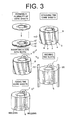
- a method of forming the stator according to the first embodiment will now be described with reference to FIG. 3.
- a plurality of core sheets 10', 10" and the like in which the corresponding recesses formed in the outer edges of the core sheets for forming the same groove are stepwise shifted from each other with respect to the slot openings 15 formed in the inner edges by a predetermined angle are pressed into shapes so as to be stacked.
- the core sheets are stacked so that the slots 6 which lie lengthwise in the inner circumferential surface of the core sheets are located parallel to the axis L.
- the grooves 2, 3 and 4 formed in the inner circumferential surface of the core sheets are equiangularly inclined with respect to the axis L.
- a coil 7 is inserted into the slots 6. Since the slots 6 are in parallel with the axis L, the coil 7 is inserted into the slots 6 in a normal manner. Subsequently, an engaging tool 20 is engaged with the engaging groove 2 for skewing the core sheets.
- the core sheets are rotated around the axis L by the engaging tool 20 so that the grooves 2 are located parallel to the axis L, that is, the grooves 3 and 4 which are in parallel with the groove 2 are also located parallel to the axis L.
- the slots 6 are skewed by the skew angle caused by the angle ⁇ by which the corresponding recesses for forming the same groove are shifted from each other with respect to the slot openings 15.
- the core sheets are welded and fixed so that padding is performed along the fixation groove 3, thereby to form the stator core.
- a plurality of core sheets are formed so as to stepwise shift the corresponding recesses formed in the outer edges of the core sheets for forming the same groove from each other with respect to the slot openings 15 formed in the inner edges by a predetermined angle, and the core sheets are stacked so that the slots 6 are located parallel to the axis L, and the coil 7 is inserted into the slots 6.
- the slots 6 are skewed so that the grooves 2, 3 and 4 are located parallel to the axis L. This causes the grooves 2, 3 and 4 to be aligned without wave, thereby to skew the slots 6 without wave. Therefore, accuracy of the skew angle of the slots 6 is improved.
- the skew angle of the slots 6 is easily controlled compared to the conventional case where the skew angle of the grooves of the outer peripheral surface of the stator core was measured. Furthermore, since the fixation grooves 3 are located parallel to the axis L, the torch is moved vertically upon welding, which prevents cost rise of welding equipment. Furthermore, since the alignment grooves 4 are located parallel to the axis L, a positioning pin can be easily inserted into the alignment groove 4 in mounting the stator on the motor housing (not shown), which improves positioning accuracy.
- a stator according to the second embodiment of the present invention will now be described. Since the same reference numerals of FIGs. 1 through 3 are substantially the same components in the second embodiment, detailed description thereof is omitted.
- a method of forming the stator according to the second embodiment is a modification of that of the first embodiment. The method of forming the stator according to the second embodiment will now be described with reference to FIG. 4. First of all, a plurality of core sheets 10', 10" and the like in which the corresponding recesses formed in the outer edges of the core sheets for forming the same groove are stepwise shifted from each other with respect to the slot openings 15 formed in the inner edges by a predetermined angle are pressed into shapes so as to be stacked.
- the core sheets are stacked so that the grooves 2,3 and 4 are located parallel to the axis L.
- the slots 6 are formed in a skewed state.
- the core sheets are welded and fixed so that padding is performed along the fixation groove 3.
- the coil 7 is inserted into the slots 6 thereby to form the stator.
- stator formed by the method of the second embodiment is the same as the stator formed by the method of the first embodiment, the stator of the second embodiment has the same effect as that of the first embodiment.
Landscapes
- Engineering & Computer Science (AREA)
- Power Engineering (AREA)
- Manufacturing & Machinery (AREA)
- Iron Core Of Rotating Electric Machines (AREA)
- Manufacture Of Motors, Generators (AREA)
Abstract
Description
- The present invention relates to a stator and a method of forming the stator.
- A conventional stator for use in an electric motor and a method of forming the stator are disclosed by Japanese Unexamined Patent Application Publication (KOKAI)
No. 2001-8417 - However, since the outer circumferential surface of the stator core is a cylindrical surface, there has been a problem that it is troublesome to measure angle of inclination of the engaging grooves which are formed diagonally in the cylindrical surface. More specifically, since the width of the tool which is engaged with the grooves is smaller than those of the grooves, there exists play between the tool and the grooves in skewing the slots, so that the grooves may be waved. Since the slots have the coil inserted therein, skew angle of the slots is measured by putting a gauge in the grooves and measuring the angle of inclination of the grooves instead of measuring the skew angle directly. In this case, when the grooves are waved, the gauge is not put into the grooves. When the angle of inclination of the grooves is measured by image processing, the angle of inclination differs between points of measurement of each groove, so that it is troublesome to judge the skew angle.
- In addition, the outer circumferential surface of the stator core is formed with fixation grooves for fixing the core sheets and alignment grooves for mounting the stator core on a housing of the electric motor as well as the engaging grooves with which the tool is engaged. When the slots are skewed, these grooves are also skewed. In this case, by so inclining the fixation grooves with respect to the axis of the stator core, when the core sheets are fixed by welding, torch needs to be diagonally moved, so that the cost of welding equipment is increased. Furthermore, by so inclining the alignment grooves with respect to the axis of the stator core, when the stator core is mounted on the housing of the electric motor by inserting pins into the alignment grooves to be aligned, it is troublesome to insert the pins into the alignment grooves, so that positioning accuracy deteriorates.
- The present invention is directed to a stator of which fixed cost of a stator core and accuracy of skew angle of slots of the stator core are improved and a method of forming the stator.
- A stator according to the present invention provides the following features. The stator includes a cylindrical stator core and a coil. The stator core is formed by stacking a plurality of core sheets. The stator core has a groove formed in an outer circumferential surface thereof and a slot. The coil is inserted in the slot. The groove is located parallel to an axis of the stator core and the slot is skewed with respect to the axis.
- Also, a method of forming a stator according to the present invention provides the following first features. The stator has a cylindrical stator core and a coil. The stator core is formed by stacking a plurality of core sheets. The stator core has a groove formed in an outer circumferential surface thereof and a slot in which the coil is inserted. The method including the steps of: forming the core sheets each having a slot opening for forming the slot and a recess for forming the groove, in which the corresponding recesses of the core sheets for forming the same groove are stepwise shifted from each other by a predetermined angle with respect to the slot opening; stacking the core sheets so that the slot is located parallel to an axis of the stator core; inserting the coil into the slot; skewing the slot by rotating the core sheets so that the groove is located parallel to the axis of the stator core; and welding the core sheets using the groove to fix the core sheets.
- Also, a method of forming a stator according to the present invention provides the following second features. The stator has a cylindrical stator core and a coil. The stator core is formed by stacking a plurality of core sheets. The stator core has a groove formed in an outer circumferential surface thereof and a slot in which the coil is inserted. The method including the steps of: forming the core sheets each having a slot opening for forming the slot and a recess for forming the groove, in which the corresponding recesses of the core sheets for forming the same groove are stepwise shifted from each other by a predetermined angle with respect to the slot opening; stacking the core sheets so that the groove is located parallel to an axis of the stator core; welding the core sheets using the groove to fix the core sheets; and inserting the coil into the slot.
- Other aspects and advantages of the invention will become apparent from the following description, taken in conjunction with the accompanying drawings, illustrating by way of example the principles of the invention.
- The features of the present invention that are believed to be novel are set forth with particularity in the appended claims. The invention together with objects and advantages thereof, may best be understood by reference to the following description of the presently preferred embodiments together with the accompanying drawings in which:
- FIG. 1 is a perspective view showing a stator core according to a first embodiment of the present invention;
- FIG. 2 is a plan view showing core sheets for forming the stator core according to the first embodiment;
- FIG. 3 is a diagram explaining a method of forming a stator according to the first embodiment; and
- FIG. 4 is a diagram explaining a method of forming a stator according to a second embodiment.
- The following will describe embodiments of the present invention with reference to the accompanying drawings. FIG. 1 shows a stator core of a stator of the first embodiment. The stator core 1 is formed of a cylindrical shape and has a
hollow portion 8 formed of a cylindrical shape. The stator core 1 is concentric with thehollow portion 8. An alternate long and short line shows an axis L of the stator core 1. The stator core 1 is so formed that a plurality of core sheets each of which has a disc-like shape are stacked. Three of the core sheets are shown in FIG. 2 and are identified byreference numbers core sheet 10 is formed of a disc-like shape and has a hole 11 concentrically. Thecore sheet 10 has aninner edge 10a and anouter edge 10b thereof. A plurality ofslot openings 15 are equally spaced in theinner edge 10a. Fourrecesses 12 are equally spaced in theouter edge 10b in the circumferential direction thereof.Adjacent recesses recesses recesses outer edge 10b. The core sheet 10' is so formed that the positions of theslot openings 15 are not changed from those of thecore sheet 10 and the positions of therecesses outer edge 10b are shifted from those of thecore sheet 10 in the circumferential direction of theouter edge 10b by equidistance to formrecesses 12', 13' and 14'. Similarly, thecore sheet 10" is so formed that the positions of theslot openings 15 are not changed from those of the core sheet 10' and the positions of therecesses 12', 13' and 14' are shifted from those of the core sheet 10' in the circumferential direction of theouter edge 10b by the same distance as the distance by which the positions of therecesses recesses 12', 13' and 14' to formrecesses 12", 13" and 14". Although only threecore sheets core sheet 10 and the position of therecess 13 is identified by a reference number L10 as shown in FIG. 2, the straight line L10, which passes through the center O10' of the core sheet 10' and the position of the recess 13' and the straight line L10" which passes through the center O10" of thecore sheet 10" and the position of therecess 13" are shifted from the straight line L10 by angles of θ and 2θ, respectively. Thus, the corresponding recesses formed in the outer edges of the core sheets for forming the same groove are stepwise shifted from each other with respect to theslot openings 15 formed in the inner edge of each core sheet by an angle of θ. It is noted that for the sake of explanatory convenience, the angle θ is more exaggeratedly shown in FIG. 2 than the actual angle. - The
above core sheets engaging grooves 2, fourfixation grooves 3 and fouralignment grooves 4. Therecesses 12 and the correspondingrecesses 12', 12" and the like are aligned with each other to form the fourengaging grooves 2. Therecesses 13 and the correspondingrecesses 13', 13" and the like are aligned with each other to form the fourfixation grooves 3. Therecesses 14 and the correspondingrecesses alignment grooves 4. An engaging tool (not shown) is engaged with one of theengaging grooves 2 for skewing the core sheets. Thefixation grooves 3 are used for fixing the stacked core sheets by welding. Thealignment grooves 4 are used for positioning the stator core 1 in mounting the stator core 1 on a housing of a motor (not shown). Thegrooves - The inner circumferential surface of the stator core 1 is formed with a plurality of
slots 6. Thecorresponding slot openings 15 of the core sheets are aligned with each other to form a plurality ofslots 6. Eachslot 6 is inclined or skewed at an angle (skew angle) with respect to the axis L. The inclination of theslot 6 results from the fact that the corresponding recesses of the core sheets for forming the same groove are stepwise shifted from each other by a predetermined angle with respect to theslot openings 15. That is, although thegrooves slot openings 15, theslots 6 formed by aligning thecorresponding slot openings 15 are inclined with respect to the axis L by locating the three grooves parallel to the axis L. Therefore, the skew angle is adjustable by changing the angle θ by which the corresponding recesses formed in the outer edges of the core sheets for forming the same groove are stepwise shifted from each other with respect to theslot openings 15 formed in the inner edges. A coil (not shown) is inserted into theslots 6 of the stator core 1 thereby to form the stator. - A method of forming the stator according to the first embodiment will now be described with reference to FIG. 3. First of all, a plurality of
core sheets 10', 10" and the like in which the corresponding recesses formed in the outer edges of the core sheets for forming the same groove are stepwise shifted from each other with respect to theslot openings 15 formed in the inner edges by a predetermined angle are pressed into shapes so as to be stacked. At this time, the core sheets are stacked so that theslots 6 which lie lengthwise in the inner circumferential surface of the core sheets are located parallel to the axis L. Thus, thegrooves coil 7 is inserted into theslots 6. Since theslots 6 are in parallel with the axis L, thecoil 7 is inserted into theslots 6 in a normal manner. Subsequently, an engagingtool 20 is engaged with the engaginggroove 2 for skewing the core sheets. The core sheets are rotated around the axis L by the engagingtool 20 so that thegrooves 2 are located parallel to the axis L, that is, thegrooves groove 2 are also located parallel to the axis L. Thus, theslots 6 are skewed by the skew angle caused by the angle θ by which the corresponding recesses for forming the same groove are shifted from each other with respect to theslot openings 15. Thereafter, the core sheets are welded and fixed so that padding is performed along thefixation groove 3, thereby to form the stator core. - As described above, a plurality of core sheets are formed so as to stepwise shift the corresponding recesses formed in the outer edges of the core sheets for forming the same groove from each other with respect to the
slot openings 15 formed in the inner edges by a predetermined angle, and the core sheets are stacked so that theslots 6 are located parallel to the axis L, and thecoil 7 is inserted into theslots 6. In this state, theslots 6 are skewed so that thegrooves grooves slots 6 without wave. Therefore, accuracy of the skew angle of theslots 6 is improved. In addition, when parallelism of thegrooves slots 6 is easily controlled compared to the conventional case where the skew angle of the grooves of the outer peripheral surface of the stator core was measured. Furthermore, since thefixation grooves 3 are located parallel to the axis L, the torch is moved vertically upon welding, which prevents cost rise of welding equipment. Furthermore, since thealignment grooves 4 are located parallel to the axis L, a positioning pin can be easily inserted into thealignment groove 4 in mounting the stator on the motor housing (not shown), which improves positioning accuracy. - A stator according to the second embodiment of the present invention will now be described. Since the same reference numerals of FIGs. 1 through 3 are substantially the same components in the second embodiment, detailed description thereof is omitted. A method of forming the stator according to the second embodiment is a modification of that of the first embodiment. The method of forming the stator according to the second embodiment will now be described with reference to FIG. 4. First of all, a plurality of
core sheets 10', 10" and the like in which the corresponding recesses formed in the outer edges of the core sheets for forming the same groove are stepwise shifted from each other with respect to theslot openings 15 formed in the inner edges by a predetermined angle are pressed into shapes so as to be stacked. At this time, the core sheets are stacked so that thegrooves slots 6 are formed in a skewed state. Then, the core sheets are welded and fixed so that padding is performed along thefixation groove 3. Subsequently, thecoil 7 is inserted into theslots 6 thereby to form the stator. - As described above, since the
slots 6 are formed in a skewed state in stacking the core sheets, special operation and device for skewing the core sheets are not needed. Since welding for fixing the core sheets is performed before thecoil 7 is inserted into theslots 6, cooling of thecoil 7 needed upon welding is not needed and at the same time it is prevented that thecoil 7 is affected by heat caused by welding. Since the stator formed by the method of the second embodiment is the same as the stator formed by the method of the first embodiment, the stator of the second embodiment has the same effect as that of the first embodiment. - Therefore, the present examples and embodiments are to be considered as illustrative and not restrictive, and the invention is not to be limited to the details given herein but may be modified within the scope of the appended claims.
Claims (8)
- A stator including a cylindrical stator core and a coil, the stator core being formed by stacking a plurality of core sheets, characterized in that
the stator core has a groove formed in an outer circumferential surface thereof and a slot, in that the coil is inserted in the slot, in that the groove is located parallel to an axis of the stator core; and in that the slot is skewed with respect to the axis. - The stator according to claim 1, wherein the number of the slots and/or the number of the grooves are plural.
- The stator according to claim 1 or 2, wherein the groove is used for skewing the core sheets.
- The stator according to any one of claims 1 through 3, wherein the groove is used for fixing the stacked core sheets by welding.
- A method of forming a stator having a cylindrical stator core and a coil, the stator core being formed by stacking a plurality of core sheets, the stator core having a groove formed in an outer circumferential surface thereof and a slot in which the coil is inserted, the method comprising the steps of:forming the core sheets each having a slot opening for forming the slot and a recess for forming the groove, in which the corresponding recesses of the core sheets for forming the same groove are stepwise shifted from each other by a predetermined angle with respect to the slot opening; stacking the core sheets so that the slot is located parallel to an axis of the stator core; inserting the coil into the slot; skewing the slot by rotating the core sheets so that the groove is located parallel to the axis of the stator core; and welding the core sheets using the groove to fix the core sheets.
- The method according to claim 5, wherein the number of the slots and/or the number of the grooves are plural.
- A method of forming a stator having a cylindrical stator core and a coil, the stator core being formed by stacking a plurality of core sheets, the stator core having a groove formed in an outer circumferential surface thereof and a slot in which the coil is inserted, the method comprising the steps of:forming the core sheets each having a slot opening for forming the slot and a recess for forming the groove, in which the corresponding recesses of the core sheets for forming the same groove are stepwise shifted from each other by a predetermined angle with respect to the slot opening; stacking the core sheets so that the groove is located parallel to an axis of the stator core; welding the core sheets using the groove to fix the core sheets; and inserting the coil into the slot.
- The method according to claim 7, the number of the slots and/or the number of the grooves are plural.
Applications Claiming Priority (1)
| Application Number | Priority Date | Filing Date | Title |
|---|---|---|---|
| JP2005151137A JP2006333581A (en) | 2005-05-24 | 2005-05-24 | Stator and stator manufacturing method |
Publications (2)
| Publication Number | Publication Date |
|---|---|
| EP1727258A2 true EP1727258A2 (en) | 2006-11-29 |
| EP1727258A3 EP1727258A3 (en) | 2010-11-10 |
Family
ID=36499425
Family Applications (1)
| Application Number | Title | Priority Date | Filing Date |
|---|---|---|---|
| EP06010496A Withdrawn EP1727258A3 (en) | 2005-05-24 | 2006-05-22 | Stator and method of forming the same |
Country Status (3)
| Country | Link |
|---|---|
| US (1) | US7531936B2 (en) |
| EP (1) | EP1727258A3 (en) |
| JP (1) | JP2006333581A (en) |
Cited By (5)
| Publication number | Priority date | Publication date | Assignee | Title |
|---|---|---|---|---|
| WO2012013412A3 (en) * | 2010-07-28 | 2012-09-13 | Siemens Aktiengesellschaft | Fluid-cooled electric machine |
| CN102931782A (en) * | 2012-11-26 | 2013-02-13 | 湘潭电机股份有限公司 | Manufacturing method of cramp type skewed slot stator core and crimping device |
| CN113315266A (en) * | 2021-06-04 | 2021-08-27 | 合肥恒大江海泵业股份有限公司 | Laminated skewed slot structure of motor stator core |
| WO2022069289A1 (en) * | 2020-09-30 | 2022-04-07 | Valeo Siemens Eautomotive Germany Gmbh | Method for producing a skewed stator |
| DE102022212650A1 (en) * | 2022-11-28 | 2024-05-29 | Zf Friedrichshafen Ag | Vehicle, electrical machine, winding arrangement and method for producing a winding arrangement for an electrical machine |
Families Citing this family (18)
| Publication number | Priority date | Publication date | Assignee | Title |
|---|---|---|---|---|
| CN1332500C (en) * | 2005-02-04 | 2007-08-15 | 艾纯 | Small-sized dipolar single-phase generator |
| JP5341614B2 (en) | 2009-05-14 | 2013-11-13 | 株式会社三井ハイテック | Manufacturing method of laminated iron core and laminated iron core |
| CN101814780B (en) * | 2010-04-15 | 2011-12-21 | 东元总合科技(杭州)有限公司 | Alternating current machine and method for weakening first-order tooth harmonic of alternating current machine |
| JP5665228B2 (en) * | 2011-03-16 | 2015-02-04 | 日特エンジニアリング株式会社 | Manufacturing method and manufacturing apparatus of skewed stator |
| JP5877777B2 (en) * | 2012-09-26 | 2016-03-08 | 日立オートモティブシステムズ株式会社 | Rotating electric machine, magnetic pole piece manufacturing method |
| CN103904792B (en) * | 2014-03-26 | 2016-09-14 | 太仓市高泰机械有限公司 | A kind of refrigeration motor stator punching |
| JP6412737B2 (en) * | 2014-08-20 | 2018-10-24 | オークマ株式会社 | Electric motor stator |
| JP6132864B2 (en) * | 2015-02-12 | 2017-05-24 | 本田技研工業株式会社 | Stator core skew correction apparatus and skew correction method |
| DE102015214106B3 (en) * | 2015-07-27 | 2016-12-01 | Bayerische Motoren Werke Aktiengesellschaft | Improved stator for an electric machine |
| JP6457969B2 (en) * | 2016-05-19 | 2019-01-23 | 株式会社三井ハイテック | Manufacturing method of laminated iron core |
| CN106026549A (en) * | 2016-06-24 | 2016-10-12 | 无锡新大力电机有限公司 | Assembling method for stator iron core of permanent magnet motor |
| FR3067879B1 (en) | 2017-06-14 | 2019-07-26 | Moteurs Leroy-Somer | ROTARY STATOR AND METHOD OF MANUFACTURE |
| JP7028261B2 (en) * | 2018-01-18 | 2022-03-02 | 株式会社アイシン | How to manufacture the stator and the stator |
| JP6687272B1 (en) * | 2019-05-10 | 2020-04-22 | 株式会社一宮電機 | Rotating electric machine and method for manufacturing core |
| DE102020116383A1 (en) * | 2020-06-22 | 2021-12-23 | Valeo Siemens Eautomotive Germany Gmbh | Method of manufacturing a skewed stator |
| JP2022183702A (en) * | 2021-05-31 | 2022-12-13 | 日本電産株式会社 | Stator core, rotary electric machine, and drive device |
| CN115940444A (en) | 2021-10-06 | 2023-04-07 | 株式会社丰田自动织机 | Electric compressor and manufacturing method of electric compressor |
| CN116111758A (en) * | 2022-12-12 | 2023-05-12 | 珠海格力电器股份有限公司 | A kind of inclined slot motor iron core, motor and manufacturing method thereof |
Family Cites Families (17)
| Publication number | Priority date | Publication date | Assignee | Title |
|---|---|---|---|---|
| JPS607900B2 (en) | 1978-10-31 | 1985-02-27 | 国産電機株式会社 | Manufacturing method of rotor core for rotating electric machines |
| JPS57183251A (en) * | 1981-04-30 | 1982-11-11 | Toshiba Corp | Stator for motor |
| JPS61295847A (en) | 1985-06-25 | 1986-12-26 | Mitsubishi Electric Corp | Manufacture of stator or rotary electric machine |
| US4854034A (en) * | 1988-05-27 | 1989-08-08 | General Electric Company | Method for producing a stack of laminations with skewed conductor slots |
| JPH05115156A (en) | 1991-10-21 | 1993-05-07 | Shinko Electric Co Ltd | Method and apparatus for manufacturing stator and rotor with skew for electric motor |
| JPH07322577A (en) | 1994-05-25 | 1995-12-08 | Aisin Aw Co Ltd | Coil mounting device and coil mounting method |
| JP3569336B2 (en) * | 1995-02-17 | 2004-09-22 | ファナック株式会社 | Method for manufacturing stator of synchronous motor |
| JP3493865B2 (en) * | 1995-12-27 | 2004-02-03 | アイシン・エィ・ダブリュ株式会社 | motor |
| US7224096B2 (en) * | 1997-10-16 | 2007-05-29 | Honeywell International Inc. | Rotatable assemblies having chemically bonded lamination stacks |
| JPH11225461A (en) | 1998-02-06 | 1999-08-17 | Sanko Kiki Kk | Method and apparatus for manufacturing skewed stator |
| JP2001008417A (en) | 1999-06-21 | 2001-01-12 | Yaskawa Electric Corp | Motor stator manufacturing method |
| US6700287B2 (en) * | 2000-12-27 | 2004-03-02 | Asmo Co., Ltd. | Core of motor having core sheets stacked together and method for stacking the same |
| DE10203796A1 (en) * | 2002-01-31 | 2003-08-14 | Bosch Gmbh Robert | Stator for an electrical machine |
| JP4274779B2 (en) * | 2002-11-22 | 2009-06-10 | 株式会社三井ハイテック | Motor stator |
| JP4240456B2 (en) * | 2002-12-13 | 2009-03-18 | 株式会社ミツバ | Brushless motor |
| JP4269953B2 (en) * | 2004-01-23 | 2009-05-27 | 株式会社デンソー | Rotating electric machine |
| US7394178B1 (en) * | 2007-01-29 | 2008-07-01 | Atomic Energy Council-Institute Of Nuclear Energy Research | Generator rotor structure |
-
2005
- 2005-05-24 JP JP2005151137A patent/JP2006333581A/en active Pending
-
2006
- 2006-05-22 EP EP06010496A patent/EP1727258A3/en not_active Withdrawn
- 2006-05-23 US US11/440,255 patent/US7531936B2/en not_active Expired - Fee Related
Cited By (11)
| Publication number | Priority date | Publication date | Assignee | Title |
|---|---|---|---|---|
| WO2012013412A3 (en) * | 2010-07-28 | 2012-09-13 | Siemens Aktiengesellschaft | Fluid-cooled electric machine |
| CN103026597A (en) * | 2010-07-28 | 2013-04-03 | 西门子公司 | Fluid-cooled electric machine |
| RU2543491C2 (en) * | 2010-07-28 | 2015-03-10 | Сименс Акциенгезелльшафт | Electric machine with fluid cooling |
| CN103026597B (en) * | 2010-07-28 | 2016-01-06 | 西门子公司 | Fluid-cooled motor |
| US9300189B2 (en) | 2010-07-28 | 2016-03-29 | Siemens Aktiengesellschaft | Fluid-cooled electric machine |
| CN102931782A (en) * | 2012-11-26 | 2013-02-13 | 湘潭电机股份有限公司 | Manufacturing method of cramp type skewed slot stator core and crimping device |
| CN102931782B (en) * | 2012-11-26 | 2016-07-06 | 湘潭电机股份有限公司 | The manufacture method of a kind of buckle piece type chute stator iron core and crimping device |
| WO2022069289A1 (en) * | 2020-09-30 | 2022-04-07 | Valeo Siemens Eautomotive Germany Gmbh | Method for producing a skewed stator |
| CN116210148A (en) * | 2020-09-30 | 2023-06-02 | 法雷奥新能源汽车德国有限责任公司 | Method for manufacturing skewed stator |
| CN113315266A (en) * | 2021-06-04 | 2021-08-27 | 合肥恒大江海泵业股份有限公司 | Laminated skewed slot structure of motor stator core |
| DE102022212650A1 (en) * | 2022-11-28 | 2024-05-29 | Zf Friedrichshafen Ag | Vehicle, electrical machine, winding arrangement and method for producing a winding arrangement for an electrical machine |
Also Published As
| Publication number | Publication date |
|---|---|
| US20060267443A1 (en) | 2006-11-30 |
| EP1727258A3 (en) | 2010-11-10 |
| JP2006333581A (en) | 2006-12-07 |
| US7531936B2 (en) | 2009-05-12 |
Similar Documents
| Publication | Publication Date | Title |
|---|---|---|
| US7531936B2 (en) | Stator core with coil slot skewed relative to stator core axis | |
| JP6233384B2 (en) | Coil end joining method for stator segment coil | |
| US8555694B2 (en) | Bending apparatus and bending machine | |
| US7667367B2 (en) | Laminated core and method for manufacturing the same | |
| US20020130581A1 (en) | Brushless DC motor and refrigerant compressor employing the motor | |
| JP5801621B2 (en) | Stator manufacturing method, stator and motor | |
| KR101066309B1 (en) | Field | |
| JP6412895B2 (en) | Method for correcting balance of rotor of rotating electrical machine | |
| EP2985890A1 (en) | Device and method for inserting magnet into rotor core magnet insertion hole | |
| CN103178665A (en) | Stator manufacturing method, stator manufacturing apparatus, and stator | |
| JP2020182339A (en) | Alignment device and manufacturing method of alignment coil | |
| CN107733116B (en) | Stator and rotating electric machine provided with same | |
| CN108352767A (en) | method and assembling device for assembling motor | |
| CN111937281B (en) | Coil segment positioning method, coil segment positioning tool and coil segment positioning device | |
| US20070080598A1 (en) | Electric rotary machine | |
| JP2012080718A (en) | Skew rotor and manufacturing method therefor | |
| JP6554809B2 (en) | Coil winding manufacturing method and coil winding | |
| JP2012223052A (en) | Electric motor | |
| JP7321099B2 (en) | Electric machine with knurled rotor shaft and method of manufacturing such machine | |
| JP5908228B2 (en) | Method and device for correcting balance of rotating body | |
| US20090243412A1 (en) | Motor | |
| US5090927A (en) | Connectors including lead alignment strips | |
| JP3593887B2 (en) | Manufacturing method and manufacturing apparatus for ceramic electronic components | |
| KR20130019088A (en) | Rotor core of motor | |
| JP6803307B2 (en) | Stator test equipment and stator test method |
Legal Events
| Date | Code | Title | Description |
|---|---|---|---|
| PUAI | Public reference made under article 153(3) epc to a published international application that has entered the european phase |
Free format text: ORIGINAL CODE: 0009012 |
|
| 17P | Request for examination filed |
Effective date: 20060522 |
|
| AK | Designated contracting states |
Kind code of ref document: A2 Designated state(s): AT BE BG CH CY CZ DE DK EE ES FI FR GB GR HU IE IS IT LI LT LU LV MC NL PL PT RO SE SI SK TR |
|
| AX | Request for extension of the european patent |
Extension state: AL BA HR MK YU |
|
| PUAL | Search report despatched |
Free format text: ORIGINAL CODE: 0009013 |
|
| AK | Designated contracting states |
Kind code of ref document: A3 Designated state(s): AT BE BG CH CY CZ DE DK EE ES FI FR GB GR HU IE IS IT LI LT LU LV MC NL PL PT RO SE SI SK TR |
|
| AX | Request for extension of the european patent |
Extension state: AL BA HR MK YU |
|
| STAA | Information on the status of an ep patent application or granted ep patent |
Free format text: STATUS: THE APPLICATION HAS BEEN WITHDRAWN |
|
| 18W | Application withdrawn |
Effective date: 20110118 |