EP1727236A1 - Three-axis antenna, antenna unit, and receiving device - Google Patents
Three-axis antenna, antenna unit, and receiving device Download PDFInfo
- Publication number
- EP1727236A1 EP1727236A1 EP05720489A EP05720489A EP1727236A1 EP 1727236 A1 EP1727236 A1 EP 1727236A1 EP 05720489 A EP05720489 A EP 05720489A EP 05720489 A EP05720489 A EP 05720489A EP 1727236 A1 EP1727236 A1 EP 1727236A1
- Authority
- EP
- European Patent Office
- Prior art keywords
- axis
- aforementioned
- winding wire
- winding
- arms
- Prior art date
- Legal status (The legal status is an assumption and is not a legal conclusion. Google has not performed a legal analysis and makes no representation as to the accuracy of the status listed.)
- Granted
Links
Images




Classifications
-
- H—ELECTRICITY
- H01—ELECTRIC ELEMENTS
- H01Q—ANTENNAS, i.e. RADIO AERIALS
- H01Q7/00—Loop antennas with a substantially uniform current distribution around the loop and having a directional radiation pattern in a plane perpendicular to the plane of the loop
- H01Q7/06—Loop antennas with a substantially uniform current distribution around the loop and having a directional radiation pattern in a plane perpendicular to the plane of the loop with core of ferromagnetic material
-
- H—ELECTRICITY
- H01—ELECTRIC ELEMENTS
- H01Q—ANTENNAS, i.e. RADIO AERIALS
- H01Q1/00—Details of, or arrangements associated with, antennas
- H01Q1/27—Adaptation for use in or on movable bodies
- H01Q1/32—Adaptation for use in or on road or rail vehicles
- H01Q1/3208—Adaptation for use in or on road or rail vehicles characterised by the application wherein the antenna is used
- H01Q1/3233—Adaptation for use in or on road or rail vehicles characterised by the application wherein the antenna is used particular used as part of a sensor or in a security system, e.g. for automotive radar, navigation systems
-
- H—ELECTRICITY
- H01—ELECTRIC ELEMENTS
- H01Q—ANTENNAS, i.e. RADIO AERIALS
- H01Q21/00—Antenna arrays or systems
- H01Q21/24—Combinations of antenna units polarised in different directions for transmitting or receiving circularly and elliptically polarised waves or waves linearly polarised in any direction
-
- H—ELECTRICITY
- H01—ELECTRIC ELEMENTS
- H01Q—ANTENNAS, i.e. RADIO AERIALS
- H01Q7/00—Loop antennas with a substantially uniform current distribution around the loop and having a directional radiation pattern in a plane perpendicular to the plane of the loop
- H01Q7/06—Loop antennas with a substantially uniform current distribution around the loop and having a directional radiation pattern in a plane perpendicular to the plane of the loop with core of ferromagnetic material
- H01Q7/08—Ferrite rod or like elongated core
-
- H—ELECTRICITY
- H01—ELECTRIC ELEMENTS
- H01F—MAGNETS; INDUCTANCES; TRANSFORMERS; SELECTION OF MATERIALS FOR THEIR MAGNETIC PROPERTIES
- H01F3/00—Cores, Yokes, or armatures
- H01F2003/005—Magnetic cores for receiving several windings with perpendicular axes, e.g. for antennae or inductive power transfer
-
- H—ELECTRICITY
- H01—ELECTRIC ELEMENTS
- H01F—MAGNETS; INDUCTANCES; TRANSFORMERS; SELECTION OF MATERIALS FOR THEIR MAGNETIC PROPERTIES
- H01F3/00—Cores, Yokes, or armatures
Definitions
- Three axial windings are completed about one core in conventional three-axis antennas.
- a three-axis antenna that combines a two-axis antenna with a one-axis antenna is disclosed in the gazette of Japanese Kokai Publication 2003-92509 .
- the thickness is increased in aforementioned structure because the winding in one axis overlaps the winding in the other axis in a two-axis antenna, which makes it unsuited for miniaturization in terms of height.
- the three-axis coil, antenna coil unit and receiving device pursuant to the present invention are provided with an X-axis winding wire that is wound about the X-axis arm and a Y-axis winding wire that is wound about the Y-axis arm of the cross-shaped core as well as a Z-axis winding wire provided in a condition enclosing aforementioned cross-shaped core outside the head sections of aforementioned X-axis arms and the head sections of aforementioned Y-axis arms, so as to cover the entire head surfaces of the X-axis arms and head surfaces of the Y-axis arms in aforementioned cross-shaped core, which means that the magnetic flux numbers entering the terminal of each arm from the Z-axis winding wire proximal to the head section of each arm are roughly equal, thereby attaining sensitivity without deviation concerning any of the XYZ axis winding wires.
- the head section of the X-axis arm and the head section of the Y-axis arm are retained when the cross-shaped core is set in a case with a bottom, and a retaining tab that determines the position in the Z-axis direction of the X-axis arm and the Y-axis arm is provided. Consequently, the cross-shaped core, X-axis arm and Y-axis arm can be easily oriented in the vertical direction, and coupling of each arm can be avoided, thereby attaining sensitivity without deviation concerning any of the XYZ axis winding wires.
- X-axis arms 22a, 22b and Y-axis arms 23a, 23b extend outward in four directions at 90-degree angles from base section 21.
- projection 13 that is formed in the center of the bottom of case 1, as shown in Figure 2, is inserted into a hole formed in base section 21 of aforementioned cross-shaped core 2.
- This structure permits orientation of cross-shaped core 2.
- Individual head sections 22aa, 22bb, 23aa, 23bb of X-axis arms 22a, 22b, Y-axis arms 23a, 23b of cross-shaped core 2 are expanded. Magnetic flux is generated and the antenna sensitivity is enhanced since the area of the head section is expanded by so doing.
- Z-axis winding wire in a structure in which Z-axis winding wire is provided in a condition so as to not uniformly cover the head surfaces of X-axis arms 22a, 22b and the head surfaces of Y-axis arms 23a, 23b in cross-shaped core 2 (Z-axis winding wire not uniformly provided in the portions corresponding to the head sections and in the vertical direction) or in a structure that does not determine the Z-axis directional position (position in direction of height), Z-axis winding wire develops deviation at the head surface of X-axis arms 22a, 22b or at the head surface of Y-axis arms 23a, 23b in cross-shaped core 2, as shown in Figure 10 (b).
- a state is presented in which the magnetic flux number passing through each head surface differs, resulting in the development of a potential difference at the portion of the Z-axis winding wire facing aforementioned head surface.
- winding When winding reaches the boundary section with head section 22aa, as shown by the arrows denoting the winding in Figure 6 (b), it proceeds from head section 22aa to the intermediate point of X-axis arm 22a with the root section and then straddles base section 21, after which it continues to the side of head section 22bb of X-axis arm 22b without winding about head section 22bb via the intermediate point with the root section of X-axis arm 22b which is the other arm, after which winding of X-axis winding wire 24 resumes from the boundary section of head section 22bb, which is the spanning destination.
- the winding range of X-axis winding wire 24 begins from the boundary section with head section 22bb of X-axis arm 22b and then proceeds toward the root section of X-axis arm 22b (direction of arrow D2).
- Z-axis winding wire 26 is wound about an empty core in a virtually square shape, as shown in Figure 7. It is disposed in a ring-shaped passage formed along the inner wall of case 1 to which it is fixed. Of course, the winding shape of Z-axis winding wire 26 is not restricted to square shape. Other suitable shapes are permitted, such as round or oval.
- Cross-shaped core 2 about which is wound X-axis winding wire 24 and Y-axis winding wire 25 is disposed as shown in Figure 7.
- edges of external terminals 35, 36 that are installed on the outside of case 1 protrude near the position where Z-axis winding wire 26 is disposed in case 1, and each end of Z-axis winding wire 26 is connected.
- Terminals 37 and 38 that are connected to the center taps XC, YC of X-axis winding wire 24 and Y-axis winding wire 25 as well as terminal 35 that is connected to winding origin edge ZS of Z-axis winding wire 26 are grounded by common connection to the circuit board side.
- the suffixes of these connections XC, YC, ZS are represented by CCS.
- CCS the grounding of center taps XC, YC with the terminal connected to winding terminus ZF of Z-axis winding wire 26 would be represented as CCF.
- connection of either edge XS, XF with either edge YS, YF and with either edge ZS, ZF without using center taps XC, YC with X-axis winding wire 24 and Y-axis winding wire 25 would be the connections represented by SSS, FFF, FFS, FSF, FSS, SFF, SFS, SSF.
- Comparative trials of these eight types of received sensitivity characteristics with the received sensitivity characteristics of aforementioned CCS show that the CSS connection provides the highest peak value and that the characteristics are arranged according to the peak frequency in the XYZ axes. In short, this indicates that characteristics having no deviation in three axes are obtained.
- Figure 14 shows the case of a CCS connection while Figure 15 shows the case of an FFF connection.
- the trial results in Figure 15 indicate deviation of the central frequency due to coupling in the case of an FFF connection.
- the ordinate in each chart represents the impedance, with one calibration representing 50 K ⁇ .
- the abscissa is the frequency.
- the center of the abscissa is 134.2 KHz and the amplitude of the abscissa is 30 KHz.
- Tests on the characteristics of CCF revealed characteristics virtually identical with those of CCS.
- Winding as shown in Figure 16 and Figure 17 may be adopted instead of the winding method of X-axis winding wire 24 shown in Figure 6.
- the winding origin may be from head section 22aa of cross-shaped core 2, proceeding toward the root section of X-axis arm 22a, after which it diagonally straddles base section 21 and reaches the root section of X-axis arm 22b, the other arm, from which point the winding would proceed from the root section of aforementioned X-axis arm 22b toward the side of head section 22bb so that the magnetic flux directions due to winding wires that are wound about X-axis arms 22a, 22b would be consistent.
- the winding origin may be from head section 22aa of cross-shaped core 2, proceeding toward the root section of X-axis arm 22a, after which it straddles base section 21 directly to the opposite side to reach the root section of X-axis arm 22b, the other arm, from which point the winding would proceed from the root section of aforementioned X-axis arm 22b toward the side of head section 22bb so that the magnetic flux due to winding wires that are wound about X-axis arms 22a and 22b would offset each other.
- any number of layers may be wound in bank winding from head section 22aa to the root section of X-axis arm 22a.
- the winding technique of winding wire from the root section of X-axis arm 22b to head section 22bb may be identical.
Landscapes
- Engineering & Computer Science (AREA)
- Computer Security & Cryptography (AREA)
- Radar, Positioning & Navigation (AREA)
- Remote Sensing (AREA)
- Variable-Direction Aerials And Aerial Arrays (AREA)
- Coils Or Transformers For Communication (AREA)
- Details Of Aerials (AREA)
Abstract
Description
- The present invention concerns a three-axis antenna, antenna unit and receiving device used in keyless entry systems for wireless operation of locking and unlocking automobile doors, for example.
- Three axial windings are completed about one core in conventional three-axis antennas. A three-axis antenna that combines a two-axis antenna with a one-axis antenna is disclosed in the gazette of
Japanese Kokai Publication 2003-92509 - In contrast, aforementioned literature presents winding about a cross-shaped core as a two-axis antenna. The need for miniaturization in terms of height is addressed by providing an appropriate three-axis antenna using this.
Patent literature 1: Gazette ofJapanese Kokai Publication 2003-92509 - The issue to be resolved is the attainment of sensitivity without deviating in any of XYZ directions in an orthogonal coordinate system with windings about a cross-shaped core.
- The three-axis antenna pursuant to the present invention is provided with a cross-shaped core having a pair of X-axis arms projecting in the X-axis direction and a pair of Y-axis arms projecting in the Y-axis direction orthogonal to aforementioned X-axis direction in an orthogonal coordinate system, said X-axis winding wire being completed about aforementioned X-axis arms and Y-axis winding wire being completed about aforementioned Y-axis arms, and Z-axis winding wire being provided in a condition enclosing aforementioned cross-shaped core outside the head sections of aforementioned X-axis arms and the head sections of aforementioned Y-axis arms, wherein aforementioned Z-axis winding wire is housed in a condition so as to cover the entire head surfaces of the X-axis arms and head surfaces of the Y-axis arms in aforementioned cross-shaped core.
- Aforementioned X-axis winding wire and Y-axis winding wire in the three-axis antenna pursuant to the present invention each begin from the root section of an arm and extend toward the head section of the arm without encircling said head section. Each winding then spans to the head section of the other arm from which point it continues toward aforementioned root section.
- A terminal is connected to each winding origin and each winding terminus of the X-axis winding wire, Y-axis winding wire and Z-axis winding wire in the three-axis antenna pursuant to the present invention. In addition, a terminal is connected to the center taps of the X-axis winding wire and the Y-axis winding wire for a total of eight terminals.
- The antenna coil unit pursuant to the present invention is provided with a cross-shaped core having a pair of X-axis arms projecting in the X-axis direction and a pair of Y-axis arms projecting in the Y-axis direction orthogonal to aforementioned X-axis direction in an orthogonal coordinate system, said X-axis winding wire being wound about aforementioned X-axis arms and Y-axis winding wire being wound about aforementioned Y-axis arms, Z-axis winding wire provided in a condition enclosing aforementioned cross-shaped core outside the head sections of aforementioned X-axis arms and the head sections of aforementioned Y-axis arms, a case with a bottom housing aforementioned cross-shaped core and aforementioned Z-axis winding wire, the head section of aforementioned X-axis arm and the head section of aforementioned Y-axis arm each being retained when aforementioned cross-shaped core is set in aforementioned case with a bottom, and retaining tabs that determine the position in the Z-axis direction of the X-axis arm and aforementioned Y-axis arm, wherein aforementioned Z-axis winding wire is housed in aforementioned case with a bottom in a condition so as to cover the entire head surfaces of the X-axis arms and head surfaces of the Y-axis arms in aforementioned cross-shaped core.
- A terminal is connected to each winding origin and each winding terminus of the X-axis winding wire, Y-axis winding wire and Z-axis winding wire in the antenna coil unit pursuant to the present invention. In addition; a terminal is connected to the center taps of the X-axis winding wire and the Y-axis winding wire for a total of eight terminals.
- Aforementioned X-axis winding wire and Y-axis winding wire in the antenna coil unit pursuant to the present invention each begin from the root section of an arm and extend toward the head section of the arm without encircling said head section. Each winding then spans to the head section of the other arm from which point it continues toward aforementioned root section. A projection tab to catch the winding edge is attached to aforementioned retaining tab.
- The receiving device pursuant to the present invention is provided with a three-axis antenna that has a cross-shaped core having a pair of X-axis arms projecting in the X-axis direction and a pair of Y-axis arms projecting in the Y-axis direction orthogonal to aforementioned X-axis direction in an orthogonal coordinate system, said X-axis winding wire being wound about aforementioned X-axis arms and Y-axis winding wire being wound about aforementioned Y-axis arms, Z-axis winding wire provided in a condition enclosing aforementioned cross-shaped core outside the head sections of aforementioned X-axis arms and the head sections of aforementioned Y-axis arms and so as to cover the entire head surfaces of the X-axis arms and head surfaces of the Y-axis arms in aforementioned cross-shaped core, also with a first amplifier connected to a terminal that is connected to the winding origin and to the winding terminus of aforementioned X-axis, a second amplifier connected to a terminal that is connected to the winding origin and to the winding terminus of aforementioned Y-axis, a third amplifier connected to the terminal that is connected to the winding origin and to the winding terminus of aforementioned Z-axis, and a reception selection circuit that treats the output from aforementioned first to third amplifiers as received signals, wherein the terminal connected to the center taps of aforementioned X-axis winding wire and aforementioned Y-axis winding wire and the terminal connected to the winding origin edge of aforementioned Z-axis winding wire are grounded.
- A terminal is connected to each winding origin edge and each winding terminus edge of the X-axis winding wire, Y-axis winding wire and Z-axis winding wire in the receiving device pursuant to the present invention. In addition, a terminal is connected to the center taps of the X-axis winding wire and the Y-axis winding wire for a total of eight terminals.
- Aforementioned X-axis winding wire and Y-axis winding wire in the receiving device pursuant to the present invention each begin from the root section of an arm and extend toward the head section of the arm without encircling said head section. Each winding then spans to the head section of the other arm from which point it continues toward aforementioned root section.
- The terminals to the center taps of the X-axis winding wire and the Y-axis winding wire are connected to the circuit board on which aforementioned first to third amplifiers are installed in the receiving device pursuant to the present invention.
- The three-axis coil, antenna coil unit and receiving device pursuant to the present invention are provided with an X-axis winding wire that is wound about the X-axis arm and a Y-axis winding wire that is wound about the Y-axis arm of the cross-shaped core as well as a Z-axis winding wire provided in a condition enclosing aforementioned cross-shaped core outside the head sections of aforementioned X-axis arms and the head sections of aforementioned Y-axis arms, so as to cover the entire head surfaces of the X-axis arms and head surfaces of the Y-axis arms in aforementioned cross-shaped core, which means that the magnetic flux numbers entering the terminal of each arm from the Z-axis winding wire proximal to the head section of each arm are roughly equal, thereby attaining sensitivity without deviation concerning any of the XYZ axis winding wires.
- The three-axis coil, antenna coil unit and receiving device pursuant to the present invention are provided with a Z-axis winding wire provided in a condition so as to cover the entire head surfaces of the X-axis arms and head surfaces of the Y-axis arms in the cross-shaped core, the X-axis winding wire and Y-axis winding wire each begin from the root section of an arm and extend toward the head section of the arm without encircling said head section. Each winding then spans to the head section of the other arm from which point it continues toward aforementioned root section. Thus, the potential becomes equal at the head section of a pair of X-axis arms and at the head section of a pair of Y-axis arm and the effects of the electric field due to the head section of aforementioned X-axis arm and to the head section of aforementioned Y-axis arm on the Z-axis winding wire provided in a condition enclosing aforementioned cross-shaped core outside the head sections of the X-axis arms and the head sections of the Y-axis arms are equal, thereby attaining sensitivity without deviation concerning the Z axis winding wire.
- Miniaturization in terms of height can be attained since the windings do not overlap in the antenna coil unit and the receiving device pursuant to the present invention. The head section of the X-axis arm and the head section of the Y-axis arm are retained when the cross-shaped core is set in a case with a bottom, and a retaining tab that determines the position in the Z-axis direction of the X-axis arm and the Y-axis arm is provided. Consequently, the cross-shaped core, X-axis arm and Y-axis arm can be easily oriented in the vertical direction, and coupling of each arm can be avoided, thereby attaining sensitivity without deviation concerning any of the XYZ axis winding wires.
- The objective of attaining sensitivity without deviation concerning any of the XYZ axis winding wires is realized by creating XY-axis winding wires about a cross-shaped core and by installing a Z-axis winding wire in a condition enclosing aforementioned cross-shaped core outside the head sections of the X-axis arms and the head sections of the Y-axis arms. Embodiments of the three-axis coil, antenna coil unit and receiving device pursuant to the present invention are explained below with reference to the appended figures. Those structures in each diagram that are identical are designated by the same notation and a duplicate explanation is omitted.
- Figure 1 presents the antenna coil unit pursuant to
Embodiment 1 of the present invention.Case 1, as shown in Figure 2, a perspective diagram, is a roughly square case with a bottom having a pair of notches cut in the side walls. It may be constructed of resin, for example. Convexmembers 12 with a one-quarter fan shape are formed in the bottom ofcase 1 at the four corners to divide the bottom into roughly nine equal portions.Grooves 11 are formed among theseconvex members 12 so as to match the cross shape ofcross-shaped core 2 in order to house aforementionedcross-shaped core 2 shown in Figure 5 with the completed winding.Cross-shaped core 2 has a prismatic-shaped base section 21 in the center, as shown in Figure 4.X-axis arms axis arms base section 21. In addition,projection 13 that is formed in the center of the bottom ofcase 1, as shown in Figure 2, is inserted into a hole formed inbase section 21 ofaforementioned cross-shaped core 2. This structure permits orientation ofcross-shaped core 2. Individual head sections 22aa, 22bb, 23aa, 23bb ofX-axis arms axis arms cross-shaped core 2 are expanded. Magnetic flux is generated and the antenna sensitivity is enhanced since the area of the head section is expanded by so doing. - Retaining tab 4 that retains each head section 22aa, 22bb, 23aa, 23bb is shown in Figure 3. Retaining tab 4 has retaining
sections long seat section 41, andprojection tabs retaining sections case 1. The edges of the coil are caught inprojection tabs projection tabs - Aforementioned retaining tab 4 is disposed in the concave section formed in convex
member 12 that is formed at the bottom ofcase 1.Cross-shaped core 2 is housed as shown in Figure 2. Head sections 22aa, 22bb, 23aa, 23bb are retained by the corresponding retaining tab 4. In this manner, head sections 22aa, 22bb ofX-axis arms axis arms cross-shaped core 2,X-axis arms axis arms X-axis arms axis arms - Z-axis winding wire is provided in a condition so as to uniformly cover the head surfaces of
X-axis arms axis arms X-axis arms axis arms X-axis arms axis arms cross-shaped core 2, as shown in Figure 10 (b). A state is presented in which the magnetic flux number passing through each head surface differs, resulting in the development of a potential difference at the portion of the Z-axis winding wire facing aforementioned head surface. - The following structure is adopted in this embodiment. X-axis winding
wire 24 is wound aboutX-axis arms axis winding wire 25 is wound about Y-axis arms cross-shaped core 2, as shown in Figure 5. The winding method ofX-axis winding wire 24 and of Y-axis winding wire 25 is explained here. S shown in Figure 6 (a) represents the winding origin, withX-axis winding wire 24 proceeding in the direction represented by the arrows. The winding range ofX-axis winding wire 24 begins from the root section ofX-axis arm 22a and proceeds toward head section 22aa ofX-axis arm 22a, which is one arm (direction of arrow D1). - When winding reaches the boundary section with head section 22aa, as shown by the arrows denoting the winding in Figure 6 (b), it proceeds from head section 22aa to the intermediate point of
X-axis arm 22a with the root section and then straddlesbase section 21, after which it continues to the side of head section 22bb ofX-axis arm 22b without winding about head section 22bb via the intermediate point with the root section ofX-axis arm 22b which is the other arm, after which winding ofX-axis winding wire 24 resumes from the boundary section of head section 22bb, which is the spanning destination. Here, the winding range ofX-axis winding wire 24 begins from the boundary section with head section 22bb ofX-axis arm 22b and then proceeds toward the root section ofX-axis arm 22b (direction of arrow D2). - When winding is continued, it returns to winding origin S shown in Figure 6 (a) and then proceeds as explained using Figure 6 (a) and Figure 6 (b). Ultimately, the winding terminates at the winding terminus F shown in Figure 6 (b). The winding method of Y-
axis winding wire 25 proceeds in the identical manner as that ofX-axis winding wire 24. Winding is carried out via the procedures of aforementioned Figure 6 (a) and Figure 6 (b) after turning Figure 6 by 90 degrees counter-clockwise. - The end of
X-axis winding wire 24 is caught byprojection tab 43 of retaining tab 4 corresponding to head sections 22aa, 22bb, respectively. The edge of this coil is connected by soldering to the terminals that extend from external terminals 31-38 to the vicinity ofprojection tab 43. Similarly, the end of Y-axis winding wire 25 is caught byprojection tab 43 of retaining tab 4 corresponding to head sections 23aa, 23bb, respectively. The edge of this coil is connected by soldering to the terminals that extend from external terminals 31-38 to the vicinity ofprojection tab 43. - Z-
axis winding wire 26 is wound about an empty core in a virtually square shape, as shown in Figure 7. It is disposed in a ring-shaped passage formed along the inner wall ofcase 1 to which it is fixed. Of course, the winding shape of Z-axis winding wire 26 is not restricted to square shape. Other suitable shapes are permitted, such as round or oval.Cross-shaped core 2 about which is woundX-axis winding wire 24 and Y-axis winding wire 25 is disposed as shown in Figure 7. As a result, Z-axis winding wire 26 is installed in a virtually square shape so as to enclose the outside of head sections 22aa, 22bb ofX-axis arms axis arms X-axis arms axis arms cross-shaped core 2. - The edges of
external terminals case 1 protrude near the position where Z-axis winding wire 26 is disposed incase 1, and each end of Z-axis winding wire 26 is connected. In addition, the edges ofexternal terminals cross-shaped core 2 that is disposed at the bottom ofcase 1, and are connected to the center taps ofX-axis winding wire 24 and Y-axis winding wire 25. - A completed diagram of the three-axis antenna presents the structure in the planar figure that is Figure 8. A cross-sectional view along A-A of Figure 8 is shown in Figure 9. The potentials of
windings X-axis arms axis arms X-axis winding wire 24 and Y-axis winding wire 25 are wound as explained using Figure 6. The effects of the electric fields of aforementionedX-axis winding wire 24 and Y-axis winding wire 25 relative to Z-axis winding wire 26 that is installed in virtually square shape on the outside of head sections 22aa, 22bb ofX-axis arms axis arms axis winding wire 26. - Figure 11 shows the structure of the receiving device using
antenna coil unit 100 fitted with the three-axis antenna having aforementioned structure. It is provided withfirst amplifier 81 connected toexternal terminal 31 that is connected to the winding origin edge XS ofX-axis winding wire 24 and toexternal terminal 32 that is connected to the winding terminus edge XF,second amplifier 82 connected toexternal terminal 33 that is connected to the winding origin edge YS of Y-axis winding wire 25 and toexternal terminal 34 that is connected to the winding terminus edge YF, andthird amplifier 83 connected toexternal terminal 35 that is connected to the winding origin edge ZS of Z-axis winding wire 26 and toexternal terminal 36 that is connected to the winding terminus edge ZF. -
First amplifier 81 is provided with capacitor C1 that is connected between two input terminals,second amplifier 82 is provided with capacitor C2 that is connected between two input terminals, andthird amplifier 83 is provided with capacitor C3 that is connected between two input terminals.Reception selection circuit 84 that is provided treats the output from aforementioned first tothird amplifiers 81 to 83 as received signals. In short,reception selection circuit 84 compares the output levels ofamplifiers 81 to 83, selects the signal having the greater output level and outputs it to the processing circuit of the received signal.Terminals X-axis winding wire 24 and Y-axis winding wire 25 as well as terminal 35 that is connected to winding origin edge ZS of Z-axis winding wire 26 are grounded by common connection to the circuit board side. The suffixes of these connections XC, YC, ZS are represented by CCS. Thus, the grounding of center taps XC, YC with the terminal connected to winding terminus ZF of Z-axis winding wire 26 would be represented as CCF. - Thus, the connection of either edge XS, XF with either edge YS, YF and with either edge ZS, ZF without using center taps XC, YC with
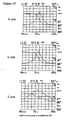
X-axis winding wire 24 and Y-axis winding wire 25 would be the connections represented by SSS, FFF, FFS, FSF, FSS, SFF, SFS, SSF. Comparative trials of these eight types of received sensitivity characteristics with the received sensitivity characteristics of aforementioned CCS show that the CSS connection provides the highest peak value and that the characteristics are arranged according to the peak frequency in the XYZ axes. In short, this indicates that characteristics having no deviation in three axes are obtained. Figure 14 shows the case of a CCS connection while Figure 15 shows the case of an FFF connection. The trial results in Figure 15 indicate deviation of the central frequency due to coupling in the case of an FFF connection. The ordinate in each chart represents the impedance, with one calibration representing 50 KΩ. The abscissa is the frequency. The center of the abscissa is 134.2 KHz and the amplitude of the abscissa is 30 KHz. Tests on the characteristics of CCF revealed characteristics virtually identical with those of CCS. - The structure shown in Figure 11 is provided with eight
terminals 31 to 38 in the three-axis antenna, but a structure in which a three-axis antenna is provided with six terminals in whichterminals X-axis winding wire 24 may be structured from two winding wires and Y-axis winding wire 25 may also be structured from two winding wires. A structure may be adopted in which the terminals 37A, 37B, 38A, 38B connected to the individual center taps XC, YC ofX-axis winding wire 24 and Y-axis winding wire 25 are commonly connected withterminal 35 on the circuit board side for grounding. - An antenna coil unit provided with six external terminals can be implemented by incorporating capacitors C1 to C3 in
case 1. In addition, an antenna coil unit that incorporatesamplifiers 81 to 83 incase 1 can also be implemented. Furthermore, six terminals can be completed by collecting in one terminal each terminus of each winding wire connected to the ground. - Retaining tab 4 in Figure 3 may have a structure that is integrated with
cross-shaped core 2 so as to cover head sections 22aa, 22bb, 23aa, 23bb ofcross-shaped core 2. - Fan shaped
convex member 12 incase 1 shown in Figure 2 is not restricted to this shape. Rectangular or round shapes are also permitted. - Winding as shown in Figure 16 and Figure 17 may be adopted instead of the winding method of
X-axis winding wire 24 shown in Figure 6. Specifically, as shown in Figure 16, the winding origin may be from head section 22aa ofcross-shaped core 2, proceeding toward the root section ofX-axis arm 22a, after which it diagonally straddlesbase section 21 and reaches the root section ofX-axis arm 22b, the other arm, from which point the winding would proceed from the root section of aforementionedX-axis arm 22b toward the side of head section 22bb so that the magnetic flux directions due to winding wires that are wound aboutX-axis arms cross-shaped core 2, proceeding toward the root section ofX-axis arm 22a, after which it straddlesbase section 21 directly to the opposite side to reach the root section ofX-axis arm 22b, the other arm, from which point the winding would proceed from the root section of aforementionedX-axis arm 22b toward the side of head section 22bb so that the magnetic flux due to winding wires that are wound aboutX-axis arms X-axis arm 22a. Of course, the winding technique of winding wire from the root section ofX-axis arm 22b to head section 22bb may be identical. -
- [Figure 1] Perspective diagram showing an embodiment of the antenna coil unit pursuant to the present invention.
- [Figure 2] Perspective diagram showing the case used in the antenna coil unit pursuant to the present invention.
- [Figure 3] Perspective diagram of the retaining tab used in the antenna coil unit pursuant to the present invention.
- [Figure 4] Perspective diagram of the condition in which winding wire is not wound in the three-axis antenna pursuant to the present invention.
- [Figure 5] Perspective diagram of the three-axis antenna pursuant to the present invention.
- [Figure 6] Perspective diagram showing the method of winding the three-axis antenna pursuant to the present invention.
- [Figure 7] Perspective diagram of the condition in which winding wire is not wound in the antenna coil unit pursuant to the present invention.
- [Figure 8] Front view showing an embodiment of the antenna coil unit pursuant to the present invention.
- [Figure 9] A-A cross-sectional view of the antenna coil unit pursuant to the present invention shown in Figure 8.
- [Figure 10] Cross-sectional view for explaining the results concerning alignment in the direction of height of the antenna coil unit pursuant to the present invention.
- [Figure 11] Circuit diagram showing the first embodiment of the receiving device pursuant to the present invention.
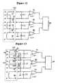
- [Figure 12] Circuit diagram showing the second embodiment of the receiving device pursuant to the present invention.
- [Figure 13] Circuit diagram showing the third embodiment of the receiving device pursuant to the present invention.
- [Figure 14] Diagram showing the frequency characteristics when conducting CCS connection shown in Figure 11 in the receiving device pursuant to the present invention.
- [Figure 15] Diagram showing the frequency characteristics when conducting FFF connection different from Figure 11 in the receiving device pursuant to the present invention.
- [Figure 16] Perspective diagram showing the method of winding the three-axis antenna pursuant to the present invention.
- [Figure 17] Perspective diagram showing the method of winding the three-axis antenna pursuant to the present invention.
-
- 1
- case
- 2
- cross-shaped core
- 4
- retaining tab
- 11
- groove
- 12
- convex member
- 13
- projection
- 21
- base section
- 22a, 22b
- X-axis arms
- 23a, 23b
- Y-axis arms
- 24
- X-axis winding wire
- 25
- Y-axis winding wire
- 26
- Z-axis winding wire
- 81
- first amplifier
- 82
- second amplifier
- 83
- third amplifier
- 84
- reception selection circuit
- 100
- antenna coil unit
Claims (11)
- A three-axis antenna provided with a cross-shaped core having a pair of X-axis arms projecting in the X-axis direction and a pair of Y-axis arms projecting in the Y-axis direction orthogonal to aforementioned X-axis direction in an orthogonal coordinate system,
X-axis winding wire wound about aforementioned X-axis arms,
Y-axis winding wire wound about aforementioned Y-axis arms,
Z-axis winding wire provided in a condition enclosing aforementioned cross-shaped core outside the head sections of aforementioned X-axis arms and the head sections of aforementioned Y-axis arms,
wherein aforementioned Z-axis winding wire is housed in a condition so as to cover the entire head surfaces of the X-axis arms and head surfaces of the Y-axis arms in aforementioned cross-shaped core. - The three-axis antenna of Claim 1 in which aforementioned X-axis winding wire and Y-axis winding wire are wound from the root section of the arm as the winding origin toward the head section of one arm without encircling said head section, after which each winding spans to the head section of the other arm from which point it continues toward aforementioned root section.
- The three-axis antenna of Claim 1 in which each winding origin edge and each winding terminus edge of the X-axis winding wire, the Y-axis winding wire and the Z-axis winding wire is connected to a terminal and the center taps of the X-axis winding wire and the Y-axis winding wire are connected to terminals for a total of eight terminals.
- An antenna coil unit provided with a cross-shaped core having a pair of X-axis arms projecting in the X-axis direction and a pair of Y-axis arms projecting in the Y-axis direction orthogonal to aforementioned X-axis direction in an orthogonal coordinate system,
X-axis winding wire wound about aforementioned X-axis arms,
Y-axis winding wire wound about aforementioned Y-axis arms,
Z-axis winding wire provided in a condition enclosing aforementioned cross-shaped core outside the head sections of aforementioned X-axis arms and the head sections of aforementioned Y-axis arms,
a case with a bottom housing aforementioned cross-shaped core and aforementioned Z-axis winding wire,
the head section of aforementioned X-axis arm and the head section of aforementioned Y-axis arm each being retained when aforementioned cross-shaped core is set in aforementioned case with a bottom, and retaining tabs that determine the position in the Z-axis direction of the X-axis arm and aforementioned Y-axis arm,
wherein aforementioned Z-axis winding wire is housed in aforementioned case with a bottom in a condition so as to cover the entire head surfaces of the X-axis arms and head surfaces of the Y-axis arms in aforementioned cross-shaped core. - The antenna coil unit of Claim 4 in which each winding origin edge and each winding terminus edge of the X-axis winding wire, the Y-axis winding wire and the Z-axis winding wire is connected to a terminal and the center taps of the X-axis winding wire and the Y-axis winding wire are connected to terminals for a total of eight terminals.
- The antenna coil unit of Claim 4 in which aforementioned X-axis winding wire and Y-axis winding wire are wound from the root section of the arm as the winding origin toward the head section of one arm without encircling said head section, after which each winding spans to the head section of the other arm from which point it continues toward aforementioned root section.
- The antenna coil unit of Claim 4 in which aforementioned retaining tab has a projection tab installed so as to catch the winding wire edge.
- A receiving device provided with a three-axis antenna that has a cross-shaped core having a pair of X-axis arms projecting in the X-axis direction and a pair of Y-axis arms projecting in the Y-axis direction orthogonal to aforementioned X-axis direction in an orthogonal coordinate system, said X-axis winding wire being wound about aforementioned X-axis arms and Y-axis winding wire being wound about aforementioned Y-axis arms, Z-axis winding wire provided in a condition enclosing aforementioned cross-shaped core outside the head sections of aforementioned X-axis arms and the head sections of aforementioned Y-axis arms and so as to cover the entire head surfaces of the X-axis arms and head surfaces of the Y-axis arms in aforementioned cross-shaped core,
also with a first amplifier connected to a terminal that is connected to the winding origin and to the winding terminus of aforementioned X-axis,
a second amplifier connected to a terminal that is connected to the winding origin and to the winding terminus of aforementioned Y-axis,
a third amplifier connected to the terminal that is connected to the winding origin and to the winding terminus of aforementioned Z-axis,
and a reception selection circuit that treats the output from any of aforementioned first to third amplifiers as received signals,
wherein the terminal connected to the center taps of aforementioned X-axis winding and aforementioned Y-axis winding and the terminal connected to the winding origin edge of aforementioned Z-axis winding wire are grounded. - The receiving device of Claim 8 in which a terminal is connected to each winding origin edge and each winding terminus edge of the X-axis winding wire, Y-axis winding wire and Z-axis winding wire, and a terminal is connected to the center taps of the X-axis winding wire and the Y-axis winding wire for a total of eight terminals.
- The receiving device of Claim 8 in which aforementioned X-axis winding wire and Y-axis winding wire each begin from the root section of an arm and extend toward the head section of the arm without encircling said head section, after which each winding spans to the head section of the other arm from which point it continues toward aforementioned root section.
- The receiving device of Claim 7 in which the center taps of the X-axis winding wire and the Y-axis winding wire are connected to the circuit board upon which aforementioned first to third amplifiers have been installed.
Priority Applications (1)
| Application Number | Priority Date | Filing Date | Title |
|---|---|---|---|
| EP08010602A EP1968157B1 (en) | 2004-03-12 | 2005-03-10 | Three-axis antenna |
Applications Claiming Priority (2)
| Application Number | Priority Date | Filing Date | Title |
|---|---|---|---|
| JP2004071481 | 2004-03-12 | ||
| PCT/JP2005/004218 WO2005088767A1 (en) | 2004-03-12 | 2005-03-10 | Three-axis antenna, antenna unit, and receiving device |
Related Child Applications (2)
| Application Number | Title | Priority Date | Filing Date |
|---|---|---|---|
| EP08010602A Division EP1968157B1 (en) | 2004-03-12 | 2005-03-10 | Three-axis antenna |
| EP08010602.4 Division-Into | 2008-06-11 |
Publications (3)
| Publication Number | Publication Date |
|---|---|
| EP1727236A1 true EP1727236A1 (en) | 2006-11-29 |
| EP1727236A4 EP1727236A4 (en) | 2007-07-11 |
| EP1727236B1 EP1727236B1 (en) | 2010-08-11 |
Family
ID=34975898
Family Applications (2)
| Application Number | Title | Priority Date | Filing Date |
|---|---|---|---|
| EP08010602A Expired - Lifetime EP1968157B1 (en) | 2004-03-12 | 2005-03-10 | Three-axis antenna |
| EP05720489A Expired - Lifetime EP1727236B1 (en) | 2004-03-12 | 2005-03-10 | Three-axis antenna and receiving device |
Family Applications Before (1)
| Application Number | Title | Priority Date | Filing Date |
|---|---|---|---|
| EP08010602A Expired - Lifetime EP1968157B1 (en) | 2004-03-12 | 2005-03-10 | Three-axis antenna |
Country Status (7)
| Country | Link |
|---|---|
| US (2) | US7616166B2 (en) |
| EP (2) | EP1968157B1 (en) |
| JP (2) | JP4426574B2 (en) |
| KR (1) | KR100881118B1 (en) |
| CN (3) | CN101901963B (en) |
| DE (1) | DE602005022838D1 (en) |
| WO (1) | WO2005088767A1 (en) |
Cited By (7)
| Publication number | Priority date | Publication date | Assignee | Title |
|---|---|---|---|---|
| EP1887587A1 (en) * | 2006-08-12 | 2008-02-13 | Kaschke KG GmbH & Co. | Coil arrangement |
| EP2131444A1 (en) * | 2008-06-03 | 2009-12-09 | Sumida Corporation | Antenna coil for receiving an external magnetic field |
| EP2736121A1 (en) * | 2012-11-27 | 2014-05-28 | Kabushiki Kaisha Tokai Rika Denki Seisakusho | Antenna device |
| EP2736120A1 (en) * | 2012-11-27 | 2014-05-28 | Kabushiki Kaisha Tokai Rika Denki Seisakusho | Antenna device |
| EP2602868A4 (en) * | 2010-08-04 | 2014-08-06 | Toda Kogyo Corp | RF LABEL, MAGNETIC ANTENNA, SUBSTRATE ON WHICH THE RF LABEL IS MOUNTED, AND COMMUNICATION SYSTEM |
| RU2524838C2 (en) * | 2012-08-27 | 2014-08-10 | Федеральное государственное унитарное предприятие "Ростовский-на-Дону научно-исследовательский институт радиосвязи" (ФГУП "РНИИРС") | Triaxial rotary support |
| EP2966655A3 (en) * | 2010-02-15 | 2016-04-13 | Sumida Corporation | Antenna coil |
Families Citing this family (35)
| Publication number | Priority date | Publication date | Assignee | Title |
|---|---|---|---|---|
| RU2321926C2 (en) * | 2003-10-16 | 2008-04-10 | Сумида Корпорейшн | Antenna coil and antenna arrangement |
| JP4519188B2 (en) | 2006-04-07 | 2010-08-04 | スミダコーポレーション株式会社 | Antenna coil |
| CN101401259B (en) * | 2006-04-10 | 2012-06-13 | 胜美达集团株式会社 | Coil part |
| JP3957000B1 (en) * | 2006-07-07 | 2007-08-08 | 株式会社村田製作所 | Antenna coil for board mounting and antenna device |
| JP4724623B2 (en) * | 2006-08-29 | 2011-07-13 | スミダコーポレーション株式会社 | Antenna coil |
| EP2026406A1 (en) * | 2007-08-14 | 2009-02-18 | Oticon A/S | Multipurpose antenna unit |
| GB0724703D0 (en) * | 2007-12-19 | 2008-01-30 | Rhodes Mark | Co-located transmit-receive antenna system |
| JP2009267767A (en) * | 2008-04-25 | 2009-11-12 | Hitachi Ferrite Electronics Ltd | Triaxial receiving antenna device for low frequency |
| US8461719B2 (en) * | 2008-09-27 | 2013-06-11 | Witricity Corporation | Wireless energy transfer systems |
| KR20110117119A (en) | 2009-01-30 | 2011-10-26 | 도다 고교 가부시끼가이샤 | Magnetic antenna, RF tag, and board on which the RF tag is mounted |
| JP4905506B2 (en) * | 2009-06-22 | 2012-03-28 | 株式会社村田製作所 | Antenna device |
| JP2011135560A (en) * | 2009-11-27 | 2011-07-07 | Toko Inc | Antenna coil and manufacturing method thereof |
| JP5660132B2 (en) * | 2010-04-13 | 2015-01-28 | 日立金属株式会社 | Triaxial antenna and core assembly used therefor |
| JPWO2012053089A1 (en) * | 2010-10-21 | 2014-02-24 | 東京特殊電線株式会社 | Coil parts and coil part units |
| US8704721B2 (en) | 2011-08-08 | 2014-04-22 | Rf Technologies, Inc. | Multi-axial resonant ferrite core antenna |
| JP5093412B2 (en) * | 2012-01-12 | 2012-12-12 | 株式会社村田製作所 | Antenna coil and antenna device |
| CN105190995A (en) * | 2013-03-15 | 2015-12-23 | 株式会社理光 | Antenna device |
| JP5913268B2 (en) * | 2013-11-29 | 2016-04-27 | 東光株式会社 | 3-axis antenna |
| JP6179543B2 (en) * | 2014-05-13 | 2017-08-16 | 株式会社村田製作所 | 3-axis antenna |
| KR101873855B1 (en) * | 2015-02-23 | 2018-07-03 | 한국전자통신연구원 | Triaxial sensor and device including the same for measuring magnetic field |
| ES2716882T3 (en) * | 2015-11-04 | 2019-06-17 | Premo Sa | Antenna device for HF and LF operations |
| KR101638310B1 (en) | 2016-01-20 | 2016-07-12 | (주)에프원테크놀로지 | Three-axis coil antenna and a method of manufacturing the same |
| KR101638311B1 (en) | 2016-02-29 | 2016-07-12 | (주)에프원테크놀로지 | Three-axis coil antenna terminal and a method of manufacturing the same |
| WO2017183935A1 (en) * | 2016-04-21 | 2017-10-26 | 주식회사 아모그린텍 | Three-axis low-frequency antenna module and keyless entry system comprising same |
| WO2017183933A1 (en) * | 2016-04-21 | 2017-10-26 | 주식회사 아모그린텍 | Three-axis antenna module and keyless entry system comprising same |
| KR102020799B1 (en) * | 2016-04-21 | 2019-09-11 | 주식회사 아모그린텍 | Low Frequency Antenna and keyless entry system including the same |
| KR102021337B1 (en) * | 2016-04-21 | 2019-09-16 | 주식회사 아모그린텍 | Low Frequency Antenna and keyless entry system including the same |
| WO2017183934A1 (en) * | 2016-04-21 | 2017-10-26 | 주식회사 아모그린텍 | Three-axis antenna module and keyless entry system comprising same |
| WO2018066893A1 (en) * | 2016-10-04 | 2018-04-12 | 주식회사 아모그린텍 | Three-axis antenna module and keyless entry system comprising same |
| CN110192256B (en) * | 2016-11-04 | 2022-03-29 | 普莱默股份公司 | Compact magnetic power cell for power electronic systems |
| CN106602251B (en) * | 2016-12-16 | 2019-06-21 | 无锡科锐漫电子科技有限公司 | Low frequency reception antenna and its manufacturing method |
| CN106952710B (en) * | 2017-05-12 | 2018-10-30 | 福州大学 | A kind of wireless charging magnetic coupling arrangement and its circuit for multi-load |
| EP3404768B1 (en) | 2017-05-18 | 2019-12-04 | Premo, S.A. | Low profile triaxial antenna |
| CN111194506B (en) * | 2017-09-28 | 2022-04-26 | 株式会社村田制作所 | Antenna device and multi-axis antenna device provided with same |
| EP3855566B1 (en) * | 2020-01-23 | 2024-05-01 | Premo, SL | Multiband 3d universal antenna |
Family Cites Families (16)
| Publication number | Priority date | Publication date | Assignee | Title |
|---|---|---|---|---|
| JPS6145618Y2 (en) * | 1980-04-10 | 1986-12-22 | ||
| JPS6286713U (en) * | 1985-11-20 | 1987-06-03 | ||
| JPH08163190A (en) * | 1994-11-30 | 1996-06-21 | Sony Corp | Transceiver |
| JPH095083A (en) * | 1995-06-16 | 1997-01-10 | Tokin Corp | Geomagnetic sensor and manufacturing method thereof |
| DE19718423A1 (en) * | 1997-04-30 | 1998-11-05 | Siemens Ag | Portable signal receiver |
| US6563474B2 (en) * | 2000-12-21 | 2003-05-13 | Lear Corporation | Remote access device having multiple inductive coil antenna |
| JP2002207980A (en) * | 2001-01-09 | 2002-07-26 | Denso Corp | ID tag for attaching metal |
| JP2003092509A (en) | 2001-07-13 | 2003-03-28 | Sumida Corporation | Antenna coil |
| JP3757972B2 (en) | 2001-07-13 | 2006-03-22 | 株式会社デンソー | Antenna coil |
| JP4133609B2 (en) * | 2001-07-13 | 2008-08-13 | スミダコーポレーション株式会社 | Antenna coil |
| US20060152427A1 (en) | 2002-03-05 | 2006-07-13 | Hozumi Ueda | Antenna coil |
| KR100677296B1 (en) * | 2002-03-27 | 2007-02-05 | 엘지전자 주식회사 | Diversity receiver |
| JP3829761B2 (en) * | 2002-06-04 | 2006-10-04 | 株式会社デンソー | Receiving antenna, portable device |
| JP3924512B2 (en) | 2002-06-27 | 2007-06-06 | 株式会社東海理化電機製作所 | Chip multi-axis antenna |
| US6995729B2 (en) * | 2004-01-09 | 2006-02-07 | Biosense Webster, Inc. | Transponder with overlapping coil antennas on a common core |
| US7295168B2 (en) * | 2004-05-20 | 2007-11-13 | Yonezawa Electric Wire Co., Ltd. | Antenna coil |
-
2005
- 2005-03-10 DE DE602005022838T patent/DE602005022838D1/en not_active Expired - Lifetime
- 2005-03-10 EP EP08010602A patent/EP1968157B1/en not_active Expired - Lifetime
- 2005-03-10 CN CN2009102622323A patent/CN101901963B/en not_active Expired - Lifetime
- 2005-03-10 CN CN2005800080185A patent/CN1930733B/en not_active Expired - Lifetime
- 2005-03-10 JP JP2006510981A patent/JP4426574B2/en not_active Expired - Lifetime
- 2005-03-10 WO PCT/JP2005/004218 patent/WO2005088767A1/en not_active Ceased
- 2005-03-10 US US10/592,428 patent/US7616166B2/en active Active
- 2005-03-10 KR KR1020067020976A patent/KR100881118B1/en not_active Expired - Lifetime
- 2005-03-10 CN CN2009102622304A patent/CN101901958B/en not_active Expired - Lifetime
- 2005-03-10 EP EP05720489A patent/EP1727236B1/en not_active Expired - Lifetime
-
2009
- 2009-03-23 JP JP2009069325A patent/JP4547455B2/en not_active Expired - Lifetime
- 2009-08-27 US US12/461,910 patent/US7796091B2/en not_active Expired - Lifetime
Cited By (8)
| Publication number | Priority date | Publication date | Assignee | Title |
|---|---|---|---|---|
| EP1887587A1 (en) * | 2006-08-12 | 2008-02-13 | Kaschke KG GmbH & Co. | Coil arrangement |
| EP2131444A1 (en) * | 2008-06-03 | 2009-12-09 | Sumida Corporation | Antenna coil for receiving an external magnetic field |
| US8077106B2 (en) | 2008-06-03 | 2011-12-13 | Sumida Corporation | Receiving antenna coil |
| EP2966655A3 (en) * | 2010-02-15 | 2016-04-13 | Sumida Corporation | Antenna coil |
| EP2602868A4 (en) * | 2010-08-04 | 2014-08-06 | Toda Kogyo Corp | RF LABEL, MAGNETIC ANTENNA, SUBSTRATE ON WHICH THE RF LABEL IS MOUNTED, AND COMMUNICATION SYSTEM |
| RU2524838C2 (en) * | 2012-08-27 | 2014-08-10 | Федеральное государственное унитарное предприятие "Ростовский-на-Дону научно-исследовательский институт радиосвязи" (ФГУП "РНИИРС") | Triaxial rotary support |
| EP2736121A1 (en) * | 2012-11-27 | 2014-05-28 | Kabushiki Kaisha Tokai Rika Denki Seisakusho | Antenna device |
| EP2736120A1 (en) * | 2012-11-27 | 2014-05-28 | Kabushiki Kaisha Tokai Rika Denki Seisakusho | Antenna device |
Also Published As
| Publication number | Publication date |
|---|---|
| CN101901963A (en) | 2010-12-01 |
| US7796091B2 (en) | 2010-09-14 |
| KR100881118B1 (en) | 2009-02-02 |
| EP1968157A1 (en) | 2008-09-10 |
| US20070195001A1 (en) | 2007-08-23 |
| US20100066626A1 (en) | 2010-03-18 |
| JP2009136022A (en) | 2009-06-18 |
| CN101901958A (en) | 2010-12-01 |
| EP1727236B1 (en) | 2010-08-11 |
| CN101901958B (en) | 2013-06-05 |
| DE602005022838D1 (en) | 2010-09-23 |
| CN101901963B (en) | 2013-06-19 |
| KR20060121991A (en) | 2006-11-29 |
| EP1727236A4 (en) | 2007-07-11 |
| US7616166B2 (en) | 2009-11-10 |
| EP1968157B1 (en) | 2011-05-11 |
| JPWO2005088767A1 (en) | 2008-01-31 |
| CN1930733A (en) | 2007-03-14 |
| JP4547455B2 (en) | 2010-09-22 |
| JP4426574B2 (en) | 2010-03-03 |
| CN1930733B (en) | 2010-05-26 |
| WO2005088767A1 (en) | 2005-09-22 |
Similar Documents
| Publication | Publication Date | Title |
|---|---|---|
| US7796091B2 (en) | Three-axis antenna, antenna unit and receiving device | |
| CN101047280B (en) | Antenna coil | |
| JP4995286B2 (en) | Coil parts | |
| EP2131444B1 (en) | Antenna coil for receiving an external magnetic field | |
| JP2003092509A (en) | Antenna coil | |
| JP2011135560A (en) | Antenna coil and manufacturing method thereof | |
| EP3518344A1 (en) | Antenna device | |
| EP1536516B1 (en) | Circularly polarized wave antenna device | |
| EP4391225A1 (en) | Antenna element and antenna array | |
| US7029335B2 (en) | Electrical connecting device | |
| JPH05136592A (en) | Inverter device | |
| CN113345698A (en) | Circuit board provided with coil component | |
| JP3757972B2 (en) | Antenna coil | |
| JP2005159836A (en) | Antenna device | |
| US20230170616A1 (en) | One-part antenna core | |
| JP2024541522A (en) | Radar sensor having a concave radome | |
| JP3927727B2 (en) | Antenna device | |
| JP4133609B2 (en) | Antenna coil | |
| KR102687847B1 (en) | Bobbin and transformer including the bobbin | |
| US7121882B2 (en) | Electrical connecting device for connecting to a mating device | |
| JPH10327008A (en) | Antenna device | |
| JP2002204040A (en) | Electronic equipment having a printed circuit board | |
| JPH0896902A (en) | Connector | |
| KR20070023681A (en) | Inductor |
Legal Events
| Date | Code | Title | Description |
|---|---|---|---|
| PUAI | Public reference made under article 153(3) epc to a published international application that has entered the european phase |
Free format text: ORIGINAL CODE: 0009012 |
|
| 17P | Request for examination filed |
Effective date: 20060927 |
|
| AK | Designated contracting states |
Kind code of ref document: A1 Designated state(s): DE FR GB |
|
| RIC1 | Information provided on ipc code assigned before grant |
Ipc: H01Q 21/24 20060101ALI20070319BHEP Ipc: H01Q 7/08 20060101ALI20070319BHEP Ipc: H01Q 7/06 20060101AFI20070319BHEP |
|
| DAX | Request for extension of the european patent (deleted) | ||
| RBV | Designated contracting states (corrected) |
Designated state(s): DE FR GB |
|
| A4 | Supplementary search report drawn up and despatched |
Effective date: 20070611 |
|
| 17Q | First examination report despatched |
Effective date: 20070821 |
|
| GRAP | Despatch of communication of intention to grant a patent |
Free format text: ORIGINAL CODE: EPIDOSNIGR1 |
|
| RTI1 | Title (correction) |
Free format text: THREE-AXIS ANTENNA AND RECEIVING DEVICE |
|
| GRAS | Grant fee paid |
Free format text: ORIGINAL CODE: EPIDOSNIGR3 |
|
| GRAA | (expected) grant |
Free format text: ORIGINAL CODE: 0009210 |
|
| AK | Designated contracting states |
Kind code of ref document: B1 Designated state(s): DE FR GB |
|
| REG | Reference to a national code |
Ref country code: GB Ref legal event code: FG4D |
|
| REF | Corresponds to: |
Ref document number: 602005022838 Country of ref document: DE Date of ref document: 20100923 Kind code of ref document: P |
|
| PLBE | No opposition filed within time limit |
Free format text: ORIGINAL CODE: 0009261 |
|
| STAA | Information on the status of an ep patent application or granted ep patent |
Free format text: STATUS: NO OPPOSITION FILED WITHIN TIME LIMIT |
|
| 26N | No opposition filed |
Effective date: 20110512 |
|
| REG | Reference to a national code |
Ref country code: DE Ref legal event code: R097 Ref document number: 602005022838 Country of ref document: DE Effective date: 20110512 |
|
| REG | Reference to a national code |
Ref country code: FR Ref legal event code: CA Effective date: 20140917 |
|
| REG | Reference to a national code |
Ref country code: FR Ref legal event code: PLFP Year of fee payment: 12 |
|
| REG | Reference to a national code |
Ref country code: FR Ref legal event code: CA Effective date: 20160822 |
|
| REG | Reference to a national code |
Ref country code: FR Ref legal event code: PLFP Year of fee payment: 13 |
|
| REG | Reference to a national code |
Ref country code: FR Ref legal event code: PLFP Year of fee payment: 14 |
|
| PGFP | Annual fee paid to national office [announced via postgrant information from national office to epo] |
Ref country code: DE Payment date: 20240320 Year of fee payment: 20 Ref country code: GB Payment date: 20240320 Year of fee payment: 20 |
|
| PGFP | Annual fee paid to national office [announced via postgrant information from national office to epo] |
Ref country code: FR Payment date: 20240321 Year of fee payment: 20 |
|
| REG | Reference to a national code |
Ref country code: DE Ref legal event code: R071 Ref document number: 602005022838 Country of ref document: DE |
|
| REG | Reference to a national code |
Ref country code: GB Ref legal event code: PE20 Expiry date: 20250309 |
|
| PG25 | Lapsed in a contracting state [announced via postgrant information from national office to epo] |
Ref country code: GB Free format text: LAPSE BECAUSE OF EXPIRATION OF PROTECTION Effective date: 20250309 |