EP1726889A1 - Method for controlling an air conditioning unit - Google Patents
Method for controlling an air conditioning unit Download PDFInfo
- Publication number
- EP1726889A1 EP1726889A1 EP06252456A EP06252456A EP1726889A1 EP 1726889 A1 EP1726889 A1 EP 1726889A1 EP 06252456 A EP06252456 A EP 06252456A EP 06252456 A EP06252456 A EP 06252456A EP 1726889 A1 EP1726889 A1 EP 1726889A1
- Authority
- EP
- European Patent Office
- Prior art keywords
- vent
- air
- vane
- cooling
- mode
- Prior art date
- Legal status (The legal status is an assumption and is not a legal conclusion. Google has not performed a legal analysis and makes no representation as to the accuracy of the status listed.)
- Withdrawn
Links
- 238000000034 method Methods 0.000 title claims abstract description 50
- 238000004378 air conditioning Methods 0.000 title description 2
- 238000001816 cooling Methods 0.000 claims abstract description 93
- 238000010438 heat treatment Methods 0.000 claims abstract description 83
- 238000007664 blowing Methods 0.000 claims abstract description 78
- 238000001914 filtration Methods 0.000 claims description 9
- 230000004888 barrier function Effects 0.000 description 14
- 239000003381 stabilizer Substances 0.000 description 9
- 239000003507 refrigerant Substances 0.000 description 8
- XLYOFNOQVPJJNP-UHFFFAOYSA-N water Substances O XLYOFNOQVPJJNP-UHFFFAOYSA-N 0.000 description 8
- 238000000926 separation method Methods 0.000 description 4
- 102220486681 Putative uncharacterized protein PRO1854_S10A_mutation Human genes 0.000 description 2
- 238000010586 diagram Methods 0.000 description 2
- 239000000428 dust Substances 0.000 description 2
- 238000009434 installation Methods 0.000 description 2
- 238000012986 modification Methods 0.000 description 2
- 230000004048 modification Effects 0.000 description 2
- 238000011045 prefiltration Methods 0.000 description 2
- 230000000630 rising effect Effects 0.000 description 2
- 102220470087 Ribonucleoside-diphosphate reductase subunit M2_S20A_mutation Human genes 0.000 description 1
- 230000001143 conditioned effect Effects 0.000 description 1
- 239000000470 constituent Substances 0.000 description 1
- 238000007599 discharging Methods 0.000 description 1
- 230000000694 effects Effects 0.000 description 1
- 239000004973 liquid crystal related substance Substances 0.000 description 1
Images





Classifications
-
- F—MECHANICAL ENGINEERING; LIGHTING; HEATING; WEAPONS; BLASTING
- F24—HEATING; RANGES; VENTILATING
- F24F—AIR-CONDITIONING; AIR-HUMIDIFICATION; VENTILATION; USE OF AIR CURRENTS FOR SCREENING
- F24F1/00—Room units for air-conditioning, e.g. separate or self-contained units or units receiving primary air from a central station
- F24F1/0007—Indoor units, e.g. fan coil units
- F24F1/0011—Indoor units, e.g. fan coil units characterised by air outlets
-
- F—MECHANICAL ENGINEERING; LIGHTING; HEATING; WEAPONS; BLASTING
- F24—HEATING; RANGES; VENTILATING
- F24F—AIR-CONDITIONING; AIR-HUMIDIFICATION; VENTILATION; USE OF AIR CURRENTS FOR SCREENING
- F24F1/00—Room units for air-conditioning, e.g. separate or self-contained units or units receiving primary air from a central station
- F24F1/0007—Indoor units, e.g. fan coil units
- F24F1/0043—Indoor units, e.g. fan coil units characterised by mounting arrangements
- F24F1/0057—Indoor units, e.g. fan coil units characterised by mounting arrangements mounted in or on a wall
-
- F—MECHANICAL ENGINEERING; LIGHTING; HEATING; WEAPONS; BLASTING
- F24—HEATING; RANGES; VENTILATING
- F24F—AIR-CONDITIONING; AIR-HUMIDIFICATION; VENTILATION; USE OF AIR CURRENTS FOR SCREENING
- F24F11/00—Control or safety arrangements
- F24F11/30—Control or safety arrangements for purposes related to the operation of the system, e.g. for safety or monitoring
-
- F—MECHANICAL ENGINEERING; LIGHTING; HEATING; WEAPONS; BLASTING
- F24—HEATING; RANGES; VENTILATING
- F24F—AIR-CONDITIONING; AIR-HUMIDIFICATION; VENTILATION; USE OF AIR CURRENTS FOR SCREENING
- F24F11/00—Control or safety arrangements
- F24F11/70—Control systems characterised by their outputs; Constructional details thereof
- F24F11/80—Control systems characterised by their outputs; Constructional details thereof for controlling the temperature of the supplied air
- F24F11/81—Control systems characterised by their outputs; Constructional details thereof for controlling the temperature of the supplied air by controlling the air supply to heat-exchangers or bypass channels
-
- F—MECHANICAL ENGINEERING; LIGHTING; HEATING; WEAPONS; BLASTING
- F24—HEATING; RANGES; VENTILATING
- F24F—AIR-CONDITIONING; AIR-HUMIDIFICATION; VENTILATION; USE OF AIR CURRENTS FOR SCREENING
- F24F1/00—Room units for air-conditioning, e.g. separate or self-contained units or units receiving primary air from a central station
- F24F1/0007—Indoor units, e.g. fan coil units
- F24F1/0018—Indoor units, e.g. fan coil units characterised by fans
- F24F1/0033—Indoor units, e.g. fan coil units characterised by fans having two or more fans
-
- F—MECHANICAL ENGINEERING; LIGHTING; HEATING; WEAPONS; BLASTING
- F24—HEATING; RANGES; VENTILATING
- F24F—AIR-CONDITIONING; AIR-HUMIDIFICATION; VENTILATION; USE OF AIR CURRENTS FOR SCREENING
- F24F2221/00—Details or features not otherwise provided for
- F24F2221/54—Heating and cooling, simultaneously or alternatively
Definitions
- the present invention relates to a method for controlling an air conditioner, and more particularly, to a method for controlling an air conditioner, which is capable of controlling a vent provided at the air conditioner to be selectively used as an air inlet for receiving indoor air or an air outlet for discharging the received air.
- air conditioners are used to cool or heat a confined space such as a room, in order to provide a comfortable indoor environment for users.
- Such an air conditioner includes a refrigerant cycle including a compressor, a 4-way valve, an outdoor heat exchanger (a condenser or evaporator), an expansion device, and an indoor heat exchanger (an evaporator or condenser).
- Air conditioners which have such a configuration, are mainly classified into a separation type and an integrated type.
- Both the separation type air conditioner and the integrated type air conditioner have the same function.
- an indoor unit in which a cooling/heat-radiating device, an indoor fan, and an indoor fan motor are installed
- an outdoor unit in which a heat-radiating/cooling device, a compressor, an outdoor fan, and an outdoor fan motor are installed
- indoor and outdoor units thereof are integrated so that cooling and heat-radiating functions are integrated.
- Such an integrated type air conditioner is directly installed on an outer wall or window of a house.
- FIGs. 1 and 2 An example of a conventional separation type air conditioner will be described with reference to FIGs. 1 and 2.
- the conventional air conditioner includes a chassis 102, a front grill 110 coupled to a front wall of the chassis 102, an inlet grill 112 hingably connected to a front wall of the front grill 110, and a motor 114 mounted to the chassis 102.
- the conventional air conditioner also includes a blowing fan 116 connected to the motor 114, and a heat exchanger 118 which heat-exchanges air introduced into the air conditioner with a refrigerant passing through the heat exchanger 118.
- the front grill 110 includes an air inlet 104 formed through the front wall of the front grill 110.
- An upper inlet grill 106 is provided at a top wall of the front grill 110 such that the upper inlet grill 106 is integral with the front grill 110.
- An air outlet 108 is formed through a lower portion of the front wall of the front grill 110 or through a bottom wall of the front grill 110.
- a pre-filter 105 is arranged inside the front grill 110, to filter air introduced through the air inlet 104, and thus, to remove foreign matter from the air.
- the inlet grill 112 protects the air inlet 104 and pre-filter 105.
- the inlet grill 112 is hingably connected to the top wall of the front grill 110 at a top wall of the inlet grill 112.
- a condensed water receiver 119 is arranged at a lower portion of the front grill 110 inside the front grill, to receive condensed water falling from the heat exchanger 118.
- a louver 120 and an outlet grill 124 are also arranged at a lower portion of the front grill 110 inside the front grill 110.
- the louver 120 changes the lateral flow direction of air discharged out of the air outlet 108.
- the outlet grill 124 includes a vane 122 which changes the vertical flow direction of the discharged air.
- the introduced indoor air is cooled or heated by a refrigerant, which passes through the indoor heat exchanger 118, while passing around the indoor heat exchanger 118.
- the cooled or heated air is discharged into a room, to be cooled or heated by the heat exchanger, in accordance with guidance of the louver 120 and vane 122 after passing through the blowing fan 116.
- the conventional air conditioner has a problem in that, where the installation level of the air conditioner is low, the time taken to uniformly spread throughout the room is lengthened because indoor air is discharged into the room through the lower side of the air conditioner after being introduced into the front and top sides of the air conditioner. On the other hand, where the installation level of the air conditioner is high, there is a problem in that increased uncomfortableness occurs during a heating operation because hot air is discharged toward the face of the user.
- An object of the present invention devised to solve the above-mentioned problems lies in providing a method for controlling an air conditioner, which is capable of reversely changing the introduction/discharge direction of air in accordance with a user's desire, thereby efficiently air-conditioning a room during a cooling/heating operation.
- Another object of the present invention is to provide a method for controlling an air conditioner, which is capable of controlling the discharge direction of hot/cold air, to cause the hot air to be discharged out of a lower portion of the air conditioner during a heating operation such that the hot air uniformly heats a room while rising, thereby preventing the user from being uncomfortable, and to cause the cold air to be discharged out of an upper portion of the air conditioner during a cooling operation such that the cold air reaches even a far region of the room while falling, thereby uniformly cooling the room.
- the objects of the present invention can be achieved by providing a method for controlling an air conditioner, comprising: an operation mode inputting step of selecting a cooling mode or a heating mode of the air conditioner, and inputting the selected operation mode; a cooling operation step of controlling a blowing unit by a controller when the operation mode selected at the operation mode inputting step is the cooling mode such that indoor air is discharged out of the air conditioner through a first vent after being sucked into the air conditioner through a second vent; and a heating operation step of controlling the blowing unit by the controller when the operation mode selected at the operation mode inputting step is the heating mode such that indoor air is discharged out of the air conditioner through the second vent after being sucked into the air conditioner through the first vent.
- the present invention provides a method for controlling an air conditioner including a body provided with a first vent and a second vent, through which introduction or discharge of air is selectively carried out, a cooling blower and a heating blower which are arranged in the body, to blow air in opposite directions, respectively, a heat exchanger which is arranged in the body, to cool or heat the blown air, a first vane which controls an opening degree of the first vent and a discharge direction of the air discharged through the first vent, a first vane motor which hingably rotates the first vane by a predetermined angle, a second vane which controls an opening degree of the second vent and a discharge direction of the air discharged through the second vent, a second vane motor which hingably rotates the second vane by a predetermined angle, and a controller which controls the cooling blower, the heating blower, and the first and second vane motors, the method comprising: an operation mode inputting step of selecting a cooling mode or a heating mode of the air
- the present invention provides a method for controlling an air conditioner including a body provided with a first vent and a second vent, through which introduction or discharge of air is selectively carried out, a cooling blower and a heating blower which are arranged in the body, and can blow air while rotating in either a normal direction or a reverse direction, a heat exchanger which is arranged in the body, to cool or heat the blown air, a first vane which controls an opening degree of the first vent and a discharge direction of the air discharged through the first vent, a first vane motor which hingably rotates the first vane by a predetermined angle, a second vane which controls an opening degree of the second vent and a discharge direction of the air discharged through the second vent, a second vane motor which hingably rotates the second vane by a predetermined angle, and a controller which controls the first and second blowers and the first and second vane motors, the method comprising: an operation mode inputting step of selecting a cooling mode or a
- the invention also provides air conditioner apparatus adapted to put the above methods into effect.
- the air conditioner has a configuration in which air A is introduced into a lower portion of the air conditioner during a cooling operation, and is then discharged out of an upper portion of the air conditioner after heat-exchanging with a refrigerant, as shown in FIG. 3, whereas air B is introduced into the upper portion of the air conditioner during a heating operation, and is then discharged out of the lower portion of the air conditioner after heat-exchanging with the refrigerant, as shown in FIG. 4.
- air is introduced into the air conditioner 1 through a lower vent 4 during a cooling operation, and is then discharged out of the air conditioner through an upper vent 2 after being cooled.
- air is introduced into the air conditioner through the upper vent 2 during a heating operation, and is then discharged out of the air conditioner through the lower vent 4 after being heated.
- the upper vent 2 and lower vent 4 are formed through top and bottom walls of a body 10 of the air conditioner, respectively, to receive or discharge air.
- a blowing unit 70 is arranged in the body 10. The blowing unit 70 sucks indoor air through one of the upper and lower vents 2 and 4, and discharges the sucked air through the other one of the upper and lower vents 2 and 4.
- An air guide passage P is defined in the body 10 such that the air guide passage P extends vertically.
- the body 10 includes a main chassis 12, and a front panel assembly 20 which covers the overall surface of the main chassis 12.
- the body 10 also includes an upper inlet/outlet unit 30 which is arranged at an upper portion of the main chassis 12, to control a flow of air flowing through the upper vent 2, and a lower inlet/outlet unit 40 which is arranged at a lower portion of the main chassis 12, to control a flow of air flowing through the lower vent 4.
- the main chassis 12 is mounted to a wall of a room, to be air-conditioned by the air conditioner, by a supporter (not shown) fixed to the room wall.
- An upper air guide 14 and a lower air guide 15 are formed at the main chassis 12, to define the air guide passage P which guides air passing between the main chassis 12 and the front panel assembly 20.
- the upper air guide 14 has a round surface so that it forms a scroll housing of an upper blowing fan 74 as will be described hereinafter.
- the lower air guide 14 preferably has a round surface so that it forms a scroll housing of a lower blowing fan 84 as will be described hereinafter.
- a heat exchanger 18 is arranged between the main chassis 12 and the front panel assembly 20.
- the heat exchanger 18 is arranged between the front side of the upper blowing fan 74 and the upper side of the lower blowing fan 84. Also, the heat exchanger 18 is arranged such that the top of the heat exchanger 18 is adjacent to the front wall of the body 10, and the bottom of the heat exchanger 18 is adjacent to the bottom of the upper air guide 14. That is, the heat exchanger 18 is arranged across the air guide passage P.
- a condensed water receiver 19 is formed at the main chassis 12 such that the condensed water receiver 19 is downwardly protruded from a lower end of the main chassis 12.
- the condensed water receiver 19 is arranged beneath a rear end of the heat exchanger 18, to receive condensed water falling from the heat exchanger 18.
- Upper lateral barriers 14A and 14B are protruded from the upper portion of the main chassis 12 at opposite sides of the main chassis 12, respectively.
- the upper lateral barriers 14A and 14B function to support the upper blowing fan 74 received in the upper air guide 14 at opposite sides of the upper air guide 14, and to prevent air blown by the upper blowing fan 74 from being laterally leaked.
- One of the upper lateral barriers 14A and 14B namely, the upper lateral barrier 14A, has a bearing mount 14D to which an upper bearing 74c for rotatably supporting the upper blowing fan 74 is mounted.
- the other upper lateral barrier 14B has an axial through hole 14E through which a rotating shaft 76a of an upper fan motor 76 extends.
- An upper supporter 14F is fastened to the upper lateral barrier 14A having the bearing mount 14D by means of screws.
- the upper supporter 14F functions to receive the upper bearing 74c, and thus, to rotatably support the upper blowing fan 74 together with the upper lateral barrier 14A.
- the upper supporter 14F also functions to prevent air blown by the upper blowing fan 74 from being laterally leaked.
- Lower lateral barriers 15A and 15B are protruded from the lower portion of the main chassis 12 at opposite sides of the main chassis 12, respectively.
- the lower lateral barriers 15A and 15B function to support the lower blowing fan 84 received in the lower air guide 15 at opposite sides of the lower air guide 15, and to prevent air blown by the lower blowing fan 84 from being laterally leaked.
- One of the lower lateral barriers 15A and 15B namely, the lower lateral barrier 15A, has a bearing mount 15D to which a lower bearing 84c for rotatably supporting the lower blowing fan 84 is mounted.
- the other lower lateral barrier 15B has an axial through hole 15E through which a rotating shaft 86a of a lower fan motor 86 extends.
- a lower supporter 15F is fastened to the lower lateral barrier 15A having the bearing mount 15D by means of screws.
- the lower supporter 15F functions to receive the lower bearing 84c, and thus, to rotatably support the lower blowing fan 84 together with the lower lateral barrier 15A.
- the lower supporter 15F also functions to prevent air blown by the lower blowing fan 84 from being laterally leaked.
- the upper supporter 14F and lower supporter 15F also function to firmly support the upper and lower portions of the heat exchanger 18 at one side of the heat exchanger 18, respectively.
- the blowing unit 70 includes constituent elements respectively arranged at the upper and lower portion of the body 10 inside the body 10.
- the blowing unit 70 includes a cooling blower 72 arranged at the upper portion of the body 10 inside the body 10, and a heating blower 82 arranged at the lower portion of the body 10 inside the body 10.
- the cooling blower 72 sucks indoor air A via the lower inlet/outlet unit 40, and discharges the indoor air A via the upper inlet/outlet unit 30 after causing the indoor air A to pass through the heat exchanger 18.
- the heating blower 82 sucks indoor air B via the upper inlet/outlet unit 30, and discharges the indoor air B via the lower inlet/outlet unit 40 after causing the indoor air B to pass through the heat exchanger 18.
- the cooling blower 72 includes the upper blowing fan 74 and upper fan motor 76.
- the upper blowing fan 74 is arranged at the upper portion of the body 10 inside the body 10 such that the upper blowing fan 74 extends laterally.
- the upper fan motor 76 is mounted to the main chassis 12 such that the upper fan motor 76 is arranged at one side of the upper blowing fan 74, to rotate the upper blowing fan 74.
- the upper fan motor 76 is mounted to an upper motor mount 12a formed at one side of the main chassis 12.
- the upper blowing fan 74 is a cross flow fan which has blades adapted to upwardly blow air.
- the upper blowing fan 74 includes a left rotating shaft 74a which is protruded from a left end of the upper blowing fan 74, and is coupled to the upper bearing 74c such that the left rotating shaft 74a is rotatably supported by the upper bearing 74c.
- the upper blowing fan 74 also includes a right rotating shaft 74b which is protruded from a right end of the upper blowing fan 74, and is coupled to the rotating shaft 76a of the upper fan motor 76 through the axial through hole 14E, to receive a rotating force from the rotating shaft 76a.
- the upper fan motor 76 rotates the upper blowing fan 74 during the cooling operation of the air conditioner, and stops the upper blowing fan 74 during the heating operation of the air conditioner.
- the heating blower 82 includes the lower blowing fan 84 and lower fan motor 86.
- the lower blowing fan 84 is arranged at the lower portion of the body 10 inside the body 10 such that the lower blowing fan 84 extends laterally while being parallel to the upper blowing fan 74.
- the lower fan motor 86 is mounted to the main chassis 12 such that the lower fan motor 86 is arranged at one side of the lower blowing fan 84, to rotate the lower blowing fan 84.
- the lower fan motor 86 is mounted to a lower motor mount 12b formed at one side of the main chassis 12.
- the lower blowing fan 84 is a cross flow fan which has blades adapted to downwardly blow air.
- the lower blowing fan 84 includes a left rotating shaft 84a which is protruded from a left end of the lower blowing fan 84, and is coupled to the lower bearing 84c such that the left rotating shaft 84a is rotatably supported by the lower bearing 84c.
- the lower blowing fan 84 also includes a right rotating shaft 84b which is protruded from a right end of the lower blowing fan 84, and is coupled to the rotating shaft 86a of the lower fan motor 86 through the axial through hole 15E, to receive a rotating force from the rotating shaft 86a.
- the lower fan motor 86 stops the lower blowing fan 84 during the cooling operation of the air conditioner, and rotates the lower blowing fan 84 during the heating operation of the air conditioner.
- the upper fan motor 76 and lower fan motor 86 are vertically arranged at the left or right side of the body 10 inside the body 10, taking connection of electric wires into consideration.
- the fan motors 76 and 86 may be diagonally arranged, taking into consideration generation of heat from the fan motors 76 and 86.
- the upper fan motor 76 and lower fan motor 86 are vertically arranged at the right side of the body 10 inside the body 10, the upper fan motor 76 and lower fan motor 86 rotate the upper blowing fan 74 and lower blowing fan 84 in opposite directions, respectively, such that, when the upper blowing fan 74 is rotated in a clockwise direction, the lower blowing fan 74 is rotated in a counterclockwise direction.
- a control box 99 is arranged at one side of the body 10 (the right side in the illustrated embodiment).
- the control box 99 contains electric elements for controlling operations of the upper fan motor 76 and lower fan motor 86 in accordance with a cooling/heating mode of the air conditioner.
- the control box 99 is connected to the upper fan motor 76 and lower fan motor 86 via electric wires 99a and 99b.
- the control box 99 is fixed to one of the main chassis 12 and front panel assembly 20 such that the control box 99 is arranged between the main chassis 12 and the front panel assembly 20.
- the control box 99 may be arranged such that it covers the front sides of the upper fan motor 76 and lower fan motor 86. Alternatively, the control box 99 may be arranged such that it is interposed between the upper motor mount 12a and the lower motor mount 12b.
- the front panel assembly 20 defines the air guide passage P, together with the main chassis 12.
- the front panel assembly 20 includes a front case 22 which is open at the front side thereof, and a front panel 24 which is coupled to the front side of the front case 22, to close the front side of the front case 22.
- the front panel 24 may be separably coupled to the front side of the front case 22.
- the front panel 24 may be integrated with the front side of the front case 22.
- a particular picture, photograph, design, or color may be printed on the front panel 24.
- the front panel 24 is provided, at a particular portion thereof, with a transparent window 24a.
- a display device 24b may be mounted to the front panel 24 at the rear of the transparent window 24a, to display various information of the air conditioner.
- the display device 24b may be a light emitting diode (LED), a liquid crystal display (LCD), an organic electroluminescent (EL) display, or the like.
- the front panel 24 is configured to have the display device 24b at a lower portion of the front panel 24 in the illustrated embodiment, the entire portion of the front panel 24 may be constituted by a display device.
- the front panel 24 may be configured in the form of a picture frame such that a photograph is put in the front panel 24.
- the upper inlet/outlet unit 30 includes an upper stabilizer 32, at which the upper vent 2 is formed, an upper vane 36 which controls the flow direction of air passing through the upper vent 2, and an upper vane motor 38 which hingably rotates the upper vane 36 by a desired angle.
- the upper vane motor 38 hingably rotates the upper vane 36 between a maximum open position C and a minimum open position D during the cooling operation, to control the flow direction and range of air A' discharged through the upper vent 2.
- the "flow direction of air” will also be simply referred to as “wind direction”.
- This mode is referred to as a "wind direction variation mode of the vane”.
- the upper vane motor 38 fixes the upper vane 37 at the maximum open position C, as shown in FIG. 7, in order to enable a maximum amount of indoor air B to be introduced into the air conditioner through the upper vent 2. This mode is referred to as an "open mode of the vane".
- the upper vane motor 38 hingably rotates the upper vane 36 to a closed position E, in order to close the upper vent 2. This mode is referred to as a "close mode of the vane”.
- the lower inlet/outlet unit 40 includes a lower stabilizer 42, at which the condensed water receiver 41 for receiving condensed water falling from the heat exchanger 18 is formed, together with the lower vent 4.
- the lower inlet/outlet unit 40 also includes a lower vane 46 which controls the flow direction of air passing through the lower vent 4, and a lower vane motor 48 which hingably rotates the lower vane 46 by a desired angle.
- the lower vane motor 48 operates the lower vane 46 in an "open mode". That is, the lower vane motor 48 fixes the lower vane 46 at the maximum open position C during the cooling operation, as shown in FIG. 6, to allow the lower vane 46 to guide indoor air A such that a maximum amount of indoor air A is sucked into the air conditioner through the lower vent 4.
- the lower vane motor 48 hingably rotates the lower vane 46 between the maximum open position C and a minimum open position D during the heating operation, to control the flow direction and range of air B discharged through the lower vent 4. That is, the lower vane motor 48 operates in a "wind direction variation mode" during the heating operation of the heat exchanger.
- the lower vane motor 48 hingably rotates the lower vane 46 to a closed position E, in order to close the lower vent 4.
- the air conditioner further includes an upper filter unit 50 which filters air passing through the upper vent 2, and a lower filter unit 60 which filters air passing through the lower vent 4.
- the upper filter unit 50 includes an upper filter 52 which filters air B introduced into the upper vent 2, to remove foreign matter from the introduced air B, an upper filter holder 54 which separably holds the upper filter 52, and is hingably mounted to the upper vent 2, and an upper filter motor 56 which hingably rotates the upper filter holder 54 by a desired angle.
- the upper filter motor 56 is mounted to the upper inlet/outlet unit 30.
- the upper filter motor 56 hingably rotates the upper filter holder 54 such that the upper filter 52 approximately comes into contact with the upper stabilizer 32, thereby causing the upper vent 2 to be completely opened (this mode is referred to as a "shifting mode"), as shown in FIG. 6.
- the upper filter motor 56 hingably rotates the upper filter holder 54 such that the upper filter 52 is coupled to the upper vent 2 (this mode is referred to as a "filtering mode"), as shown in FIG. 7.
- the lower filter unit 60 includes a lower filter 62 which filters air A introduced into the lower vent 4, to remove foreign matter from the introduced air A, a lower filter holder 64 which separably holds the lower filter 62, and is hingably mounted to the lower vent 4, and a lower filter motor 66 which hingably rotates the lower filter holder 64 by a desired angle.
- the lower filter motor 66 is mounted to the lower inlet/outlet unit 40.
- the lower filter motor 66 hingably rotates the lower filter holder 64 such that the lower filter 62 is coupled to the lower vent 4, as shown in FIG. 6.
- the lower filter motor 66 hingably rotates the lower filter holder 64 such that the lower filter 62 approximately comes into contact with the lower stabilizer 42, thereby causing the lower vent 4 to be completely opened, as shown in FIG. 7.
- FIG. 8 is a block diagram illustrating a configuration for controlling the air conditioner having the above-described configuration.
- the air conditioner includes an input part 94 which inputs a signal for selection of the cooling or heating operation of the heat exchanger.
- the input part 94 is connected to a controller 97 which not only controls the upper vane motor 38, lower vane motor 48, upper filter motor 56, lower filter motor 66, upper fan motor 76, and lower fan motor 86, but also controls a compressor 95 and an outdoor fan motor 96.
- the compressor 95 and outdoor fan motor 96 constitute an outdoor unit.
- the controller 97 not only controls operations of the upper vane motor 38, lower vane motor 48, upper filter motor 56, lower filter motor 66, upper fan motor 76, and lower fan motor 86, but also controls operations of the compressor 95 and outdoor fan motor 96, to cause the selected operation mode to be executed.
- the input part 94 may be built in one side of the air conditioner. Alternatively, the input part 94 may be configured in the form of a remote controller.
- control method will be described in conjunction with the cooling operation of the air conditioner with reference to FIGs. 6 and 9.
- the upper vane motor 38 runs in the wind direction variation mode, thereby continuously hingably rotating the upper vane 36 between the maximum open position C and the minimum open position D (S11).
- the lower vane motor 48 runs in the open mode, thereby hingably rotating the lower vane 46 to the maximum open position C (S12).
- the upper filter motor 56 runs in the shifting mode, to maintain the upper filter 52 in a state of being in contact with the upper stabilizer 32 (S13).
- the lower filter motor 66 runs in the filtering mode, to hingably rotate the lower filter holder 64 such that the lower filter 62 is coupled to the lower vent 4 (S14).
- the upper fan motor 76 runs to rotate the upper blowing fan 74 (S15).
- indoor air A is sucked into the air conditioner through the lower vent 4, to flow upwardly in the air conditioner.
- the air sucked through the lower vent 4 is filtered by the lower filter 62, to remove foreign matter such as dust from the sucked air.
- the filtered air then flows along the air guide passage P defined between the main chassis 12 and the front panel assembly 20.
- the air flowing through the air guide passage P heat-exchanges with the refrigerant passing through the heat exchanger 18, while passing around the heat exchanger 18. Thereafter, the air is upwardly blown after passing through the upper blowing fan 74.
- the cold air A' which is discharged out of the front upper portion of the air conditioner in the above-described manner, falls just like shower while being widely spread over the upper portion of the room.
- the cold air A' reaches even a far region of the room, thereby uniformly cooling the entire portion of the room.
- the upper vane motor 38 and lower vane motor 48 hingably rotate the upper vane 36 and lower vane 46 to the closed positions E thereof, to close the upper and lower vents 2 and 4, respectively.
- the heating operation of the air conditioner is carried out in a reverse manner to the above-described cooling operation.
- the lower vane motor 48 runs in the wind direction variation mode, thereby hingably rotating the lower vane 46 between the maximum open position C and the minimum open position D (S21).
- the upper vane motor 38 runs in the open mode, to hingably rotate the upper vane 36 to the maximum open position C, and then stops the upper vane 36 at the maximum open position C (S22).
- the upper filter motor 56 runs in the filtering mode, to hingably rotate the upper filter holder 54 such that the upper filter 52 is coupled to the upper vent 2 (S23).
- the lower filter motor 66 runs in the shifting mode, to cause the lower filter 62 to come into contact with the lower stabilizer 42 (S24).
- the lower fan motor 86 runs to rotate the lower blowing fan 84 in a state in which the upper blowing fan 74 is stopped (S25).
- indoor air B is sucked into the air conditioner through the upper vent 2, to flow downwardly in the air conditioner.
- the air sucked through the upper vent 2 is filtered by the upper filter 62, to remove foreign matter such as dust from the sucked air.
- the filtered air then flows along the air guide passage P defined between the main chassis 12 and the front panel assembly 20.
- the air flowing through the air guide passage P heat-exchanges with the refrigerant passing through the heat exchanger 18, while passing around the heat exchanger 18. As a result, the air is heated. Thereafter, the heated air is downwardly blown after passing through the lower blowing fan 84.
- the lower vane motor 48 controls the discharge direction of the hot air B' by continuously hingably rotating the lower vane 46 between the maximum open position C and the minimum open position D.
- the hot air B' which is discharged out of the front lower portion of the air conditioner in the above-described manner, rises upwardly after being widely spread over the lower portion of the room.
- the hot air B' reaches even a far region of the room, thereby uniformly heating the entire portion of the room.
- the upper vane motor 38 and lower vane motor 48 hingably rotate the upper vane 36 and lower vane 46 to the closed positions E thereof, to close the upper and lower vents 2 and 4, respectively.
- each of the upper vent 2 and lower vent 4 selectively functions as an inlet or outlet in accordance with the operation mode, to discharge cold air or hot air in a direction desired by the user.
- the controller 95 (FIG. 8) controls the upper vane motor 38 and lower vane motor 48 to run in the wind direction variation mode in a forced manner.
- the vane motors 38 and 48 which drive the discharge-side vanes, may selectively run in the wind direction variation mode or in the open mode during the cooling and heating operations in accordance with a selection by the user or controller 95 (FIG. 8).
- the upper vane motor 38 runs in the wind direction variation mode, to swing the upper vane 36 between the maximum open position C and the minimum open position D (S11).
- the lower vane motor 48 runs in the open mode, to hingably rotate the lower vane 46 to the maximum open position C (S12).
- the upper filter motor 56 runs in the shifting mode, to maintain the upper filter 52 in a state of being in contact with the upper stabilizer 32 (S13). Also, the lower filter motor 66 runs in the filtering mode, to position the lower filter 62 such that the lower filter 62 is coupled to the lower vent 4 (S14).
- the upper fan motor 76 runs to rotate the upper blowing fan 74 (S15).
- the upper vane motor 38 runs in the open mode, to hingably rotate the upper vane 36 to the maximum open position C, and then stops the upper vane 36 at the maximum open position C such that the upper vane 36 is maintained at the maximum open position C (S11a).
- the lower vane 46 is swung between the maximum open position C and the minimum open position D by the lower vane motor 48, to control the discharge direction of hot air (S21 to S25).
- the air conditioner according to the above-described embodiment is configured such that the vents 2 and 4 are formed at the upper and lower sides of the body 10, to discharge conditioned air out of the upper or lower sides of the air conditioner.
- vents may be formed at the left and right sides of the air conditioner, respectively, such that they are opposed to each other.
- air may be introduced into the right side of the air conditioner, and may be discharged out of the left side of the air conditioner.
- air may be introduced into the left side of the air conditioner, and may be discharged out of the right side of the air conditioner.
- the air conditioner of the latter case has a structure identical to the 90°-rotated structure of the air conditioner according to the above-described embodiment. Accordingly, no detailed description will be given of the latter air conditioner.
- the cooling fan 72 operates only in the cooling mode, to blow air
- the heating fan 82 operates only in the heating mode, to blow air
- each of the upper and lower blowing fans has a structure capable of generating wind in substantially-equal amounts, but in opposite wind directions, when the associated blowing fan rotates in normal and reverse directions, respectively, it is possible to blow air using both the blowing fans in the cooling or heating mode.
- the air conditioner according to this embodiment has the same configuration as that of the above-described air conditioner, except for upper and lower blowing fans 174 and 184.
- Each of the upper and lower blowing fans 174 and 184 upwardly blows air when it rotates in a normal direction (for example, a counterclockwise direction).
- a normal direction for example, a counterclockwise direction
- a reverse direction for example, a clockwise direction
- the air conditioner having the above-described configuration is controlled as follows.
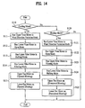
- a cooling mode (S110), as shown in FIGs. 12 and 14, the upper vane motor 38 runs in the wind direction variation mode, as in the air conditioner of the above-described embodiment. Accordingly, the upper vane 36 hinges continuously between the maximum open position C and the minimum open position D (S111). Meanwhile, the lower vane motor 48 runs in the open mode, thereby hingably rotating the lower vane 46 to the maximum open position C (S112).
- the upper filter motor 56 runs in the shifting mode, thereby maintaining the upper filter 52 in a state of being in contact with the upper stabilizer 32 (S113).
- the lower filter motor 66 runs in the filtering mode, to position the lower filter 62 such that the lower filter 62 is coupled to the lower vent 4 (S114).
- the upper and lower fan motors (not shown) run in the same direction, thereby causing the upper and lower blowing fans 174 and 184 to rotate in a normal direction (for example, a counterclockwise direction) (S115).
- the lower vane motor 48 runs in the wind direction variation mode, thereby swinging the lower vane 46 between the maximum open position C and the minimum open position D (S121).
- the upper vane motor 38 runs in the open mode, to position the upper vane 36 to the maximum open position C (S122).
- the upper filter motor 56 runs in the filtering mode, to position the upper filter 52 such that the upper filter 52 is coupled to the upper vent 2 (S123).
- the lower filter motor 66 runs in the shifting mode, to cause the lower filter 62 to come into contact with the lower stabilizer 42 (S124).
- the upper and lower fan motors (not shown) run in a reverse manner to that of the cooling mode. That is, the upper and lower blowing fans 174 and 184 are rotated in a reverse direction (for example, a clockwise direction) (S125).
- the upper and lower vane motors 38 and 48 it is also possible to configure the upper and lower vane motors 38 and 48 such that they can selectively run in the wind direction variation mode, and thus, to allow the user to select desired discharge characteristics.
- the discharge direction of hot/cold air is controlled to cause the hot air to be discharged out of a lower portion of the air conditioner during the heating operation such that the hot air uniformly heats a room while rising, thereby preventing the user from being uncomfortable, and to cause cold air to be discharged out of an upper portion of the air conditioner during the cooling operation such that the cold air reaches even a far region of the room while falling, thereby uniformly cooling the room.
Landscapes
- Engineering & Computer Science (AREA)
- Chemical & Material Sciences (AREA)
- Combustion & Propulsion (AREA)
- Mechanical Engineering (AREA)
- General Engineering & Computer Science (AREA)
- Air Conditioning Control Device (AREA)
- Air-Conditioning Room Units, And Self-Contained Units In General (AREA)
Abstract
Description
- The present invention relates to a method for controlling an air conditioner, and more particularly, to a method for controlling an air conditioner, which is capable of controlling a vent provided at the air conditioner to be selectively used as an air inlet for receiving indoor air or an air outlet for discharging the received air.
- Generally, air conditioners are used to cool or heat a confined space such as a room, in order to provide a comfortable indoor environment for users. Such an air conditioner includes a refrigerant cycle including a compressor, a 4-way valve, an outdoor heat exchanger (a condenser or evaporator), an expansion device, and an indoor heat exchanger (an evaporator or condenser). Air conditioners, which have such a configuration, are mainly classified into a separation type and an integrated type.
- Both the separation type air conditioner and the integrated type air conditioner have the same function. In the separation type air conditioner, however, an indoor unit, in which a cooling/heat-radiating device, an indoor fan, and an indoor fan motor are installed, and an outdoor unit, in which a heat-radiating/cooling device, a compressor, an outdoor fan, and an outdoor fan motor are installed, are separated from each other, and are connected to each other via a refrigerant line. On the other hand, in the integrated type air conditioner, indoor and outdoor units thereof are integrated so that cooling and heat-radiating functions are integrated. Such an integrated type air conditioner is directly installed on an outer wall or window of a house.
- An example of a conventional separation type air conditioner will be described with reference to FIGs. 1 and 2.
- The conventional air conditioner includes a
chassis 102, afront grill 110 coupled to a front wall of thechassis 102, aninlet grill 112 hingably connected to a front wall of thefront grill 110, and amotor 114 mounted to thechassis 102. The conventional air conditioner also includes a blowingfan 116 connected to themotor 114, and aheat exchanger 118 which heat-exchanges air introduced into the air conditioner with a refrigerant passing through theheat exchanger 118. - The
front grill 110 includes anair inlet 104 formed through the front wall of thefront grill 110. Anupper inlet grill 106 is provided at a top wall of thefront grill 110 such that theupper inlet grill 106 is integral with thefront grill 110. Anair outlet 108 is formed through a lower portion of the front wall of thefront grill 110 or through a bottom wall of thefront grill 110. - A pre-filter 105 is arranged inside the
front grill 110, to filter air introduced through theair inlet 104, and thus, to remove foreign matter from the air. - The
inlet grill 112 protects theair inlet 104 and pre-filter 105. Theinlet grill 112 is hingably connected to the top wall of thefront grill 110 at a top wall of theinlet grill 112. - A condensed
water receiver 119 is arranged at a lower portion of thefront grill 110 inside the front grill, to receive condensed water falling from theheat exchanger 118. Alouver 120 and anoutlet grill 124 are also arranged at a lower portion of thefront grill 110 inside thefront grill 110. Thelouver 120 changes the lateral flow direction of air discharged out of theair outlet 108. Theoutlet grill 124 includes avane 122 which changes the vertical flow direction of the discharged air. - When the blowing
fan 116 is rotated in accordance with driving of themotor 114 in the conventional air conditioner having the above-mentioned configuration, indoor air present in front of theinlet grill 112 is introduced into the air conditioner via theinlet grill 112 andair inlet 104. As the introduced air then passes through thefilter 105, foreign matter is removed from the air by thefilter 105. The filtered air is introduced into a space defined between thefront grill 110 and thechassis 102. - At the same time, indoor air present at the top side of the
front grill 110 is introduced into the space defined between thefront grill 110 and thechassis 102 via theupper inlet grill 106. - The introduced indoor air is cooled or heated by a refrigerant, which passes through the
indoor heat exchanger 118, while passing around theindoor heat exchanger 118. The cooled or heated air is discharged into a room, to be cooled or heated by the heat exchanger, in accordance with guidance of thelouver 120 andvane 122 after passing through the blowingfan 116. - However, the conventional air conditioner has a problem in that, where the installation level of the air conditioner is low, the time taken to uniformly spread throughout the room is lengthened because indoor air is discharged into the room through the lower side of the air conditioner after being introduced into the front and top sides of the air conditioner. On the other hand, where the installation level of the air conditioner is high, there is a problem in that increased uncomfortableness occurs during a heating operation because hot air is discharged toward the face of the user.
- An object of the present invention devised to solve the above-mentioned problems lies in providing a method for controlling an air conditioner, which is capable of reversely changing the introduction/discharge direction of air in accordance with a user's desire, thereby efficiently air-conditioning a room during a cooling/heating operation.
- Another object of the present invention is to provide a method for controlling an air conditioner, which is capable of controlling the discharge direction of hot/cold air, to cause the hot air to be discharged out of a lower portion of the air conditioner during a heating operation such that the hot air uniformly heats a room while rising, thereby preventing the user from being uncomfortable, and to cause the cold air to be discharged out of an upper portion of the air conditioner during a cooling operation such that the cold air reaches even a far region of the room while falling, thereby uniformly cooling the room.
- The objects of the present invention can be achieved by providing a method for controlling an air conditioner, comprising: an operation mode inputting step of selecting a cooling mode or a heating mode of the air conditioner, and inputting the selected operation mode; a cooling operation step of controlling a blowing unit by a controller when the operation mode selected at the operation mode inputting step is the cooling mode such that indoor air is discharged out of the air conditioner through a first vent after being sucked into the air conditioner through a second vent; and a heating operation step of controlling the blowing unit by the controller when the operation mode selected at the operation mode inputting step is the heating mode such that indoor air is discharged out of the air conditioner through the second vent after being sucked into the air conditioner through the first vent.
- In accordance with another aspect, the present invention provides a method for controlling an air conditioner including a body provided with a first vent and a second vent, through which introduction or discharge of air is selectively carried out, a cooling blower and a heating blower which are arranged in the body, to blow air in opposite directions, respectively, a heat exchanger which is arranged in the body, to cool or heat the blown air, a first vane which controls an opening degree of the first vent and a discharge direction of the air discharged through the first vent, a first vane motor which hingably rotates the first vane by a predetermined angle, a second vane which controls an opening degree of the second vent and a discharge direction of the air discharged through the second vent, a second vane motor which hingably rotates the second vane by a predetermined angle, and a controller which controls the cooling blower, the heating blower, and the first and second vane motors, the method comprising: an operation mode inputting step of selecting a cooling mode or a heating mode of the air conditioner, and inputting the selected operation mode; a cooling operation step of controlling the cooling blower by the controller when the operation mode selected at the operation mode inputting step is the cooling mode such that the cooling blower runs to suck indoor air through the second vent, and to discharge the sucked air through the first vent; and a heating operation step of controlling the heating blower by the controller when the operation mode selected at the operation mode inputting step is the heating mode such that the heating blower runs to suck the indoor air through the first vent, and to discharge the sucked air through the second vent.
- In accordance with another aspect, the present invention provides a method for controlling an air conditioner including a body provided with a first vent and a second vent, through which introduction or discharge of air is selectively carried out, a cooling blower and a heating blower which are arranged in the body, and can blow air while rotating in either a normal direction or a reverse direction, a heat exchanger which is arranged in the body, to cool or heat the blown air, a first vane which controls an opening degree of the first vent and a discharge direction of the air discharged through the first vent, a first vane motor which hingably rotates the first vane by a predetermined angle, a second vane which controls an opening degree of the second vent and a discharge direction of the air discharged through the second vent, a second vane motor which hingably rotates the second vane by a predetermined angle, and a controller which controls the first and second blowers and the first and second vane motors, the method comprising: an operation mode inputting step of selecting a cooling mode or a heating mode of the air conditioner, and inputting the selected operation mode; a cooling operation step of controlling the first and second blowers by the controller when the operation mode selected at the operation mode inputting step is the cooling mode such that the first and second blowers run to suck indoor air through the second vent, and to discharge the sucked air through the first vent; and a heating operation step of controlling the first and second blowers by the controller when the operation mode selected at the operation mode inputting step is the heating mode such that the first and second blowers run to suck the indoor air through the first vent, and to discharge the sucked air through the second vent.
- The invention also provides air conditioner apparatus adapted to put the above methods into effect.
- In accordance with the present invention, there are advantages in that it is possible to more efficiently air-condition a room during a cooling or heating operation, and thus, to provide enhanced comfortableness for users because the first vent or second vent is selected to discharge air in accordance with the cooling or heating mode of the air conditioner.
- The accompanying drawings, which are included to provide a further understanding of the invention, illustrate embodiments of the invention and together with the description serve to explain the principle of the invention.
- In the drawings:
- FIG. 1 is an exploded perspective view illustrating an example of a conventional air conditioner;
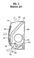
- FIG. 2 is a schematic sectional view illustrating a part of the air conditioner shown in FIG. 1;
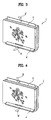
- FIG. 3 is a schematic perspective view of an air conditioner according to an exemplary embodiment of the present invention, illustrating a cooling operation of the air conditioner;
- FIG. 4 is a schematic perspective view of the air conditioner shown in FIG. 3, illustrating a heating operation of the air conditioner;
- FIG. 5 is an exploded perspective view illustrating an inner configuration of the air conditioner shown in FIG. 3;
- FIG. 6 is a schematic sectional view of a part of the air conditioner shown in FIG. 3, illustrating a cooling operation of the air conditioner;
- FIG. 7 is a schematic sectional view of a part of the air conditioner shown in FIG. 3, illustrating a heating operation of the air conditioner;
- FIG. 8 is a block diagram illustrating a configuration for controlling the air conditioner shown in FIG. 3;
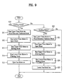
- FIG. 9 is a flow chart explaining an air conditioner control method according to a first embodiment of the present invention;
- FIG. 10 is a flow chart explaining an air conditioner control method according to a second embodiment of the present invention, in particular, a cooling mode control procedure thereof;
- FIG. 11 is a flow chart explaining the air conditioner control method of FIG. 10, in particular, a heating mode control procedure thereof;
- FIG. 12 is a schematic sectional view of a part of an air conditioner according to another embodiment of the present invention, illustrating a cooling operation of the air conditioner;
- FIG. 13 is a schematic sectional view of a part of the air conditioner shown in FIG. 12, illustrating a heating operation of the air conditioner; and
- FIG. 14 is a flow chart explaining a method for controlling the air conditioner of FIGs. 12 and 13 in accordance with an exemplary embodiment of the present invention.
- Reference will now be made in detail to the preferred embodiments of the present invention, examples of which are illustrated in the accompanying drawings.
- An exemplary configuration of an air conditioner, to which an air conditioner controlling method according to the present invention is applied, will be described with reference to FIGs. 3 to 8.
- In accordance with the present invention, the air conditioner has a configuration in which air A is introduced into a lower portion of the air conditioner during a cooling operation, and is then discharged out of an upper portion of the air conditioner after heat-exchanging with a refrigerant, as shown in FIG. 3, whereas air B is introduced into the upper portion of the air conditioner during a heating operation, and is then discharged out of the lower portion of the air conditioner after heat-exchanging with the refrigerant, as shown in FIG. 4.
- That is, in the
air conditioner 1, air is introduced into theair conditioner 1 through alower vent 4 during a cooling operation, and is then discharged out of the air conditioner through anupper vent 2 after being cooled. On the other hand, air is introduced into the air conditioner through theupper vent 2 during a heating operation, and is then discharged out of the air conditioner through thelower vent 4 after being heated. - The configuration of the air conditioner will be described in more detail with reference to FIGs. 5 to 8.
- As shown in FIGs. 5 and 6, the
upper vent 2 andlower vent 4 are formed through top and bottom walls of abody 10 of the air conditioner, respectively, to receive or discharge air. A blowingunit 70 is arranged in thebody 10. The blowingunit 70 sucks indoor air through one of the upper andlower vents lower vents - An air guide passage P is defined in the
body 10 such that the air guide passage P extends vertically. - The
body 10 includes amain chassis 12, and afront panel assembly 20 which covers the overall surface of themain chassis 12. Thebody 10 also includes an upper inlet/outlet unit 30 which is arranged at an upper portion of themain chassis 12, to control a flow of air flowing through theupper vent 2, and a lower inlet/outlet unit 40 which is arranged at a lower portion of themain chassis 12, to control a flow of air flowing through thelower vent 4. - The
main chassis 12 is mounted to a wall of a room, to be air-conditioned by the air conditioner, by a supporter (not shown) fixed to the room wall. - An
upper air guide 14 and alower air guide 15 are formed at themain chassis 12, to define the air guide passage P which guides air passing between themain chassis 12 and thefront panel assembly 20. - Preferably, the
upper air guide 14 has a round surface so that it forms a scroll housing of an upper blowingfan 74 as will be described hereinafter. Similarly, thelower air guide 14 preferably has a round surface so that it forms a scroll housing of alower blowing fan 84 as will be described hereinafter. - A
heat exchanger 18 is arranged between themain chassis 12 and thefront panel assembly 20. - In the illustrated embodiment, the
heat exchanger 18 is arranged between the front side of the upper blowingfan 74 and the upper side of thelower blowing fan 84. Also, theheat exchanger 18 is arranged such that the top of theheat exchanger 18 is adjacent to the front wall of thebody 10, and the bottom of theheat exchanger 18 is adjacent to the bottom of theupper air guide 14. That is, theheat exchanger 18 is arranged across the air guide passage P. - A
condensed water receiver 19 is formed at themain chassis 12 such that thecondensed water receiver 19 is downwardly protruded from a lower end of themain chassis 12. Thecondensed water receiver 19 is arranged beneath a rear end of theheat exchanger 18, to receive condensed water falling from theheat exchanger 18. - Upper
lateral barriers main chassis 12 at opposite sides of themain chassis 12, respectively. The upperlateral barriers fan 74 received in theupper air guide 14 at opposite sides of theupper air guide 14, and to prevent air blown by the upper blowingfan 74 from being laterally leaked. - One of the upper
lateral barriers lateral barrier 14A, has abearing mount 14D to which anupper bearing 74c for rotatably supporting the upper blowingfan 74 is mounted. The other upperlateral barrier 14B has an axial throughhole 14E through which arotating shaft 76a of anupper fan motor 76 extends. - An
upper supporter 14F is fastened to the upperlateral barrier 14A having thebearing mount 14D by means of screws. Theupper supporter 14F functions to receive theupper bearing 74c, and thus, to rotatably support the upper blowingfan 74 together with the upperlateral barrier 14A. Theupper supporter 14F also functions to prevent air blown by the upper blowingfan 74 from being laterally leaked. - Lower lateral barriers 15A and 15B are protruded from the lower portion of the
main chassis 12 at opposite sides of themain chassis 12, respectively. The lower lateral barriers 15A and 15B function to support thelower blowing fan 84 received in thelower air guide 15 at opposite sides of thelower air guide 15, and to prevent air blown by thelower blowing fan 84 from being laterally leaked. - One of the lower lateral barriers 15A and 15B, namely, the lower lateral barrier 15A, has a bearing mount 15D to which a
lower bearing 84c for rotatably supporting thelower blowing fan 84 is mounted. The other lower lateral barrier 15B has an axial throughhole 15E through which arotating shaft 86a of alower fan motor 86 extends. - A
lower supporter 15F is fastened to the lower lateral barrier 15A having the bearing mount 15D by means of screws. Thelower supporter 15F functions to receive thelower bearing 84c, and thus, to rotatably support thelower blowing fan 84 together with the lower lateral barrier 15A. Thelower supporter 15F also functions to prevent air blown by thelower blowing fan 84 from being laterally leaked. - The
upper supporter 14F andlower supporter 15F also function to firmly support the upper and lower portions of theheat exchanger 18 at one side of theheat exchanger 18, respectively. - The blowing
unit 70 includes constituent elements respectively arranged at the upper and lower portion of thebody 10 inside thebody 10. - That is, the blowing
unit 70 includes a cooling blower 72 arranged at the upper portion of thebody 10 inside thebody 10, and aheating blower 82 arranged at the lower portion of thebody 10 inside thebody 10. - During a cooling operation, the cooling blower 72 sucks indoor air A via the lower inlet/
outlet unit 40, and discharges the indoor air A via the upper inlet/outlet unit 30 after causing the indoor air A to pass through theheat exchanger 18. On the other hand, during a heating operation, theheating blower 82 sucks indoor air B via the upper inlet/outlet unit 30, and discharges the indoor air B via the lower inlet/outlet unit 40 after causing the indoor air B to pass through theheat exchanger 18. - The cooling blower 72 includes the upper blowing
fan 74 andupper fan motor 76. The upper blowingfan 74 is arranged at the upper portion of thebody 10 inside thebody 10 such that the upper blowingfan 74 extends laterally. Theupper fan motor 76 is mounted to themain chassis 12 such that theupper fan motor 76 is arranged at one side of the upper blowingfan 74, to rotate the upper blowingfan 74. In particular, theupper fan motor 76 is mounted to anupper motor mount 12a formed at one side of themain chassis 12. - In the illustrated embodiment, the upper blowing
fan 74 is a cross flow fan which has blades adapted to upwardly blow air. - The upper blowing
fan 74 includes a leftrotating shaft 74a which is protruded from a left end of the upper blowingfan 74, and is coupled to theupper bearing 74c such that the leftrotating shaft 74a is rotatably supported by theupper bearing 74c. The upper blowingfan 74 also includes a rightrotating shaft 74b which is protruded from a right end of the upper blowingfan 74, and is coupled to therotating shaft 76a of theupper fan motor 76 through the axial throughhole 14E, to receive a rotating force from therotating shaft 76a. - The
upper fan motor 76 rotates the upper blowingfan 74 during the cooling operation of the air conditioner, and stops the upper blowingfan 74 during the heating operation of the air conditioner. - The
heating blower 82 includes thelower blowing fan 84 andlower fan motor 86. Thelower blowing fan 84 is arranged at the lower portion of thebody 10 inside thebody 10 such that thelower blowing fan 84 extends laterally while being parallel to the upper blowingfan 74. Thelower fan motor 86 is mounted to themain chassis 12 such that thelower fan motor 86 is arranged at one side of thelower blowing fan 84, to rotate thelower blowing fan 84. In particular, thelower fan motor 86 is mounted to alower motor mount 12b formed at one side of themain chassis 12. - In the illustrated embodiment, similarly to the upper blowing
fan 74, thelower blowing fan 84 is a cross flow fan which has blades adapted to downwardly blow air. - The
lower blowing fan 84 includes a leftrotating shaft 84a which is protruded from a left end of thelower blowing fan 84, and is coupled to thelower bearing 84c such that the leftrotating shaft 84a is rotatably supported by thelower bearing 84c. Thelower blowing fan 84 also includes a rightrotating shaft 84b which is protruded from a right end of thelower blowing fan 84, and is coupled to therotating shaft 86a of thelower fan motor 86 through the axial throughhole 15E, to receive a rotating force from therotating shaft 86a. - The
lower fan motor 86 stops thelower blowing fan 84 during the cooling operation of the air conditioner, and rotates thelower blowing fan 84 during the heating operation of the air conditioner. - In the illustrated embodiment, the
upper fan motor 76 andlower fan motor 86 are vertically arranged at the left or right side of thebody 10 inside thebody 10, taking connection of electric wires into consideration. Alternatively, thefan motors fan motors - Where the
upper fan motor 76 andlower fan motor 86 are vertically arranged at the right side of thebody 10 inside thebody 10, theupper fan motor 76 andlower fan motor 86 rotate the upper blowingfan 74 andlower blowing fan 84 in opposite directions, respectively, such that, when the upper blowingfan 74 is rotated in a clockwise direction, thelower blowing fan 74 is rotated in a counterclockwise direction. - Meanwhile, a
control box 99 is arranged at one side of the body 10 (the right side in the illustrated embodiment). Thecontrol box 99 contains electric elements for controlling operations of theupper fan motor 76 andlower fan motor 86 in accordance with a cooling/heating mode of the air conditioner. - The
control box 99 is connected to theupper fan motor 76 andlower fan motor 86 viaelectric wires control box 99 is fixed to one of themain chassis 12 andfront panel assembly 20 such that thecontrol box 99 is arranged between themain chassis 12 and thefront panel assembly 20. - The
control box 99 may be arranged such that it covers the front sides of theupper fan motor 76 andlower fan motor 86. Alternatively, thecontrol box 99 may be arranged such that it is interposed between theupper motor mount 12a and thelower motor mount 12b. - Meanwhile, the
front panel assembly 20 defines the air guide passage P, together with themain chassis 12. Thefront panel assembly 20 includes afront case 22 which is open at the front side thereof, and afront panel 24 which is coupled to the front side of thefront case 22, to close the front side of thefront case 22. - The
front panel 24 may be separably coupled to the front side of thefront case 22. Alternatively, thefront panel 24 may be integrated with the front side of thefront case 22. - A particular picture, photograph, design, or color may be printed on the
front panel 24. Thefront panel 24 is provided, at a particular portion thereof, with atransparent window 24a. Adisplay device 24b may be mounted to thefront panel 24 at the rear of thetransparent window 24a, to display various information of the air conditioner. Thedisplay device 24b may be a light emitting diode (LED), a liquid crystal display (LCD), an organic electroluminescent (EL) display, or the like. - Although the
front panel 24 is configured to have thedisplay device 24b at a lower portion of thefront panel 24 in the illustrated embodiment, the entire portion of thefront panel 24 may be constituted by a display device. - Alternatively, the
front panel 24 may be configured in the form of a picture frame such that a photograph is put in thefront panel 24. - The upper inlet/
outlet unit 30 includes anupper stabilizer 32, at which theupper vent 2 is formed, anupper vane 36 which controls the flow direction of air passing through theupper vent 2, and anupper vane motor 38 which hingably rotates theupper vane 36 by a desired angle. - As shown in FIG. 6, the
upper vane motor 38 hingably rotates theupper vane 36 between a maximum open position C and a minimum open position D during the cooling operation, to control the flow direction and range of air A' discharged through theupper vent 2. Here, the "flow direction of air" will also be simply referred to as "wind direction". This mode is referred to as a "wind direction variation mode of the vane". - During the cooling operation, the
upper vane motor 38 fixes the upper vane 37 at the maximum open position C, as shown in FIG. 7, in order to enable a maximum amount of indoor air B to be introduced into the air conditioner through theupper vent 2. This mode is referred to as an "open mode of the vane". - When the air conditioner does not operate, the
upper vane motor 38 hingably rotates theupper vane 36 to a closed position E, in order to close theupper vent 2. This mode is referred to as a "close mode of the vane". - The lower inlet/
outlet unit 40 includes alower stabilizer 42, at which thecondensed water receiver 41 for receiving condensed water falling from theheat exchanger 18 is formed, together with thelower vent 4. The lower inlet/outlet unit 40 also includes alower vane 46 which controls the flow direction of air passing through thelower vent 4, and alower vane motor 48 which hingably rotates thelower vane 46 by a desired angle. - The
lower vane motor 48 operates thelower vane 46 in an "open mode". That is, thelower vane motor 48 fixes thelower vane 46 at the maximum open position C during the cooling operation, as shown in FIG. 6, to allow thelower vane 46 to guide indoor air A such that a maximum amount of indoor air A is sucked into the air conditioner through thelower vent 4. - As shown in FIG. 7, the
lower vane motor 48 hingably rotates thelower vane 46 between the maximum open position C and a minimum open position D during the heating operation, to control the flow direction and range of air B discharged through thelower vent 4. That is, thelower vane motor 48 operates in a "wind direction variation mode" during the heating operation of the heat exchanger. - When the air conditioner does not operate, the
lower vane motor 48 hingably rotates thelower vane 46 to a closed position E, in order to close thelower vent 4. - In accordance with the present invention, the air conditioner further includes an
upper filter unit 50 which filters air passing through theupper vent 2, and alower filter unit 60 which filters air passing through thelower vent 4. - The
upper filter unit 50 includes anupper filter 52 which filters air B introduced into theupper vent 2, to remove foreign matter from the introduced air B, anupper filter holder 54 which separably holds theupper filter 52, and is hingably mounted to theupper vent 2, and anupper filter motor 56 which hingably rotates theupper filter holder 54 by a desired angle. Theupper filter motor 56 is mounted to the upper inlet/outlet unit 30. - During the cooling operation of the air conditioner, the
upper filter motor 56 hingably rotates theupper filter holder 54 such that theupper filter 52 approximately comes into contact with theupper stabilizer 32, thereby causing theupper vent 2 to be completely opened (this mode is referred to as a "shifting mode"), as shown in FIG. 6. On the other hand, during the heating operation of the air conditioner, theupper filter motor 56 hingably rotates theupper filter holder 54 such that theupper filter 52 is coupled to the upper vent 2 (this mode is referred to as a "filtering mode"), as shown in FIG. 7. - The
lower filter unit 60 includes alower filter 62 which filters air A introduced into thelower vent 4, to remove foreign matter from the introduced air A, alower filter holder 64 which separably holds thelower filter 62, and is hingably mounted to thelower vent 4, and alower filter motor 66 which hingably rotates thelower filter holder 64 by a desired angle. Thelower filter motor 66 is mounted to the lower inlet/outlet unit 40. - During the cooling operation of the air conditioner, the
lower filter motor 66 hingably rotates thelower filter holder 64 such that thelower filter 62 is coupled to thelower vent 4, as shown in FIG. 6. On the other hand, during the heating operation of the air conditioner, thelower filter motor 66 hingably rotates thelower filter holder 64 such that thelower filter 62 approximately comes into contact with thelower stabilizer 42, thereby causing thelower vent 4 to be completely opened, as shown in FIG. 7. - FIG. 8 is a block diagram illustrating a configuration for controlling the air conditioner having the above-described configuration. In accordance with the illustrated embodiment, the air conditioner includes an
input part 94 which inputs a signal for selection of the cooling or heating operation of the heat exchanger. Theinput part 94 is connected to acontroller 97 which not only controls theupper vane motor 38,lower vane motor 48,upper filter motor 56,lower filter motor 66,upper fan motor 76, andlower fan motor 86, but also controls acompressor 95 and anoutdoor fan motor 96. Thecompressor 95 andoutdoor fan motor 96 constitute an outdoor unit. Accordingly, when a cooling or heating mode is selected through theinput part 94, thecontroller 97 not only controls operations of theupper vane motor 38,lower vane motor 48,upper filter motor 56,lower filter motor 66,upper fan motor 76, andlower fan motor 86, but also controls operations of thecompressor 95 andoutdoor fan motor 96, to cause the selected operation mode to be executed. - The
input part 94 may be built in one side of the air conditioner. Alternatively, theinput part 94 may be configured in the form of a remote controller. - A method for controlling the air conditioner having the above-described configuration in accordance with a first embodiment of the present invention will be described in detail with reference to FIGs. 6, 7, and 9.
- The control method will be described in conjunction with the cooling operation of the air conditioner with reference to FIGs. 6 and 9.
- When the user enters a signal for selection of a cooling mode through the input part 94 (FIG. 8), to initiate the cooling mode (S10), the
upper vane motor 38 runs in the wind direction variation mode, thereby continuously hingably rotating theupper vane 36 between the maximum open position C and the minimum open position D (S11). Meanwhile, thelower vane motor 48 runs in the open mode, thereby hingably rotating thelower vane 46 to the maximum open position C (S12). - Also, the
upper filter motor 56 runs in the shifting mode, to maintain theupper filter 52 in a state of being in contact with the upper stabilizer 32 (S13). At the same time, thelower filter motor 66 runs in the filtering mode, to hingably rotate thelower filter holder 64 such that thelower filter 62 is coupled to the lower vent 4 (S14). - Subsequently, the
upper fan motor 76 runs to rotate the upper blowing fan 74 (S15). - In accordance with the rotation of the
upper fan motor 76, indoor air A is sucked into the air conditioner through thelower vent 4, to flow upwardly in the air conditioner. The air sucked through thelower vent 4 is filtered by thelower filter 62, to remove foreign matter such as dust from the sucked air. The filtered air then flows along the air guide passage P defined between themain chassis 12 and thefront panel assembly 20. - The air flowing through the air guide passage P heat-exchanges with the refrigerant passing through the
heat exchanger 18, while passing around theheat exchanger 18. Thereafter, the air is upwardly blown after passing through the upper blowingfan 74. - The air, which emerges from the upper blowing
fan 74 after being cooled by theheat exchanger 18, namely, cold air A', is discharged to an upper portion of the room via theupper vent 2. - The cold air A', which is discharged out of the front upper portion of the air conditioner in the above-described manner, falls just like shower while being widely spread over the upper portion of the room. Thus, the cold air A' reaches even a far region of the room, thereby uniformly cooling the entire portion of the room.
- When the operation of the air conditioner is stopped, the
upper vane motor 38 andlower vane motor 48 hingably rotate theupper vane 36 andlower vane 46 to the closed positions E thereof, to close the upper andlower vents - Next, the control method will be described in conjunction with the heating operation of the air conditioner with reference to FIGs. 7 and 9.
- The heating operation of the air conditioner is carried out in a reverse manner to the above-described cooling operation.
- That is, when a heating mode is selected (S20), the
lower vane motor 48 runs in the wind direction variation mode, thereby hingably rotating thelower vane 46 between the maximum open position C and the minimum open position D (S21). Meanwhile, theupper vane motor 38 runs in the open mode, to hingably rotate theupper vane 36 to the maximum open position C, and then stops theupper vane 36 at the maximum open position C (S22). - Also, the
upper filter motor 56 runs in the filtering mode, to hingably rotate theupper filter holder 54 such that theupper filter 52 is coupled to the upper vent 2 (S23). At the same time, thelower filter motor 66 runs in the shifting mode, to cause thelower filter 62 to come into contact with the lower stabilizer 42 (S24). - Subsequently, the
lower fan motor 86 runs to rotate thelower blowing fan 84 in a state in which the upper blowingfan 74 is stopped (S25). - In accordance with the rotation of the
lower fan motor 86, indoor air B is sucked into the air conditioner through theupper vent 2, to flow downwardly in the air conditioner. The air sucked through theupper vent 2 is filtered by theupper filter 62, to remove foreign matter such as dust from the sucked air. The filtered air then flows along the air guide passage P defined between themain chassis 12 and thefront panel assembly 20. - The air flowing through the air guide passage P heat-exchanges with the refrigerant passing through the
heat exchanger 18, while passing around theheat exchanger 18. As a result, the air is heated. Thereafter, the heated air is downwardly blown after passing through thelower blowing fan 84. - The air, which emerges from the
lower blowing fan 84, namely, hot air B', is discharged to a lower portion of the room via thelower vent 4. In this case, as described above, thelower vane motor 48 controls the discharge direction of the hot air B' by continuously hingably rotating thelower vane 46 between the maximum open position C and the minimum open position D. - The hot air B', which is discharged out of the front lower portion of the air conditioner in the above-described manner, rises upwardly after being widely spread over the lower portion of the room. Thus, the hot air B' reaches even a far region of the room, thereby uniformly heating the entire portion of the room.
- When the operation of the air conditioner is stopped, the
upper vane motor 38 andlower vane motor 48 hingably rotate theupper vane 36 andlower vane 46 to the closed positions E thereof, to close the upper andlower vents - Thus, the air conditioner of the preset invention is characterized in that each of the
upper vent 2 andlower vent 4 selectively functions as an inlet or outlet in accordance with the operation mode, to discharge cold air or hot air in a direction desired by the user. - Meanwhile, in accordance with the air conditioner control method of the above-described embodiment, the controller 95 (FIG. 8) controls the
upper vane motor 38 andlower vane motor 48 to run in the wind direction variation mode in a forced manner. - However, the
vane motors - This will be described in detail with reference to FIGs. 10 and 11.
- When the user or controller 95 (FIG. 8) selects a cooling mode for the cooling operation (S10), and selects the wind direction variation mode at the wind direction variation mode selecting step S10A, as shown in FIG. 10, the same procedure as that of the above-described embodiment is executed.
- That is, the
upper vane motor 38 runs in the wind direction variation mode, to swing theupper vane 36 between the maximum open position C and the minimum open position D (S11). On the other hand, thelower vane motor 48 runs in the open mode, to hingably rotate thelower vane 46 to the maximum open position C (S12). - The
upper filter motor 56 runs in the shifting mode, to maintain theupper filter 52 in a state of being in contact with the upper stabilizer 32 (S13). Also, thelower filter motor 66 runs in the filtering mode, to position thelower filter 62 such that thelower filter 62 is coupled to the lower vent 4 (S14). - Subsequently, the
upper fan motor 76 runs to rotate the upper blowing fan 74 (S15). - In accordance with the rotation of the
upper fan motor 76, air flows upwardly in the air conditioner. Accordingly, cold air A' is discharged through theupper vent 2, while being varied in discharge direction by theupper vane 36. - On the other hand, when the wind direction variation mode is not selected at the wind direction variation mode selecting step S10A, the
upper vane motor 38 runs in the open mode, to hingably rotate theupper vane 36 to the maximum open position C, and then stops theupper vane 36 at the maximum open position C such that theupper vane 36 is maintained at the maximum open position C (S11a). - In this case, the operations (S12a to S15a) of the
lower vane motor 48, upper andlower filter motors upper fan motor 76 are identical to the operations (S12 to S15) in the wind direction variation mode. - Accordingly, when the wind direction variation mode is not selected in the cooling mode (S10), cold air A' is discharged out of the
upper vent 2 under the condition in which theupper vane 36 is fully opened. - The above-described conditions are equally given in the heating mode.
- That is, when the wind direction variation mode is selected at the wind direction variation mode selecting step S20A during a heating mode (S20), the
lower vane 46 is swung between the maximum open position C and the minimum open position D by thelower vane motor 48, to control the discharge direction of hot air (S21 to S25). - On the other hand, when the wind direction variation mode is not selected, hot air is discharged under the condition in which the
lower vane 46 is maintained at the maximum open position C by the lower vane motor 48 (S21a to S25a). - Meanwhile, the air conditioner according to the above-described embodiment is configured such that the
vents body 10, to discharge conditioned air out of the upper or lower sides of the air conditioner. However, vents may be formed at the left and right sides of the air conditioner, respectively, such that they are opposed to each other. In this case, in accordance with a cooling or heating mode, air may be introduced into the right side of the air conditioner, and may be discharged out of the left side of the air conditioner. Otherwise, air may be introduced into the left side of the air conditioner, and may be discharged out of the right side of the air conditioner. - The air conditioner of the latter case has a structure identical to the 90°-rotated structure of the air conditioner according to the above-described embodiment. Accordingly, no detailed description will be given of the latter air conditioner.
- In accordance with the air conditioner control method according to the above-described embodiment, the cooling fan 72 operates only in the cooling mode, to blow air, whereas the
heating fan 82 operates only in the heating mode, to blow air. - However, where each of the upper and lower blowing fans has a structure capable of generating wind in substantially-equal amounts, but in opposite wind directions, when the associated blowing fan rotates in normal and reverse directions, respectively, it is possible to blow air using both the blowing fans in the cooling or heating mode.
- An air conditioner, to which such blowing fans are applied, and a method for controlling the air conditioner will be described with reference to FIGs. 12 to 14.
- As shown in FIGs. 12 and 13, the air conditioner according to this embodiment has the same configuration as that of the above-described air conditioner, except for upper and lower blowing
fans - Each of the upper and lower blowing
fans fans - The air conditioner having the above-described configuration is controlled as follows.
- In a cooling mode (S110), as shown in FIGs. 12 and 14, the
upper vane motor 38 runs in the wind direction variation mode, as in the air conditioner of the above-described embodiment. Accordingly, theupper vane 36 hinges continuously between the maximum open position C and the minimum open position D (S111). Meanwhile, thelower vane motor 48 runs in the open mode, thereby hingably rotating thelower vane 46 to the maximum open position C (S112). - Also, the
upper filter motor 56 runs in the shifting mode, thereby maintaining theupper filter 52 in a state of being in contact with the upper stabilizer 32 (S113). At the same time, thelower filter motor 66 runs in the filtering mode, to position thelower filter 62 such that thelower filter 62 is coupled to the lower vent 4 (S114). - Subsequently, the upper and lower fan motors (not shown) run in the same direction, thereby causing the upper and lower blowing
fans - In accordance with the rotation of the upper and lower blowing
fans upper vent 2 which is arranged at the upper portion of the air conditioner. - On the other hand, in a heating mode (S120), as shown in FIGs. 13 and 14, the
lower vane motor 48 runs in the wind direction variation mode, thereby swinging thelower vane 46 between the maximum open position C and the minimum open position D (S121). Meanwhile, theupper vane motor 38 runs in the open mode, to position theupper vane 36 to the maximum open position C (S122). Theupper filter motor 56 runs in the filtering mode, to position theupper filter 52 such that theupper filter 52 is coupled to the upper vent 2 (S123). At the same time, thelower filter motor 66 runs in the shifting mode, to cause thelower filter 62 to come into contact with the lower stabilizer 42 (S124). - In this state, the upper and lower fan motors (not shown) run in a reverse manner to that of the cooling mode. That is, the upper and lower blowing
fans - In accordance with the rotation of the upper and lower blowing
fans lower vent 4. - Of course, in the air conditioner of this embodiment, it is also possible to configure the upper and
lower vane motors - As apparent from the above description, in accordance with the air conditioner control method of the present invention, there is an advantage in that it is possible to more efficiently air-condition a room during cooling and heating operations because the discharge direction of air can be varied depending on the cooling and heating modes.
- In particular, in accordance with the present invention, the discharge direction of hot/cold air is controlled to cause the hot air to be discharged out of a lower portion of the air conditioner during the heating operation such that the hot air uniformly heats a room while rising, thereby preventing the user from being uncomfortable, and to cause cold air to be discharged out of an upper portion of the air conditioner during the cooling operation such that the cold air reaches even a far region of the room while falling, thereby uniformly cooling the room.
- It will be apparent to those skilled in the art that various modifications and variations can be made in the present invention without departing from the scope of the invention. Thus, it is intended that the present invention cover the modifications and variations of the embodiments provided they come within the scope of the appended claims.
Claims (20)
- A method for controlling an air conditioner, comprising:an operation mode inputting step of selecting a cooling mode or a heating mode of the air conditioner, and inputting the selected operation mode;a cooling operation step of controlling a blowing unit by a controller when the operation mode selected at the operation mode inputting step is the cooling mode such that indoor air is discharged out of the air conditioner through a first vent after being sucked into the air conditioner through a second vent; anda heating operation step of controlling the blowing unit by the controller when the operation mode selected at the operation mode inputting step is the heating mode such that indoor air is discharged out of the air conditioner through the second vent after being sucked into the air conditioner through the first vent.
- The method according to claim 1, wherein:the blowing unit includes a cooling blower and a heating blower which blow air in opposite directions, respectively;the controller controls, at the cooling operation step, the cooling blower to run such that the cooling blower sucks the indoor air through the second vent, and discharges the sucked air through the first vent; andthe controller controls, at the heating operation step, the heating blower to run such that the cooling blower sucks the indoor air through the first vent, and discharges the sucked air through the second vent.
- The method according to claim 1, wherein:the blowing unit includes a first blower and a second blower which can blow air while rotating in either a normal direction or a reverse direction;the controller controls, at the cooling operation step, the first and second blowers to rotate simultaneously in the normal direction such that the first and second blowers suck the indoor air through the second vent, and discharge the sucked air through the first vent; andthe controller controls, at the heating operation step, the first and second blowers to rotate simultaneously in the reverse direction such that the first and second blowers suck the indoor air through the first vent, and discharge the sucked air through the second vent.
- The method according to claim 1, wherein a wind direction variation mode is additionally executed at the cooling operation step, to vary a discharge direction of the air discharged through the first vent.
- The method according to claim 4, wherein the wind direction variation mode is selected at the operation mode inputting step.
- The method according to claim 1, wherein a wind direction variation mode is additionally executed at the heating operation step, to vary a discharge direction of the air discharged through the second vent.
- The method according to claim 6, wherein the wind direction variation mode is selected at the operation mode inputting step.
- The method according to claim 1, wherein a filtering mode is additionally executed at the cooling and heating operation steps, to remove foreign matter from the air sucked through the second vent and the air sucked through the first vent.
- A method for controlling an air conditioner including a body provided with a first vent and a second vent, through which introduction or discharge of air is selectively carried out, a cooling blower and a heating blower which are arranged in the body, to blow air in opposite directions, respectively, a heat exchanger which is arranged in the body, to cool or heat the blown air, a first vane which controls an opening degree of the first vent and a discharge direction of the air discharged through the first vent, a first vane motor which hingably rotates the first vane by a predetermined angle, a second vane which controls an opening degree of the second vent and a discharge direction of the air discharged through the second vent, a second vane motor which hingably rotates the second vane by a predetermined angle, and a controller which controls the cooling blower, the heating blower, and the first and second vane motors, the method comprising:an operation mode inputting step of selecting a cooling mode or a heating mode of the air conditioner, and inputting the selected operation mode;a cooling operation step of controlling the cooling blower by the controller when the operation mode selected at the operation mode inputting step is the cooling mode such that the cooling blower runs to suck indoor air through the second vent, and to discharge the sucked air through the first vent; anda heating operation step of controlling the heating blower by the controller when the operation mode selected at the operation mode inputting step is the heating mode such that the heating blower runs to suck the indoor air through the first vent, and to discharge the sucked air through the second vent.
- The method according to claim 9, wherein, at the cooling operation step, the first vane motor runs to hingably rotate the first vane to a maximum open position, and maintains the first vane at the maximum open position.
- The method according to claim 9, wherein, at the cooling operation step, the first vane motor runs to swing the first vane within a predetermined angle range such that a discharge direction of cold air discharged out of the first vent is varied.
- The method according to claim 9, wherein, at the heating operation step, the second vane motor runs to hingably rotate the second vane to a maximum open position, and maintains the second vane at the maximum open position.
- The method according to claim 9, wherein, at the heating operation step, the second vane motor runs to swing the second vane within a predetermined angle range such that a discharge direction of hot air discharged out of the second vent is varied.
- The method according to claim 9, wherein a filtering step is additionally executed at the cooling and heating operation steps, to selectively position a filter at the first vent or at the second vent such that foreign matter is removed from the air sucked through the second vent and the air sucked through the first vent.
- A method for controlling an air conditioner including a body provided with a first vent and a second vent, through which introduction or discharge of air is selectively carried out, a cooling blower and a heating blower which are arranged in the body, and can blow air while rotating in either a normal direction or a reverse direction, a heat exchanger which is arranged in the body, to cool or heat the blown air, a first vane which controls an opening degree of the first vent and a discharge direction of the air discharged through the first vent, a first vane motor which hingably rotates the first vane by a predetermined angle, a second vane which controls an opening degree of the second vent and a discharge direction of the air discharged through the second vent, a second vane motor which hingably rotates the second vane by a predetermined angle, and a controller which controls the first and second blowers and the first and second vane motors, the method comprising:an operation mode inputting step of selecting a cooling mode or a heating mode of the air conditioner, and inputting the selected operation mode;a cooling operation step of controlling the first and second blowers by the controller when the operation mode selected at the operation mode inputting step is the cooling mode such that the first and second blowers run to suck indoor air through the second vent, and to discharge the sucked air through the first vent; anda heating operation step of controlling the first and second blowers by the controller when the operation mode selected at the operation mode inputting step is the heating mode such that the first and second blowers run to suck the indoor air through the first vent, and to discharge the sucked air through the second vent.
- The method according to claim 15, wherein, at the cooling operation step, the first vane motor runs to hingably rotate the first vane to a maximum open position, and maintains the first vane at the maximum open position.
- The method according to claim 15, wherein, at the cooling operation step, the first vane motor runs to swing the first vane within a predetermined angle range such that a discharge direction of cold air discharged out of the first vent is varied.
- The method according to claim 15, wherein, at the heating operation step, the second vane motor runs to hingably rotate the second vane to a maximum open position, and maintains the second vane at the maximum open position.
- The method according to claim 15, wherein, at the heating operation step, the second vane motor runs to swing the second vane within a predetermined angle range such that a discharge direction of hot air discharged out of the second vent is varied.
- The method according to claim 15, wherein a filtering step is additionally executed at the cooling and heating operation steps, to selectively position a filter at the first vent or at the second vent such that foreign matter is removed from the air sucked through the second vent and the air sucked through the first vent.
Applications Claiming Priority (2)
| Application Number | Priority Date | Filing Date | Title |
|---|---|---|---|
| KR1020050042762A KR101155480B1 (en) | 2005-05-21 | 2005-05-21 | Air conditioner and Discharge direction control method of the same |
| KR1020050044089A KR20060122098A (en) | 2005-05-25 | 2005-05-25 | Air conditioner |
Publications (1)
| Publication Number | Publication Date |
|---|---|
| EP1726889A1 true EP1726889A1 (en) | 2006-11-29 |
Family
ID=36809517
Family Applications (1)
| Application Number | Title | Priority Date | Filing Date |
|---|---|---|---|
| EP06252456A Withdrawn EP1726889A1 (en) | 2005-05-21 | 2006-05-10 | Method for controlling an air conditioning unit |
Country Status (3)
| Country | Link |
|---|---|
| EP (1) | EP1726889A1 (en) |
| AU (1) | AU2006250250B2 (en) |
| WO (1) | WO2006126807A2 (en) |
Cited By (8)
| Publication number | Priority date | Publication date | Assignee | Title |
|---|---|---|---|---|
| CN102042655A (en) * | 2009-10-16 | 2011-05-04 | 海信(山东)空调有限公司 | Touch display screen of air conditioner |
| CN103375882A (en) * | 2012-04-27 | 2013-10-30 | 富士通将军股份有限公司 | Controller circuit for air conditioner and computer-readable storage medium containing program instructions for controlling air conditioner |
| EP2169320A3 (en) * | 2008-09-26 | 2014-05-21 | Mitsubishi Heavy Industries, Ltd. | Air conditioner |
| CN104884871A (en) * | 2012-12-28 | 2015-09-02 | 富士通将军股份有限公司 | Air conditioner and control circuit |
| US9726384B2 (en) | 2012-04-27 | 2017-08-08 | Fujitsu General Limited | Room air conditioner with movable side fan units |
| US9863661B2 (en) | 2012-12-28 | 2018-01-09 | Fujitsu General Limited | Air conditioner and control circuit |
| US9982902B2 (en) | 2012-12-28 | 2018-05-29 | Fujitsu General Limited | Air conditioner with rotating outlet housing |
| CN110853500A (en) * | 2019-11-25 | 2020-02-28 | 福州永宏九洲电子科技有限公司 | Dustproof outdoor jumbo size display screen |
Citations (3)
| Publication number | Priority date | Publication date | Assignee | Title |
|---|---|---|---|---|
| JPH09310877A (en) * | 1996-05-24 | 1997-12-02 | Sanden Corp | Air conditioner |
| GB2378502A (en) * | 2001-06-06 | 2003-02-12 | Ltg Ag | Apparatus for heating or cooling a room |
| WO2004020913A1 (en) * | 2002-08-30 | 2004-03-11 | Rosella Rizzonelli | Device and method for air treatment |
Family Cites Families (3)
| Publication number | Priority date | Publication date | Assignee | Title |
|---|---|---|---|---|
| JPH0331619A (en) * | 1989-06-28 | 1991-02-12 | Matsushita Refrig Co Ltd | Air conditioner |
| JPH0686937B2 (en) * | 1989-11-28 | 1994-11-02 | 株式会社クボタ | Air conditioner |
| KR100756483B1 (en) * | 2002-02-07 | 2007-09-07 | 주식회사 엘지이아이 | Vane Control Method of Air Conditioner |
-
2006
- 2006-05-10 EP EP06252456A patent/EP1726889A1/en not_active Withdrawn
- 2006-05-19 AU AU2006250250A patent/AU2006250250B2/en not_active Ceased
- 2006-05-19 WO PCT/KR2006/001875 patent/WO2006126807A2/en not_active Ceased
Patent Citations (3)
| Publication number | Priority date | Publication date | Assignee | Title |
|---|---|---|---|---|
| JPH09310877A (en) * | 1996-05-24 | 1997-12-02 | Sanden Corp | Air conditioner |
| GB2378502A (en) * | 2001-06-06 | 2003-02-12 | Ltg Ag | Apparatus for heating or cooling a room |
| WO2004020913A1 (en) * | 2002-08-30 | 2004-03-11 | Rosella Rizzonelli | Device and method for air treatment |
Non-Patent Citations (1)
| Title |
|---|
| PATENT ABSTRACTS OF JAPAN vol. 1998, no. 04 31 March 1998 (1998-03-31) * |
Cited By (15)
| Publication number | Priority date | Publication date | Assignee | Title |
|---|---|---|---|---|
| EP2169320A3 (en) * | 2008-09-26 | 2014-05-21 | Mitsubishi Heavy Industries, Ltd. | Air conditioner |
| CN102042655B (en) * | 2009-10-16 | 2013-06-12 | 海信(山东)空调有限公司 | Touch display screen of air conditioner |
| CN102042655A (en) * | 2009-10-16 | 2011-05-04 | 海信(山东)空调有限公司 | Touch display screen of air conditioner |
| US9726384B2 (en) | 2012-04-27 | 2017-08-08 | Fujitsu General Limited | Room air conditioner with movable side fan units |
| EP2664861A1 (en) * | 2012-04-27 | 2013-11-20 | Fujitsu General Limited | Controller circuit for air conditioner and computer-readable storage medium containing program instructions for controlling air conditioner |
| CN103375882A (en) * | 2012-04-27 | 2013-10-30 | 富士通将军股份有限公司 | Controller circuit for air conditioner and computer-readable storage medium containing program instructions for controlling air conditioner |
| AU2013205422B2 (en) * | 2012-04-27 | 2017-12-14 | Fujitsu General Limited | Controller circuit for air conditioner and computer-readable storage medium containing program instructions for controlling air conditioner |
| US9964324B2 (en) | 2012-04-27 | 2018-05-08 | Fujitsu General Limited | Controller circuit for air conditioner with cool air guided with room temperature airstream |
| CN103375882B (en) * | 2012-04-27 | 2018-05-29 | 富士通将军股份有限公司 | For the control circuit of air conditioner |
| CN104884871A (en) * | 2012-12-28 | 2015-09-02 | 富士通将军股份有限公司 | Air conditioner and control circuit |
| CN104884871B (en) * | 2012-12-28 | 2017-11-10 | 富士通将军股份有限公司 | Air-conditioning equipment and control loop |
| US9863661B2 (en) | 2012-12-28 | 2018-01-09 | Fujitsu General Limited | Air conditioner and control circuit |
| US9982902B2 (en) | 2012-12-28 | 2018-05-29 | Fujitsu General Limited | Air conditioner with rotating outlet housing |
| US10584894B2 (en) | 2012-12-28 | 2020-03-10 | Fujitsu General Limited | Air conditioner and control circuit |
| CN110853500A (en) * | 2019-11-25 | 2020-02-28 | 福州永宏九洲电子科技有限公司 | Dustproof outdoor jumbo size display screen |
Also Published As
| Publication number | Publication date |
|---|---|
| AU2006250250A1 (en) | 2006-11-30 |
| WO2006126807A3 (en) | 2009-05-07 |
| WO2006126807A2 (en) | 2006-11-30 |
| AU2006250250B2 (en) | 2009-09-17 |
Similar Documents
| Publication | Publication Date | Title |
|---|---|---|
| JP2004012060A (en) | Indoor unit for air conditioner and air conditioner | |
| EP1734313A1 (en) | Air conditioner and control method of the same | |
| US20050279118A1 (en) | Air conditioner | |
| KR20000055145A (en) | Method and apparatus for controlling air flow of the air conditioner | |
| KR100761290B1 (en) | Air conditioner and control method | |
| EP1726889A1 (en) | Method for controlling an air conditioning unit | |
| KR20090093600A (en) | Control method of the same | |
| EP1726888B1 (en) | Air conditioning unit | |
| KR101105765B1 (en) | Air conditioner | |
| KR20050047623A (en) | Air conditioner | |
| KR101105766B1 (en) | Air conditioner and filter control method | |
| KR101155480B1 (en) | Air conditioner and Discharge direction control method of the same | |
| KR100248770B1 (en) | A method of controlling amount of the wind | |
| KR20060122099A (en) | Air conditioner and control method | |
| KR100300582B1 (en) | Two-way blower air-conditioner | |
| KR20060119616A (en) | Air conditioner and control method | |
| KR100244334B1 (en) | Flow rate control method for air conditioner | |
| KR200146079Y1 (en) | Device of preventing secession for controlling the high and low louver of the direction of the wind in an airconditioner | |
| KR101980703B1 (en) | Air conditioner and method of controlling the same | |
| KR100248768B1 (en) | A method of controlling amount of the wind | |
| KR100248771B1 (en) | A method of controlling amount of the wind | |
| KR100225649B1 (en) | Turbo operation control apparatus of air conditioner and method therefor | |
| KR20040098392A (en) | A method for vane control of air conditioner | |
| KR20060122131A (en) | Air conditioner | |
| KR20060027534A (en) | Louver fixing structure of separate air conditioner |
Legal Events
| Date | Code | Title | Description |
|---|---|---|---|
| PUAI | Public reference made under article 153(3) epc to a published international application that has entered the european phase |
Free format text: ORIGINAL CODE: 0009012 |
|
| AK | Designated contracting states |
Kind code of ref document: A1 Designated state(s): AT BE BG CH CY CZ DE DK EE ES FI FR GB GR HU IE IS IT LI LT LU LV MC NL PL PT RO SE SI SK TR |
|
| AX | Request for extension of the european patent |
Extension state: AL BA HR MK YU |
|
| 17P | Request for examination filed |
Effective date: 20070328 |
|
| AKX | Designation fees paid |
Designated state(s): AT BE BG CH CY CZ DE DK EE ES FI FR GB GR HU IE IS IT LI LT LU LV MC NL PL PT RO SE SI SK TR |
|
| STAA | Information on the status of an ep patent application or granted ep patent |
Free format text: STATUS: THE APPLICATION HAS BEEN WITHDRAWN |
|
| 18W | Application withdrawn |
Effective date: 20110224 |