EP1726853A1 - Brush seal assembly and method for assembling same - Google Patents
Brush seal assembly and method for assembling same Download PDFInfo
- Publication number
- EP1726853A1 EP1726853A1 EP06252652A EP06252652A EP1726853A1 EP 1726853 A1 EP1726853 A1 EP 1726853A1 EP 06252652 A EP06252652 A EP 06252652A EP 06252652 A EP06252652 A EP 06252652A EP 1726853 A1 EP1726853 A1 EP 1726853A1
- Authority
- EP
- European Patent Office
- Prior art keywords
- brush seal
- mounting
- mounting ring
- section
- ring
- Prior art date
- Legal status (The legal status is an assumption and is not a legal conclusion. Google has not performed a legal analysis and makes no representation as to the accuracy of the status listed.)
- Granted
Links
Images

Classifications
-
- F—MECHANICAL ENGINEERING; LIGHTING; HEATING; WEAPONS; BLASTING
- F16—ENGINEERING ELEMENTS AND UNITS; GENERAL MEASURES FOR PRODUCING AND MAINTAINING EFFECTIVE FUNCTIONING OF MACHINES OR INSTALLATIONS; THERMAL INSULATION IN GENERAL
- F16J—PISTONS; CYLINDERS; SEALINGS
- F16J15/00—Sealings
- F16J15/16—Sealings between relatively-moving surfaces
- F16J15/32—Sealings between relatively-moving surfaces with elastic sealings, e.g. O-rings
- F16J15/3284—Sealings between relatively-moving surfaces with elastic sealings, e.g. O-rings characterised by their structure; Selection of materials
- F16J15/3288—Filamentary structures, e.g. brush seals
Definitions
- This invention relates generally to brush seals, and more particularly to cartridge-style brush seal for use in small engines or screw compressors.
- Brush seals comprising a plurality of bristles sandwiched between a side plate and a back plate are used to prevent or inhibit fluid flow from a higher pressure region to a lower pressure region.
- the brush seal seals the gap between a stationary member and a rotating member such as a shaft where the higher pressure region exists on one side of the members and the low pressure region on the other side.
- the seal is attached to either the stationary or the rotating member with its bristles extending across the gap therebetween.
- Brush seals are also designed to provide a controlled leakage flow from a higher pressure region to a lower pressure region through a gap disposed between the stationary member and the rotating member.
- the brush seal includes one or more arrays of brushes that are generally radial in orientation and extend between the rotating surface and the stationary surface.
- the back plate is on the lower pressure side and extends nearly the length of the brushes to prevent the bristles of the brushes from bending away from the high pressure side.
- brush seals require special tools for installation.
- brush seals require machining to a high degree of tolerance in order to effectively seal a gap between the stationary member and the rotating member.
- a brush seal assembly comprises a brush seal including a back plate, a side plate and a plurality of bristles disposed between the back plate and the side plate.
- a resilient mounting ring includes at least one mounting section for coupling to the brush seal.
- the mounting ring defines a slot for being received over a projection of a housing to prevent the mounting ring and brush seal to rotate relative to the housing.
- a method of assembling a brush seal assembly comprises providing an annular brush seal including a back plate, a side plate and a plurality of bristles disposed between the back plate and the side plate.
- a resilient annular mounting ring is provided including a first mounting section, a second mounting section defining a slot, and a curved section extending between the mounting sections.
- An annular housing is provided including a mounting projection. The side plate of the annular brush seal is engaged with the first mounting section and the curved section of the mounting ring. The brush seal is coupled to the mounting ring. The housing is engaged with the second mounting section and the curved section of the mounting ring such that the mounting projection of the housing is received in the slot defined by the second mounting section of the mounting ring.
- a cartridge-type brush seal assembly embodying the present invention is indicated generally by the reference number 10.
- the assembly 10 comprises an annular brush seal 12 and a resilient annular mounting ring 14 to be mounted to an annular housing or support such as, for example, a housing 16.
- the brush seal 12 includes a back plate 18, a side plate 20 and a plurality of bristles 22 disposed between the back plate and the side plate.
- the mounting ring 14 includes a first mounting section or flange 26, a second mounting section or flange 28, and a substantially U-shaped or otherwise curved ring section 30 extending between the mounting sections.
- the ring section 30 itself has a first portion 32 extending from the first mounting section 26, and a second portion 34 extending from the second mounting section 28.
- the first and second portions 32, 34 join one another at a distal end 36 relative to the mounting sections 26, 28.
- the annular housing or support 16 includes a projection or anti-rotation pin 38 having a first end 40 extending radially outwardly from a first or high-pressure side 42 (see FIG. 1) of the annular housing 16, and having a second end 44 extending radially outwardly from a second or low-pressure side 46 (see FIG. 2) of the annular housing.
- the first end 40 of the projection 38 is received in the slot 24 defined by the mounting ring 14 to prevent the mounting ring and the brush seal 12 carried thereon from rotating relative to the housing 16.
- the size or diameter of the first end 40 of the projection 38 is different from the size or diameter of the second end 44 in order to ensure that the mounting ring 14 is coupled to the housing 16 in the proper orientation.
- the first end 40 of the projection 38 has a smaller diameter relative to that of the second end 44 of the projection so that only the first end is sized to be received in the slot 24 of the mounting ring 14.
- the brush seal 12 is pressed into engagement with the mounting ring 14 such that the side plate 20 abuts the first mounting section 26 of the mounting ring, and such that end portions of the side plate 20, the plurality of bristles 22 and the back plate 18 abut the first portion 32 of the ring section 30.
- the mounting ring 14 can be coupled to either an outer diameter of an inner diameter pointing brush seal, or to an inner diameter of an outer diameter pointing brush seal.
- the side plate 20 of the brush seal 12 is coupled to the first mounting section 26 of the mounting ring 14 by suitable coupling techniques such as, for example, soldering, brazing, welding and adhesive bonding.
- the mounting ring 14 carrying the brush seal 12 is pushed into engagement with the housing 16 such that the second mounting section 28 generally abuts the housing.
- the mounting ring 14 and the brush seal 12 carried thereon are rotated relative to the housing 16 until the first end 40 of the projection 38 is aligned with the slot 24 of the mounting ring (see FIG. 3D).
- the mounting ring 14 is then further moved toward the housing 16 such that the first end 40 of the projection 38 of the housing is received through the slot 24 of the mounting ring 14 (see FIG. 3E).
- the resilient mounting ring 14 acts as a spring and creates a light pressure on the housing 16. This pressure, along with a positive pressure drop across the brush seal 12 when in an operating environment holds the assembly 10 in place.
- the present invention is well suited to be embodied as a small diameter (e.g., 6 inch (12.7 mm) outer diameter or less) low cost brush seal.
- Suitable applications of the present invention include, but are not limited to, small axial and centrifugal compressors, screw compressors, and small engines such as, for example, small aircraft engines.
Landscapes
- Engineering & Computer Science (AREA)
- General Engineering & Computer Science (AREA)
- Mechanical Engineering (AREA)
- Sealing Devices (AREA)
- Compressor (AREA)
- Turbine Rotor Nozzle Sealing (AREA)
Abstract
Description
- This invention relates generally to brush seals, and more particularly to cartridge-style brush seal for use in small engines or screw compressors.
- Brush seals comprising a plurality of bristles sandwiched between a side plate and a back plate are used to prevent or inhibit fluid flow from a higher pressure region to a lower pressure region. Typically, the brush seal seals the gap between a stationary member and a rotating member such as a shaft where the higher pressure region exists on one side of the members and the low pressure region on the other side. The seal is attached to either the stationary or the rotating member with its bristles extending across the gap therebetween. Brush seals are also designed to provide a controlled leakage flow from a higher pressure region to a lower pressure region through a gap disposed between the stationary member and the rotating member.
- The brush seal includes one or more arrays of brushes that are generally radial in orientation and extend between the rotating surface and the stationary surface. The back plate is on the lower pressure side and extends nearly the length of the brushes to prevent the bristles of the brushes from bending away from the high pressure side. Typically, brush seals require special tools for installation. Moreover, brush seals require machining to a high degree of tolerance in order to effectively seal a gap between the stationary member and the rotating member.
- Accordingly, it is an object of the present invention to provide an improved brush seal that overcomes the above-mentioned drawbacks and disadvantages.
- In one aspect of the present invention, a brush seal assembly comprises a brush seal including a back plate, a side plate and a plurality of bristles disposed between the back plate and the side plate. A resilient mounting ring includes at least one mounting section for coupling to the brush seal. The mounting ring defines a slot for being received over a projection of a housing to prevent the mounting ring and brush seal to rotate relative to the housing.
- In another aspect of the present invention, a method of assembling a brush seal assembly comprises providing an annular brush seal including a back plate, a side plate and a plurality of bristles disposed between the back plate and the side plate. A resilient annular mounting ring is provided including a first mounting section, a second mounting section defining a slot, and a curved section extending between the mounting sections. An annular housing is provided including a mounting projection. The side plate of the annular brush seal is engaged with the first mounting section and the curved section of the mounting ring. The brush seal is coupled to the mounting ring. The housing is engaged with the second mounting section and the curved section of the mounting ring such that the mounting projection of the housing is received in the slot defined by the second mounting section of the mounting ring.
-
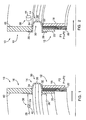
- FIG. 1 is a side elevation view of a high-pressure side of cartridge brush seal embodying the present invention.
- FIG. 2 is a side elevation view of a low-pressure side of the cartridge brush seal of FIG. 1.
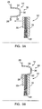
- FIG. 3A is a side elevation view showing a procedural step of assembling a brush seal to a mounting ring in accordance with the present invention.
- FIG. 3B is a side elevation view showing a procedural step of welding the brush seal to the mounting ring in accordance with the present invention.
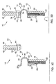
- FIG. 3C is a side elevation view showing a procedural step of assembling the brush seal and the mounting ring to a housing in accordance with the present invention.
- FIG. 3D is a side elevation view showing a procedural step of inserting an anti-rotation pin of the housing into a slot in the mounting ring in accordance with the present invention.
- FIG. 3E is a side elevation view showing the fully-assembled assembled brush seal.
- Referring to FIGS. 1-3, a cartridge-type brush seal assembly embodying the present invention is indicated generally by the
reference number 10. Theassembly 10 comprises anannular brush seal 12 and a resilientannular mounting ring 14 to be mounted to an annular housing or support such as, for example, ahousing 16. Thebrush seal 12 includes aback plate 18, aside plate 20 and a plurality ofbristles 22 disposed between the back plate and the side plate. Themounting ring 14, preferably made of metal, defines aslot 24 for the reason to be explained below. Themounting ring 14 includes a first mounting section orflange 26, a second mounting section orflange 28, and a substantially U-shaped or otherwisecurved ring section 30 extending between the mounting sections. Thering section 30 itself has afirst portion 32 extending from thefirst mounting section 26, and asecond portion 34 extending from thesecond mounting section 28. The first andsecond portions distal end 36 relative to themounting sections - As shown in FIG. 1, the annular housing or
support 16 includes a projection oranti-rotation pin 38 having afirst end 40 extending radially outwardly from a first or high-pressure side 42 (see FIG. 1) of theannular housing 16, and having asecond end 44 extending radially outwardly from a second or low-pressure side 46 (see FIG. 2) of the annular housing. As shown in FIG. 1, thefirst end 40 of theprojection 38 is received in theslot 24 defined by themounting ring 14 to prevent the mounting ring and thebrush seal 12 carried thereon from rotating relative to thehousing 16. Preferably, the size or diameter of thefirst end 40 of theprojection 38 is different from the size or diameter of thesecond end 44 in order to ensure that themounting ring 14 is coupled to thehousing 16 in the proper orientation. As shown in FIGS. 1 and 2, for example, thefirst end 40 of theprojection 38 has a smaller diameter relative to that of thesecond end 44 of the projection so that only the first end is sized to be received in theslot 24 of themounting ring 14. - The process for assembling the
brush seal assembly 10 in accordance with the present invention will now be explained with reference to FIGS. 3A through 3E. As shown in FIG. 3A, thebrush seal 12 is pressed into engagement with themounting ring 14 such that theside plate 20 abuts thefirst mounting section 26 of the mounting ring, and such that end portions of theside plate 20, the plurality ofbristles 22 and theback plate 18 abut thefirst portion 32 of thering section 30. Themounting ring 14 can be coupled to either an outer diameter of an inner diameter pointing brush seal, or to an inner diameter of an outer diameter pointing brush seal. As shown in FIG. 3B, theside plate 20 of thebrush seal 12 is coupled to thefirst mounting section 26 of themounting ring 14 by suitable coupling techniques such as, for example, soldering, brazing, welding and adhesive bonding. - With reference to FIG. 3C, the
mounting ring 14 carrying thebrush seal 12 is pushed into engagement with thehousing 16 such that thesecond mounting section 28 generally abuts the housing. Themounting ring 14 and thebrush seal 12 carried thereon are rotated relative to thehousing 16 until thefirst end 40 of theprojection 38 is aligned with theslot 24 of the mounting ring (see FIG. 3D). Themounting ring 14 is then further moved toward thehousing 16 such that thefirst end 40 of theprojection 38 of the housing is received through theslot 24 of the mounting ring 14 (see FIG. 3E). Theresilient mounting ring 14 acts as a spring and creates a light pressure on thehousing 16. This pressure, along with a positive pressure drop across thebrush seal 12 when in an operating environment holds theassembly 10 in place. - The present invention is well suited to be embodied as a small diameter (e.g., 6 inch (12.7 mm) outer diameter or less) low cost brush seal. Suitable applications of the present invention include, but are not limited to, small axial and centrifugal compressors, screw compressors, and small engines such as, for example, small aircraft engines.
- There are several benefits for employing a brush seal assembly in accordance with the present invention. The benefits include:
- 1) The brush seal assembly can be installed and removed without any special tools (preferably without any tools whatsoever);
- 2) The brush seal and support "fit diameters" can be machined to tolerances looser than those of current designs; the formed mounting ring, acting as a spring, can take up some of the deviations in size of the two pieces of hardware;
- 3) Reduced machining of support/housing structure, as there is no need to incorporate a diameter "step" to locate the downstream side of the seal;
- 4) Welding (or otherwise joining) the seal and mounting ring together eliminates the need for an anti-rotation device between the seal and mounting ring;
- 5) The anti-rotation device, a pin larger (i.e., head) on the downstream side than the upstream (part mounting) side, fool-proofs installation; and
- 6) Pressure loading holds the seal in place during operation (mounting ring must locate on upstream side of seal as shown in figures).
Claims (11)
- A brush seal assembly (10) comprising:a brush seal (12) including a back plate (18), a side plate (20) and a plurality of bristles (22) disposed between the back plate (18) and the side plate (20); anda resilient mounting ring (14) including at least one mounting section (26) for coupling to the brush seal (12), the mounting ring (14) defining a slot (24) for being received over a projection (40) of a housing (16) to prevent the mounting ring (14) and brush seal (12) to rotate relative to the housing.
- A brush seal assembly as defined in claim 1, wherein the brush seal (12) and the mounting ring (14) are annular in configuration.
- A brush seal assembly as defined in claim 1 or 2, wherein the mounting ring (14) includes:a first mounting section (26):a second mounting section (28); anda curved ring section (30) extending between the first and second mounting sections (26, 28).
- A brush seal assembly as defined in claim 3, wherein the first and second mounting sections (26, 28) each include a flange.
- A brush seal assembly as defined in claim 3 or 4, wherein the curved ring section (30) is substantially U-shaped.
- A brush seal assembly as defined in claim 3, 4 or 5, wherein the side plate (20) abuts one of the mounting sections (26) and abuts the curved ring section (30).
- A method of assembling a brush seal assembly (10), comprising the steps of:providing an annular brush seal (12) including a back plate (18), a side plate (20) and a plurality of bristles (22) disposed between the back plate (18) and the side plate (20);providing a resilient annular mounting ring (14) including a first mounting section (26), a second mounting section (28) defining a slot (24), and a curved section (30) extending between the mounting sections (26, 28);providing an annular housing (16) including a mounting projection (40);engaging the side plate (20) of the annular brush seal (12) with the first mounting section (26) and the curved section (30) of the mounting ring (14);coupling the brush seal (12) to the mounting ring (14); andengaging the housing (16) with the second mounting section (28) and the curved section (30) of the mounting ring (14) such that the mounting projection (40) of the housing (16) is received in the slot (24) defined by the second mounting section (28) of the mounting ring (14).
- A method of assembling as defined in claim 7, wherein the step of coupling the brush seal (12) to the mounting ring (14) includes soldering the brush seal (12) to the mounting ring (14).
- A method of assembling as defined in claim 7, wherein the step of coupling the brush seal (12) to the mounting ring (14) includes brazing the brush seal (12) to the mounting ring (14).
- A method of assembling as defined in claim 7, wherein the step of coupling the brush seal (12) to the mounting ring (14) includes welding the brush seal (12) to the mounting ring (14).
- A method of assembling as defined in claim 7, wherein the step of coupling the brush seal (12) to the mounting ring (14) includes adhesively bonding the brush seal (12) to the mounting ring (14).
Applications Claiming Priority (1)
| Application Number | Priority Date | Filing Date | Title |
|---|---|---|---|
| US11/137,066 US20060267291A1 (en) | 2005-05-25 | 2005-05-25 | Brush seal assembly and method of assembling same |
Publications (2)
| Publication Number | Publication Date |
|---|---|
| EP1726853A1 true EP1726853A1 (en) | 2006-11-29 |
| EP1726853B1 EP1726853B1 (en) | 2008-11-26 |
Family
ID=36997742
Family Applications (1)
| Application Number | Title | Priority Date | Filing Date |
|---|---|---|---|
| EP06252652A Not-in-force EP1726853B1 (en) | 2005-05-25 | 2006-05-22 | Brush seal assembly and method for assembling same |
Country Status (4)
| Country | Link |
|---|---|
| US (1) | US20060267291A1 (en) |
| EP (1) | EP1726853B1 (en) |
| JP (1) | JP2006329424A (en) |
| DE (1) | DE602006003809D1 (en) |
Families Citing this family (3)
| Publication number | Priority date | Publication date | Assignee | Title |
|---|---|---|---|---|
| US7967297B2 (en) * | 2007-03-13 | 2011-06-28 | Eaton Corporation | Thermally-activated control gap brush seal |
| EP3270014B1 (en) * | 2015-03-09 | 2020-11-11 | Eagle Industry Co., Ltd. | Divided-type brush seal device |
| US10968763B2 (en) * | 2019-02-01 | 2021-04-06 | Raytheon Technologies Corporation | HALO seal build clearance methods |
Citations (5)
| Publication number | Priority date | Publication date | Assignee | Title |
|---|---|---|---|---|
| GB2119037A (en) * | 1982-04-22 | 1983-11-09 | Steinmueller Gmbh L & C | A sealing system for a regenerative heat exchanger |
| US5474305A (en) * | 1990-09-18 | 1995-12-12 | Cross Manufacturing Company (1938) Limited | Sealing device |
| US5503405A (en) * | 1991-05-07 | 1996-04-02 | General Electric Co. | Apparatus for providing uniform radial clearance of seals between rotating and stationary components |
| US20040007822A1 (en) * | 2002-07-11 | 2004-01-15 | Mortzheim Jason Paul | Brush seal placement between rotating and stationary components with reversely bent leaf spring |
| US20050098958A1 (en) * | 2003-11-07 | 2005-05-12 | The Boeing Company | Gas-buffered seal assembly and method therefor |
Family Cites Families (17)
| Publication number | Priority date | Publication date | Assignee | Title |
|---|---|---|---|---|
| US1817238A (en) * | 1929-03-11 | 1931-08-04 | William F Cremean | Dustguard |
| US1838661A (en) * | 1930-01-21 | 1931-12-29 | William F Cremean | Dust guard |
| US3019035A (en) * | 1957-12-17 | 1962-01-30 | Orenda Engines Ltd | Mounting mechanism for labyrinth seal disc |
| US4115203A (en) * | 1977-01-06 | 1978-09-19 | Wilputte Corporation | Seal for coke oven doors |
| JPH0448361Y2 (en) * | 1987-05-08 | 1992-11-13 | ||
| US5425543A (en) * | 1993-09-17 | 1995-06-20 | Buckshaw; Dennis J. | Seal assembly for rotating shaft |
| US5597167A (en) * | 1994-09-28 | 1997-01-28 | United Technologies Corporation | Brush seal with fool proofing and anti-rotation tab |
| US5498139A (en) * | 1994-11-09 | 1996-03-12 | United Technologies Corporation | Brush seal |
| US5639211A (en) * | 1995-11-30 | 1997-06-17 | United Technology Corporation | Brush seal for stator of a gas turbine engine case |
| US5630590A (en) * | 1996-03-26 | 1997-05-20 | United Technologies Corporation | Method and apparatus for improving the airsealing effectiveness in a turbine engine |
| US6170831B1 (en) * | 1998-12-23 | 2001-01-09 | United Technologies Corporation | Axial brush seal for gas turbine engines |
| JP2001050396A (en) * | 1999-08-05 | 2001-02-23 | Toshiba Corp | Brush seal device |
| US6457719B1 (en) * | 2000-08-14 | 2002-10-01 | United Technologies Corporation | Brush seal |
| US6547257B2 (en) * | 2001-05-04 | 2003-04-15 | General Electric Company | Combination transition piece floating cloth seal and stage 1 turbine nozzle flexible sealing element |
| US8181965B2 (en) * | 2002-06-27 | 2012-05-22 | United Technologies Corporation | Replaceable brush seal elements |
| US7093835B2 (en) * | 2002-08-27 | 2006-08-22 | United Technologies Corporation | Floating brush seal assembly |
| DE10320450B4 (en) * | 2003-05-08 | 2013-07-18 | Mtu Aero Engines Gmbh | sealing arrangement |
-
2005
- 2005-05-25 US US11/137,066 patent/US20060267291A1/en not_active Abandoned
-
2006
- 2006-05-22 EP EP06252652A patent/EP1726853B1/en not_active Not-in-force
- 2006-05-22 DE DE602006003809T patent/DE602006003809D1/en active Active
- 2006-05-25 JP JP2006144749A patent/JP2006329424A/en active Pending
Patent Citations (5)
| Publication number | Priority date | Publication date | Assignee | Title |
|---|---|---|---|---|
| GB2119037A (en) * | 1982-04-22 | 1983-11-09 | Steinmueller Gmbh L & C | A sealing system for a regenerative heat exchanger |
| US5474305A (en) * | 1990-09-18 | 1995-12-12 | Cross Manufacturing Company (1938) Limited | Sealing device |
| US5503405A (en) * | 1991-05-07 | 1996-04-02 | General Electric Co. | Apparatus for providing uniform radial clearance of seals between rotating and stationary components |
| US20040007822A1 (en) * | 2002-07-11 | 2004-01-15 | Mortzheim Jason Paul | Brush seal placement between rotating and stationary components with reversely bent leaf spring |
| US20050098958A1 (en) * | 2003-11-07 | 2005-05-12 | The Boeing Company | Gas-buffered seal assembly and method therefor |
Also Published As
| Publication number | Publication date |
|---|---|
| DE602006003809D1 (en) | 2009-01-08 |
| US20060267291A1 (en) | 2006-11-30 |
| EP1726853B1 (en) | 2008-11-26 |
| JP2006329424A (en) | 2006-12-07 |
Similar Documents
| Publication | Publication Date | Title |
|---|---|---|
| US10576613B2 (en) | Methods and tools for pressing a ring seal into a component | |
| CN104583650B (en) | Brush seal | |
| EP2105582A2 (en) | Gas turbine engine seals and engines incorporating such seals | |
| CN1760510B (en) | Gas turbine engine and variable vane assembly for a gas turbine engine | |
| US6681486B2 (en) | Method of forming brush seals between rotating components | |
| US9689497B2 (en) | Brush seal device | |
| AU2020400781A1 (en) | Composite seal structure for a machine, and method of manufacturing the composite seal structure | |
| EP1726853B1 (en) | Brush seal assembly and method for assembling same | |
| US10502322B2 (en) | Split type brush seal device, brush seal pieces, and method of assembling split type brush seal device | |
| EP3550183B1 (en) | Multi-plane brush seal | |
| US6874787B2 (en) | Brush seal device | |
| US5328101A (en) | Gas turbine fuel nozzle seal | |
| US7909334B2 (en) | Sealing arrangement and method for the production thereof | |
| CN114667422B (en) | Power element and expansion valve using the same | |
| EP4438927A1 (en) | Non-contact seal with seal device axial locator(s) | |
| EP3591177B1 (en) | Nut strip assembly with array of captured nuts | |
| US7387301B2 (en) | Brush seal for sealing a gap between a rotor and a stator | |
| EP3550184A1 (en) | Multi-plane brush seal | |
| WO2003091609A1 (en) | Brush seals | |
| JPH10299407A (en) | Gas turbine engine rotor | |
| EP3599379B1 (en) | High efficiency gear pump bearing assembly | |
| JP6864273B2 (en) | Turbofan engine center vent tube support | |
| US20250347368A1 (en) | Non rotating spacer for gas turbine engine | |
| EP3795803B1 (en) | Self-centering seal and method of using same | |
| JP2009008002A (en) | Liner ring |
Legal Events
| Date | Code | Title | Description |
|---|---|---|---|
| PUAI | Public reference made under article 153(3) epc to a published international application that has entered the european phase |
Free format text: ORIGINAL CODE: 0009012 |
|
| AK | Designated contracting states |
Kind code of ref document: A1 Designated state(s): AT BE BG CH CY CZ DE DK EE ES FI FR GB GR HU IE IS IT LI LT LU LV MC NL PL PT RO SE SI SK TR |
|
| AX | Request for extension of the european patent |
Extension state: AL BA HR MK YU |
|
| 17P | Request for examination filed |
Effective date: 20070529 |
|
| 17Q | First examination report despatched |
Effective date: 20070703 |
|
| AKX | Designation fees paid |
Designated state(s): DE FR GB |
|
| GRAP | Despatch of communication of intention to grant a patent |
Free format text: ORIGINAL CODE: EPIDOSNIGR1 |
|
| GRAS | Grant fee paid |
Free format text: ORIGINAL CODE: EPIDOSNIGR3 |
|
| GRAA | (expected) grant |
Free format text: ORIGINAL CODE: 0009210 |
|
| AK | Designated contracting states |
Kind code of ref document: B1 Designated state(s): DE FR GB |
|
| REG | Reference to a national code |
Ref country code: GB Ref legal event code: FG4D |
|
| REF | Corresponds to: |
Ref document number: 602006003809 Country of ref document: DE Date of ref document: 20090108 Kind code of ref document: P |
|
| PLBE | No opposition filed within time limit |
Free format text: ORIGINAL CODE: 0009261 |
|
| STAA | Information on the status of an ep patent application or granted ep patent |
Free format text: STATUS: NO OPPOSITION FILED WITHIN TIME LIMIT |
|
| 26N | No opposition filed |
Effective date: 20090827 |
|
| REG | Reference to a national code |
Ref country code: FR Ref legal event code: ST Effective date: 20100129 |
|
| PG25 | Lapsed in a contracting state [announced via postgrant information from national office to epo] |
Ref country code: FR Free format text: LAPSE BECAUSE OF NON-PAYMENT OF DUE FEES Effective date: 20090602 |
|
| REG | Reference to a national code |
Ref country code: DE Ref legal event code: R082 Ref document number: 602006003809 Country of ref document: DE Representative=s name: SCHMITT-NILSON SCHRAUD WAIBEL WOHLFROM PATENTA, DE |
|
| REG | Reference to a national code |
Ref country code: DE Ref legal event code: R082 Ref document number: 602006003809 Country of ref document: DE Representative=s name: SCHMITT-NILSON SCHRAUD WAIBEL WOHLFROM PATENTA, DE Ref country code: DE Ref legal event code: R081 Ref document number: 602006003809 Country of ref document: DE Owner name: UNITED TECHNOLOGIES CORP. (N.D.GES.D. STAATES , US Free format text: FORMER OWNER: UNITED TECHNOLOGIES CORPORATION, HARTFORD, CONN., US |
|
| PGFP | Annual fee paid to national office [announced via postgrant information from national office to epo] |
Ref country code: DE Payment date: 20190418 Year of fee payment: 14 |
|
| REG | Reference to a national code |
Ref country code: DE Ref legal event code: R119 Ref document number: 602006003809 Country of ref document: DE |
|
| PG25 | Lapsed in a contracting state [announced via postgrant information from national office to epo] |
Ref country code: DE Free format text: LAPSE BECAUSE OF NON-PAYMENT OF DUE FEES Effective date: 20201201 |
|
| PGFP | Annual fee paid to national office [announced via postgrant information from national office to epo] |
Ref country code: GB Payment date: 20230420 Year of fee payment: 18 |
|
| GBPC | Gb: european patent ceased through non-payment of renewal fee |
Effective date: 20240522 |
|
| PG25 | Lapsed in a contracting state [announced via postgrant information from national office to epo] |
Ref country code: GB Free format text: LAPSE BECAUSE OF NON-PAYMENT OF DUE FEES Effective date: 20240522 |