EP1726795A2 - Honeycomb structural body and exhaust gas purifying apparatus - Google Patents
Honeycomb structural body and exhaust gas purifying apparatus Download PDFInfo
- Publication number
- EP1726795A2 EP1726795A2 EP05710173A EP05710173A EP1726795A2 EP 1726795 A2 EP1726795 A2 EP 1726795A2 EP 05710173 A EP05710173 A EP 05710173A EP 05710173 A EP05710173 A EP 05710173A EP 1726795 A2 EP1726795 A2 EP 1726795A2
- Authority
- EP
- European Patent Office
- Prior art keywords
- structural body
- honeycomb structural
- holes
- capacity
- cross
- Prior art date
- Legal status (The legal status is an assumption and is not a legal conclusion. Google has not performed a legal analysis and makes no representation as to the accuracy of the status listed.)
- Ceased
Links
Images





Classifications
-
- F—MECHANICAL ENGINEERING; LIGHTING; HEATING; WEAPONS; BLASTING
- F01—MACHINES OR ENGINES IN GENERAL; ENGINE PLANTS IN GENERAL; STEAM ENGINES
- F01N—GAS-FLOW SILENCERS OR EXHAUST APPARATUS FOR MACHINES OR ENGINES IN GENERAL; GAS-FLOW SILENCERS OR EXHAUST APPARATUS FOR INTERNAL-COMBUSTION ENGINES
- F01N3/00—Exhaust or silencing apparatus having means for purifying, rendering innocuous, or otherwise treating exhaust
- F01N3/02—Exhaust or silencing apparatus having means for purifying, rendering innocuous, or otherwise treating exhaust for cooling, or for removing solid constituents of, exhaust
- F01N3/021—Exhaust or silencing apparatus having means for purifying, rendering innocuous, or otherwise treating exhaust for cooling, or for removing solid constituents of, exhaust by means of filters
- F01N3/022—Exhaust or silencing apparatus having means for purifying, rendering innocuous, or otherwise treating exhaust for cooling, or for removing solid constituents of, exhaust by means of filters characterised by specially adapted filtering structure, e.g. honeycomb, mesh or fibrous
- F01N3/0222—Exhaust or silencing apparatus having means for purifying, rendering innocuous, or otherwise treating exhaust for cooling, or for removing solid constituents of, exhaust by means of filters characterised by specially adapted filtering structure, e.g. honeycomb, mesh or fibrous the structure being monolithic, e.g. honeycombs
-
- B—PERFORMING OPERATIONS; TRANSPORTING
- B01—PHYSICAL OR CHEMICAL PROCESSES OR APPARATUS IN GENERAL
- B01D—SEPARATION
- B01D39/00—Filtering material for liquid or gaseous fluids
- B01D39/14—Other self-supporting filtering material ; Other filtering material
- B01D39/20—Other self-supporting filtering material ; Other filtering material of inorganic material, e.g. asbestos paper, metallic filtering material of non-woven wires
-
- B—PERFORMING OPERATIONS; TRANSPORTING
- B01—PHYSICAL OR CHEMICAL PROCESSES OR APPARATUS IN GENERAL
- B01D—SEPARATION
- B01D46/00—Filters or filtering processes specially modified for separating dispersed particles from gases or vapours
- B01D46/24—Particle separators, e.g. dust precipitators, using rigid hollow filter bodies
- B01D46/2403—Particle separators, e.g. dust precipitators, using rigid hollow filter bodies characterised by the physical shape or structure of the filtering element
- B01D46/2418—Honeycomb filters
- B01D46/2425—Honeycomb filters characterized by parameters related to the physical properties of the honeycomb structure material
-
- B—PERFORMING OPERATIONS; TRANSPORTING
- B01—PHYSICAL OR CHEMICAL PROCESSES OR APPARATUS IN GENERAL
- B01D—SEPARATION
- B01D46/00—Filters or filtering processes specially modified for separating dispersed particles from gases or vapours
- B01D46/24—Particle separators, e.g. dust precipitators, using rigid hollow filter bodies
- B01D46/2403—Particle separators, e.g. dust precipitators, using rigid hollow filter bodies characterised by the physical shape or structure of the filtering element
- B01D46/2418—Honeycomb filters
- B01D46/2425—Honeycomb filters characterized by parameters related to the physical properties of the honeycomb structure material
- B01D46/2429—Honeycomb filters characterized by parameters related to the physical properties of the honeycomb structure material of the honeycomb walls or cells
-
- B—PERFORMING OPERATIONS; TRANSPORTING
- B01—PHYSICAL OR CHEMICAL PROCESSES OR APPARATUS IN GENERAL
- B01D—SEPARATION
- B01D46/00—Filters or filtering processes specially modified for separating dispersed particles from gases or vapours
- B01D46/24—Particle separators, e.g. dust precipitators, using rigid hollow filter bodies
- B01D46/2403—Particle separators, e.g. dust precipitators, using rigid hollow filter bodies characterised by the physical shape or structure of the filtering element
- B01D46/2418—Honeycomb filters
- B01D46/2425—Honeycomb filters characterized by parameters related to the physical properties of the honeycomb structure material
- B01D46/24491—Porosity
-
- B—PERFORMING OPERATIONS; TRANSPORTING
- B01—PHYSICAL OR CHEMICAL PROCESSES OR APPARATUS IN GENERAL
- B01D—SEPARATION
- B01D46/00—Filters or filtering processes specially modified for separating dispersed particles from gases or vapours
- B01D46/24—Particle separators, e.g. dust precipitators, using rigid hollow filter bodies
- B01D46/2403—Particle separators, e.g. dust precipitators, using rigid hollow filter bodies characterised by the physical shape or structure of the filtering element
- B01D46/2418—Honeycomb filters
- B01D46/2425—Honeycomb filters characterized by parameters related to the physical properties of the honeycomb structure material
- B01D46/24492—Pore diameter
-
- B—PERFORMING OPERATIONS; TRANSPORTING
- B01—PHYSICAL OR CHEMICAL PROCESSES OR APPARATUS IN GENERAL
- B01D—SEPARATION
- B01D46/00—Filters or filtering processes specially modified for separating dispersed particles from gases or vapours
- B01D46/24—Particle separators, e.g. dust precipitators, using rigid hollow filter bodies
- B01D46/2403—Particle separators, e.g. dust precipitators, using rigid hollow filter bodies characterised by the physical shape or structure of the filtering element
- B01D46/2418—Honeycomb filters
- B01D46/2451—Honeycomb filters characterized by the geometrical structure, shape, pattern or configuration or parameters related to the geometry of the structure
-
- B—PERFORMING OPERATIONS; TRANSPORTING
- B01—PHYSICAL OR CHEMICAL PROCESSES OR APPARATUS IN GENERAL
- B01D—SEPARATION
- B01D46/00—Filters or filtering processes specially modified for separating dispersed particles from gases or vapours
- B01D46/24—Particle separators, e.g. dust precipitators, using rigid hollow filter bodies
- B01D46/2403—Particle separators, e.g. dust precipitators, using rigid hollow filter bodies characterised by the physical shape or structure of the filtering element
- B01D46/2418—Honeycomb filters
- B01D46/2451—Honeycomb filters characterized by the geometrical structure, shape, pattern or configuration or parameters related to the geometry of the structure
- B01D46/2455—Honeycomb filters characterized by the geometrical structure, shape, pattern or configuration or parameters related to the geometry of the structure of the whole honeycomb or segments
-
- B—PERFORMING OPERATIONS; TRANSPORTING
- B01—PHYSICAL OR CHEMICAL PROCESSES OR APPARATUS IN GENERAL
- B01D—SEPARATION
- B01D46/00—Filters or filtering processes specially modified for separating dispersed particles from gases or vapours
- B01D46/24—Particle separators, e.g. dust precipitators, using rigid hollow filter bodies
- B01D46/2403—Particle separators, e.g. dust precipitators, using rigid hollow filter bodies characterised by the physical shape or structure of the filtering element
- B01D46/2418—Honeycomb filters
- B01D46/2451—Honeycomb filters characterized by the geometrical structure, shape, pattern or configuration or parameters related to the geometry of the structure
- B01D46/247—Honeycomb filters characterized by the geometrical structure, shape, pattern or configuration or parameters related to the geometry of the structure of the cells
-
- B—PERFORMING OPERATIONS; TRANSPORTING
- B01—PHYSICAL OR CHEMICAL PROCESSES OR APPARATUS IN GENERAL
- B01D—SEPARATION
- B01D46/00—Filters or filtering processes specially modified for separating dispersed particles from gases or vapours
- B01D46/24—Particle separators, e.g. dust precipitators, using rigid hollow filter bodies
- B01D46/2403—Particle separators, e.g. dust precipitators, using rigid hollow filter bodies characterised by the physical shape or structure of the filtering element
- B01D46/2418—Honeycomb filters
- B01D46/2451—Honeycomb filters characterized by the geometrical structure, shape, pattern or configuration or parameters related to the geometry of the structure
- B01D46/2478—Structures comprising honeycomb segments
-
- B—PERFORMING OPERATIONS; TRANSPORTING
- B01—PHYSICAL OR CHEMICAL PROCESSES OR APPARATUS IN GENERAL
- B01D—SEPARATION
- B01D46/00—Filters or filtering processes specially modified for separating dispersed particles from gases or vapours
- B01D46/24—Particle separators, e.g. dust precipitators, using rigid hollow filter bodies
- B01D46/2403—Particle separators, e.g. dust precipitators, using rigid hollow filter bodies characterised by the physical shape or structure of the filtering element
- B01D46/2418—Honeycomb filters
- B01D46/2451—Honeycomb filters characterized by the geometrical structure, shape, pattern or configuration or parameters related to the geometry of the structure
- B01D46/2484—Cell density, area or aspect ratio
-
- B—PERFORMING OPERATIONS; TRANSPORTING
- B01—PHYSICAL OR CHEMICAL PROCESSES OR APPARATUS IN GENERAL
- B01D—SEPARATION
- B01D46/00—Filters or filtering processes specially modified for separating dispersed particles from gases or vapours
- B01D46/24—Particle separators, e.g. dust precipitators, using rigid hollow filter bodies
- B01D46/2403—Particle separators, e.g. dust precipitators, using rigid hollow filter bodies characterised by the physical shape or structure of the filtering element
- B01D46/2418—Honeycomb filters
- B01D46/2451—Honeycomb filters characterized by the geometrical structure, shape, pattern or configuration or parameters related to the geometry of the structure
- B01D46/2486—Honeycomb filters characterized by the geometrical structure, shape, pattern or configuration or parameters related to the geometry of the structure characterised by the shapes or configurations
-
- B—PERFORMING OPERATIONS; TRANSPORTING
- B01—PHYSICAL OR CHEMICAL PROCESSES OR APPARATUS IN GENERAL
- B01D—SEPARATION
- B01D46/00—Filters or filtering processes specially modified for separating dispersed particles from gases or vapours
- B01D46/24—Particle separators, e.g. dust precipitators, using rigid hollow filter bodies
- B01D46/2403—Particle separators, e.g. dust precipitators, using rigid hollow filter bodies characterised by the physical shape or structure of the filtering element
- B01D46/2418—Honeycomb filters
- B01D46/2451—Honeycomb filters characterized by the geometrical structure, shape, pattern or configuration or parameters related to the geometry of the structure
- B01D46/2486—Honeycomb filters characterized by the geometrical structure, shape, pattern or configuration or parameters related to the geometry of the structure characterised by the shapes or configurations
- B01D46/249—Quadrangular e.g. square or diamond
-
- B—PERFORMING OPERATIONS; TRANSPORTING
- B01—PHYSICAL OR CHEMICAL PROCESSES OR APPARATUS IN GENERAL
- B01D—SEPARATION
- B01D46/00—Filters or filtering processes specially modified for separating dispersed particles from gases or vapours
- B01D46/24—Particle separators, e.g. dust precipitators, using rigid hollow filter bodies
- B01D46/2403—Particle separators, e.g. dust precipitators, using rigid hollow filter bodies characterised by the physical shape or structure of the filtering element
- B01D46/2418—Honeycomb filters
- B01D46/2451—Honeycomb filters characterized by the geometrical structure, shape, pattern or configuration or parameters related to the geometry of the structure
- B01D46/2486—Honeycomb filters characterized by the geometrical structure, shape, pattern or configuration or parameters related to the geometry of the structure characterised by the shapes or configurations
- B01D46/2494—Octagonal
-
- B—PERFORMING OPERATIONS; TRANSPORTING
- B01—PHYSICAL OR CHEMICAL PROCESSES OR APPARATUS IN GENERAL
- B01D—SEPARATION
- B01D46/00—Filters or filtering processes specially modified for separating dispersed particles from gases or vapours
- B01D46/24—Particle separators, e.g. dust precipitators, using rigid hollow filter bodies
- B01D46/2403—Particle separators, e.g. dust precipitators, using rigid hollow filter bodies characterised by the physical shape or structure of the filtering element
- B01D46/2418—Honeycomb filters
- B01D46/2498—The honeycomb filter being defined by mathematical relationships
-
- B—PERFORMING OPERATIONS; TRANSPORTING
- B01—PHYSICAL OR CHEMICAL PROCESSES OR APPARATUS IN GENERAL
- B01J—CHEMICAL OR PHYSICAL PROCESSES, e.g. CATALYSIS OR COLLOID CHEMISTRY; THEIR RELEVANT APPARATUS
- B01J35/00—Catalysts, in general, characterised by their form or physical properties
- B01J35/50—Catalysts, in general, characterised by their form or physical properties characterised by their shape or configuration
- B01J35/56—Foraminous structures having flow-through passages or channels, e.g. grids or three-dimensional [3D] monoliths
- B01J35/57—Honeycombs
-
- B—PERFORMING OPERATIONS; TRANSPORTING
- B01—PHYSICAL OR CHEMICAL PROCESSES OR APPARATUS IN GENERAL
- B01D—SEPARATION
- B01D2279/00—Filters adapted for separating dispersed particles from gases or vapours specially modified for specific uses
- B01D2279/30—Filters adapted for separating dispersed particles from gases or vapours specially modified for specific uses for treatment of exhaust gases from IC Engines
-
- F—MECHANICAL ENGINEERING; LIGHTING; HEATING; WEAPONS; BLASTING
- F01—MACHINES OR ENGINES IN GENERAL; ENGINE PLANTS IN GENERAL; STEAM ENGINES
- F01N—GAS-FLOW SILENCERS OR EXHAUST APPARATUS FOR MACHINES OR ENGINES IN GENERAL; GAS-FLOW SILENCERS OR EXHAUST APPARATUS FOR INTERNAL-COMBUSTION ENGINES
- F01N2330/00—Structure of catalyst support or particle filter
- F01N2330/30—Honeycomb supports characterised by their structural details
- F01N2330/48—Honeycomb supports characterised by their structural details characterised by the number of flow passages, e.g. cell density
-
- F—MECHANICAL ENGINEERING; LIGHTING; HEATING; WEAPONS; BLASTING
- F01—MACHINES OR ENGINES IN GENERAL; ENGINE PLANTS IN GENERAL; STEAM ENGINES
- F01N—GAS-FLOW SILENCERS OR EXHAUST APPARATUS FOR MACHINES OR ENGINES IN GENERAL; GAS-FLOW SILENCERS OR EXHAUST APPARATUS FOR INTERNAL-COMBUSTION ENGINES
- F01N2340/00—Dimensional characteristics of the exhaust system, e.g. length, diameter or volume of the exhaust apparatus; Spatial arrangements of exhaust apparatuses
-
- Y—GENERAL TAGGING OF NEW TECHNOLOGICAL DEVELOPMENTS; GENERAL TAGGING OF CROSS-SECTIONAL TECHNOLOGIES SPANNING OVER SEVERAL SECTIONS OF THE IPC; TECHNICAL SUBJECTS COVERED BY FORMER USPC CROSS-REFERENCE ART COLLECTIONS [XRACs] AND DIGESTS
- Y02—TECHNOLOGIES OR APPLICATIONS FOR MITIGATION OR ADAPTATION AGAINST CLIMATE CHANGE
- Y02T—CLIMATE CHANGE MITIGATION TECHNOLOGIES RELATED TO TRANSPORTATION
- Y02T10/00—Road transport of goods or passengers
- Y02T10/10—Internal combustion engine [ICE] based vehicles
- Y02T10/12—Improving ICE efficiencies
-
- Y—GENERAL TAGGING OF NEW TECHNOLOGICAL DEVELOPMENTS; GENERAL TAGGING OF CROSS-SECTIONAL TECHNOLOGIES SPANNING OVER SEVERAL SECTIONS OF THE IPC; TECHNICAL SUBJECTS COVERED BY FORMER USPC CROSS-REFERENCE ART COLLECTIONS [XRACs] AND DIGESTS
- Y10—TECHNICAL SUBJECTS COVERED BY FORMER USPC
- Y10T—TECHNICAL SUBJECTS COVERED BY FORMER US CLASSIFICATION
- Y10T428/00—Stock material or miscellaneous articles
- Y10T428/24—Structurally defined web or sheet [e.g., overall dimension, etc.]
- Y10T428/24149—Honeycomb-like
Definitions
- the present invention relates to a honeycomb structural body and an exhaust gas purifying device used for the purpose of removing particulates and the like in exhaust gases discharged from an internal combustion engine such as a diesel engine.
- particulates contained in exhaust gases discharged from internal combustion engines of vehicles such as buses, trucks, construction machines and the like, have raised serious problems as these particulates are harmful to the environment and the human body.
- various honeycomb structural bodies used as ceramics filters which allow exhaust gases to pass through porous ceramics to collect particulates in the exhaust gases, so that the exhaust gases can be purified.
- through hole on flow-in side a ceramic filter wherein through holes an end of each of them on a side from which exhaust gases flow out is sealed
- through hole on flow-in side a ceramic filter wherein through holes an end of each of them on a side from which exhaust gases flow out is sealed
- large-capacity through hole a large volume
- through hole on flow-out side through holes an end of each of them on a side to which exhaust gases flow in is sealed
- small-capacity through hole small volume
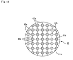
- Fig. 18 is a cross-sectional view showing schematically a cross-section perpendicular to the length direction of a conventional exhaust gas filter.
- This exhaust-gas filter 60 has a cross-sectional structure in which squares, each smaller than each of square shapes constituting the checker board pattern, are placed on intersections of the checker board pattern, and this structure is constituted by small-capacity through holes 61b corresponding to the smaller squares and large-capacity through holes 61a located on the periphery thereof, with the partition wall 62a, 62b being formed between these through holes (see Patent Documents 1 and 2).
- Figs. 19(a) to 19(d) are cross-sectional views each showing schematically a cross-section perpendicular to the length direction of another conventional exhaust filter.
- These exhaust gas filters 300 to 330 are composed of large-capacity through holes 301a, 311a, 321a, and 331a having various shapes, respectively, and small-capacity through holes 301b, 311b, 321b, and 331b having various shapes, respectively.
- Portions of the partition wall 302, 312, 322, and 332 are formed between these through holes, respectively.
- any of the portions of the partition wall 302, 312, 322, and 332 is the one for separating each of the large-capacity through holes 301a, 311a, 321a, and 331a and each of the small-capacity through holes 301b, 311b, 321b, 331b, respectively.
- no partition wall for separating the large-capacity through holes 301a, 311a, 321a, and 331a from one another exists (see Patent Documents 3 to 7).
- a filter wherein a cell pitch of large-capacity through holes is made to be almost 1.0 to 2.5 mm is disclosed as another prior art (see Patent Document 8).
- a filter wherein a volume ratio in large-capacity through holes is 60 to 70%, a volume ratio in small-capacity through holes is 20 to 30%, and a cell pitch of the large-capacity through holes is almost 2.5 to 5.0 mm is also disclosed (see Patent Document 9).
- Fig. 20 is a cross-sectional view showing schematically a cross-section perpendicular to the length direction (hereinafter optionally referred simply to as "cross-section") of each of the above-mentioned filters 200.
- cross-section perpendicular to the length direction (hereinafter optionally referred simply to as "cross-section") of each of the above-mentioned filters 200.
- small-capacity through holes 202 each having a triangular cross-section are disposed around each large-capacity through hole 201 having a hexagonal cross-section.
- a filter having 40 to 120% of a percentage of a ratio of a gross area in cross-sections of small-capacity through holes with respect to a gross area in cross-sections of large-capacity through holes is also disclosed (see Patent Documents 10 and 11).
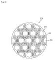
- Fig. 21 is a cross-sectional view that schematically shows a cross-section perpendicular to the length direction of such a honeycomb structural body, and in a filter 210, small-capacity through holes 212, each having an laterally elongated hexagonal shape in its cross section, are placed on the periphery of a large-capacity through hole 211 having a right hexagonal shape in its cross section.
- the large-capacity through holes 211 having a right hexagonal shape and large-capacity through holes 213 having a trapezoidal shape are placed also in parallel with each other.
- a filter wherein the number of through holes on its flow-in side is made larger than that of its flow-out side, whereby an aperture ratio on the flow-in side of exhaust gases is made to be relatively larger than that of the flow-out side of the exhaust gases is also disclosed (For example, see Fig. 3 of Patent Document 10).
- Patent Documents 12 and 13 a technique for adjusting a thickness of a wall, and physical properties of a filter are also disclosed (see Patent Documents 12 and 13).
- a filter containing through holes having square and rectangular cross-sections is also disclosed (see Patent Document 14).
- a filter containing through holes having two types of shapes is also disclosed (see Patent Documents 15 and 16).
- Another filter containing through holes having two types of shapes, i.e. relatively large square and small square shapes is disclosed (see Patent Document 17).
- Patent Document 1 US Patent No. 4417908 Patent Document 2: JP-A 58-196820 (1983 ) Patent Document 3: US Patent No. 4364761 Patent Document 4: JP-A 56-124417 (1981 ) Patent Document 5: JP-A 62-96717 (1987 ) Patent Document 6: US Patent No. 4276071 Patent Document 7: JP-A 56-124418 (1981 ) Patent Document 8: J UM-A56-187890 microfilm (1981) (J UM-A 58-92409 (see page 4, Fig.6) Patent Document 9: JP-A 5-68828 (1993 ) ( Japanese Patent No. 3130587 (page 1)) Patent Document 10: JP-A 2001-334114 (see page 5, Fig.
- Patent Document 11 International Publication No. WO02/100514
- Patent Document 12 US Patent No. 4416676
- Patent Document 13 US Patent No. 4420316
- Patent Document 14 JP-A 58-150015 (1983 )
- Patent Document 15 French Patent No. 2789327
- Patent Document 16 International Publication No. WO02/10562
- Patent Document 17 International Publication No. WO03/20407
- Patent Document 18 International Publication No. WO03/80218
- a volume of a filter when a volume of a filter is allowed to increase without changing an aperture ratio on an inlet side, whereby a specific surface anda total volume of a throughhole (filtration area) are also allowed to increase, a pressure loss can be reduced.
- a volume of a filter when a volume of a filter is increased, it becomes difficult to maintain a space for locating the filter in the periphery of an internal combustion engine, further, thermal responsiveness decreases with increase in the volume, or it becomes difficult to burn off soot, and cracks appear easily due to thermal shock. Accordingly, it is not an effective countermeasure to simply increase a volume in a filter for solving the above-mentioned problems.
- the present inventor studies eagerly to solve the above-mentioned problems. As a result, it has been found that a life of a honeycomb structural body can be prolonged while keeping a size of the honeycomb structural body in a compact state so far as a predetermined relation is satisfied between a volume of the honeycomb structural body and an aperture ratio on an inlet side of the honeycomb structural body, and that the resulting honeycomb structural body exhibits high critical value for the appearance of cracks because it is excellent in thermal responsiveness, so that a reliably excellent honeycomb structural body is obtained. Thus, the present invention was completed.
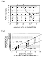
- a honeycomb structural body is a pillar-shaped honeycomb structural body having a honeycomb structure that a number of through holes are placed in parallel with one another in the length direction with a wall portion interposed therebetween and one of ends of each through hole is sealed, wherein a relation between a volume Y (L) of the honeycomb structural body and an aperture ratio X (%) on an inlet side satisfies the following inequality (1): Y ⁇ - 1.1 X + 68.5 ( wherein Y ⁇ 19 , 35 ⁇ X ⁇ 56 )
- the relation between the volume Y (L) of the honeycomb structural body and the aperture ratio X (%) on the inlet side satisfies the following inequality (2): Y ⁇ - 1.1 X + 66.3 (wherein 2.5 ⁇ Y ⁇ 19 , 35 ⁇ X ⁇ 56 )
- a relation among the volume Y (L) of the honeycomb structural body, the aperture ratio X (%) on the inlet side and a discharge amount V (L) of the internal combustion engine satisfies the following inequality (3): 100 V - 400 ⁇ X ⁇ Y ⁇ 100 V + 100
- the number of the throughholes comprise large-capacity through holes opened on a flow-in side of exhaust gases and each having a relatively large area in a cross-section perpendicular to the length direction thereof, and small-capacity through holes opened on a flow-out side of the exhaust gases and each having a relatively small area in the cross-section.
- the number of the large-capacity through holes is substantially the same as that of the small-capacity through holes.
- a plurality of pillar-shaped porous members each comprising a plurality of through holes placed in parallel with one another in the length direction with a partition wall interposed therebetween are bound to one another through a sealing material layer.
- shapes of a number of through holes in their cross-sections perpendicular to the length direction include at least two or more types of shapes.
- shapes in cross-sections perpendicular to the length direction of the large-capacity through holes and/or the small-capacity through holes are polygonal, e.g., octagonal; and quadrangular shape.
- a ratio of cross-sectional areas of the large-capacity through holes with respect to cross-sectional areas of the small-capacity through holes is 1.55 to 2.75.
- peripheries of corners in cross-sections perpendicular to the length direction of the large-capacity through holes and/or the small-capacity throughholes are defined by a curved line.
- a distance between centers of gravity in the cross-sections perpendicular to the length direction of the adj acently located large-capacity through holes is equal to a distance between centers of gravity of the cross-sections perpendicular to the length direction of the adjacently located small-capacity through holes.
- a catalyst is supported by a surface and/or an inside of the partition wall separating the number of through holes from one another.
- convex portions and/or concave portions are formed inside the number of through holes in parallel with the length direction thereof, and the convex portions and/or concave portions are formed on the portions of the partition wall, which is shared in common by inlet side-through holes.
- the convex portions and/or concave portions function as at least one of a region for supporting selective catalysts, a particulate collecting site, and a site for improving heat stress-resistance of the honeycomb structural body.
- an isostatic strength is 7 MPa or more
- a compression strength along an A-axis is 18 MPa or more.
- a shape in a cross-section perpendicular to the length direction of the number of through holes is constituted by a single shape; and composed of at least two types of cross-sectional areas.
- a main component is at least one kind selected from SiC, Si 3 N 4 , aluminum titanate, cordierite, mullite, alumina, spinel, lithium aluminum silicate, Fe ⁇ Cr ⁇ Al-base metals, and metallic silicon. Furthermore, the honeycomb structural body is desirably used for an exhaust gas purifying device of a vehicle.
- the honeycomb structural body of the present invention since the relation between the volume Y of the honeycomb structural body and the aperture ratio X on the inlet side satisfies of the above-mentioned inequality (1), a life of the honeycomb structural body can be prolonged while keeping a size thereof in a compact state. Besides, since the honeycomb structural body has an excellent mechanical strength and thermal responsiveness, high critical value for the appearance of cracks, so that it exhibits excellent reliability.
- a honeycomb structural body according to the present invention is a pillar-shaped honeycomb structural body having a honeycomb structure that a number of through holes are placed in parallel with one another in the length direction with a wall portion interposed therebetween and one of ends of each through hole is sealed, wherein a relation between a volume Y (L) of the honeycomb structural body and an aperture ratio X (%) on an inlet side satisfies the following inequality (1): Y ⁇ - 1.1 X + 68.5 wherein Y ⁇ 19 , 35 ⁇ X ⁇ 56
- the aperture ratio X (%) on the inlet side means a percentage of a sum total of areas in inlet side-through holes with respect to an area of the whole end of the honeycomb structural body on the inlet side.
- the honeycomb structural body according to the present invention is a pillar-shaped honeycomb structural body having a honeycomb structure that a number of through holes are placed in parallel with one another in the length direction with a wall portion interposed therebetween and one of ends of each through hole is sealed.
- honeycomb structural body may be modified in such that a plurality of pillar-shaped porous members each comprising a plurality of through holes placed in parallel with one another in the length direction with a partition wall interposed therebetween are bound to one another through a sealing material layer (hereinafter referred optionally to as "aggregation type honeycomb structural body"), or such that whole the porous members are sintered so as to have an integral structure (hereinafter referred optionally to as "integral type honeycomb structural body").
- the lamination members may be laminated in the length direction so as to superpose through holes one another in the honeycomb structural body.
- Fig. 1 is a perspective view showing schematically an illustrative embodiment of aggregative type honeycomb structural body being an example of the honeycomb structural body according to the present invention.
- Fig. 2(a) is a perspective view showing schematically an example of a porous member a certain number of which constitutes the honeycomb structural body shown in Fig. 1, and
- Fig. 2(b) is a cross-sectional view taken along the line A-A of the porous member shown in Fig. 2(a).
- a plurality of porous members 20 is bound to one another through a sealing material layer 14 to constitute a porous block 15, and a sealing material layer 13 for preventing exhaust gas leakage is formed around the a porous block 15.
- a number of through holes 21 are placed in parallel with one another in the length direction wherein a through hole 21 comprises two types of through holes, i.e. one of which is a large-capacity through hole 21a having a relatively large area of a cross-section perpendicular to the length direction, and the other is a small-capacity through hole 21b having a relatively small area of a cross-section perpendicular to the longitudinal section.
- the large-capacity through hole 21a is sealed with a plug 22 at the end on an outlet side of exhaust gases in the honeycomb structural body 10, while the small-capacity through hole 21b is sealed with the plug 22 at the end on an inlet side of the exhaust gases in the honeycomb structural body 10 wherein a partition wall 23 for separating these two types of through holes from one another functions as a honeycomb structural body. More specifically, exhaust gases flowing into the large-capacity through holes 21a pass inevitably through the partition wall 23 to flow out from the small-capacity through holes 21b.
- the honeycomb structural body 10 as described above has a relation between its volume Y (L) and an aperture ratio X (%) on the inlet side of the large-capacity through holes 21a which satisfies the following inequality (1): Y ⁇ - 1.1 X + 68.5 wherein Y ⁇ 19 , 35 ⁇ X ⁇ 56
- ash starts to be accumulated from a rear (outlet side) of the honeycomb structural body. Because of such phenomenon, it is required to increase a volume in a through hole which is opened on an inlet side for suppressing a pressure loss, in other words, for prolong a life of the honeycomb structural body, even if the ash is accumulated for a long period of time.
- an aperture ratio on the inlet side is made to be high; and a volume of the honeycomb structural body is increased.
- a regeneration limit value (the maximum accumulation amount of particulates at which any crack does not appear when particulates accumulated are burned off.) becomes low, so that a period of time up to a required regeneration becomes short.
- a volume of the honeycomb structural body increases, a thermal capacity of the whole honeycomb structural body increases, resulting in poor temperature rising property of the whole honeycomb structural body.
- a volume of the above-mentioned honeycomb structural body satisfying a relation represented by the above inequality (1) according to the present invention is limited to 19 (L) or less.
- the lower limit 35% and the upper limit 65% are set out in respect of an aperture ratio on an inlet side of a honeycomb structural body.
- an aperture ratio on the inlet side is less than 35%, the weight of porous members constituting the honeycomb structural body becomes too heavy, whereby a thermal capacity increases, resulting in poor temperature rising property. Besides, each amount (volume) of wall portion increases, so that its pressure loss becomes easily high.
- an aperture ratio on the inlet side exceeds 65%, the density of the whole honeycomb structural body decreases, so that a regeneration limit value decreases as mentioned above.
- ranges of an aperture ratio on the inlet side and a volume of a honeycomb structural body are set up so as to have a relation: Y ⁇ - 1.1 X + 68.5 within the above-mentioned aperture ratio and volume in the honeycomb structural body.
- a regeneration limit value decreases, so that a period of time up to a required regeneration reduces after all, or its strength decreases, resulting in deterioration of mechanical properties required in case of installing a honeycomb structural body into exhaust gas piping and the like in the honeycomb structural body which does not satisfy the above-mentioned inequality (1), even if it is within a range of the above-mentioned aperture ratio and volume of the honeycomb structural body.
- a honeycomb structural body according to the present invention since a relation between an aperture ratio on an inlet side and a volume of the honeycomb structural body is established so as to satisfy the above-mentioned inequality (1), a volume of through holes opened on their inlet sides can be increased, whereby increase in a pressure loss is suppressed, so that a large amount of particulates and ash can be accumulated.
- decrease in a density of the whole honeycomb structural body can be suppressed, whereby decrease in a regeneration limit value can be prevented, so that the resulting honeycomb structural body is excellent in thermal responsiveness, and it results in having a long life time.
- the relation between the volume Y (L) and the aperture ratio X (%) on the inlet side of the above-mentioned honeycomb structural body satisfies the following inequality (2) : Y ⁇ - 1.1 X + 66.3 (wherein 2.5 ⁇ Y ⁇ 19 , 35 ⁇ X ⁇ 56 )
- a volume of the honeycomb structural body is set out at a value of 2.5 L or more.
- a volume of the honeycomb structural body becomes small.
- an aperture ratio or the like on an inlet side is increased so as to increase a total accumulation amount of particulates, cracks and the like appear easily.
- the above-mentioned aperture ratio and the volume of a honeycomb structural body is in the above specified range, if the above-mentioned inequality (2) is not satisfied, it cannot be said that its regeneration limit value is sufficient.
- a honeycomb structural body of the present invention when a relation between an aperture ratio on the inlet side and a volume of the honeycomb structural body is set out so as to satisfy the above-mentioned inequality (2), increase in a pressure loss can be suppressed, whereby a much more amount of particulates and ash can be accumulated, besides decrease in a density of the whole honeycomb structural body can be suppressed, whereby decrease in a regeneration limit value can be more effectively prevented, resulting in excellent thermal responsiveness, and a long life time can be achieved.
- the honeycomb structural body according to the present invention is used as a honeycomb structural body for purifying exhaust gases of an internal combustion engine, it is desired that a relation among a volume Y (L) of the honeycomb structural body, an aperture ratio X (%) on the inlet side thereof, and a discharge amount V (L) satisfies also the following inequality (3): 100 V - 400 ⁇ X ⁇ Y ⁇ 100 V + 100
- honeycomb structural body When the above-mentioned honeycomb structural body is used as a filter for purifying exhaust gases of an internal combustion engine, a gas flow rate increases with increase in a discharge amount of the internal combustion engine. As a consequence, a resistance pressure of the honeycomb structural body increases. In these circumstances, in order to decrease a pressure loss (exhaust pressure), it is sufficient to increase a volume of the honeycomb structural body. As mentioned above, however, when a volume of the honeycomb structural body increases, a thermal capacity of the whole honeycomb structural body increases, so that its thermal responsiveness decreases. In addition, in the case when a catalyst is supported on the honeycomb structural body, reactivity of the catalyst with exhaust gases becomes worse dependent upon a flow rate of the exhaust gases flowing into the honeycomb structural body.
- the honeycomb structural body having the relation represented by the above inequality (3) of the present invention has a suitable volume and a suitable aperture ratio on the inlet side with respect to a discharge amount of an internal combustion engine.
- the present invention can provide the optimum honeycomb structural body in response to a variety of internal combustion engines.
- a porosity in a porous member is not specifically limited, but it is preferred that the porosity is around 20 to 80% in the case where the porous member is composed of ceramics as mentioned below.
- a porosity is less than 20%, there is a case where the honeycomb structural body is easily clogged.
- a porosity exceeds 80% there is a case where a strength of a porous member decreases, so that it is easily broken.
- a desirable lower limit of the porosity is 50% by volume, while a desirable upper limit is 98% by volume.
- a porosity is less than 50% by volume, there is a case where a deep-layer filtration cannot be achieved inside a wall portion, or a case where temperature rise characteristic becomes worse.
- a porosity exceeds 98% by volume, there is a case where a strength of a porous member decreases, so that it is easily destroyed.
- Amore preferable lower limit is 70% by volume, while a more preferable upper limit is 95% by volume.
- the above-mentionedporous member has an average pore diameter of 1 to 100 ⁇ m.
- an average pore diameter is less than 1 ⁇ m, there is a case of clogging by means of particulates.
- an average pore diameter exceeds 100 ⁇ m, there is a case where particulates pass through pores, so that the particulates cannot be collected, and thus, such porous member cannot function as a filter.
- a porosity or an average pore diameter may be measured by a heretofore well-known measuring method such as mercury porosimetry, gravimetric method, Archimedes method, and scanning electron microscope (SEM).
- a particle diameter of a powder used in the case where such porous member as mentioned above is manufactured is not specifically limited, but desirable is a powder which exhibits less shrinkage in the following firing step.
- a mixture consisting of 100 parts by weight of a powder having some 0.3 to 50 ⁇ m average particle diameter and 5 to 65 parts by weight of a powder having some 0.1 to 1. 0 ⁇ m is desirable. This is because when powders each having the above-mentioned particle diameter are admixed with each other in the above-mentioned mix proportion, a porous member having the above-mentioned necessary properties can be manufactured.
- the plug desirable is that it is made from a porous material.
- a porous member wherein the above-mentioned plug is used is made from a porous material, when the plug and the porous member are made from the same porous material, an adhesive strength of them can be improved.
- a thermal expansion coefficient of the above-mentioned porous member can be matched with that of the plug, whereby an appearance of a gap between a plug and a partition wall, or an appearance of cracks on a partition wall being in contact with a plug or an area which is in contact with a plug due to thermal stress in case of manufacturing or applying a honeycomb structural body can be prevented.
- the plug is made from a porous material, its material is not specifically limited, but, for example, the same materials as those from which the above-mentioned porous member is prepared may be listed.
- a sealing material layer 13 and a sealing material layer 14 are formed on the outer circumference of a porous block 15, and disposed between porous members 20.
- the sealing material layer 14 thus disposed between the porous members 20 and 20 is also served for an adhesive for binding a plurality of porous members 20 with each other.
- the sealing material layer(coat layer) 13 formed on the outer circumference of the porous block 15 is served for a sealing material for preventing leakage of exhaust gases from the outer circumference of the porous block 15 in the case where a honeycomb structural body 10 according to the present invention is located on an exhaust passage of an internal combustion engine.
- a material constituting the above-mentioned sealing material layer is not specifically limited, but, for example, inorganic binders, organic binders, inorganic fibers and/or inorganic particles may be listed.
- a sealing material layer is disposed between porous members, or a sealing material layer is formed on the outer circumference of a porous block in a honeycomb structural body of the present invention.
- these sealing material layers may be the same or different from one another.
- a mix proportion of the material may be the same or different from one another.
- An example of the inorganic binders includes silica sol, alumina sol and the like. They may be used alone, or may be used two or more of them together. Among the inorganic binders, silica sol is desirable.
- An example of the organic binders includes polyvinyl alcohol, methyl cellulose, ethyl cellulose, and carboxymethylcellulose. They may be used alone, or may be used two or more of them together. Among the organic binders, carboxymethylcellulose is desirable.
- An example of the inorganic fibers includes ceramic fibers of silica-alumina, mullite, alumina, and silica. They may be used singly, or in a combination of two or more of them. Among the inorganic fibers, alumina fibers and silica-alumina fibers are desirable.
- a lower limit of a fiber length of the above-mentioned inorganic fibers is 5 ⁇ m, while an upper limit of a fiber length of the inorganic fibers is 100 mm, and 100 ⁇ m is more preferable.
- a fiber length is less than 5 ⁇ m, there is a case where elasticity of a sealing material layer becomes insufficient.
- a fiber length exceeds 100 mm, the inorganic fibers take easily a pilled-like formation, so that there is a case where a dispersion of the resulting product becomes poor with the inorganic fibers.
- a fiber length exceeds 100 ⁇ m there is a case where it becomes difficult to thin a thickness of a sealing material layer.
- An example of the above-mentioned inorganic particles includes carbides, and nitrides.
- a specific example of them includes an inorganic powder or a whisker prepared from silicon carbide, silicon nitride, and boron nitride. They may be used singly, or in a combination of two or more of them.
- silicon carbide being excellent in thermal conductivity is desirable.
- the sealing material layer 14 may be made of either a dense material, or a porous material in such that exhaust gases may pass therethrough.
- the sealing material layer 13 is desirably made from a dense material. This is because the sealing material layer 13 is formed for the sake of preventing leakage of exhaust gases from the outer circumference of the porous block 15 in the case when the honeycomb structural body 10 of the present invention is installed into an exhaust gas passage of an internal combustion engine.
- Fig. 3(a) is a perspective view showing schematically a specific example of an integral type honeycomb structural body being an example of the honeycomb structural body according to the present invention
- Fig. 3 (b) is a cross-sectional view taken along the line B-B of Fig. 3(a).
- a honeycomb structural body 30 is composed of a cylindrical porous block 35 wherein a number of through holes 31 are placed in parallel with one another along the length direction thereof through the wall portion 33.
- the through holes 31 include two types of through holes, i.e.
- the large-capacity through hole 31a is sealed with a plug 32 at the end on an outlet side of exhaust gases in the honeycomb structural body 30, while the small-capacity through hole 31b is sealed with the plug 32 at the end on an inlet side of the exhaust gases in the honeycomb structural body 30 wherein a wall portion 33 for separating these two types of through holes from one another functions as a honeycomb structural body.
- a sealing material layer may be formed around the porous block 35 as in the case of the honeycomb structural body 10 shown in Fig. 1.
- the honeycomb structural body 30 is configured in the same manner as that of the aggregation type honeycomb structural body 10 except that the porous blocks 35 are sintered to manufacture a honeycomb structural body having an integral structure. Exhaust gases flowing into the large-capacity through hole 31a pass through the wall portion 33 separating through holes 31 from one another, and.then, it flows out from the small-capacity through hole 31b. Accordingly, the same effects as in the case of the aggregation type honeycomb structural body can be obtained in also the integral type honeycomb structural body 30.
- the integral type honeycomb structural body 30 its shape and size may be arbitrary as in the case of the aggregation type honeycomb structural body 10. Moreover, its porosity is desirably 20 to 80%, and its pore diameter is desirably around 1 to 100 ⁇ m as in the case of the aggregation type honeycomb structural body 10.
- a porous material constituting the porous block 35 is not specifically limited, but an example of which includes nitrides, carbides, and oxide ceramics as in the case of the aggregation type honeycomb structural body. However, oxide ceramics such as cordierite is usually used. The reason therefor is in that a honeycomb structural body can be inexpensively manufactured; besides such oxide ceramics has a comparatively small coefficient of thermal expansion, so that there is scarcely a fear of damaging the resulting honeycomb structural body in the course of manufacturing and application thereof.
- the plug 32 in such integral honeycomb structural body 30 is desirably a porous member as in the case of an aggregation type honeycomb structural body wherein a material therefor is not specifically limited, but an example of which includes the same materials as that constituting the porous member 35 as mentioned above.
- a honeycomb structural body according to the present invention may be formed by laminating porous lamination members along the length direction thereof so as to superpose through holes one another.
- the honeycomb structural body may be the one formed by laminating porous lamination members wherein a plurality of through holes are formed at predetermined positions, each of the through holes having a thickness of around 0.1 to 20 mm, and the lamination members being laminated so as to superpose one another in the length direction thereof.
- the expression "the lamination members are laminated so as to superpose one another” means that each of the throughholes formed with adjacent lamination members is laminated with each other so as to communicate therewith.
- honeycomb structural bodies of the present invention as shown in Figs. 1 and 3 each of them is composed of two types of a number of through holes, i.e. large-capacity through holes opened on a side to which exhaust gases flow in and small-capacity through holes on a side from which the exhaust gases flow out wherein both the numbers of through holes of these two types are almost equal to each other.
- the expression "a honeycomb structural body is composed of two types of through holes, i.e.
- large-capacity through holes and small-capacity through holes wherein both the numbers of through holes of these two types are almost equal to each other means that when viewed from a cross-section perpendicular to the length direction, both the numbers are equal to each other based on a certainpattern composed of the large-capacity through holes and the small-capacity through holes, although there is such a case that both the numbers of the large-capacity through holes and the small-capacity through holes are not equal to each other due to a contour shape and the like.
- a honeycomb structural body according to the present invention is not necessarily composed of two types of a number of through holes, i.e. large-capacity through holes opened on a side to which exhaust gases flow in and small-capacity through holes on a side from which the exhaust gases flow out, but a number of the above-mentioned through holes may have other configurations so far as an aperture ratio X (%) on an inlet side satisfies a relation represented by the above-mentioned inequality (1).
- a honeycomb structural body of the present invention is composed of large-capacity through holes each having a relatively large area of a cross-section perpendicular to the length direction, and small-capacity through holes each having a relatively small area of a cross-section perpendicular to the longitudinal section.
- the former honeycomb structural body makes it possible to increase a critical amount for collecting particulates, resulting in a prolongation of a period of time up to a required of regeneration and an achievement of a long life time, due to an relatively increased aperture ratio on a flow-in side of exhaust gases in the former honeycomb structural body.
- both the numbers of large-capacity through holes and small-capacity through holes are almost equal to each other.
- Exhaust gases enter into a through hole opened on a flow-in side of the exhaust gases, then the gases pass through a porous area functioning as a partition wall, and the exhaust gases go out from a through hole opened on a flow-out side of the exhaust gases. Accordingly, when both the numbers of large-capacity through holes and small-capacity through holes are almost equal to each other, such a ratio of the large-capacity through holes existing adjacent to the small-capacity through holes increases, so that the partition wall can be efficiently used.
- a honeycomb structural body according to the present invention is desirably configured such that a plurality of cylindrical porous members as shown in Fig. 1, each of which is prepared by juxtaposing a plurality of through holes along the length direction through the partition wall, are bound together through a sealing material layer.
- a shape in cross-sections perpendicular to the length direction of the number of through holes is constituted by a single shape, and preferably composed of at least two shapes in their cross-sections. According to the latter modification, there are many cases where a mechanical strength of the resulting honeycomb structural body is improved, resulting in excellent durability.
- a shape of the honeycomb structural body 10 is a cylindrical shape
- the invention is not limited to the cylindrical, but any arbitrary shape such as elliptical, and rectangular pillar-shape is applicable, besides any size of them may be used.
- a shape of a cross-section perpendicular to the length direction in large-capacity through holes and/or small-capacity through holes is a polygon.
- the shape in the cross-section is a polygon, a honeycomb structural body being excellent in durability and having a long life time can be realized, even if an area of a partition wall in the cross-section perpendicular to the length direction is decreased to increase an aperture ratio for the sake of decreasing a pressure loss.
- polygons such polygons which are quadrangle and higher polygons are desirable, and it is more desired that at least one angle of the polygons is a blunt angle.
- more preferable is a combination of octagonal shapes and quadranglar shapes.
- a honeycomb structural body being more excellent in durability and having a longer life can be realized.
- a shape of a cross-section perpendicular to the length direction in a number of through holes is at least two or more types of shapes.
- peripheries of corners in cross-sections of large-capacity through holes and/or small-capacity through holes are defined by a curved line in the case where a number of through holes is composed of the large-capacity through holes and the small-capacity through holes.
- a pressure loss due to a friction which appears in the case when exhaust gases pass through an inlet side of a through hole and a friction which appears in the case when the exhaust gases pass through an outlet side of a through hole can be furthur decreased.
- an appearance of cracks due to a concentration of a stress in such corner portions can also be prevented.
- honeycomb structural body it is desired that when a number of through holes is composed of large-capacity through holes and small-capacity through holes, a distance between centers of gravity in the cross-sections of the adjacently located large-capacity through holes is equal to a distance between centers of gravity of the cross-sections of the adjacently located small-capacity through holes. It may be considered that when the two distances between centers of gravity are equal to each other, heat diffuses homogeneously in case of regeneration of a honeycomb structural body, whereby a local dispersion of temperature disappears in the honeycomb structural body. Hence, such honeycomb structural body being excellent in durability, i.e. where no cracks and the like appear due to a thermal stress is obtained, even if it is repeatedly used for a long period of time.
- the expression "a distance between centers of gravity in the cross-sections of the adj acently located large-capacity through holes” means that the minimum distance between a center of gravity in a cross-section perpendicular to the length direction of a large-capacity through hole and a center of gravity in a cross-section perpendicular to the length direction of the adjacent large-capacity through hole.
- a distance between centers of gravity in the cross-sections of the adjacently located small-capacity through holes means that the minimum distance between a center of gravity in a cross-section perpendicular to the length direction of a small-capacity through hole and a center of gravity in a cross-section perpendicular to the length direction of the adjacent small-capacity through hole.
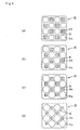
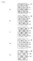
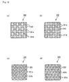
- Figs. 4(a) to 4(d), Figs. 5(a) to 5(f), and Figs. 6(a) to 6(d) are cross-sectional views each showing schematically a part of a cross-section of a porous member constituting an aggregation type honeycomb structural body according to the present invention. Since shapes in cross-sections of large-capacity through holes and small-capacity through holes in an integral type honeycomb structural body are in the same combination as that of the aggregation type honeycomb structural body, shapes in the cross-sections of large-capacity through holes and small-capacity through holes in the honeycomb structural bodies of the present invention will be described by referring to these figures.
- an aperture ratio (a cross-sectional area of a large-capacity through hole/a cross-sectional area of a small-capacity through hole) is almost 1.55, it is almost 2.54 in Fig. 4(b), it is almost 4.45 in Fig. 4(c), and it is almost 6.00 in Fig. 4(d), respectively. Furthermore, all the aperture ratios are almost 4.45 in Figs. 5(a), 5(c), and 5(e), while all of them are almost 6.00 in Figs. 5 (b), 5 (d), and 5 (f), respectively. Moreover, the aperture ratio is almost 1.55 in Fig. 6(a), it is almost 2.54 in Fig. 6(b), it is almost 4.45 in Fig.
- each of all the large-capacity through holes has a cross-section of an octagonal shape, while each of all the small-capacity through holes has a cross-section of an quadrangular shape, and they are located alternately.
- each cross-sectional area of the small-capacity through holes is changed, and each cross-sectional area of the large-capacity through holes is slightly changed, its aperture ratio can be easilymodified arbitrarily.
- aperture ratios of the honeycomb structural bodies shown in Figs. 5 and 6 may be arbitrarily modified.
- the compression strength of the A axis is calculated as follows. That is: In a honeycomb shape, a three-dimensional structure containing at least two planes perpendicular to the throughhole (more preferably, a rectangular parallelepiped with the rest four planes being cut in parallel with each other or a cubic shape) is cut out, and this is placed with the through hole being set perpendicular to the base, and load pressures are applied from above in a sandwiched manner, so that the strength is calculated based upon the load at the time of breakage.
- an isostatic strength means a strength at which destruction appears in the case when a static pressure is applied to a honeycomb structural body from a surrounding area.
- a cross-sectional area in a honeycomb shape is not changed from a flow-in side to a flow-out side of exhaust gases. This is because when a cross-sectional area of a through hole is changed, for example, in a state of the compression strength as mentioned above, a decrease in the compression strength is caused, so that it becomes difficult to manufacture a honeycomb structural body in accordance with compression molding.
- honeycomb structural bodies 160 and 260 shown in Figs. 5(a) and 5 (b) shapes in cross-sections of large-capacity through holes 161a and 261a are pentagonal shapes wherein three angles in each pentagon are almost right angles, while shapes in cross-sections of small-capacity through holes 161b and 261b are quadrangles wherein they are arranged in such that two small quadrangles occupies portions opposed obliquely to each other.
- Honeycomb structural bodies 170 and 270 shown in Figs. 5(c) and 5 (d) are obtained by modifying shapes in a cross-section shown in each of Figs.
- a curve defining the partition wall shared in common by the large-capacity through hole 171a and the small-capacity through hole 171b, or the partition wall shared in common by the large-capacity through hole 271a and the small-capacity through hole 271b which corresponds to a quarter circle is illustrated herein.
- a shape wherein its aperture ratio becomes the minimum is given by almost a shape shown in Fig. 5(c), and the aperture ratio in this case is almost 3.66.
- large-capacity through holes 181a and 281a as well as small-capacity through holes 281b and 281b are quadrangles (rectangles), respectively.
- it may be configured such that two large-capacity through holes are combined with two small-capacity through holes so as to obtain an substantially square shape configuration. In this arrangement, a deformation of a honeycomb structural body can be prevented at the time of manufacturing the same.
- a total length (a) of a wall portion shared in common by a large-capacity through hole and the adjacently located large-capacity through hole in a cross-section perpendicular to the length direction and a total length (b) of a wall portion shared in common by a large-capacity through hole and the adjacently located small-capacity through hole in a cross-section perpendicular to the length direction vary with an almost constant relation in accordance with a variation of the aperture ratio.
- a lower limit is 1.55, and 2.0 is more preferable with respect to a ratio of an area in a cross-section of the large-capacity through hole to that of the small-capacity through hole.
- an upper limit of the above-mentioned ratio is preferably 2.75, more preferable is 2.54, and the most preferable is 2.42.
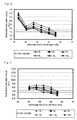
- regeneration limit value means a collection amount (g/l) of particulates wherein when a much more amount of particulates is collected, there is such fear that cracks and the like appear in a honeycomb structural body, resulting in a damage of the honeycomb structural body in case of regeneration therefor. Accordingly, when such regeneration limit value increases, an amount of particulates which can be collected before a required regeneration is carried out may be increased, so that aperiodof time up to the required regeneration can be prolonged.
- a catalyst may be supported by a surface and/or an inside of a partition wall separating a number of through holes from one another.
- An example of the catalyst includes the ones by which CO, HC, and NO x contained in exhaust gases can be converted.
- a honeycomb structural body according to the present invention it is served for a honeycomb structural body for collectingparticulates in exhaust gases, and at the same time, served for a catalyst converter for converting CO, HC, and NO x contained in the exhaust gases.
- Catalysts which can be supported by a honeycomb structural body of the present invention are not limited to the above-mentioned noble metals, but any catalyst may be supported so far as such catalyst can purify CO, HC, NO x and the like contained in exhaust gases.
- Either the above-mentioned catalyst may be supported on surfaces of particles constituting a honeycomb structural body of the invention while remaining air pores, or it may be supported on the wall portion with a certain thickness thereof. Furthermore, the above-mentioned catalyst may be supported uniformly on surfaces of the wall portion of through holes, or it may be supported on a certain place in a concentrated state. Particularly, when the above-mentioned catalyst is supported on surfaces of the wall portion in through holes on an inlet side, surfaces of particles in the peripheries of these surfaces, or both of these surfaces, combustion of particulates can be efficiently carried out, because the particulates are easily in contact with the above-mentioned catalyst.
- convex portions and/or concave portions for supporting a catalyst are/is formed inside a number of through holes in parallel to the length direction thereof in the honeycomb structural body.
- Convex portions or concave portions have been previously formed on the above-mentioned the partition wall.
- the portions of the partition wall for separating large-capacity through holes 111a, 121a, 131a, and 141a from one another are provided with convex portions 114, 124, 134, and 144, respectively.
- Each cross-section of the large-capacity through holes 111a, 121a, 131a, and 141a has an octagonal shape, if the convex portions 114, 124, 134, and 144 are ignored.
- each cross-section of small-capacity through holes 111b, 121b, 131b, and 141b has a quadrangular shape.
- the shape of the convex portions is not specifically limited, but it is desired that the shape has a shape by which droplets can be easily maintained, and at the same time a strength of a certain degree can be ensured. Specifically, it is desired that the shape has a shape which widens towards the base thereof. Moreover, it is desirable that each of the convex portions is continuously formed from the end of an inlet side to the end of an outlet side in the honeycomb structural body, whereby a high strength can be obtained, besides it becomes possible to manufacture such convex portions by extrusion forming.
- a height of the above-mentioned convex portion is not specifically limited, it is desired that the height is 0.02 to 6.0 times higher than a thickness of a partition wall separating adj acently located large-capacity through holes from one another.
- the height is less than 0.02 times thicker than the thickness, there is a case where a sufficient amount of a catalyst cannot be supported on the convex portion and the peripheries thereof, while it exceeds 6. 0 times thicker thickness, a strength of the convex portion becomes insufficient, so that there is a case where the convex portion is damaged by a pressure and the like of exhaust gases.
- the shape of the concave portions is not specifically limited, but it is desired that the shape has a shape by which droplets can be easily maintained. Specifically, it is desired that the shape has a recessed or grooved shape. Moreover, it is desirable that each of the concave portions is continuously formed from the end of an inlet side to the end of an outlet side in the honeycomb structural body, whereby it becomes possible to manufacture such concave portions by extrusion forming.
- a depth of the above-mentioned concave portion is not specifically limited, it is desired that the depth is 0.02 to 0.4 times deeper than a thickness of a partition wall separating adj acently located large-capacity through holes from one another.
- the depth is less than 0.02 times deeper thickness, there is a case where a sufficient amount of a catalyst cannot be supported on the convex portion and the peripheries thereof, while it exceeds 0.4 times deeper thickness, a strength of the partition wall becomes insufficient, so that there is a case where the partition wall is damaged by a pressure and the like of exhaust gases.
- each single convex portion or concave portion, or a plurality of convex portions or concave portions may be formed per each single partition wall for separating the respective adj acently located large-capacity through holes from one another.
- the convex portions and/or concave portions for supporting a catalyst are formed on the portions of the partition wall shared in common by inlet side-through holes. In this situation, particularly, a catalyst may be selectively applied easily.
- An example of the above-mentioned catalyst includes noble metals such as platinum, palladium, and rhodium.
- a catalyst comprising these noble metals is a so-called three-way catalyst.
- a honeycomb structural body according to the present invention wherein such three-way catalyst has been supported has the same functions as that of a heretofore well-known catalyst converter. Accordingly, a detailed explanation of a case where the honeycomb structural body of the present invention functions as a catalyst converter is omitted.
- a cross-sectional area of the honeycomb structural body is not varied from its flow-in side to its flow-out side of exhaust gases. It is because an improvement of compression strength and the like can be achieved, and it becomes easy to manufacture the honeycomb structural body by means of extrusion forming in accordance with such arrangement as described above.
- a honeycomb structural body according to the present invention has an isostatic strength of 7 MPa or more, and 9 MPa or more is more desirable.
- isostatic strength is also called by the name of isotropic pressure fracture strength which means a strength in the case when a honeycomb structural body is destroyed by applying an isotropic pressure such as hydrostatic pressure to the honeycomb structural body.
- the above-mentioned honeycomb structural body has a compression strength along A-axis of 18 MPa or more, and more desirable is 25 MPa or more.
- a compression strength along A-axis is within the above specified range, excellent durability is obtained with respect to regeneration of particulates.
- Materials are not specified for the honeycomb structural bodies according to the present invention.
- An example of the materials includes nitride ceramics such as aluminum nitride, silicon nitride, boron nitride, and titanium nitride; carbide ceramics such as silicon carbide, zirconium carbide, titanium carbide, tantalum carbide, and tungsten carbide; and oxide ceramics such as alumina, zirconia, cordierite, and mullite.
- Thematerial maybe composedof two or more components, for example, it may be a composite material of silicon and silicon carbide, or aluminum titanate.
- a further example of the material includes Fe ⁇ Cr ⁇ Al-base metals such as spinel, lithium aluminum silicate, chromium-base stainless steels, and chromium-nickel base stainless steels as well as metallic silicon and the like.
- a major constituent thereof is at least one member selected from SiC, Si 3 N 4 , aluminum titanate, cordierite, mullite, alumina, spinel, lithium alumina silicate, Fe ⁇ Cr ⁇ Al-base metals, and metallic silicon.
- silicon carbide having high thermal resistance, high heat conductivity and being excellent in mechanical properties is desirable.
- the metallic material is a porous member.
- an example of porous metallic member includes a structural body constituted by metal fibers made of a metal as mentioned above in a three-dimensionally involved state, a structural body made of a metal as mentioned above wherein air pits are formed by the use of a pore forming agent, and a structural body prepared by sintering a metal powder made of a metal as mentioned above so as to remain pores in the structural body.
- honeycomb structural body When a material for the above-mentioned honeycomb structural body is principally made of a metal, a honeycomb structural body having a lower pressure loss can be realized, even if the whole structure of the honeycomb structural body is made to be high porosity, because a sufficient strength can be ensured. Furthermore, in this case, an appearance of a gap and the like between the honeycomb structural body and a casing (metallic container) due to a difference in thermal expansion of them can be more effectively prevented. Moreover, since metal is excellent in thermal conductivity, its thermal equality can be improved, whereby a purification ratio of particulates can be improved in a regeneration process. In addition, since its thermal capacity becomes small, it becomes possible to rapidly raise a temperature by means of exhaust heat discharged from an internal combustion engine. It may be considered that when the honeycomb structural body is used in such a manner that it is installed immediately beneath an engine, and exhaust heat from the engine is effectively utilized, so that such honeycomb structural body is superior.
- honeycomb structural body As mentioned above will be described.
- a structure of the honeycomb structural body is an integral type honeycomb structural body as shown in Fig. 3 and the whole of which is constituted by a single sintered body
- extrusion forming is carried out by the use of a raw material paste containing ceramics as mentioned above as its major constituent to manufacture a formed body having the same configuration as that of the honeycomb structural body 30 shown in Fig. 3.
- the above-mentioned raw material paste is not specifically limited, but any raw material paste is applicable so far as the resulting porous block after manufacturing has a porosity of 20 to 80%.
- An example of the raw material pastes includes a mixture prepared by adding a binder and a dispersant liquid to a powder of ceramics as mentioned above.
- the above-mentioned binder is not specifically limited.
- An example of which includes methyl cellulose, carboxymethylcellulose, hydroxyethyl cellulose, polyethylene glycol, phenolic resins, epoxy resins and the like.
- a blending quantity of the binder is desirably 1 to 10 parts by weight with respect to 100 parts by weight of a ceramic powder usually based thereon.
- the above-mentioned dispersant liquid is not specifically limited, and an example of which includes organic solvents such as benzene; alcohols such as methanol; and water.
- a suitable amount of the dispersant liquid is blended in such that a viscosity of a raw material paste is within a certain range.
- a molding auxiliary may be added to the above-mentioned raw material paste based on necessity.
- the molding auxiliary is not specifically limited, and an example of which includes ethylene glycol, dextrin, fatty acid soap, polyalcohols and the like.
- a pore forming agent such as a balloon containing oxide-base ceramics as its component and being micro hollow sphere, spherical acryl particles, and graphite may be added based on necessity.
- the above-mentioned balloon is not specifically limited, and an example of which includes alumina balloon, glass micro balloon, shirasu balloon, fly ash balloon (FA balloon), mullite balloon and the like. Among others, the fly ash balloon is desirable.
- a metal such as silicon may be blended with the above-mentioned raw material paste, or a raw material paste containing a metal as its major constituent may be used.
- the above-mentioned formed body is dried by the use of a microwave dryer, a hot-air dryer, a dielectric dryer, a reduced-pressure dryer, a vacuum dryer, freeze dryer or the like, and then, each of predetermined through holes in the formed body is filled with a sealing material(plug) paste turning into a plug thereby to implement pore-sealing treatment upon the through holes.
- a material for the sealing material (plug) paste is not specifically limited, but any material is applicable so far as the resulting plug obtained through the following step has 20 to 80% porosity. For instance, the same material as the above-mentioned rawmaterial paste is applicable.
- such material is prepared by adding a lubricant, a solvent, a dispersant, and a binder to a powder used in the raw material paste. Because of this modification, it becomes possible to prevent sedimentation of particles in the sealing material paste in the middle of the mouth sealing treatment.
- a honeycomb structural body made of porous members and the whole of which is constituted by a single sintered body can be manufactured.
- a condition applied heretofore in the course of manufacturing a honeycomb structural body composed of porous members may be applied to the above-mentioned predetermined condition for degreasing and sintering the dried body.
- a raw material paste containing the above-mentioned ceramics as its major constituent is subjected to extrusion forming to produce a raw formed body having a shape of the porous member 20 shown in Figs. 2 (a) and 2(b).
- the raw material paste the same raw material paste as that explained in the above-mentioned aggregation type honeycomb structural body is applicable.
- a metal such as silicon powder may be blended with the raw material paste, or a raw material paste containing a metal as its major constituent may be used.
- each of predetermined through holes in the dried body is filled with a sealing material (plug) paste turning into a plug thereby to implement pore-sealing treatment upon the through holes.
- a sealing material (plug) paste the same sealing material (plug) paste as that explained in the above-mentioned integral type honeycomb structural body is applicable.
- the same manner as that of the above-mentioned integral type honeycomb structural body is applicable except that target through holes to be filled with a sealing material (plug) paste are different from those of the aggregation type honeycomb structural body.
- the dried body after the pore-sealing treatment is degreased and sintered under a predetermined condition, whereby porous members wherein a plurality of through holes are placed in parallel with one another in the length direction through the partition wall can be manufactured.
- a predetermined condition for degreasing and sintering the above-mentioned raw formed body a condition used heretofore in case of manufacturing a honeycomb structural body configured by binding a plurality of porous members through a sealing material layer, respectively, is applicable.
- the porous member 20 is placed on a base in an tilted manner, the upper cross-section of the pedestal being in V-shaped so as to be capable of stacking the porous member 20 while maintaining an obliquely inclined state thereof. Thereafter, two sides of the porous member faced to the upper direction are coated with a sealing material paste turning into the sealing material layer 14 with a uniform thickness to form the sealing material layers. A step for laminating sequentially another porous member 20 on the sealing material paste layer is repeated to produce a laminated body of a predetermined size and composed of rectangular pillar-shaped porous members 20.
- a material for constituting the sealing material paste is the same as that explained in the honeycomb structural body according to the present invention, so that the explanation therefor is omitted herein.
- the laminated body composed of the porous members 20 is heated to dry and cure the sealing material paste layer to obtain the sealing material layer 14. Thereafter, the outer circumference of the laminated body is cut out into a shape as shown in Fig. 3 by means of, for example, a diamond cutter, whereby the porous block 15 is formed.
- a honeycomb structural body configured by binding a plurality of the porous members through the sealing material layer can be manufactured.
- Any of the honeycomb structural bodies thus manufactured has a cylindrical shape, and the structures thereof are those shown in Figs. 1 and 3.
- a honeycomb structural body according to the present invention relates to the one composed of metallic lamination members wherein the lamination members are laminated in the length direction in such that through holes are superposed one another, first, a porous metallic sheet having a thickness of around 0.1 to 20 mm and made of a metal is subjected to laser beam machining, whereby a honeycomb-shaped laminated body wherein holes are formed on almost whole the surface of the laminated body with each almost equal distance, and through holes are formed at a high density is manufactured.
- FIG. 7 is a cross-sectional view showing schematically an example of an exhaust gas purifying device for vehicles wherein a honeycomb structural body according to the present invention is installed.
- an exhaust gas purifying device 600 is mainly configured by a honeycomb structural body 60 of the present invention, a casing 630 for covering the outer circumference of the honeycomb structural body 60, a holding seal member 620 disposed between the honeycomb structural body 60 and the casing 630, and a heating means 610 located at a flow-in side of exhaust gases in the honeycomb structural body 60 wherein an introduction pipe 640 linked to an internal combustion engine such as an engine is connected to an end of the casing 630 to the side of which the exhaust gases are introduced, and an exhaust pipe 650 linked to the outside is connected to the other end of the casing 630.
- arrows in Fig. 7 indicate a flow of the exhaust gases.
- the honeycomb structural body 60 in Fig. 7 may be either the honeycomb structural body 10 shown in Fig. 1 or the honeycomb structural body 30 shown in Fig. 3.
- exhaust gases discharged from an internal combustion engine such as an engine are introduced into the casing 630 through the introduction pipe 640, and the exhaust gases pass through a wall portion (the partition wall) via through holes in the honeycomb structural body 60, whereby particulates contained in the exhaust gases are collected by the wall portion (the partition wall) to be purified, and then, the exhaust gases thus purified are discharged to the outside through the exhaust pipe 650.
- a regeneration process of the honeycomb structural body 60 is performed.
- a gas heated by the heating means 610 is allowed to flow into the interiors of the through holes to heat the honeycomb structural body 60, whereby the particulates deposited on the wall portion (the partition wall) are burned off to remove them.
- particulates may be burned off and removed.
- An exhaust gas purifying device wherein the honeycomb structural body according to the present invention is applied belongs also to the present invention.
- the resulting raw formed body was dried by the use of a microwave dryer to obtain a dried body. Thereafter, predetermined through holes in the dried body were filled with a filler paste having the same composition as that of the raw formed body, and dried again by using the dryer. Then, the thus driedproduct was degreased at 550°C for 3 hours under an oxidative atmosphere to obtain a degreased body.
- the degreased body was heated under the condition of at 1400°C for 2 hours in an argon atmosphere to melt monocrystalline silicon, and silicon carbide particles were joined one another with silicon to manufacture a porous member having 45% porosity, 10 ⁇ m average pore diameter, and 34.3 mm ⁇ 34.3 mm ⁇ 305 mm dimension.
- porous members were bound by the use of a heat-resistant sealing material paste containing 30% by weight of alumina fibers having 0.2 mm fiber length, 21% by weight of silicon carbide particles having 0.6 ⁇ m average particle diameter, 15% by weight of silica sol, 5.6% by weight of carboxymethylcellulose, and 28.4% by weight of water in accordance with the manner explained by referring to Fig. 5, and in succession, the resulting bound porous members were cut out by the use of a diamond cutter to form a cylindrical porous block having 190 mm in diameter. In this case, it was arranged in such that a thickness of a sealing material layer for binding the porous members was 1 mm.
- a sealing material paste layer having 1.0 mm thickness was formed on the outer circumferential area of the porous block by using the sealing material paste.
- the sealing material paste layer thus obtained was dried at 120°C to manufacture a filter of a cylindrical honeycomb structural body having a filter volume, and an aperture ratio on the inlet side of the filter shown in Table 1.
- a degreased body was prepared in accordance with the same manner as that of Examples 21 to 23 except that a metallic silicon powder having 4 ⁇ m average particle diameter was wet-mixed to prepare a raw material paste.
- the degreased body was heated under the condition of at 1000°C for 2 hours in an argon atmosphere to manufacture a porous member having 45% porosity, 10 ⁇ m average pore diameter, and 34.3 mm ⁇ 34.3 mm ⁇ 305 mm dimension.
- the porous members were bound in accordance with the same manner as that of Examples 21 to 23 to manufacture a filter of a cylindrical honeycomb structural body having 190 mm diameter.
- Porous ceramic members were manufactured in accordance with the same manner as that (1) of Example 1 except that each shape of large-capacity through holes was selected to be a rectangle, while each shape of small-capacity through holes was selected to be a rectangle (square shape depending on circumstances) in each cross-sectional shape of the porous ceramic members as shown in Figs. 5(e) and 5(f), and each aperture ratio on the inlet side of the porous ceramic members was made to be each of values indicated in Tables 2 and 3.
- Porous ceramic members were manufactured in accordance with the same manner as that of Examples 24 to 26 except that each aperture ratio on the inlet side after sintering the porous ceramic member was made to be each of the values indicated in Table 4.
- Filters of honeycomb structural bodies each having a volume indicated in Table 4 were manufactured by using the resulting porous ceramic members, respectively, in accordance with the same manner as that of Examples 24 to 26 except that a heat-resistant sealing material (adhesive) paste containing 30% by weight of alumina fibers having 20 ⁇ m fiber length, 21% by weight of silicon carbide particles having 0.6 ⁇ m average particle diameter, 15% by weight of silica sol, 5.6% by weight of carboxymethylcellulose, and 28.4% by weight of water was used as a sealing material (adhesive) paste, and a sealing material paste prepared by blending and kneading 23.3% by weight of ceramic fibers made of alumina silicate (shot content: 3%, fiber length: 5 to 100 ⁇ m), 30.2% by weight of silicon
- Fig. 8 is a graph indicating a relation between a filter volume (a volume of a honeycomb structural body) (L) and an aperture ratio on an inlet side in the filters (honeycomb structural bodies) relating to examples, comparative examples, and reference examples.
- the results of the filters relating to the examples are plotted as points within a pentagon A B C D E shown in the figure, and they exhibit preferable values in also the following measurement.
- Fig. 9 is a graph indicating a relation between a product obtained from a aperture ratio on the inlet side and a filter volume, and a discharge amount.
- a honeycomb structural body wherein a volume Y (L), an aperture ratio X (%) on the inlet side, and a discharge amount V (L) have the relation represented by the above-mentioned inequality (3) is within a range sandwiched in between the upper and lower functions.
- each filter of a honeycomb structural body prepared in the examples and the comparative examples was placed in an exhaust gas passage for applying as an exhaust gas purifying device.
- the engine was driven at 3000 min -1 rotational frequency and 50 Nm torque for a predetermined period of time to collect a predetermined amount of particulates.
- the engine was driven at 4000 min -1 rotational frequency and applied a full load, so that when a filter temperature came to be constant at around 700°C, the engine was driven at 1050 min -1 rotational frequency and 30 Nm torque, whereby the particulates were forcibly burned off.
- An experiment for such regeneration process was carried out while changing a collection amount of particulates, whereby it was examined whether or not cracks appear on a filter.
- the experiment was made upon the respective examples, comparative examples, and test examples wherein the maximum amount of particulates based on which cracks do not appear was made to be a regeneration limit value, and the results thereof are shown in the following Tables 1 to 4.
- a relation between an aperture ratio on the inlet side of a filter and a regeneration limit value was indicated with respect to each filter volume in a graph of Fig. 10 wherein filters have the cross-sectional shapes shown in Figs. 4 (a) to 4 (d), respectively; the relation was indicated also in a graph of Fig. 11 wherein filters have the cross-sectional shapes shown in Figs. 5 (a) and 5 (b), respectively; the relation was indicated also in a graphical representation of Fig. 12 wherein filters have the cross-sectional shapes shown in Figs. 5(e) and 5(f), respectively; and the relation was indicated also in a graph of Fig. 13 wherein filters have the cross-sectional shapes shown in Figs.
- each filter of a honeycomb structural body prepared in the examples and the comparative examples was placed in an exhaust gas passage for applying as an exhaust gas purifying device.
- a thermometer was set out in the central portion of the filter, and in this state, the engine was driven at 3000 min -1 rotational frequency and 50 Nm torque to collect 8 g/L of particulates. Thereafter, the engine was driven at 1250 min -1 rotational frequency and 60 Nm torque, so that when its central temperature came to be constant, it was maintained for one minute. Thereafter, post injection was conducted to utilize an oxidation catalyst positioned at anterior of the filter, whereby an exhaust air temperature was raised to burn off the particulates.
- a condition for the post injection was set out in such that a central temperature of the honeycomb structural body became almost constant at 600°C during one minute after the post injection was started.
- a temperature was constant at 1250 min -1 rotational frequency and 60 Nm torque, and a total period of time until a flammability peak appeared in the central temperature of a honeycomb structural body as a result of burning out particulates in the following post injection were measured, whereby thermal responsiveness was evaluated, and the results thereof are shown in Tables 1 to 4.
- the filters of the examples exhibit more preferable values than those of the filters of the Comparative examples with respect to all of regeneration limit value, thermal responsiveness, and compression strength and isostatic strength of a filter.
- a volume Y and an aperture ratio X on the inlet side of each filter comprising the above-mentioned honeycomb structural bodies have a relation represented by the above-mentioned inequality (1), a long life time can be achieved while maintaining a compact filter size (each size of the honeycomb structural bodies).
- such filter is excellent in mechanical strength and thermal responsiveness, a critical value of cracks is high, and it results in excellent durability.
Landscapes
- Physics & Mathematics (AREA)
- Geometry (AREA)
- Chemical & Material Sciences (AREA)
- Chemical Kinetics & Catalysis (AREA)
- Engineering & Computer Science (AREA)
- Mechanical Engineering (AREA)
- Combustion & Propulsion (AREA)
- General Engineering & Computer Science (AREA)
- Organic Chemistry (AREA)
- Materials Engineering (AREA)
- Life Sciences & Earth Sciences (AREA)
- Geology (AREA)
- Filtering Of Dispersed Particles In Gases (AREA)
- Filtering Materials (AREA)
- Catalysts (AREA)
- Exhaust Gas After Treatment (AREA)
- Processes For Solid Components From Exhaust (AREA)
Abstract

Description
- This application claims benefit of priority based on
Japanese Patent Application No. 2004-046949 filed on February 23, 2004
The present invention relates to a honeycomb structural body and an exhaust gas purifying device used for the purpose of removing particulates and the like in exhaust gases discharged from an internal combustion engine such as a diesel engine. - In recent years, particulates, contained in exhaust gases discharged from internal combustion engines of vehicles such as buses, trucks, construction machines and the like, have raised serious problems as these particulates are harmful to the environment and the human body. There have been proposed various honeycomb structural bodies used as ceramics filters which allow exhaust gases to pass through porous ceramics to collect particulates in the exhaust gases, so that the exhaust gases can be purified.
- Heretofore, there is disclosed a ceramic filter wherein through holes an end of each of them on a side from which exhaust gases flow out is sealed (hereinafter referred optionally to as "through hole on flow-in side") are made to be through holes of a large volume (hereinafter referred optionally to as "large-capacity through hole"), while through holes an end of each of them on a side to which exhaust gases flow in is sealed (hereinafter referred optionally to as "through hole on flow-out side") are made to be through holes of a small volume (hereinafter referred optionally to as "small-capacity through hole"), whereby an aperture ratio on the flow-in side of the exhaust gases is made relatively larger than that of the flow-out side of the exhaust gases.
- Fig. 18 is a cross-sectional view showing schematically a cross-section perpendicular to the length direction of a conventional exhaust gas filter.
This exhaust-gas filter 60 has a cross-sectional structure in which squares, each smaller than each of square shapes constituting the checker board pattern, are placed on intersections of the checker board pattern, and this structure is constituted by small-capacity throughholes 61b corresponding to the smaller squares and large-capacity throughholes 61a located on the periphery thereof, with thepartition wall - Figs. 19(a) to 19(d) are cross-sectional views each showing schematically a cross-section perpendicular to the length direction of another conventional exhaust filter.
Theseexhaust gas filters 300 to 330 are composed of large-capacity throughholes holes partition wall
Any of the portions of thepartition wall holes holes holes - Furthermore, a filter wherein a cell pitch of large-capacity through holes is made to be almost 1.0 to 2.5 mm is disclosed as another prior art (see Patent Document 8).
Besides, a filter wherein a volume ratio in large-capacity through holes is 60 to 70%, a volume ratio in small-capacity through holes is 20 to 30%, and a cell pitch of the large-capacity through holes is almost 2.5 to 5.0 mm is also disclosed (see Patent Document 9). - Fig. 20 is a cross-sectional view showing schematically a cross-section perpendicular to the length direction (hereinafter optionally referred simply to as "cross-section") of each of the above-mentioned
filters 200. In thefilter 200, small-capacity throughholes 202 each having a triangular cross-section are disposed around each large-capacity throughhole 201 having a hexagonal cross-section. - Moreover, a filter having 40 to 120% of a percentage of a ratio of a gross area in cross-sections of small-capacity through holes with respect to a gross area in cross-sections of large-capacity through holes is also disclosed (see
Patent Documents 10 and 11).
Fig. 21 is a cross-sectional view that schematically shows a cross-section perpendicular to the length direction of such a honeycomb structural body, and in afilter 210, small-capacity throughholes 212, each having an laterally elongated hexagonal shape in its cross section, are placed on the periphery of a large-capacity throughhole 211 having a right hexagonal shape in its cross section. Moreover, in the periphery of the circumference thereof, the large-capacity throughholes 211 having a right hexagonal shape and large-capacity throughholes 213 having a trapezoidal shape are placed also in parallel with each other.
Moreover, a filter wherein the number of through holes on its flow-in side is made larger than that of its flow-out side, whereby an aperture ratio on the flow-in side of exhaust gases is made to be relatively larger than that of the flow-out side of the exhaust gases is also disclosed (For example, see Fig. 3 of Patent Document 10). - On one hand, a technique for adjusting a thickness of a wall, and physical properties of a filter are also disclosed (see
Patent Documents 12 and 13). A filter containing through holes having square and rectangular cross-sections is also disclosed (see Patent Document 14). - A filter containing through holes having two types of shapes, among others, octagonal and quadrangular shapes is also disclosed (see
Patent Documents 15 and 16). Another filter containing through holes having two types of shapes, i.e. relatively large square and small square shapes is disclosed (see Patent Document 17). - In addition, a honeycomb filter having 1.1 to 15 times higher aperture ratio on a flow-in side of exhaust gases than that of a flow-out side of the exhaust gases is also disclosed (see Patent Document 18).
- In all the filters disclosed in the above-mentioned prior arts, since an aperture ratio on a flow-in side of exhaust gases is made relatively larger than that of a flow-out side thereof as compared with a filter wherein an aperture ratio on a flow-in side of exhaust gases is made to be equal to that of a flow-out side thereof, it becomes possible to increase a critical amount for collecting particulates and to prolong a period of time up to a required regeneration in the case when these filters are used for purifying exhaust gases.
- Patent Document 1:
US Patent No. 4417908
Patent Document 2:JP-A 58-196820 (1983
Patent Document 3:US Patent No. 4364761
Patent Document 4:JP-A 56-124417 (1981
Patent Document 5:JP-A 62-96717 (1987
Patent Document 6:US Patent No. 4276071
Patent Document 7:JP-A 56-124418 (1981
Patent Document 8: J UM-A56-187890 microfilm (1981) (J UM-A 58-92409 (seepage 4, Fig.6)
Patent Document 9:JP-A 5-68828 (1993 Japanese Patent No. 3130587
Patent Document 10:JP-A 2001-334114
Patent Document 11: International Publication No.WO02/100514
Patent Document 12:US Patent No. 4416676
Patent Document 13:US Patent No. 4420316
Patent Document 14:JP-A 58-150015 (1983
Patent Document 15:French Patent No. 2789327
Patent Document 16:International Publication No. WO02/10562
Patent Document 17:International Publication No. WO03/20407
Patent Document 18:International Publication No. WO03/80218 - However, it has been found that these filters exhibit a comparatively high initial pressure loss as compared with a usual filter (namely, a filter having the same aperture ratio on flow-in and flow-out sides of exhaust gases).
In addition, a strength of a filter decreases with increase of an aperture ratio of a flow-in side of exhaust gases in the filter. Thus, it has been found that cracks appear easily, when a thermal shock arises due to vibration of an engine in case of operation, or combustion of particulates in case of regeneration therefor. - On one hand, when a volume of a filter is allowed to increase without changing an aperture ratio on an inlet side, whereby a specific surface anda total volume of a throughhole (filtration area) are also allowed to increase, a pressure loss can be reduced.
However, when a volume of a filter is increased, it becomes difficult to maintain a space for locating the filter in the periphery of an internal combustion engine, further, thermal responsiveness decreases with increase in the volume, or it becomes difficult to burn off soot, and cracks appear easily due to thermal shock. Accordingly, it is not an effective countermeasure to simply increase a volume in a filter for solving the above-mentioned problems. - The present inventor studies eagerly to solve the above-mentioned problems. As a result, it has been found that a life of a honeycomb structural body can be prolonged while keeping a size of the honeycomb structural body in a compact state so far as a predetermined relation is satisfied between a volume of the honeycomb structural body and an aperture ratio on an inlet side of the honeycomb structural body, and that the resulting honeycomb structural body exhibits high critical value for the appearance of cracks because it is excellent in thermal responsiveness, so that a reliably excellent honeycomb structural body is obtained. Thus, the present invention was completed.
In addition to the above description, it has been further found that cracks are less likely to appear in a honeycomb structural body according to the present invention so far as a predetermined relation is satisfied among the volume of the above-mentioned honeycomb structural body, the above-mentioned aperture ratio, and a discharge amount of an internal combustion engine, and as a result, performance of the honeycomb structural body can effectively be utilized. - Namely, a honeycomb structural body according to the present invention is a pillar-shaped honeycomb structural body having a honeycomb structure that a number of through holes are placed in parallel with one another in the length direction with a wall portion interposed therebetween and one of ends of each through hole is sealed, wherein a relation between a volume Y (L) of the honeycomb structural body and an aperture ratio X (%) on an inlet side satisfies the following inequality (1):

- In the honeycomb structural body according to the present invention, desirably, the relation between the volume Y (L) of the honeycomb structural body and the aperture ratio X (%) on the inlet side satisfies the following inequality (2):

- Desirably, upon using the honeycomb structural body as a honeycomb structural body for purifying exhaust gases of an internal combustion engine, a relation among the volume Y (L) of the honeycomb structural body, the aperture ratio X (%) on the inlet side and a discharge amount V (L) of the internal combustion engine satisfies the following inequality (3):

- In the honeycomb structural body, desirably, the number of the throughholes comprise large-capacity through holes opened on a flow-in side of exhaust gases and each having a relatively large area in a cross-section perpendicular to the length direction thereof, and small-capacity through holes opened on a flow-out side of the exhaust gases and each having a relatively small area in the cross-section. Desirably, the number of the large-capacity through holes is substantially the same as that of the small-capacity through holes.
- In the honeycomb structural body, desirably, a plurality of pillar-shaped porous members each comprising a plurality of through holes placed in parallel with one another in the length direction with a partition wall interposed therebetween are bound to one another through a sealing material layer.
- In the honeycomb structural body, desirably, shapes of a number of through holes in their cross-sections perpendicular to the length direction include at least two or more types of shapes.
Desirably, shapes in cross-sections perpendicular to the length direction of the large-capacity through holes and/or the small-capacity through holes are polygonal, e.g., octagonal; and quadrangular shape. - In the honeycomb structural body, a ratio of cross-sectional areas of the large-capacity through holes with respect to cross-sectional areas of the small-capacity through holes is 1.55 to 2.75.
Desirably, peripheries of corners in cross-sections perpendicular to the length direction of the large-capacity through holes and/or the small-capacity throughholes are defined by a curved line. - In the honeycomb structural body, desirably, a distance between centers of gravity in the cross-sections perpendicular to the length direction of the adj acently located large-capacity through holes is equal to a distance between centers of gravity of the cross-sections perpendicular to the length direction of the adjacently located small-capacity through holes.
- In the honeycomb structural body, desirably, a catalyst is supported by a surface and/or an inside of the partition wall separating the number of through holes from one another.
Desirably, convex portions and/or concave portions are formed inside the number of through holes in parallel with the length direction thereof, and the convex portions and/or concave portions are formed on the portions of the partition wall, which is shared in common by inlet side-through holes.
Desirably, the convex portions and/or concave portions function as at least one of a region for supporting selective catalysts, a particulate collecting site, and a site for improving heat stress-resistance of the honeycomb structural body. - In the honeycomb structural body, desirably, an isostatic strength is 7 MPa or more, and a compression strength along an A-axis is 18 MPa or more.
- Desirably, a shape in a cross-section perpendicular to the length direction of the number of through holes: is constituted by a single shape; and composed of at least two types of cross-sectional areas.
- In the honeycomb structural body, desirably, a main component is at least one kind selected from SiC, Si3N4, aluminum titanate, cordierite, mullite, alumina, spinel, lithium aluminum silicate, Fe·Cr·Al-base metals, and metallic silicon.
Furthermore, the honeycomb structural body is desirably used for an exhaust gas purifying device of a vehicle. - According to the honeycomb structural body of the present invention, since the relation between the volume Y of the honeycomb structural body and the aperture ratio X on the inlet side satisfies of the above-mentioned inequality (1), a life of the honeycomb structural body can be prolonged while keeping a size thereof in a compact state. Besides, since the honeycomb structural body has an excellent mechanical strength and thermal responsiveness, high critical value for the appearance of cracks, so that it exhibits excellent reliability.
- A honeycomb structural body according to the present invention is a pillar-shaped honeycomb structural body having a honeycomb structure that a number of through holes are placed in parallel with one another in the length direction with a wall portion interposed therebetween and one of ends of each through hole is sealed, wherein
a relation between a volume Y (L) of the honeycomb structural body and an aperture ratio X (%) on an inlet side satisfies the following inequality (1):
- Herein, the aperture ratio X (%) on the inlet side means a percentage of a sum total of areas in inlet side-through holes with respect to an area of the whole end of the honeycomb structural body on the inlet side.
- The honeycomb structural body according to the present invention is a pillar-shaped honeycomb structural body having a honeycomb structure that a number of through holes are placed in parallel with one another in the length direction with a wall portion interposed therebetween and one of ends of each through hole is sealed.
The above-mentioned honeycomb structural body may be modified in such that a plurality of pillar-shaped porous members each comprising a plurality of through holes placed in parallel with one another in the length direction with a partition wall interposed therebetween are bound to one another through a sealing material layer (hereinafter referred optionally to as "aggregation type honeycomb structural body"), or such that whole the porous members are sintered so as to have an integral structure (hereinafter referred optionally to as "integral type honeycomb structural body"). In addition, the lamination members may be laminated in the length direction so as to superpose through holes one another in the honeycomb structural body. - Fig. 1 is a perspective view showing schematically an illustrative embodiment of aggregative type honeycomb structural body being an example of the honeycomb structural body according to the present invention. Fig. 2(a) is a perspective view showing schematically an example of a porous member a certain number of which constitutes the honeycomb structural body shown in Fig. 1, and Fig. 2(b) is a cross-sectional view taken along the line A-A of the porous member shown in Fig. 2(a).
- As shown in Fig. 1, in a honeycomb
structural body 10 according to the present invention, a plurality ofporous members 20 is bound to one another through a sealingmaterial layer 14 to constitute aporous block 15, and a sealingmaterial layer 13 for preventing exhaust gas leakage is formed around the aporous block 15. - In the
porous member 20, a number of through holes 21 are placed in parallel with one another in the length direction wherein a through hole 21 comprises two types of through holes, i.e. one of which is a large-capacity throughhole 21a having a relatively large area of a cross-section perpendicular to the length direction, and the other is a small-capacity throughhole 21b having a relatively small area of a cross-section perpendicular to the longitudinal section. The large-capacity throughhole 21a is sealed with aplug 22 at the end on an outlet side of exhaust gases in the honeycombstructural body 10, while the small-capacity throughhole 21b is sealed with theplug 22 at the end on an inlet side of the exhaust gases in the honeycombstructural body 10 wherein apartition wall 23 for separating these two types of through holes from one another functions as a honeycomb structural body. More specifically, exhaust gases flowing into the large-capacity throughholes 21a pass inevitably through thepartition wall 23 to flow out from the small-capacity throughholes 21b. - The honeycomb
structural body 10 as described above has a relation between its volume Y (L) and an aperture ratio X (%) on the inlet side of the large-capacity throughholes 21a which satisfies the following inequality (1):
- In general, when a honeycomb structural body is utilized by disposing it in a flow path of exhaust gases, ash starts to be accumulated from a rear (outlet side) of the honeycomb structural body. Because of such phenomenon, it is required to increase a volume in a through hole which is opened on an inlet side for suppressing a pressure loss, in other words, for prolong a life of the honeycomb structural body, even if the ash is accumulated for a long period of time. In this respect, in order to increase the volume in a through hole which is opened on the inlet side, it is required that: an aperture ratio on the inlet side is made to be high; and a volume of the honeycomb structural body is increased.
- However, when the aperture ratio becomes high, a density of the whole honeycomb structural body decreases. As a result, a regeneration limit value (the maximum accumulation amount of particulates at which any crack does not appear when particulates accumulated are burned off.) becomes low, so that a period of time up to a required regeneration becomes short.
On one hand, when a volume of the honeycomb structural body increases, a thermal capacity of the whole honeycomb structural body increases, resulting in poor temperature rising property of the whole honeycomb structural body. - On the other hand, firstly, a volume of the above-mentioned honeycomb structural body satisfying a relation represented by the above inequality (1) according to the present invention is limited to 19 (L) or less. Thus, by setting the upper limit of the volume of the honeycomb structural body as described above, deterioration in temperature rising property of the whole honeycomb structural body can be prevented.
- Furthermore, the
lower limit 35% and theupper limit 65% are set out in respect of an aperture ratio on an inlet side of a honeycomb structural body. When an aperture ratio on the inlet side is less than 35%, the weight of porous members constituting the honeycomb structural body becomes too heavy, whereby a thermal capacity increases, resulting in poor temperature rising property. Besides, each amount (volume) of wall portion increases, so that its pressure loss becomes easily high. On the other hand, when an aperture ratio on the inlet side exceeds 65%, the density of the whole honeycomb structural body decreases, so that a regeneration limit value decreases as mentioned above. - Moreover, ranges of an aperture ratio on the inlet side and a volume of a honeycomb structural body are set up so as to have a relation:

- In a honeycomb structural body according to the present invention, since a relation between an aperture ratio on an inlet side and a volume of the honeycomb structural body is established so as to satisfy the above-mentioned inequality (1), a volume of through holes opened on their inlet sides can be increased, whereby increase in a pressure loss is suppressed, so that a large amount of particulates and ash can be accumulated. In addition, decrease in a density of the whole honeycomb structural body can be suppressed, whereby decrease in a regeneration limit value can be prevented, so that the resulting honeycomb structural body is excellent in thermal responsiveness, and it results in having a long life time.
- In the honeycomb structural body according to the present invention, desirably, the relation between the volume Y (L) and the aperture ratio X (%) on the inlet side of the above-mentioned honeycomb structural body satisfies the following inequality (2) :

- In a honeycomb structural body satisfying a relation represented by the above-mentioned inequality (2), a volume of the honeycomb structural body is set out at a value of 2.5 L or more. When the volume is less than 2.5 L, a volume of the honeycomb structural body becomes small. In this case, when an aperture ratio or the like on an inlet side is increased so as to increase a total accumulation amount of particulates, cracks and the like appear easily.
Furthermore, even when the above-mentioned aperture ratio and the volume of a honeycomb structural body is in the above specified range, if the above-mentioned inequality (2) is not satisfied, it cannot be said that its regeneration limit value is sufficient. - According to a honeycomb structural body of the present invention, when a relation between an aperture ratio on the inlet side and a volume of the honeycomb structural body is set out so as to satisfy the above-mentioned inequality (2), increase in a pressure loss can be suppressed, whereby a much more amount of particulates and ash can be accumulated, besides decrease in a density of the whole honeycomb structural body can be suppressed, whereby decrease in a regeneration limit value can be more effectively prevented, resulting in excellent thermal responsiveness, and a long life time can be achieved.
- Moreover, in the case where the honeycomb structural body according to the present invention is used as a honeycomb structural body for purifying exhaust gases of an internal combustion engine, it is desired that a relation among a volume Y (L) of the honeycomb structural body, an aperture ratio X (%) on the inlet side thereof, and a discharge amount V (L) satisfies also the following inequality (3):

- When the above-mentioned honeycomb structural body is used as a filter for purifying exhaust gases of an internal combustion engine, a gas flow rate increases with increase in a discharge amount of the internal combustion engine. As a consequence, a resistance pressure of the honeycomb structural body increases.
In these circumstances, in order to decrease a pressure loss (exhaust pressure), it is sufficient to increase a volume of the honeycomb structural body. As mentioned above, however, when a volume of the honeycomb structural body increases, a thermal capacity of the whole honeycomb structural body increases, so that its thermal responsiveness decreases. In addition, in the case when a catalyst is supported on the honeycomb structural body, reactivity of the catalyst with exhaust gases becomes worse dependent upon a flow rate of the exhaust gases flowing into the honeycomb structural body.
In this respect, the honeycomb structural body having the relation represented by the above inequality (3) of the present invention has a suitable volume and a suitable aperture ratio on the inlet side with respect to a discharge amount of an internal combustion engine. Thus, the present invention can provide the optimum honeycomb structural body in response to a variety of internal combustion engines. - Although a porosity in a porous member is not specifically limited, but it is preferred that the porosity is around 20 to 80% in the case where the porous member is composed of ceramics as mentioned below. When a porosity is less than 20%, there is a case where the honeycomb structural body is easily clogged. On the other hand, when a porosity exceeds 80%, there is a case where a strength of a porous member decreases, so that it is easily broken.
- Moreover, in the case when the above-mentioned porous member is made of a metal as mentioned hereinafter, a desirable lower limit of the porosity is 50% by volume, while a desirable upper limit is 98% by volume. When a porosity is less than 50% by volume, there is a case where a deep-layer filtration cannot be achieved inside a wall portion, or a case where temperature rise characteristic becomes worse. On one hand, when a porosity exceeds 98% by volume, there is a case where a strength of a porous member decreases, so that it is easily destroyed. Amore preferable lower limit is 70% by volume, while a more preferable upper limit is 95% by volume.
- Furthermore, it is desired that the above-mentionedporous member has an average pore diameter of 1 to 100 µm. When an average pore diameter is less than 1 µm, there is a case of clogging by means of particulates. On one hand, if an average pore diameter exceeds 100 µm, there is a case where particulates pass through pores, so that the particulates cannot be collected, and thus, such porous member cannot function as a filter.
It is to be noted that a porosity or an average pore diameter may be measured by a heretofore well-known measuring method such as mercury porosimetry, gravimetric method, Archimedes method, and scanning electron microscope (SEM). - Although a particle diameter of a powder used in the case where such porous member as mentioned above is manufactured is not specifically limited, but desirable is a powder which exhibits less shrinkage in the following firing step. For instance, a mixture consisting of 100 parts by weight of a powder having some 0.3 to 50 µm average particle diameter and 5 to 65 parts by weight of a powder having some 0.1 to 1. 0 µm is desirable. This is because when powders each having the above-mentioned particle diameter are admixed with each other in the above-mentioned mix proportion, a porous member having the above-mentioned necessary properties can be manufactured.
- As the above-mentioned plug, desirable is that it is made from a porous material.
In a honeycomb structural body according to the present invention, since a porous member wherein the above-mentioned plug is used is made from a porous material, when the plug and the porous member are made from the same porous material, an adhesive strength of them can be improved. Besides, when a porosity of the plug is adjusted as in the case of the above-mentioned porous member, a thermal expansion coefficient of the above-mentioned porous member can be matched with that of the plug, whereby an appearance of a gap between a plug and a partition wall, or an appearance of cracks on a partition wall being in contact with a plug or an area which is in contact with a plug due to thermal stress in case of manufacturing or applying a honeycomb structural body can be prevented.
When the plug is made from a porous material, its material is not specifically limited, but, for example, the same materials as those from which the above-mentioned porous member is prepared may be listed. - In a honeycomb structural body according to the present invention, a sealing
material layer 13 and a sealingmaterial layer 14 are formed on the outer circumference of aporous block 15, and disposed betweenporous members 20. The sealingmaterial layer 14 thus disposed between theporous members porous members 20 with each other. On one hand, the sealing material layer(coat layer) 13 formed on the outer circumference of theporous block 15 is served for a sealing material for preventing leakage of exhaust gases from the outer circumference of theporous block 15 in the case where a honeycombstructural body 10 according to the present invention is located on an exhaust passage of an internal combustion engine. - A material constituting the above-mentioned sealing material layer is not specifically limited, but, for example, inorganic binders, organic binders, inorganic fibers and/or inorganic particles may be listed.
As mentioned above, a sealing material layer is disposed between porous members, or a sealing material layer is formed on the outer circumference of a porous block in a honeycomb structural body of the present invention. In this respect, these sealing material layers may be the same or different from one another. Furthermore, when these sealing material layers are made from the same material, a mix proportion of the material may be the same or different from one another. - An example of the inorganic binders includes silica sol, alumina sol and the like. They may be used alone, or may be used two or more of them together. Among the inorganic binders, silica sol is desirable.
An example of the organic binders includes polyvinyl alcohol, methyl cellulose, ethyl cellulose, and carboxymethylcellulose. They may be used alone, or may be used two or more of them together. Among the organic binders, carboxymethylcellulose is desirable. - An example of the inorganic fibers includes ceramic fibers of silica-alumina, mullite, alumina, and silica. They may be used singly, or in a combination of two or more of them. Among the inorganic fibers, alumina fibers and silica-alumina fibers are desirable.
- It is desired that a lower limit of a fiber length of the above-mentioned inorganic fibers is 5 µm, while an upper limit of a fiber length of the inorganic fibers is 100 mm, and 100 µm is more preferable. When a fiber length is less than 5 µm, there is a case where elasticity of a sealing material layer becomes insufficient. On one hand, when a fiber length exceeds 100 mm, the inorganic fibers take easily a pilled-like formation, so that there is a case where a dispersion of the resulting product becomes poor with the inorganic fibers. In addition, when a fiber length exceeds 100 µm, there is a case where it becomes difficult to thin a thickness of a sealing material layer.
- An example of the above-mentioned inorganic particles includes carbides, and nitrides. A specific example of them includes an inorganic powder or a whisker prepared from silicon carbide, silicon nitride, and boron nitride. They may be used singly, or in a combination of two or more of them. Among the inorganic particles, silicon carbide being excellent in thermal conductivity is desirable.
- The sealing
material layer 14 may be made of either a dense material, or a porous material in such that exhaust gases may pass therethrough. However, the sealingmaterial layer 13 is desirably made from a dense material. This is because the sealingmaterial layer 13 is formed for the sake of preventing leakage of exhaust gases from the outer circumference of theporous block 15 in the case when the honeycombstructural body 10 of the present invention is installed into an exhaust gas passage of an internal combustion engine. - Fig. 3(a) is a perspective view showing schematically a specific example of an integral type honeycomb structural body being an example of the honeycomb structural body according to the present invention, and Fig. 3 (b) is a cross-sectional view taken along the line B-B of Fig. 3(a).
As shown in Fig. 3(a), a honeycombstructural body 30 is composed of a cylindricalporous block 35 wherein a number of through holes 31 are placed in parallel with one another along the length direction thereof through thewall portion 33. The through holes 31 include two types of through holes, i.e. one of which is a large-capacity throughhole 31a having a relatively large area of a cross-section perpendicular to the length direction, and the other is a small-capacity throughhole 31b having a relatively small area of a cross-section perpendicular to the longitudinal section. The large-capacity throughhole 31a is sealed with aplug 32 at the end on an outlet side of exhaust gases in the honeycombstructural body 30, while the small-capacity throughhole 31b is sealed with theplug 32 at the end on an inlet side of the exhaust gases in the honeycombstructural body 30 wherein awall portion 33 for separating these two types of through holes from one another functions as a honeycomb structural body. - Although it is not shown in Fig. 3, a sealing material layer may be formed around the
porous block 35 as in the case of the honeycombstructural body 10 shown in Fig. 1.
The honeycombstructural body 30 is configured in the same manner as that of the aggregation type honeycombstructural body 10 except that theporous blocks 35 are sintered to manufacture a honeycomb structural body having an integral structure. Exhaust gases flowing into the large-capacity throughhole 31a pass through thewall portion 33 separating through holes 31 from one another, and.then, it flows out from the small-capacity throughhole 31b. Accordingly, the same effects as in the case of the aggregation type honeycomb structural body can be obtained in also the integral type honeycombstructural body 30. - Furthermore, in also the integral type honeycomb
structural body 30, its shape and size may be arbitrary as in the case of the aggregation type honeycombstructural body 10. Moreover, its porosity is desirably 20 to 80%, and its pore diameter is desirably around 1 to 100 µm as in the case of the aggregation type honeycombstructural body 10.
A porous material constituting theporous block 35 is not specifically limited, but an example of which includes nitrides, carbides, and oxide ceramics as in the case of the aggregation type honeycomb structural body. However, oxide ceramics such as cordierite is usually used. The reason therefor is in that a honeycomb structural body can be inexpensively manufactured; besides such oxide ceramics has a comparatively small coefficient of thermal expansion, so that there is scarcely a fear of damaging the resulting honeycomb structural body in the course of manufacturing and application thereof. - The
plug 32 in such integral honeycombstructural body 30 is desirably a porous member as in the case of an aggregation type honeycomb structural body wherein a material therefor is not specifically limited, but an example of which includes the same materials as that constituting theporous member 35 as mentioned above. - Moreover, a honeycomb structural body according to the present invention may be formed by laminating porous lamination members along the length direction thereof so as to superpose through holes one another.
Specifically, the honeycomb structural body may be the one formed by laminating porous lamination members wherein a plurality of through holes are formed at predetermined positions, each of the through holes having a thickness of around 0.1 to 20 mm, and the lamination members being laminated so as to superpose one another in the length direction thereof. The expression "the lamination members are laminated so as to superpose one another" means that each of the throughholes formed with adjacent lamination members is laminated with each other so as to communicate therewith. - The honeycomb structural bodies of the present invention as shown in Figs. 1 and 3 each of them is composed of two types of a number of through holes, i.e. large-capacity through holes opened on a side to which exhaust gases flow in and small-capacity through holes on a side from which the exhaust gases flow out wherein both the numbers of through holes of these two types are almost equal to each other.
The expression "a honeycomb structural body is composed of two types of through holes, i.e. large-capacity through holes and small-capacity through holes wherein both the numbers of through holes of these two types are almost equal to each other" means that when viewed from a cross-section perpendicular to the length direction, both the numbers are equal to each other based on a certainpattern composed of the large-capacity through holes and the small-capacity through holes, although there is such a case that both the numbers of the large-capacity through holes and the small-capacity through holes are not equal to each other due to a contour shape and the like. - A honeycomb structural body according to the present invention is not necessarily composed of two types of a number of through holes, i.e. large-capacity through holes opened on a side to which exhaust gases flow in and small-capacity through holes on a side from which the exhaust gases flow out, but a number of the above-mentioned through holes may have other configurations so far as an aperture ratio X (%) on an inlet side satisfies a relation represented by the above-mentioned inequality (1). In addition, it is not necessarily required that both the numbers of a large number of through holes are equal to each other.
- However, it is preferred that a honeycomb structural body of the present invention is composed of large-capacity through holes each having a relatively large area of a cross-section perpendicular to the length direction, and small-capacity through holes each having a relatively small area of a cross-section perpendicular to the longitudinal section.
- This is because, when the above-mentioned honeycomb structural body is compared with: a honeycomb structural body composed of through holes each having the same volume; or the honeycomb structural body composed of large-capacity through holes each having a relatively large area of a cross-section perpendicular to the length direction on a flow-out side of exhaust gases and small-capacity through holes each having a relatively small area of a cross-section perpendicular to the length direction on a flow-in side of exhaust gases, the former honeycomb structural body makes it possible to increase a critical amount for collecting particulates, resulting in a prolongation of a period of time up to a required of regeneration and an achievement of a long life time, due to an relatively increased aperture ratio on a flow-in side of exhaust gases in the former honeycomb structural body.
- Moreover, it is desirable that both the numbers of large-capacity through holes and small-capacity through holes are almost equal to each other. Exhaust gases enter into a through hole opened on a flow-in side of the exhaust gases, then the gases pass through a porous area functioning as a partition wall, and the exhaust gases go out from a through hole opened on a flow-out side of the exhaust gases. Accordingly, when both the numbers of large-capacity through holes and small-capacity through holes are almost equal to each other, such a ratio of the large-capacity through holes existing adjacent to the small-capacity through holes increases, so that the partition wall can be efficiently used.
- A honeycomb structural body according to the present invention is desirably configured such that a plurality of cylindrical porous members as shown in Fig. 1, each of which is prepared by juxtaposing a plurality of through holes along the length direction through the partition wall, are bound together through a sealing material layer.
This is because, according to an arrangement, a size and a shape of a honeycomb structural body can be easily changed in accordance with the number of combination of porous members, besides the sealingmaterial layer functions as a shock absorbing material, so that excellent durability is obtained against thermal shock and the like. - In a honeycomb structural body according to the present invention, a shape in cross-sections perpendicular to the length direction of the number of through holes is constituted by a single shape, and preferably composed of at least two shapes in their cross-sections. According to the latter modification, there are many cases where a mechanical strength of the resulting honeycomb structural body is improved, resulting in excellent durability.
- Although a shape of the honeycomb
structural body 10 is a cylindrical shape, the invention is not limited to the cylindrical, but any arbitrary shape such as elliptical, and rectangular pillar-shape is applicable, besides any size of them may be used. - It is desired that a shape of a cross-section perpendicular to the length direction in large-capacity through holes and/or small-capacity through holes is a polygon.
When the shape in the cross-section is a polygon, a honeycomb structural body being excellent in durability and having a long life time can be realized, even if an area of a partition wall in the cross-section perpendicular to the length direction is decreased to increase an aperture ratio for the sake of decreasing a pressure loss. - Among polygons, such polygons which are quadrangle and higher polygons are desirable, and it is more desired that at least one angle of the polygons is a blunt angle.
Specifically, more preferable is a combination of octagonal shapes and quadranglar shapes. In this case, a honeycomb structural body being more excellent in durability and having a longer life can be realized. As described above, it is desired that a shape of a cross-section perpendicular to the length direction in a number of through holes is at least two or more types of shapes. - In a honeycomb structural body according to the present invention, it is desired that peripheries of corners in cross-sections of large-capacity through holes and/or small-capacity through holes are defined by a curved line in the case where a number of through holes is composed of the large-capacity through holes and the small-capacity through holes.
When the peripheries are defined by the curved line, a pressure loss due to a friction which appears in the case when exhaust gases pass through an inlet side of a through hole and a friction which appears in the case when the exhaust gases pass through an outlet side of a through hole can be furthur decreased.
Moreover, an appearance of cracks due to a concentration of a stress in such corner portions can also be prevented. - In the above-mentioned honeycomb structural body, it is desired that when a number of through holes is composed of large-capacity through holes and small-capacity through holes, a distance between centers of gravity in the cross-sections of the adjacently located large-capacity through holes is equal to a distance between centers of gravity of the cross-sections of the adjacently located small-capacity through holes.
It may be considered that when the two distances between centers of gravity are equal to each other, heat diffuses homogeneously in case of regeneration of a honeycomb structural body, whereby a local dispersion of temperature disappears in the honeycomb structural body. Hence, such honeycomb structural body being excellent in durability, i.e. where no cracks and the like appear due to a thermal stress is obtained, even if it is repeatedly used for a long period of time. - In the present invention, the expression "a distance between centers of gravity in the cross-sections of the adj acently located large-capacity through holes" means that the minimum distance between a center of gravity in a cross-section perpendicular to the length direction of a large-capacity through hole and a center of gravity in a cross-section perpendicular to the length direction of the adjacent large-capacity through hole. On one hand, the expression "a distance between centers of gravity in the cross-sections of the adjacently located small-capacity through holes" means that the minimum distance between a center of gravity in a cross-section perpendicular to the length direction of a small-capacity through hole and a center of gravity in a cross-section perpendicular to the length direction of the adjacent small-capacity through hole.
- Figs. 4(a) to 4(d), Figs. 5(a) to 5(f), and Figs. 6(a) to 6(d) are cross-sectional views each showing schematically a part of a cross-section of a porous member constituting an aggregation type honeycomb structural body according to the present invention. Since shapes in cross-sections of large-capacity through holes and small-capacity through holes in an integral type honeycomb structural body are in the same combination as that of the aggregation type honeycomb structural body, shapes in the cross-sections of large-capacity through holes and small-capacity through holes in the honeycomb structural bodies of the present invention will be described by referring to these figures.
- In Fig. 4(a), an aperture ratio (a cross-sectional area of a large-capacity through hole/a cross-sectional area of a small-capacity through hole) is almost 1.55, it is almost 2.54 in Fig. 4(b), it is almost 4.45 in Fig. 4(c), and it is almost 6.00 in Fig. 4(d), respectively. Furthermore, all the aperture ratios are almost 4.45 in Figs. 5(a), 5(c), and 5(e), while all of them are almost 6.00 in Figs. 5 (b), 5 (d), and 5 (f), respectively. Moreover, the aperture ratio is almost 1.55 in Fig. 6(a), it is almost 2.54 in Fig. 6(b), it is almost 4.45 in Fig. 6(c), and it is almost 6.00 in Fig. 6(d), respectively.
In Figs. 4(a) to 4(d), each of all the large-capacity through holes has a cross-section of an octagonal shape, while each of all the small-capacity through holes has a cross-section of an quadrangular shape, and they are located alternately. When each cross-sectional area of the small-capacity through holes is changed, and each cross-sectional area of the large-capacity through holes is slightly changed, its aperture ratio can be easilymodified arbitrarily. In accordance with the same manner as that described above, aperture ratios of the honeycomb structural bodies shown in Figs. 5 and 6 may be arbitrarily modified. - As mentioned above, when cross-sections of a number of through holes are in a combination of an octagonal shape and a quadrangle, its symmetric property is fine. Since the symmetric property is good in the cross-sections, exhaust gases flow easily and uniformly into large-capacity through holes. In addition, improvement of a compression strength, an isostatic strength and the like can be achieved, whereby a compression strength and an isostatic strength within the above-mentioned desirable range are obtained.
- The following description discusses the compression strength of the A axis. The compression strength of the A axis is calculated as follows. That is: In a honeycomb shape, a three-dimensional structure containing at least two planes perpendicular to the throughhole (more preferably, a rectangular parallelepiped with the rest four planes being cut in parallel with each other or a cubic shape) is cut out, and this is placed with the through hole being set perpendicular to the base, and load pressures are applied from above in a sandwiched manner, so that the strength is calculated based upon the load at the time of breakage.
- In the case where all the shapes of the cross-sectional areas are the square shape as shown in the conventional technique, all the loads are applied onto the A axis with the same pressure.
Here, in the case where the shapes include: the octagonal shape; and the quadrangle shape, the compressing force is dispersed into a force for expanding the octagonal shape, a force for squashing the quadrangle shape and other forces, and with respect to the wall shared by adjacently located large-capacity through holes, these forces are cancelled with one another; thus, the compressing force is presumably increased - In the same manner, with respect to the isostatic strength also, in comparison with the case where all the cross-sectional areas have the square shape, since beams are also formed in diagonal directions, it becomes possible to easily improve the strength in the same manner. Here, an isostatic strength means a strength at which destruction appears in the case when a static pressure is applied to a honeycomb structural body from a surrounding area.
- As mentioned above, it maybe considered that when a variety of factors such as stability as to strength, a gas flow, and propagation of heat are overlapped with each other, a honeycomb structural body excellent in durability at the time of regeneration of the particulates is obtained.
- In a honeycomb structural body of the present invention, it is desired that a cross-sectional area in a honeycomb shape is not changed from a flow-in side to a flow-out side of exhaust gases. This is because when a cross-sectional area of a through hole is changed, for example, in a state of the compression strength as mentioned above, a decrease in the compression strength is caused, so that it becomes difficult to manufacture a honeycomb structural body in accordance with compression molding.
- In honeycomb
structural bodies holes holes structural bodies hole 171a and a small-capacity throughhole 171b as well as a partition wall shared in common by a large-capacity throughhole 271a and a small-capacity throughhole 271b are expanded with a certain curvature towards a small-capacity through hole side, respectively, in which the curvature may be arbitrary. - A curve defining the partition wall shared in common by the large-capacity through
hole 171a and the small-capacity throughhole 171b, or the partition wall shared in common by the large-capacity throughhole 271a and the small-capacity throughhole 271b which corresponds to a quarter circle is illustrated herein. In this case, a shape wherein its aperture ratio becomes the minimum is given by almost a shape shown in Fig. 5(c), and the aperture ratio in this case is almost 3.66. - In honeycomb
structural bodies holes holes
When shapes and alignments of the through holes are the same as those mentioned above, a total length (a) of a wall portion shared in common by a large-capacity through hole and the adjacently located large-capacity through hole in a cross-section perpendicular to the length direction and a total length (b) of a wall portion shared in common by a large-capacity through hole and the adjacently located small-capacity through hole in a cross-section perpendicular to the length direction vary with an almost constant relation in accordance with a variation of the aperture ratio. - In the honeycomb structural body containing large-capacity through holes and small-capacity through holes, both of them having a variety of shapes, it is preferred that a lower limit is 1.55, and 2.0 is more preferable with respect to a ratio of an area in a cross-section of the large-capacity through hole to that of the small-capacity through hole. On one hand, an upper limit of the above-mentioned ratio is preferably 2.75, more preferable is 2.54, and the most preferable is 2.42. By setting the aperture ratio at such ranges, a pressure loss can be further decreased at the time of collecting particulates, and further a regeneration limit value can be increased.
- The term "regeneration limit value" means a collection amount (g/l) of particulates wherein when a much more amount of particulates is collected, there is such fear that cracks and the like appear in a honeycomb structural body, resulting in a damage of the honeycomb structural body in case of regeneration therefor. Accordingly, when such regeneration limit value increases, an amount of particulates which can be collected before a required regeneration is carried out may be increased, so that aperiodof time up to the required regeneration can be prolonged.
- In a honeycomb structural body according to the present invention, a catalyst may be supported by a surface and/or an inside of a partition wall separating a number of through holes from one another.
An example of the catalyst includes the ones by which CO, HC, and NOx contained in exhaust gases can be converted.
When such a catalyst is supported by a honeycomb structural body according to the present invention, it is served for a honeycomb structural body for collectingparticulates in exhaust gases, and at the same time, served for a catalyst converter for converting CO, HC, and NOx contained in the exhaust gases. Catalysts which can be supported by a honeycomb structural body of the present invention are not limited to the above-mentioned noble metals, but any catalyst may be supported so far as such catalyst can purify CO, HC, NOx and the like contained in exhaust gases. - Either the above-mentioned catalyst may be supported on surfaces of particles constituting a honeycomb structural body of the invention while remaining air pores, or it may be supported on the wall portion with a certain thickness thereof. Furthermore, the above-mentioned catalyst may be supported uniformly on surfaces of the wall portion of through holes, or it may be supported on a certain place in a concentrated state. Particularly, when the above-mentioned catalyst is supported on surfaces of the wall portion in through holes on an inlet side, surfaces of particles in the peripheries of these surfaces, or both of these surfaces, combustion of particulates can be efficiently carried out, because the particulates are easily in contact with the above-mentioned catalyst.
- In case of supporting a catalyst on the above-mentioned honeycomb structural body, it is desired that convex portions and/or concave portions for supporting a catalyst are/is formed inside a number of through holes in parallel to the length direction thereof in the honeycomb structural body.
Convex portions or concave portions have been previously formed on the above-mentioned the partition wall. Then, when a base material of the honeycomb structural body is impregnated into a solution containing a catalyst or a catalyst material and the base material is taken out from the solution, droplets of the solution can be maintained around the convex portions or inside the concave portions (grooves) by means of surface tension of the solution, and thereafter, when the base material of the honeycomb structural body is dried by heating, a large amount of the catalyst can be supported on the convex portions or concave portions. Furthermore, when convex portions or concave portions are formed, an area of the honeycomb structural body increases, so that it becomes possible to collect much more particulates. In other words, such convex portions or concave portions function as a site for collecting particulates.
Moreover, the convex portions or concave portions can moderate heat resistant stress in the case when a temperature of the honeycomb structural body rises or drops. In other words, the convex portions or concave portions function as a site for improving thermal stress. - In honeycomb
structural bodies holes convex portions holes convex portions holes holes holes - Although the shape of the convex portions is not specifically limited, but it is desired that the shape has a shape by which droplets can be easily maintained, and at the same time a strength of a certain degree can be ensured. Specifically, it is desired that the shape has a shape which widens towards the base thereof. Moreover, it is desirable that each of the convex portions is continuously formed from the end of an inlet side to the end of an outlet side in the honeycomb structural body, whereby a high strength can be obtained, besides it becomes possible to manufacture such convex portions by extrusion forming.
- Although a height of the above-mentioned convex portion is not specifically limited, it is desired that the height is 0.02 to 6.0 times higher than a thickness of a partition wall separating adj acently located large-capacity through holes from one another. When the height is less than 0.02 times thicker than the thickness, there is a case where a sufficient amount of a catalyst cannot be supported on the convex portion and the peripheries thereof, while it exceeds 6. 0 times thicker thickness, a strength of the convex portion becomes insufficient, so that there is a case where the convex portion is damaged by a pressure and the like of exhaust gases.
- Although the shape of the concave portions is not specifically limited, but it is desired that the shape has a shape by which droplets can be easily maintained. Specifically, it is desired that the shape has a recessed or grooved shape. Moreover, it is desirable that each of the concave portions is continuously formed from the end of an inlet side to the end of an outlet side in the honeycomb structural body, whereby it becomes possible to manufacture such concave portions by extrusion forming.
- Although a depth of the above-mentioned concave portion is not specifically limited, it is desired that the depth is 0.02 to 0.4 times deeper than a thickness of a partition wall separating adj acently located large-capacity through holes from one another. When the depth is less than 0.02 times deeper thickness, there is a case where a sufficient amount of a catalyst cannot be supported on the convex portion and the peripheries thereof, while it exceeds 0.4 times deeper thickness, a strength of the partition wall becomes insufficient, so that there is a case where the partition wall is damaged by a pressure and the like of exhaust gases.
- The number of convex portions or concave portions is not specifically limited, but each single convex portion or concave portion, or a plurality of convex portions or concave portions may be formed per each single partition wall for separating the respective adj acently located large-capacity through holes from one another.
- Furthermore, it is desired that the convex portions and/or concave portions for supporting a catalyst are formed on the portions of the partition wall shared in common by inlet side-through holes.
In this situation, particularly, a catalyst may be selectively applied easily. - An example of the above-mentioned catalyst includes noble metals such as platinum, palladium, and rhodium. A catalyst comprising these noble metals is a so-called three-way catalyst. A honeycomb structural body according to the present invention wherein such three-way catalyst has been supported has the same functions as that of a heretofore well-known catalyst converter. Accordingly, a detailed explanation of a case where the honeycomb structural body of the present invention functions as a catalyst converter is omitted.
- In a honeycomb structural body according to the present invention, it is desirable that a cross-sectional area of the honeycomb structural body is not varied from its flow-in side to its flow-out side of exhaust gases. It is because an improvement of compression strength and the like can be achieved, and it becomes easy to manufacture the honeycomb structural body by means of extrusion forming in accordance with such arrangement as described above.
- It is desired that a honeycomb structural body according to the present invention has an isostatic strength of 7 MPa or more, and 9 MPa or more is more desirable.
When an isostatic strength is within the above specified range, excellent durability is obtained with respect to regeneration of particulates.
Isostatic strength is also called by the name of isotropic pressure fracture strength which means a strength in the case when a honeycomb structural body is destroyed by applying an isotropic pressure such as hydrostatic pressure to the honeycomb structural body. - It is desirable that the above-mentioned honeycomb structural body has a compression strength along A-axis of 18 MPa or more, and more desirable is 25 MPa or more.
When a compression strength along A-axis is within the above specified range, excellent durability is obtained with respect to regeneration of particulates. - Materials are not specified for the honeycomb structural bodies according to the present invention. An example of the materials includes nitride ceramics such as aluminum nitride, silicon nitride, boron nitride, and titanium nitride; carbide ceramics such as silicon carbide, zirconium carbide, titanium carbide, tantalum carbide, and tungsten carbide; and oxide ceramics such as alumina, zirconia, cordierite, and mullite. Thematerialmaybe composedof two or more components, for example, it may be a composite material of silicon and silicon carbide, or aluminum titanate. A further example of the material includes Fe·Cr·Al-base metals such as spinel, lithium aluminum silicate, chromium-base stainless steels, and chromium-nickel base stainless steels as well as metallic silicon and the like.
- Among these materials, it is desired that a major constituent thereof is at least one member selected from SiC, Si3N4, aluminum titanate, cordierite, mullite, alumina, spinel, lithium alumina silicate, Fe·Cr·Al-base metals, and metallic silicon.
Particularly, silicon carbide having high thermal resistance, high heat conductivity and being excellent in mechanical properties is desirable. - When the above-mentioned material for a honeycomb structural body is a metal, the metallic material is a porous member. In this respect, an example of porous metallic member includes a structural body constituted by metal fibers made of a metal as mentioned above in a three-dimensionally involved state, a structural body made of a metal as mentioned above wherein air pits are formed by the use of a pore forming agent, and a structural body prepared by sintering a metal powder made of a metal as mentioned above so as to remain pores in the structural body.
- When a material for the above-mentioned honeycomb structural body is principally made of a metal, a honeycomb structural body having a lower pressure loss can be realized, even if the whole structure of the honeycomb structural body is made to be high porosity, because a sufficient strength can be ensured. Furthermore, in this case, an appearance of a gap and the like between the honeycomb structural body and a casing (metallic container) due to a difference in thermal expansion of them can be more effectively prevented. Moreover, since metal is excellent in thermal conductivity, its thermal equality can be improved, whereby a purification ratio of particulates can be improved in a regeneration process. In addition, since its thermal capacity becomes small, it becomes possible to rapidly raise a temperature by means of exhaust heat discharged from an internal combustion engine. It may be considered that when the honeycomb structural body is used in such a manner that it is installed immediately beneath an engine, and exhaust heat from the engine is effectively utilized, so that such honeycomb structural body is superior.
- In the following, an example of a method for manufacturing a honeycomb structural body as mentioned above will be described. In the case where a structure of the honeycomb structural body is an integral type honeycomb structural body as shown in Fig. 3 and the whole of which is constituted by a single sintered body, first, extrusion forming is carried out by the use of a raw material paste containing ceramics as mentioned above as its major constituent to manufacture a formed body having the same configuration as that of the honeycomb
structural body 30 shown in Fig. 3. - The above-mentioned raw material paste is not specifically limited, but any raw material paste is applicable so far as the resulting porous block after manufacturing has a porosity of 20 to 80%. An example of the raw material pastes includes a mixture prepared by adding a binder and a dispersant liquid to a powder of ceramics as mentioned above.
- The above-mentioned binder is not specifically limited. An example of which includes methyl cellulose, carboxymethylcellulose, hydroxyethyl cellulose, polyethylene glycol, phenolic resins, epoxy resins and the like.
- A blending quantity of the binder is desirably 1 to 10 parts by weight with respect to 100 parts by weight of a ceramic powder usually based thereon.
The above-mentioned dispersant liquid is not specifically limited, and an example of which includes organic solvents such as benzene; alcohols such as methanol; and water.
A suitable amount of the dispersant liquid is blended in such that a viscosity of a raw material paste is within a certain range.
These ceramic powder, binder, and raw material paste are blended by means of an attritor or the like, kneaded sufficiently with a kneader or the like, and then, the resulting mixture is subjected to extrusion forming to produce the above-mentioned formed body. - A molding auxiliary may be added to the above-mentioned raw material paste based on necessity.
The molding auxiliary is not specifically limited, and an example of which includes ethylene glycol, dextrin, fatty acid soap, polyalcohols and the like. - Furthermore, to the above-mentioned raw material paste, a pore forming agent such as a balloon containing oxide-base ceramics as its component and being micro hollow sphere, spherical acryl particles, and graphite may be added based on necessity.
The above-mentioned balloon is not specifically limited, and an example of which includes alumina balloon, glass micro balloon, shirasu balloon, fly ash balloon (FA balloon), mullite balloon and the like. Among others, the fly ash balloon is desirable. Moreover, a metal such as silicon may be blended with the above-mentioned raw material paste, or a raw material paste containing a metal as its major constituent may be used. - The above-mentioned formed body is dried by the use of a microwave dryer, a hot-air dryer, a dielectric dryer, a reduced-pressure dryer, a vacuum dryer, freeze dryer or the like, and then, each of predetermined through holes in the formed body is filled with a sealing material(plug) paste turning into a plug thereby to implement pore-sealing treatment upon the through holes.
A material for the sealing material (plug) paste is not specifically limited, but any material is applicable so far as the resulting plug obtained through the following step has 20 to 80% porosity. For instance, the same material as the above-mentioned rawmaterial paste is applicable. In this case, however, it is desirable that such material is prepared by adding a lubricant, a solvent, a dispersant, and a binder to a powder used in the raw material paste. Because of this modification, it becomes possible to prevent sedimentation of particles in the sealing material paste in the middle of the mouth sealing treatment. - Thereafter, when a dried body wherein each of the through holes is filled with the sealing material (plug) paste is degreased and sintered under a predetermined condition, a honeycomb structural body made of porous members and the whole of which is constituted by a single sintered body can be manufactured.
A condition applied heretofore in the course of manufacturing a honeycomb structural body composed of porous members may be applied to the above-mentioned predetermined condition for degreasing and sintering the dried body. - In the case where a structure of a honeycomb structural body is an aggregation type honeycomb structural body wherein a plurality of porous members is bound through sealing material layer, respectively, as shown in Fig. 1, first, a raw material paste containing the above-mentioned ceramics as its major constituent is subjected to extrusion forming to produce a raw formed body having a shape of the
porous member 20 shown in Figs. 2 (a) and 2(b).
As the raw material paste, the same raw material paste as that explained in the above-mentioned aggregation type honeycomb structural body is applicable. Further, a metal such as silicon powder may be blended with the raw material paste, or a raw material paste containing a metal as its major constituent may be used. - Then, the raw formed body is dried by the use of a microwave dryer or the like to obtain a dried body. Thereafter, each of predetermined through holes in the dried body is filled with a sealing material (plug) paste turning into a plug thereby to implement pore-sealing treatment upon the through holes.
As the sealing material (plug) paste, the same sealing material (plug) paste as that explained in the above-mentioned integral type honeycomb structural body is applicable. In the above-mentioned pore-sealing treatment, the same manner as that of the above-mentioned integral type honeycomb structural body is applicable except that target through holes to be filled with a sealing material (plug) paste are different from those of the aggregation type honeycomb structural body. - Thereafter, the dried body after the pore-sealing treatment is degreased and sintered under a predetermined condition, whereby porous members wherein a plurality of through holes are placed in parallel with one another in the length direction through the partition wall can be manufactured.
As the predetermined condition for degreasing and sintering the above-mentioned raw formed body, a condition used heretofore in case of manufacturing a honeycomb structural body configured by binding a plurality of porous members through a sealing material layer, respectively, is applicable. - Then, the
porous member 20 is placed on a base in an tilted manner, the upper cross-section of the pedestal being in V-shaped so as to be capable of stacking theporous member 20 while maintaining an obliquely inclined state thereof. Thereafter, two sides of the porous member faced to the upper direction are coated with a sealing material paste turning into the sealingmaterial layer 14 with a uniform thickness to form the sealing material layers. A step for laminating sequentially anotherporous member 20 on the sealing material paste layer is repeated to produce a laminated body of a predetermined size and composed of rectangular pillar-shapedporous members 20. - A material for constituting the sealing material paste is the same as that explained in the honeycomb structural body according to the present invention, so that the explanation therefor is omitted herein.
Then, the laminated body composed of theporous members 20 is heated to dry and cure the sealing material paste layer to obtain the sealingmaterial layer 14. Thereafter, the outer circumference of the laminated body is cut out into a shape as shown in Fig. 3 by means of, for example, a diamond cutter, whereby theporous block 15 is formed. - When the sealing
material layer 13 is formed on the outer circumference of theporous block 15 by applying the above-mentioned sealing material paste on the outer circumference thereof, a honeycomb structural body configured by binding a plurality of the porous members through the sealing material layer can be manufactured.
Any of the honeycomb structural bodies thus manufactured has a cylindrical shape, and the structures thereof are those shown in Figs. 1 and 3. - Furthermore, when a honeycomb structural body according to the present invention relates to the one composed of metallic lamination members wherein the lamination members are laminated in the length direction in such that through holes are superposed one another, first, a porous metallic sheet having a thickness of around 0.1 to 20 mm and made of a metal is subjected to laser beam machining, whereby a honeycomb-shaped laminated body
wherein holes are formed on almost whole the surface of the laminated body with each almost equal distance, and through holes are formed at a high density is manufactured.
On one hand, when a lamination member which constitutes a sealing area having blind holes and positioned in the peripheries of an end of a honeycomb structural body of the present invention is manufactured, holes are allowed to be formed into in a checkered pattern in case of laser beam machining to manufacture a honeycomb-shaped lamination member on which through holes are formed in a low density.
Namely, when several pieces of such lamination members are used at the ends of a honeycomb structural body, the honeycomb structural body functioning as a filter can be obtained without accompanying a step for occluding predetermined through holes at the ends of the honeycomb structural body. - An application of a honeycomb structural body according to the present invention is not specifically limited, but it may be applied to a filter for a variety of use applications, and particularly desirable is to use a filter in an exhaust gas purifying device for vehicles.
Fig. 7 is a cross-sectional view showing schematically an example of an exhaust gas purifying device for vehicles wherein a honeycomb structural body according to the present invention is installed. - As shown in Fig. 7, an exhaust
gas purifying device 600 is mainly configured by a honeycombstructural body 60 of the present invention, acasing 630 for covering the outer circumference of the honeycombstructural body 60, a holdingseal member 620 disposed between the honeycombstructural body 60 and thecasing 630, and a heating means 610 located at a flow-in side of exhaust gases in the honeycombstructural body 60 wherein anintroduction pipe 640 linked to an internal combustion engine such as an engine is connected to an end of thecasing 630 to the side of which the exhaust gases are introduced, and anexhaust pipe 650 linked to the outside is connected to the other end of thecasing 630. It is to be noted that arrows in Fig. 7 indicate a flow of the exhaust gases. - The honeycomb
structural body 60 in Fig. 7 may be either the honeycombstructural body 10 shown in Fig. 1 or the honeycombstructural body 30 shown in Fig. 3.
In the exhaustgas purifying device 600 having a constitution as described above, exhaust gases discharged from an internal combustion engine such as an engine are introduced into thecasing 630 through theintroduction pipe 640, and the exhaust gases pass through a wall portion (the partition wall) via through holes in the honeycombstructural body 60, whereby particulates contained in the exhaust gases are collected by the wall portion (the partition wall) to be purified, and then, the exhaust gases thus purified are discharged to the outside through theexhaust pipe 650. - As a result, when a large amount of particulates is deposited on the wall portion (the partition wall) in the honeycomb
structural body 60 and a pressure loss increases, a regeneration process of the honeycombstructural body 60 is performed.
In the regeneration process, a gas heated by the heating means 610 is allowed to flow into the interiors of the through holes to heat the honeycombstructural body 60, whereby the particulates deposited on the wall portion (the partition wall) are burned off to remove them.
In accordance with a post injection method, particulates may be burned off and removed.
An exhaust gas purifying device wherein the honeycomb structural body according to the present invention is applied belongs also to the present invention. - In the following, although the present invention will be described in more detail in conjunction with examples, it is to be noted that the invention is not restricted by these examples.
-
- (1) Powder of α-type silicon carbide having an average particle diameter of 11 µm (60% by weight) and powder of β-type silicon carbide having an average particle diameter of 0.5 µm (40% by weight) were wet-mixed. To 100 parts by weight of the resulting mixture, 5 parts by weight of an organic binder (methyl cellulose) and 10 parts by weight of water were added and kneaded to obtain a mixed composition. Then, a small amount of a plasticizer and a lubricant was added to the mixed composition and further kneaded, and thereafter the resulting product was extrusion-molded, whereby a raw formed body wherein a cross-section of a large-capacity through hole is in an octagonal shape and a cross-section of a small-capacity through hole is in a quadrangular shape (substantially square-shape) as shown in Figs. 4(a) to 4(d) was formed.
Next, the raw formed body was dried by the use of a microwave dryer and the like to obtain a ceramic dried body. Then, predetermined through holes in the ceramic dried body were filled with a paste having the same composition as that of the raw formed body, and dried again by the use of the dryer. Thereafter, the resulting product was degreased at 400°C, and sintered at 2200°C for 3 hours under normal pressure argon atmosphere to manufacture a porousceramic member 20 being a silicon carbide sintered body having 42% porosity, 9 µm average pore diameter, 34.3 mm × 34.3 mm × 150 mm dimension, the through hole number of 28/1 cm2 (10 mm × 10 mm) (the large-capacity through hole number of 14/1 cm2, and the small-capacity through hole number of 14/1 cm2), and almost 0.4 mm thickness in all thepartition wall 23.
In the resulting porousceramic member 20, only the large-capacity throughholes 21a were sealed with a plug in either end of the porous ceramic member, while only the small-capacity throughholes 21b were sealed with the plug in the other end thereof. -
- (2) A number of the porous silicon carbide members were bound by the use of a heat-resistant sealing material paste containing 30% by weight of alumina fibers having 0.2 mm fiber length, 21% by weight of silicon carbide particles having 0.6 µm average particle diameter, 15% by weight of silica sol, 5.6% by weight of carboxymethylcellulose, and 28.4% by weight of water, and in succession, the resulting bound porous silicon carbide members were cut out by the use of a diamond cutter to form a cylindrical ceramic block.
In this case, it was arranged in such that a thickness of a sealingmaterial layer for binding the porous ceramicmembers was 1.0 mm.
Next, 23.3% by weight of ceramic fibers made of alumina silicate (shot content: 3%, fiber length: 0.1 to 100 mm) as inorganic fibers, 30.2% by weight of silicon carbide powder having 0. 3 µm average particle diameter as inorganic particles, 7% by weight of silica sol (SiO2 content in sol: 30% by weight) as an inorganic binder, 0.5% byweight of carboxymethylcellulose as an organic binder, and 39% by weight of water were blended and kneaded with each other to prepare a sealing material paste.
Next, a sealing material paste layer having 0.2 mm thickness was formed on the outer circumferential area of the ceramic block by using the sealing material paste. The sealing material paste layer thus obtained was dried at 120°C to manufacture a filter of a cylindrical honeycomb structural body having 144 mm diameter, 2 liter filter volume, and 35.5% aperture ratio on the inlet side of the filter after sintering. The filter volume (a volume of the honeycomb structural body) was calculated from the outside dimension. -
- (1) Porous ceramic members were manufactured in accordance with the same manner as that (1) of Example 1 except that each shape of large-capacity through holes was selected to be an octagonal shape, while each shape of small-capacity through holes was selected to be a quadrangle (substantially square shape) in each cross-sectional shape of the porous ceramic members as shown in Figs. 4 (a) to 4 (d), and each aperture ratio on the inlet side of the porous ceramic members after sintering was made to be each of values indicated in Tables 1 and 3.
- (2) Filters of honeycomb structural bodies were manufactured by using the porous ceramic members manufactured in the above paragraph (1), respectively, in accordance with the same manner as that (2) of Example 1 except that each filter volume was made to be each of values indicated in Tables 1 and 3.
-
- (1) Powder of α-type silicon carbide having an average particle diameter of 30 µm (80% by weight) and powder of metallic silicon having an average particle diameter of 4 µm (20% by weight) were wet-mixed. To 100 parts by weight of the resulting mixed powder, 6 parts by weight of an organic binder (methyl cellulose), 2.5 parts by weight of a surfactant (oleic acid), and 24 parts by weight of water were added and kneaded to obtain a raw material paste.
- Then, an extrusion forming machine was filled with the raw material paste, and a raw formed body having almost the same shape as that of the
porous member 30 shown in Fig. 3 was formed at an extrusion rate of 10 cm/minute. - Next, the resulting raw formed body was dried by the use of a microwave dryer to obtain a dried body. Thereafter, predetermined through holes in the dried body were filled with a filler paste having the same composition as that of the raw formed body, and dried again by using the dryer. Then, the thus driedproduct was degreased at 550°C for 3 hours under an oxidative atmosphere to obtain a degreased body.
- Then, the degreased body was heated under the condition of at 1400°C for 2 hours in an argon atmosphere to melt monocrystalline silicon, and silicon carbide particles were joined one another with silicon to manufacture a porous member having 45% porosity, 10 µm average pore diameter, and 34.3 mm × 34.3 mm × 305 mm dimension.
- (2) A number of the porous members were bound by the use of a heat-resistant sealing material paste containing 30% by weight of alumina fibers having 0.2 mm fiber length, 21% by weight of silicon carbide particles having 0.6 µm average particle diameter, 15% by weight of silica sol, 5.6% by weight of carboxymethylcellulose, and 28.4% by weight of water in accordance with the manner explained by referring to Fig. 5, and in succession, the resulting bound porous members were cut out by the use of a diamond cutter to form a cylindrical porous block having 190 mm in diameter.
In this case, it was arranged in such that a thickness of a sealing material layer for binding the porous members was 1 mm. - Next, 23.3% by weight of ceramic fibers made of alumina silicate (shot content: 3%, fiber length: 0.1 to 100 mm) as inorganic fibers, 30.2% by weight of silicon carbide powder having 0.3 µm average particle diameter as inorganic particles, 7% by weight of silica sol (SiO2 content in sol: 30% by weight) as an inorganic binder, 0.5% by weight of carboxymethylcellulose as an organic binder, and 39% by weight of water were blended and kneaded with each other to prepare a sealing material paste.
- Next, a sealing material paste layer having 1.0 mm thickness was formed on the outer circumferential area of the porous block by using the sealing material paste. The sealing material paste layer thus obtained was dried at 120°C to manufacture a filter of a cylindrical honeycomb structural body having a filter volume, and an aperture ratio on the inlet side of the filter shown in Table 1.
- A degreased body was prepared in accordance with the same manner as that of Examples 21 to 23 except that a metallic silicon powder having 4 µm average particle diameter was wet-mixed to prepare a raw material paste. The degreased body was heated under the condition of at 1000°C for 2 hours in an argon atmosphere to manufacture a porous member having 45% porosity, 10 µm average pore diameter, and 34.3 mm × 34.3 mm × 305 mm dimension. The porous members were bound in accordance with the same manner as that of Examples 21 to 23 to manufacture a filter of a cylindrical honeycomb structural body having 190 mm diameter.
-
- (1) Porous ceramic members were manufactured in accordance with the same manner as that (1) of Example 1 except that each shape of large-capacity through holes was selected to be an pentagon, while each shape of small-capacity through holes was selected to be a quadrangle (substantially square shape) in each cross-sectional shape of the porous ceramic members, and each aperture ratio on the inlet side of the porous ceramic members after sintering was made to be each of values indicated in Table 2.
- (2) Filters of honeycomb structural bodies were manufactured by using the porous ceramic members manufactured in the above paragraph (1), respectively, in accordance with the same manner as that (2) of Example 1 except that each filter volume was made to be each of values indicated in Table 2.
- Porous ceramic members were manufactured in accordance with the same manner as that (1) of Example 1 except that each shape of large-capacity through holes was selected to be a rectangle, while each shape of small-capacity through holes was selected to be a rectangle (square shape depending on circumstances) in each cross-sectional shape of the porous ceramic members as shown in Figs. 5(e) and 5(f), and each aperture ratio on the inlet side of the porous ceramic members was made to be each of values indicated in Tables 2 and 3.
- (2) Filters of honeycomb structural bodies were manufactured by using the porous ceramic members manufactured in the above paragraph (1), respectively, in accordance with the same manner as that (2) of Example 1 except that each filter volume was made to be each of values indicated in Tables 2 and 3.
-
- (1) Porous ceramic members were manufactured in accordance with the same manner as that (1) of Example 1 except that a shape in a cross-section of each porous ceramic member was made to be that wherein a portion of the partition wall for separating adjacently located large-capacity through holes, each having almost the same cross-sectional shape as that of the porous ceramic member, from one another are provided with convex portions, respectively, as shown in Figs. 6 (a) to 6 (d), and each aperture ratio on the inlet side was made to be each of the values indicated in Tables 2 and 3.
- (2) Filters of honeycomb structural bodies were manufactured by using the porous ceramic members manufactured in the above paragraph (1), respectively, in accordance with the same manner as that (2) of Example 1 except that each filter volume was made to be each of the values indicated in Tables 2 and 3.
-
- (1) Porous ceramic members were manufactured in accordance with the same manner as that (1) of Example 1 except that each aperture ratio on the inlet side after sintering the porous ceramic member was made to be each of the values indicated in Table 4.
- (2) Filters of honeycomb structural bodies each having a volume indicated in Table 4 were manufactured by using the porous ceramic members manufactured in the above paragraph (1), respectively, in accordance with the same manner as that (2) of Example 1 except that a heat-resistant sealing material (adhesive) paste containing 30% by weight of alumina fibers having 20 µm fiber length, 21% by weight of silicon carbide particles having 0.6 µm average particle diameter, 15% by weight of silica sol, 5.6% by weight of carboxymethylcellulose, and 28.4% byweight of water was used as a sealing material (adhesive) paste, and a sealing material paste prepared by blending and kneading 23.3% by weight of ceramic fibers made of alumina silicate (shot content: 3%, fiber length: 5 to 100 µm), 30.2% byweight of silicon carbide powder having 0.3 µm average particle diameter, 7% by weight of silica sol (SiO2 content in sol: 30% by weight), 0.5% by weight of carboxymethylcellulose, and 39% by weight of water with each other was used as a paste for coating the outer circumference of a ceramic block.
-
- (1) Porous ceramic members were manufactured in accordance with the same manner as that (1) of Examples 21 to 23 except that each aperture ratio on the inlet side after sintering the porous ceramic member was made to be each of the values indicated in Table 4.
- (2) Filters of honeycomb structural bodies each having a volume indicated in Table 4 were manufactured by using the porous ceramic members manufactured in the above paragraph (1), respectively, in accordance with the same manner as that (2) of Examples 21 to 23 except that aheat-resistant sealing material (adhesive) paste containing 30% by weight of alumina fibers having 20 µm fiber length, 21% by weight of silicon carbide particles having 0.6 µm average particle diameter, 15% by weight of silica sol, 5.6% by weight of carboxymethylcellulose, and 28.4% by weight of water was used as a sealingmaterial (adhesive) paste, and a sealing material paste prepared by blending and kneading 23.3% by weight of ceramic fibers made of alumina silicate (shot content: 3%, fiber length: 5 to 100 µm), 30.2% byweightof silicon carbide powder having 0.3 µm average particle diameter, 7% by weight of silica sol (SiO2 content in sol: 30% by weight), 0.5% by weight of carboxymethylcellulose, and 39% by weight of water with each other was used as a paste for coating the outer circumference of a ceramic block.
- Porous ceramic members were manufactured in accordance with the same manner as that of Examples 24 to 26 except that each aperture ratio on the inlet side after sintering the porous ceramic member was made to be each of the values indicated in Table 4.
Filters of honeycomb structural bodies each having a volume indicated in Table 4 were manufactured by using the resulting porous ceramic members, respectively, in accordance with the same manner as that of Examples 24 to 26 except that a heat-resistant sealing material (adhesive) paste containing 30% by weight of alumina fibers having 20 µm fiber length, 21% by weight of silicon carbide particles having 0.6 µm average particle diameter, 15% by weight of silica sol, 5.6% by weight of carboxymethylcellulose, and 28.4% by weight of water was used as a sealing material (adhesive) paste, and a sealing material paste prepared by blending and kneading 23.3% by weight of ceramic fibers made of alumina silicate (shot content: 3%, fiber length: 5 to 100 µm), 30.2% by weight of silicon carbide powder having 0.3 µm average particle diameter, 7% by weight of silica sol (SiO2 content in sol: 30% by weight), 0.5% by weight of carboxymethylcellulose, and 39% by weight of water with each other was used as a paste for coating the outer circumference of a ceramic block. -
- (1) Porous ceramic members were manufactured in accordance with the same manner as that (1) of Example 1 except that each cross-sectional shape and each aperture ratio on the inlet side after sintering the porous ceramic member was made to be each of the values indicated in Table 4.
- (2) Filters of honeycomb structural bodies each having a volume indicated in Table 4 were manufactured by using the porous ceramic members manufactured in the above paragraph (1), respectively, in accordance with the same manner as that (2) of Example 1 except that a heat-resistant sealing material (adhesive) paste containing 30% by weight of alumina fibers having 20 µm fiber length, 21% by weight of silicon carbide particles having 0.6 µm average particle diameter, 15% by weight of silica sol, 5.6% by weight of carboxymethylcellulose, and 28.4% by weight of water was used as a sealing material (adhesive) paste, and a sealing material paste prepared by blending and kneading 23.3% by weight of ceramic fibers made of alumina silicate (shot content: 3%, fiber length: 5 to 100 µm), 30.2% byweight of silicon carbide powder having 0.3 µm average particle diameter, 7% by weight of silica sol (SiO2 content in sol: 30% by weight), 0.5% by weight of carboxymethylcellulose, and 39% by weight of water with each other was used as a paste for coating the outer circumference of a ceramic block.
-
- (1) Porous ceramic members were manufactured in accordance with the same manner as that (1) of Example 1 except that each cross-sectional shape of the porous ceramic members was made to be almost the same as that shown in Fig. 6 (e) (all the shapes were square shapes and they were sealed in a checkered pattern) and each aperture ratio on the inlet side of the porous ceramic member was made to be each of the values indicated in Table 3.
- (2) Filters of honeycomb structural bodies were manufactured by using the porous ceramic members manufactured in the above paragraph (1), respectively, in accordance with the same manner as that (2) of Example 1 except that each filter volume was made to be each of the values indicated in Table 3.
- Fig. 8 is a graph indicating a relation between a filter volume (a volume of a honeycomb structural body) (L) and an aperture ratio on an inlet side in the filters (honeycomb structural bodies) relating to examples, comparative examples, and reference examples. The results of the filters relating to the examples are plotted as points within a pentagon A B C D E shown in the figure, and they exhibit preferable values in also the following measurement.
Fig. 9 is a graph indicating a relation between a product obtained from a aperture ratio on the inlet side and a filter volume, and a discharge amount.
A honeycomb structural body wherein a volume Y (L), an aperture ratio X (%) on the inlet side, and a discharge amount V (L) have the relation represented by the above-mentioned inequality (3) is within a range sandwiched in between the upper and lower functions. - As shown in Fig. 7, each filter of a honeycomb structural body prepared in the examples and the comparative examples was placed in an exhaust gas passage for applying as an exhaust gas purifying device. In this state, the engine was driven at 3000 min-1 rotational frequency and 50 Nm torque for a predetermined period of time to collect a predetermined amount of particulates. Thereafter, the engine was driven at 4000 min-1 rotational frequency and applied a full load, so that when a filter temperature came to be constant at around 700°C, the engine was driven at 1050 min-1 rotational frequency and 30 Nm torque, whereby the particulates were forcibly burned off.
An experiment for such regeneration process was carried out while changing a collection amount of particulates, whereby it was examined whether or not cracks appear on a filter. The experiment was made upon the respective examples, comparative examples, and test examples wherein the maximum amount of particulates based on which cracks do not appear was made to be a regeneration limit value, and the results thereof are shown in the following Tables 1 to 4. - Furthermore, a relation between an aperture ratio on the inlet side of a filter and a regeneration limit value was indicated with respect to each filter volume in a graph of Fig. 10 wherein filters have the cross-sectional shapes shown in Figs. 4 (a) to 4 (d), respectively; the relation was indicated also in a graph of Fig. 11 wherein filters have the cross-sectional shapes shown in Figs. 5 (a) and 5 (b), respectively; the relation was indicated also in a graphical representation of Fig. 12 wherein filters have the cross-sectional shapes shown in Figs. 5(e) and 5(f), respectively; and the relation was indicated also in a graph of Fig. 13 wherein filters have the cross-sectional shapes shown in Figs. 6(a) to 6(d), respectively. All the critical values of regeneration exhibited low values, and value 7 or less was frequently observed in the filters of the comparative examples except for the filters having the cross-sectional shapes shown in Figs. 6(a) to 6(d) with no data.
- As shown in Fig. 7, each filter of a honeycomb structural body prepared in the examples and the comparative examples was placed in an exhaust gas passage for applying as an exhaust gas purifying device. A thermometer was set out in the central portion of the filter, and in this state, the engine was driven at 3000 min-1 rotational frequency and 50 Nm torque to collect 8 g/L of particulates. Thereafter, the engine was driven at 1250 min-1 rotational frequency and 60 Nm torque, so that when its central temperature came to be constant, it was maintained for one minute. Thereafter, post injection was conducted to utilize an oxidation catalyst positioned at anterior of the filter, whereby an exhaust air temperature was raised to burn off the particulates. A condition for the post injection was set out in such that a central temperature of the honeycomb structural body became almost constant at 600°C during one minute after the post injection was started.
Such one minute wherein a temperature was constant at 1250 min-1 rotational frequency and 60 Nm torque, and a total period of time until a flammability peak appeared in the central temperature of a honeycomb structural body as a result of burning out particulates in the following post injection were measured, whereby thermal responsiveness was evaluated, and the results thereof are shown in Tables 1 to 4. - Furthermore, a relation between an aperture ratio on the inlet side of a filter and a thermal responsiveness was indicated with respect to each filter volume in a graph of Fig. 14 wherein filters have the cross-sectional shapes shown in Figs. 4 (a) to 4(d), respectively; the relation was indicated also in a graph of Fig. 15 wherein filters have the cross-sectional shapes shown in Figs. 5 (a) and 5 (b), respectively; the relation was indicated also in a graph of Fig. 16 wherein filters have the cross-sectional shapes shown in Figs. 5(e) and 5(f), respectively; and the relation was indicated also in a graph of Fig. 17 wherein filters have the cross-sectional shapes shown in Figs. 6(a) to 6(d), respectively. As a result, it was apparent that the filters of the examples were excellent in thermal responsiveness.
- Each cube of around 30 mm was cut out from the filters shown in Tables, and a compression strength along A-axis was measured by Instron 5582.
Furthermore, an isostatic strength was measured with respect to each filter. In case of measurement, an aluminum plate (10 mm thickness) was placed on the upper and lower surface of a sample, respectively, and they were wrapped with a urethane rubber sheet (2 mm thickness) to seal them. The sample thus wrapped was placed in a pressure container filled up with water in a cold isostatic press (CIP), and pressed at 1.0 MPa/minute pressing rate, so that a pressure at which the sample was destroyed was determined as isostatic strength, and the results are shown in Tables 1 to 4. -
Table 1 Cross-sectional shape Aperture ratio on inlet side (%) Filter volume (L) Regeneration limit value (g/L) Thermal responsiveness (min) Compression strength along A-axis (Mpa) Isostatic strength (Mpa) Example 1 Figs.4(a)-4(d) 35.5 2 8.5 4.3 29 7.5 Example 2 Figs.4(a)-4(d) 4 8 5.1 29 7.4 Example 3 Figs.4(a)-4(d) 6 7.9 5.6 29 7.3 Example 4 Figs.4(a)-4(d) 9 7.8 5.9 29 7.1 Example 5 Figs.4(a)-4(d) 14 7.7 6.3 29 7.1 Example 6 Figs.4(a)-4(d) 18 7.5 6.6 29 7 Example 7 Figs.4(a)-4(d) 41.9 2 9.5 4.2 28 9.4 Example 8 Figs.4(a)-4(d) 4 9 5 28 9.2 Example 9 Figs.4(a)-4(d) 6 8.5 5.5 28 9 Example 10 Figs.4(a)-4(d) 9 8.2 5.8 28 8.5 Example 11 Figs.4(a)-4(d) 14 8.1 6.2 28 8.4 Example 12 Figs.4(a)-4(d) 18 8 6.5 28 8.2 Example 13 Figs. 4(a)-4 (d) 48.4 2 8.7 4 25 7.7 Example 14 Figs.4(a)-4(d) 4 8.2 4.8 25 7.5 Example 15 Figs.4(a)-4(d) 6 7.7 5.3 25 7.4 Example 16 Figs.4(a)-4(d) 9 7.5 5.6 25 7.1 Example 17 Figs. 4(a) -4 (d) 14 7.2 6 25 7 Example 18 Figs.4(a)-4(d) 55.2 2 8 3.9 16 5.6 Example 19 Figs.4(a)-4(d) 4 7.5 4.7 16 5.3 Example 20 Figs.4(a)-4(d) 6 7 5.2 16 5.1 Example 21 Figs.4(a)-4(d) 35.5 9 8.3 5.5 27 7.1 Example 22 Figs.4(a)-4(d) 41.9 9 8.8 5.2 27 7.5 Example 23 Figs.4(a)-4(d) 48.4 9 7.9 5.0 27 7.0 Example 24 Figs.4(a)-4(d) 35.5 9 8 5.2 26 7.0 Example 25 Figs.4(a)-4(d) 41.9 9 8.3 5.0 26 7.3 Example 26 Figs.4(a)-4(d) 48.4 9 7.7 4.8 26 7.0 -
Table 2 Cross-sectional shape Aperture ratio on inlet side (%) Filter volume (L) Regeneration limit value (g/L) Thermal responsiveness (min) Compression strength along A-axis (Mpa) Isostatic strength (Mpa) Example 27 Figs.5(a),5(b) 41.9 2 8.6 4.3 26 9 Example 28 Figs.5(a),5(b) 4 8.1 5.2 26 8.7 Example 29 Figs.5(a),5(b) 6 8 5.8 26 8.5 Example 30 Figs.5(a),5(b) 9 7.9 6 26 8.2 Example 31 Figs.5(a),5(b) 14 7.6 6.3 26 8 Example 32 Figs.5(a),5(b) 18 7.5 6.5 26 7.7 Example 33 Figs.5(a),5(b) 48.4 2 8.5 4.2 24 7.6 Example 34 Figs.5(a),5(b) 4 8 5 24 7.5 Example 35 Figs.5(a),5(b) 6 7.8 5.5 24 7.4 Example 36 Figs.5(a),5(b) 9 7.5 5.7 24 7.1 Example 37 Figs.5(a),5(b) 14 7.1 6.2 24 7 Example 38 Figs.5(a),5(b) 55.2 2 8 4 15 5.4 Example 39 Figs.5(a),5(b) 4 7.5 4.9 15 5.2 Example 40 Figs.5(a),5(b) 6 7 5.4 15 5 Example 41 Figs.5(e),5(f) 41.9 2 8.6 4.4 27 8.8 Example 42 Figs.5(e),5(f) 4 8.2 5.4 27 8.7 Example 43 Figs.5(e),5(f) 6 8.1 5.6 27 8.5 Example 44 Figs.5(e),5(f) 9 8 6.1 27 8.2 Example 45 Figs.5(e),5(f) 14 7.9 6.4 27 7.9 Example 46 Figs.5(e),5(f) 18 7.8 6.6 27 7.7 Example 47 Figs.6(a)-6(d) 41.9 2 10.6 4.5 24 8.2 Example 48 Figs.6(a)-6(d) 4 10.1 5.2 24 7.8 Example 49 Figs.6(a)-6(d) 6 9.6 5.8 24 7.6 Example 50 Figs.6(a)-6(d) 9 9.3 6.1 24 7.3 Example 51 Figs.6(a)-6(d) 14 9.2 6.6 24 7.1 Example 52 Figs.6(a)-6(d) 18 9.1 6.8 24 7.1 -
Table 3 Cross-sectional shape Aperture ratio on inlet side (%) Filter volume (L) Regeneration Thermal limit value (g/L) responsiveness (min) strength along A-axis (Mpa) Compression Isostatic strength (Mpa) Reference Example 1 Fig.6(e) 28.6 2 12 4.6 17 13.3 Reference Example 2 Fig.6(e) 4 11.5 5.4 17 13.1 Reference Example 3 Fig.6(e) 6 11 5.9 17 12.9 Reference Example 4 Fig.6(e) 9 10.7 6.2 17 12.6 Reference Example 5 Fig.6(e) 14 10.6 6.6 17 12.5 Reference Example 6 Fig.6(e) 18 10.5 6.9 17 12.3 Comparative Example 1 Figs.4(a)-4(d) 35.5 20 7.3 7.2 29 6.8 Comparative Example 2 Figs.4(a)-4(d) 41.9 20 7.8 7.1 28 7.9 Comparative Example 3 Figs.4(a)-4(d) 48.4 18 6.9 6.3 25 6.8 Comparative Example 4 Figs.4(a)-4(d) 20 6.7 6.7 25 6.7 Comparative Example 5 Figs.4(a)-4(d) 55.2 9 6.7 5.5 16 4.7 Comparative Example 6 Figs.4(a)-4(d) 14 6.6 5.9 16 4.6 Comparative Example 7 Figs.4(a)-4(d) 18 6.5 6.2 16 4.4 Comparative Example 8 Figs.4(a)-4(d) 20 6.3 6.5 16 4.2 Comparative Example 9 Figs.4(a)-4(d) 60.8 2 6.9 3.8 15 5.2 Comparative Example 10 Figs.4(a)-4(d) 4 6.7 4.6 15 5.1 Comparative Example 11 Figs.4(a)-4(d) 6 6.4 5.1 15 4.8 Comparative Example 12 Figs.4(a)-4(d) 9 6.3 5.4 15 4.5 Comparative Example 13 Figs.4(a)-4(d) 14 6.2 5.8 15 4.4 Comparative Example 14 Figs.4(a)-4(d) 18 5.8 6.1 15 4.1 Comparative Example 15 Figs.4(a)-4(d) 20 5.6 6.4 15 4 Comparative Example 16 Figs.5(e),5(f) 41.9 20 7.6 7 27 7.5 Comparative Example 17 Figs.6(a)-6(d) 41.9 20 8.9 7.3 24 6.9 -
Table 4 Cross-sectional shape Aperture ratio on inlet side (%) Filter volume (L) Regeneration limit value (g/L) Thermal responsiveness (min) Compression strength along A-axis (Mpa) Isostatic strength (Mpa) Example 53 Figs.4(a)-4(d) 35.5 6 7.8 5.5 29 7.4 Example 54 Figs.4(a)-4(d) 41.9 6 8.6 5.4 28 9.1 Example 55 Figs.4(a)-4(d) 48.4 6 7.8 5.2 26 7.5 Example 56 Figs.4(a)-4(d) 55.2 6 7.1 5.2 17 5.1 Example 57 Figs.4(a)-4(d) 35.5 9 8.4 5.5 28 7.1 Example 58 Figs.4(a)-4(d) 41.9 9 8.9 5.3 27 7.6 Example 59 Figs.4(a)-4(d) 48.4 9 7.9 5.1 27 7.1 Example 60 Figs.4(a)-4(d) 35.5 9 8.1 5.2 27 7.1 Example 61 Figs.4(a)-4(d) 41.9 9 8.3 5.1 25 7.2 Example 62 Figs.4(a)-4(d) 48.4 9 7.8 4.9 26 7.1 Example 63 Figs.5(a),5(b) 41.9 6 7.9 5.9 27 8.4 Example 64 Figs.5(a),5(b) 48.8 6 7.8 5.6 24 7.4 Example 65 Figs.5(a),5(b) 55.2 6 7.1 5.4 16 5 Example 66 Figs.5(e),5(f) 41.9 6 8.2 5.6 28 8.5 Example 67 Figs.6(a)-6(d) 41.9 6 9.6 5.9 25 7.7 - As is apparent from the results shown in Tables 1 to 4 and Figs. 10 to 17, the filters of the examples exhibit more preferable values than those of the filters of the Comparative examples with respect to all of regeneration limit value, thermal responsiveness, and compression strength and isostatic strength of a filter.
According to the present invention, since a volume Y and an aperture ratio X on the inlet side of each filter comprising the above-mentioned honeycomb structural bodies have a relation represented by the above-mentioned inequality (1), a long life time can be achieved while maintaining a compact filter size (each size of the honeycomb structural bodies). Besides, such filter is excellent in mechanical strength and thermal responsiveness, a critical value of cracks is high, and it results in excellent durability. -
- Fig. 1 is a perspective view showing schematically an example of a honeycomb structural body according to the present invention.
- Fig. 2 (a) is a perspective view showing schematically an example of a porous member constituting a honeycomb structural body shown in Fig. 3; and Fig. 2(b) is a cross-sectional view taken along the line A-A of the porous member shown in Fig. 2 (a) .
- Fig. 3(a) is a perspective view showing schematically another example of a honeycomb structural body according to the present invention; and Fig. 3 (b) is a cross-sectional view taken along the line B-B of the honeycomb structural body shown in Fig. 3(a).
- Figs. 4 (a) to 4 (d) are cross-sectional views each showing schematically a cross-section perpendicular to the length direction of a porous member constituting still another example of a honeycomb structural body according to the present invention.
- Figs. 5(a) to 5(f) are vertical cross-sectional views each showing schematically a cross-section perpendicular to the length direction of a porous member constituting a further example of a honeycomb structural body according to the present invention.
- Figs. 6(a) to 6(d) are vertical cross-sectional views each showing schematically a cross-section perpendicular to the length direction of a porous member constituting an yet further example of a honeycomb structural body according to the present invention; and Fig. 6(e) is a vertical cross-sectional view showing schematically a cross-section perpendicular to the length direction of a porous member constituting a honeycomb structural body of a comparative example.
- Fig. 7 is a cross-sectional view showing schematically an example of an exhaust gas purifying device wherein a honeycomb structural body for purifying exhaust gases according to the present invention is used.
- Fig. 8 is a graph indicating a relation between a filter volume and an aperture ratio on the inlet side of a filter composed of a honeycomb structural body according to the present invention.
- Fig. 9 is a graph indicating a relation between a product of a filter volume and an aperture ratio on the inlet side, and a discharge amount of a filter composed of a honeycomb structural body according to the present invention.
- Fig. 10 is a graph indicating a relation between a filter volume on the inlet side and a regeneration limit value of a filter composed of a honeycomb structural body having each of cross-sectional shapes shown in Figs. 4(a) to 4(d).
- Fig. 11 is a graph indicating a relation between a filter volume on the inlet side and a regeneration limit value of a filter composed of a honeycomb structural body having each of cross-sectional shapes shown in Figs. 5(a) and 5(b).
- Fig. 12 is a graph indicating a relation between a filter volume on the inlet side and a regeneration limit value of a filter composed of a honeycomb structural body having each of cross-sectional shapes shown in Figs. 5(e) and 5(f).
- Fig. 13 is a graph indicating a relation between a filter volume on the inlet side and a regeneration limit value of a filter composed of a honeycomb structural body having each of cross-sectional shapes shown in Figs. 6(a) to 6(d).
- Fig. 14 is a graph indicating a relation between a filter volume on the inlet side and a thermal responsiveness of a filter composed of a honeycomb structural body having each of cross-sectional shapes shown in Figs. 4(a) to 4(d).
- Fig. 15 is a graph indicating a relation between a filter volume on the inlet side and a thermal responsiveness of a filter composed of a honeycomb structural body having each of cross-sectional shapes shown in Figs. 5(a) and 5(b).
- Fig. 16 is a graph indicating a relation between a filter volume on the inlet side and a thermal responsiveness of a filter composed of a honeycomb structural body having each of cross-sectional shapes shown in Figs. 5(e) and 5(f).
- Fig. 17 is a graph indicating a relation between a filter volume on the inlet side and a thermal responsiveness of a filter composed of a honeycomb structural body having each of cross-sectional shapes shown in Figs. 6(a) to 6(d).
- Fig. 18 is a vertical cross-sectional view showing schematically another example of a filter composed of a conventional honeycomb structural body.
- Figs. 19(a) to 19(d) are vertical cross-sectional views each showing a further example of a filter composed of a conventional honeycomb structural body for purifying exhaust gases.
- Fig. 20 is a cross-sectional view showing schematically a cross-section perpendicular to the length direction of a conventional porous ceramic member configured such that a ratio of the number of large-capacity through holes to that of small-capacity through holes is almost 1 : 2.
- Fig. 21 is a cross-sectional view showing schematically a cross-sectionperpendicular to the length direction of a filter composed of a conventional honeycomb structural body.
-
- 10, 30
- Honeycomb structural body
- 13, 14
- Sealing material layer
- 15
- Porous block
- 20, 30, 40, 50, 70, 110, 120, 130, 140
- Porous member
- 160, 170, 180, 260, 270, 280
- Porous member
- 21a, 31a, 41a, 51a, 71a
- Large-capacity through hole
- 114, 124, 134
- Convex portion
- 134, 161a, 171a, 181a, 261a, 271a, 281a
- Large-capacity through hole
- 21b, 31b, 41b, 51b, 71b
- Small-capacity through hole
- 161b, 171b, 181b, 261b, 271b, 281b
- Large-capacity through hole
- 22
- Plug
- 23, 43, 53, 73
- Partition wall
- 163, 173, 183, 263, 273, 283
- Partition wall
- 33
- Wall portion
Claims (22)
- A pillar-shaped honeycomb structural body having a honeycomb structure that a number of through holes are placed in parallel with one another in the length direction with a wall portion interposed therebetween and one of ends of each through hole is sealed,
wherein
a relation between a volume Y (L) of said honeycomb structural body and an aperture ratio X (%) on an inlet side satisfies the following inequality (1):
- The honeycomb structural body according to claim 1,
wherein
the relation between the volume Y (L) of said honeycomb structural body and the aperture ratio X (%) on said inlet side satisfies the following inequality (2):
- The honeycomb structural body according to claim 1 or 2,
wherein
upon using said honeycomb structural body as a honeycomb structural body for purifying exhaust gases of an internal combustion engine,
a relation among the volume Y (L) of said honeycomb structural body, the aperture ratio X (%) on said inlet side and a discharge amount V (L) of said internal combustion engine satisfies the following inequality (3):
- The honeycomb structural body according to any one of claims 1 to 3,
wherein
said number of the through holes comprise large-capacity through holes opened on a flow-in side of exhaust gases, each having a relatively large area in a cross-section perpendicular to the length direction thereof, and small-capacity through holes opened on a flow-out side of the exhaust gases, each having a relatively small area in said cross-section. - The honeycomb structural body according to any one of claims 1 to 4,
wherein
the number of the large-capacity through holes is substantially the same as that of the small-capacity through holes. - The honeycomb structural body according to any one of claims 1 to 5,
wherein
a plurality of pillar-shaped porous members each comprising a plurality of through holes placed in parallel with one another in the length direction with a partition wall interposed therebetween are bound to one another through a sealing material layer. - The honeycomb structural body according to any one of claims 1 to 6,
wherein
shapes of a number of through holes in their cross-sections perpendicular to the length direction include at least two or more types of shapes. - The honeycomb structural body according to any one of claims 1 to 7,
wherein
shapes in cross-sections perpendicular to the length direction of the large-capacity through holes and/or the small-capacity through holes are polygonal. - The honeycomb structural body according to any one of claims 1 to 8,
wherein
the shapes in cross-sections perpendicular to the length direction of the large-capacity through holes and/or the small-capacity through holes are: octagonal; and quadrangular shape. - The honeycomb structural body according to any one of claims 1 to 9,
wherein
a ratio of cross-sectional areas of the large-capacity through holes with respect to cross-sectional areas of the small-capacity through holes is 1.55 to 2.75. - The honeycomb structural body according to any one of claims 1 to 10,
wherein
peripheries of corners in cross-sections perpendicular to the length direction of the large-capacity through holes and/or the small-capacity through holes are defined by a curved line. - The honeycomb structural body according to any one of claims 1 to 11,
wherein
a distance between centers of gravity in the cross-sections perpendicular to the length direction of the adjacently located large-capacity through holes is equal to a distance between centers of gravity in the cross-sections perpendicular to the length direction of the adjacently located small-capacity through holes. - The honeycomb structural body according to any one of claims 1 to 12,
wherein
a catalyst is supported by a surface and/or an inside of a partition wall separating the number of through holes from one another. - The honeycomb structural body according to any one of claims 1 to 13,
wherein
convex portions and/or concave portions are formed inside the number of through holes in parallel with the length direction thereof. - The honeycomb structural body according to claim 14,
wherein
said convex portions and/or concave portions function as at least one of a region for supporting selective catalysts, a particulate collecting site, and a site for improving heat stress-resistance of the honeycomb structural body. - The honeycomb structural body according to claim 14 or 15,
wherein
the convex portions and/or concave portions are formed on a portion of the partition wall, the portion being shared in common by inlet side-through holes. - The honeycomb structural body according to any one of claims 1 to 16,
wherein
an isostatic strength is 7 MPa or more. - The honeycomb structural body according to any one of claims 1 to 17,
wherein
a compression strength along an A-axis is 18 MPa or more. - The honeycomb structural body according to any one of claims 1 to 18,
wherein
a shape in a cross-section perpendicular to the length direction of the number of through holes is constituted by a single shape and composed of at least two types of cross-sectional areas. - The honeycomb structural body according to any one of claims 1 to 19,
wherein
a main component is at least one kind selected from SiC, Si3N4, aluminum titanate, cordierite, mullite, alumina, spinel, lithium aluminum silicate, Fe·Cr·Al-base metals, and metallic silicon. - The honeycomb structural body according to any one of claims 1 to 20,
which is used for an exhaust gas purifying device of a vehicle. - An exhaust gas purifying device,
comprising the honeycomb structural body according to claim 21.
Applications Claiming Priority (2)
| Application Number | Priority Date | Filing Date | Title |
|---|---|---|---|
| JP2004046949 | 2004-02-23 | ||
| PCT/JP2005/002171 WO2005079165A1 (en) | 2004-02-23 | 2005-02-14 | Honeycomb structural body and exhaust gas purifying apparatus |
Publications (2)
| Publication Number | Publication Date |
|---|---|
| EP1726795A2 true EP1726795A2 (en) | 2006-11-29 |
| EP1726795A4 EP1726795A4 (en) | 2008-03-05 |
Family
ID=34879459
Family Applications (1)
| Application Number | Title | Priority Date | Filing Date |
|---|---|---|---|
| EP05710173A Ceased EP1726795A4 (en) | 2004-02-23 | 2005-02-14 | WAVE STRUCTURE BODY AND EMISSION CONTROL |
Country Status (5)
| Country | Link |
|---|---|
| US (1) | US7585471B2 (en) |
| EP (1) | EP1726795A4 (en) |
| JP (1) | JP4698585B2 (en) |
| KR (1) | KR100680097B1 (en) |
| CN (1) | CN100577995C (en) |
Cited By (1)
| Publication number | Priority date | Publication date | Assignee | Title |
|---|---|---|---|---|
| EP2221098B2 (en) † | 2009-02-16 | 2015-03-18 | NGK Insulators, Ltd. | Honeycomb structure |
Families Citing this family (67)
| Publication number | Priority date | Publication date | Assignee | Title |
|---|---|---|---|---|
| WO2003067042A1 (en) * | 2002-02-05 | 2003-08-14 | Ibiden Co., Ltd. | Honeycomb filter for exhaust gas decontamination |
| CN100427730C (en) * | 2002-02-05 | 2008-10-22 | 揖斐电株式会社 | Honeycomb filter for exhaust gas purification, adhesive, coating material, and method for producing honeycomb filter for exhaust gas purification |
| ATE385281T1 (en) * | 2002-03-04 | 2008-02-15 | Ibiden Co Ltd | HONEYCOMB FILTER FOR EXHAUST GAS PURIFICATION AND EXHAUST GAS PURIFICATION DEVICE |
| DE60317174T3 (en) * | 2002-03-22 | 2013-01-17 | Ibiden Co., Ltd. | METHOD OF PREPARING A WAVE FILTER FOR CLEANING EXHAUST GAS |
| WO2003084640A1 (en) * | 2002-04-09 | 2003-10-16 | Ibiden Co., Ltd. | Honeycomb filter for clarification of exhaust gas |
| WO2003093657A1 (en) * | 2002-04-10 | 2003-11-13 | Ibiden Co., Ltd. | Honeycomb filter for clarifying exhaust gas |
| US7326270B2 (en) * | 2002-09-13 | 2008-02-05 | Ibiden Co., Ltd. | Filter |
| JPWO2004024295A1 (en) * | 2002-09-13 | 2006-01-05 | イビデン株式会社 | Honeycomb structure |
| KR20060018828A (en) * | 2003-05-06 | 2006-03-02 | 이비덴 가부시키가이샤 | Honeycomb structure |
| DE602004011997T2 (en) * | 2003-06-05 | 2009-02-26 | Ibiden Co., Ltd., Ogaki | HONEYCOMB BODY STRUCTURE |
| ATE361140T1 (en) * | 2003-06-23 | 2007-05-15 | Ibiden Co Ltd | HONEYCOMB STRUCTURAL BODY |
| PL1676620T5 (en) * | 2003-10-20 | 2012-10-31 | Ibiden Co Ltd | Honeycomb structure |
| JP4439236B2 (en) * | 2003-10-23 | 2010-03-24 | イビデン株式会社 | Honeycomb structure |
| US7981475B2 (en) * | 2003-11-05 | 2011-07-19 | Ibiden Co., Ltd. | Manufacturing method of honeycomb structural body, and sealing material |
| ATE431321T1 (en) * | 2003-11-12 | 2009-05-15 | Ibiden Co Ltd | METHOD FOR PRODUCING THE CERAMIC STRUCTURE |
| US7387829B2 (en) * | 2004-01-13 | 2008-06-17 | Ibiden Co., Ltd. | Honeycomb structure, porous body, pore forming material for the porous body, and methods for manufacturing the pore forming material, the porous body and the honeycomb structure |
| JP4698585B2 (en) | 2004-02-23 | 2011-06-08 | イビデン株式会社 | Honeycomb structure and exhaust gas purification device |
| KR100637298B1 (en) * | 2004-04-05 | 2006-10-24 | 이비덴 가부시키가이샤 | Honeycomb structural body, manufacturing method of the honeycomb structural body, and exhaust gas purifying device |
| WO2009100097A2 (en) * | 2008-02-05 | 2009-08-13 | Basf Catalysts Llc | Gasoline engine emissions treatment systems having particulate traps |
| KR100804933B1 (en) * | 2004-05-06 | 2008-02-20 | 이비덴 가부시키가이샤 | Honeycomb structure and method of manufacturing the same |
| WO2005110578A1 (en) * | 2004-05-18 | 2005-11-24 | Ibiden Co., Ltd. | Honeycomb structure and exhaust gas clarifying device |
| JPWO2006013651A1 (en) * | 2004-08-04 | 2008-05-01 | イビデン株式会社 | Firing furnace and method for producing porous ceramic member using the same |
| WO2006013652A1 (en) * | 2004-08-04 | 2006-02-09 | Ibiden Co., Ltd. | Continuous firing kiln and process for producing porous ceramic member therewith |
| KR100842594B1 (en) * | 2004-08-10 | 2008-07-01 | 이비덴 가부시키가이샤 | Firing kiln and process for producing ceramic member therewith |
| CN101146742B (en) * | 2005-03-30 | 2013-05-01 | 揖斐电株式会社 | Silicon carbide-containing particle, method of manufacturing a silicon carbide-based sintered object, silicon carbide-based sintered object, and filter |
| KR100814570B1 (en) * | 2005-03-31 | 2008-03-17 | 이비덴 가부시키가이샤 | Honeycomb structured body |
| WO2007058007A1 (en) * | 2005-11-18 | 2007-05-24 | Ibiden Co., Ltd. | Honeycomb structure |
| KR100855167B1 (en) * | 2005-11-18 | 2008-08-29 | 이비덴 가부시키가이샤 | Honeycomb structure |
| WO2007096986A1 (en) * | 2006-02-24 | 2007-08-30 | Ibiden Co., Ltd. | End face heating apparatus, method of drying end face of honeycomb assembly, and process for producing honeycomb structure |
| WO2008028025A2 (en) * | 2006-08-31 | 2008-03-06 | Honeywell International Inc. | Cast formed filter and method of making the same |
| KR101046899B1 (en) * | 2006-10-05 | 2011-07-06 | 이비덴 가부시키가이샤 | Honeycomb Structure |
| JP5292280B2 (en) * | 2007-03-28 | 2013-09-18 | 日本碍子株式会社 | Honeycomb filter |
| WO2008126335A1 (en) * | 2007-03-30 | 2008-10-23 | Ibiden Co., Ltd. | Honeycomb structure and process for producing the same |
| EP2133132B1 (en) * | 2007-03-30 | 2015-10-14 | NGK Insulators, Ltd. | Honeycomb segment and honeycomb structure |
| WO2008129671A1 (en) * | 2007-04-17 | 2008-10-30 | Ibiden Co., Ltd. | Catalyst-carrying honeycomb and process for producing the same |
| US20090056546A1 (en) * | 2007-08-31 | 2009-03-05 | Timothy Adam Bazyn | Partial flow exhaust filter |
| FR2925355B1 (en) * | 2007-12-20 | 2009-12-11 | Saint Gobain Ct Recherches | FILTRATION STRUCTURE OF A CONCRETE OR CONVEXED HEXAGON CHANNEL GAS. |
| JP2009243274A (en) * | 2008-03-28 | 2009-10-22 | Mazda Motor Corp | Particulate filter |
| EP2258459B1 (en) | 2008-03-31 | 2016-03-23 | Ibiden Co., Ltd. | Honeycomb structure |
| JPWO2009141894A1 (en) * | 2008-05-20 | 2011-09-22 | イビデン株式会社 | Honeycomb structure |
| JPWO2009141895A1 (en) * | 2008-05-20 | 2011-09-22 | イビデン株式会社 | Exhaust gas purification device |
| JP5378842B2 (en) * | 2009-03-19 | 2013-12-25 | 日本碍子株式会社 | Honeycomb structure |
| JP5345429B2 (en) | 2009-03-19 | 2013-11-20 | 日本碍子株式会社 | Honeycomb structure |
| JP5318620B2 (en) * | 2009-03-19 | 2013-10-16 | 日本碍子株式会社 | Honeycomb structure |
| JP5231305B2 (en) * | 2009-03-27 | 2013-07-10 | 日本碍子株式会社 | Honeycomb structure and bonded honeycomb structure |
| WO2011042976A1 (en) * | 2009-10-08 | 2011-04-14 | イビデン株式会社 | Exhaust gas purification apparatus and method for purifying exhaust gas |
| US8815189B2 (en) | 2010-04-19 | 2014-08-26 | Basf Corporation | Gasoline engine emissions treatment systems having particulate filters |
| WO2011132298A1 (en) | 2010-04-22 | 2011-10-27 | イビデン株式会社 | Honeycomb structure |
| WO2011132297A1 (en) | 2010-04-22 | 2011-10-27 | イビデン株式会社 | Honeycomb structure |
| FR2991768B1 (en) * | 2012-06-11 | 2014-07-04 | Peugeot Citroen Automobiles Sa | METHOD FOR MEASURING FILTER VOLUME OF A PARTICLE FILTER |
| WO2013186923A1 (en) | 2012-06-15 | 2013-12-19 | イビデン株式会社 | Honeycomb filter |
| WO2013186922A1 (en) | 2012-06-15 | 2013-12-19 | イビデン株式会社 | Honeycomb filter |
| WO2014054159A1 (en) | 2012-10-04 | 2014-04-10 | イビデン株式会社 | Honeycomb filter |
| JP6267452B2 (en) * | 2013-07-31 | 2018-01-24 | イビデン株式会社 | Honeycomb filter |
| JP6239303B2 (en) | 2013-07-31 | 2017-11-29 | イビデン株式会社 | Honeycomb filter |
| JP6239306B2 (en) | 2013-07-31 | 2017-11-29 | イビデン株式会社 | Honeycomb filter |
| JP6239304B2 (en) | 2013-07-31 | 2017-11-29 | イビデン株式会社 | Honeycomb filter |
| JP6239307B2 (en) | 2013-07-31 | 2017-11-29 | イビデン株式会社 | Honeycomb filter |
| JP6239305B2 (en) * | 2013-07-31 | 2017-11-29 | イビデン株式会社 | Honeycomb filter |
| US9808794B2 (en) * | 2013-09-23 | 2017-11-07 | Corning Incorporated | Honeycomb ceramic substrates, honeycomb extrusion dies, and methods of making honeycomb ceramic substrates |
| CN106220224B (en) * | 2016-07-08 | 2020-09-22 | 南京维能窑炉科技有限公司 | High-temperature-resistant light heat-insulating material with double-hole structure and preparation method thereof |
| JP2018158859A (en) * | 2017-03-22 | 2018-10-11 | 日本碍子株式会社 | Coating material for outer periphery, and honeycomb structure having outer periphery coating layer |
| JP6809963B2 (en) * | 2017-03-30 | 2021-01-06 | 日本碍子株式会社 | Honeycomb structure |
| US10814266B2 (en) * | 2017-11-24 | 2020-10-27 | Ngk Insulators, Ltd. | Honeycomb filter |
| JP2019177312A (en) * | 2018-03-30 | 2019-10-17 | 日本碍子株式会社 | Honeycomb filter |
| JP7052093B2 (en) * | 2020-02-20 | 2022-04-11 | 日本碍子株式会社 | Honeycomb structure |
| JP7504826B2 (en) * | 2021-03-23 | 2024-06-24 | 日本碍子株式会社 | Honeycomb Filter |
Family Cites Families (65)
| Publication number | Priority date | Publication date | Assignee | Title |
|---|---|---|---|---|
| CA1145270A (en) * | 1979-12-03 | 1983-04-26 | Morris Berg | Ceramic filters for diesel exhaust particulates and methods of making |
| US4276071A (en) * | 1979-12-03 | 1981-06-30 | General Motors Corporation | Ceramic filters for diesel exhaust particulates |
| GB2064360B (en) | 1979-12-03 | 1984-05-16 | Gen Motors Corp | Ceramic filters for diesel exhaust particulates and methods for making such filters |
| EP0043694B1 (en) * | 1980-07-03 | 1986-02-12 | Corning Glass Works | Particulate filter and material for producing the same |
| JPS5892409A (en) | 1981-11-27 | 1983-06-01 | Asahi Glass Co Ltd | Selective permeable membrane |
| US4417908A (en) * | 1982-02-22 | 1983-11-29 | Corning Glass Works | Honeycomb filter and method of making it |
| US4416676A (en) * | 1982-02-22 | 1983-11-22 | Corning Glass Works | Honeycomb filter and method of making it |
| US4420316A (en) * | 1982-02-22 | 1983-12-13 | Corning Glass Works | Filter apparatus and method of making it |
| JPS58150015A (en) | 1982-03-01 | 1983-09-06 | Mazda Motor Corp | Exhaust purifying unit in diesel engine |
| JP2736099B2 (en) * | 1989-02-06 | 1998-04-02 | 株式会社日本触媒 | Diesel engine exhaust gas purification catalyst |
| JP2788494B2 (en) | 1989-07-04 | 1998-08-20 | 株式会社日本触媒 | Honeycomb-shaped exhaust gas purification structure and exhaust gas purification method using the structure |
| JPH0751008B2 (en) | 1989-07-15 | 1995-06-05 | ヤンマー農機株式会社 | Power transmission structure in passenger rice transplanter |
| DE4200995C2 (en) * | 1991-01-21 | 2002-02-14 | Seibu Giken Fukuoka Kk | Process for producing a honeycomb gas adsorption element or a honeycomb catalyst carrier |
| JP3130587B2 (en) * | 1991-09-17 | 2001-01-31 | イビデン株式会社 | Honeycomb filter of exhaust gas purification device |
| US5914187A (en) * | 1996-01-12 | 1999-06-22 | Ibiden Co., Ltd. | Ceramic structural body |
| US5930994A (en) * | 1996-07-02 | 1999-08-03 | Ibiden Co., Ltd. | Reverse cleaning regeneration type exhaust emission control device and method of regenerating the same |
| JPH1028871A (en) * | 1996-07-17 | 1998-02-03 | Babcock Hitachi Kk | Plate-like catalyst, plate-like catalyst structure body, preparation thereof, and waste-gas treatment method using the catalyst |
| JP3789579B2 (en) * | 1996-12-19 | 2006-06-28 | 株式会社日本自動車部品総合研究所 | Cordierite honeycomb structure and manufacturing method thereof |
| JP2000042420A (en) * | 1998-07-31 | 2000-02-15 | Ibiden Co Ltd | Exhaust gas purifier |
| JP2000167329A (en) * | 1998-09-30 | 2000-06-20 | Ibiden Co Ltd | Regeneration system for exhaust gas purifying apparatus |
| JP2002530175A (en) * | 1998-11-20 | 2002-09-17 | コーニンクレッカ フィリップス エレクトロニクス エヌ ヴィ | Ultrasound diagnostic imaging system with cordless scan head charger |
| FR2789327B1 (en) | 1999-02-09 | 2001-04-20 | Ecia Equip Composants Ind Auto | POROUS FILTRATION STRUCTURE AND DEPOLLUTION DEVICE COMPRISING SAME |
| JP4642955B2 (en) * | 1999-06-23 | 2011-03-02 | イビデン株式会社 | Catalyst support and method for producing the same |
| DE20023986U1 (en) * | 1999-09-29 | 2008-09-18 | IBIDEN CO., LTD., Ogaki-shi | Ceramic filter arrangement |
| US6206944B1 (en) * | 1999-10-15 | 2001-03-27 | Corning Incorporated | Low aspect ratio diesel exhaust filter |
| JP2001329830A (en) * | 2000-03-15 | 2001-11-30 | Ibiden Co Ltd | Regeneration device for exhaust gas purifying filter, and filter regeneration method, regeneration program for exhaust gas purifying filter, and recording medium storing program |
| JP4471452B2 (en) | 2000-05-29 | 2010-06-02 | 日本碍子株式会社 | Manufacturing method of filter element |
| DE10037403A1 (en) | 2000-08-01 | 2002-02-14 | Daimler Chrysler Ag | particulate Filter |
| US6656564B2 (en) * | 2000-08-03 | 2003-12-02 | Ngk Insulators, Ltd. | Ceramic honeycomb structure |
| JP2002070531A (en) * | 2000-08-24 | 2002-03-08 | Ibiden Co Ltd | Exhaust emission control device and casing structure for exhaust emission control device |
| WO2002077424A1 (en) * | 2001-03-22 | 2002-10-03 | Ibiden Co., Ltd. | Exhaust gas cleanup apparatus |
| US20040161596A1 (en) * | 2001-05-31 | 2004-08-19 | Noriyuki Taoka | Porous ceramic sintered body and method of producing the same, and diesel particulate filter |
| US20030041730A1 (en) * | 2001-08-30 | 2003-03-06 | Beall Douglas M. | Honeycomb with varying channel size |
| WO2003067042A1 (en) * | 2002-02-05 | 2003-08-14 | Ibiden Co., Ltd. | Honeycomb filter for exhaust gas decontamination |
| CN100427730C (en) * | 2002-02-05 | 2008-10-22 | 揖斐电株式会社 | Honeycomb filter for exhaust gas purification, adhesive, coating material, and method for producing honeycomb filter for exhaust gas purification |
| ATE385281T1 (en) * | 2002-03-04 | 2008-02-15 | Ibiden Co Ltd | HONEYCOMB FILTER FOR EXHAUST GAS PURIFICATION AND EXHAUST GAS PURIFICATION DEVICE |
| DE60317174T3 (en) * | 2002-03-22 | 2013-01-17 | Ibiden Co., Ltd. | METHOD OF PREPARING A WAVE FILTER FOR CLEANING EXHAUST GAS |
| JP4303599B2 (en) * | 2002-03-25 | 2009-07-29 | イビデン株式会社 | Exhaust gas purification filter |
| JP2004000896A (en) | 2002-03-25 | 2004-01-08 | Ngk Insulators Ltd | Honeycomb filter |
| ATE411095T1 (en) * | 2002-03-29 | 2008-10-15 | Ibiden Co Ltd | CERAMIC FILTER AND EXHAUST GAS DECONTAMINATION UNIT |
| WO2003084640A1 (en) * | 2002-04-09 | 2003-10-16 | Ibiden Co., Ltd. | Honeycomb filter for clarification of exhaust gas |
| WO2003093657A1 (en) * | 2002-04-10 | 2003-11-13 | Ibiden Co., Ltd. | Honeycomb filter for clarifying exhaust gas |
| WO2003093658A1 (en) * | 2002-04-11 | 2003-11-13 | Ibiden Co., Ltd. | Honeycomb filter for clarifying exhaust gas |
| FR2840545B1 (en) | 2002-06-07 | 2008-07-04 | Saint Gobain Ct Recherches | FILTER BODY FOR FILTRATION OF PARTICLES CONTAINED IN THE EXHAUST GASES OF AN INTERNAL COMBUSTION ENGINE |
| JPWO2004024295A1 (en) * | 2002-09-13 | 2006-01-05 | イビデン株式会社 | Honeycomb structure |
| US7326270B2 (en) * | 2002-09-13 | 2008-02-05 | Ibiden Co., Ltd. | Filter |
| JP4437084B2 (en) * | 2002-10-07 | 2010-03-24 | イビデン株式会社 | Honeycomb structure |
| EP1550646A4 (en) * | 2002-10-07 | 2006-04-26 | Ibiden Co Ltd | STRUCTURAL BODY IN HONEYCOMB |
| JP2004188303A (en) * | 2002-12-10 | 2004-07-08 | Ngk Insulators Ltd | Ceramic honeycomb filter |
| KR20060018828A (en) * | 2003-05-06 | 2006-03-02 | 이비덴 가부시키가이샤 | Honeycomb structure |
| DE602004011997T2 (en) * | 2003-06-05 | 2009-02-26 | Ibiden Co., Ltd., Ogaki | HONEYCOMB BODY STRUCTURE |
| US7611764B2 (en) * | 2003-06-23 | 2009-11-03 | Ibiden Co., Ltd. | Honeycomb structure |
| ATE361140T1 (en) * | 2003-06-23 | 2007-05-15 | Ibiden Co Ltd | HONEYCOMB STRUCTURAL BODY |
| ATE431321T1 (en) * | 2003-11-12 | 2009-05-15 | Ibiden Co Ltd | METHOD FOR PRODUCING THE CERAMIC STRUCTURE |
| WO2005064128A1 (en) * | 2003-12-25 | 2005-07-14 | Ibiden Co., Ltd. | Exhaust gas purifying device and method for recovering exhaust gas purifying device |
| US7387829B2 (en) * | 2004-01-13 | 2008-06-17 | Ibiden Co., Ltd. | Honeycomb structure, porous body, pore forming material for the porous body, and methods for manufacturing the pore forming material, the porous body and the honeycomb structure |
| JP4698585B2 (en) | 2004-02-23 | 2011-06-08 | イビデン株式会社 | Honeycomb structure and exhaust gas purification device |
| KR100637298B1 (en) * | 2004-04-05 | 2006-10-24 | 이비덴 가부시키가이샤 | Honeycomb structural body, manufacturing method of the honeycomb structural body, and exhaust gas purifying device |
| KR100804933B1 (en) * | 2004-05-06 | 2008-02-20 | 이비덴 가부시키가이샤 | Honeycomb structure and method of manufacturing the same |
| WO2005110578A1 (en) * | 2004-05-18 | 2005-11-24 | Ibiden Co., Ltd. | Honeycomb structure and exhaust gas clarifying device |
| EP1647790B1 (en) * | 2004-07-01 | 2008-08-20 | Ibiden Co., Ltd. | Method of manufacturing porous ceramic body |
| JPWO2006013651A1 (en) * | 2004-08-04 | 2008-05-01 | イビデン株式会社 | Firing furnace and method for producing porous ceramic member using the same |
| WO2006013652A1 (en) * | 2004-08-04 | 2006-02-09 | Ibiden Co., Ltd. | Continuous firing kiln and process for producing porous ceramic member therewith |
| KR101046899B1 (en) | 2006-10-05 | 2011-07-06 | 이비덴 가부시키가이샤 | Honeycomb Structure |
| US20080085391A1 (en) * | 2006-10-06 | 2008-04-10 | Streeton Amy K | Polyurethane backed products and methods |
-
2005
- 2005-02-14 JP JP2006519342A patent/JP4698585B2/en not_active Expired - Lifetime
- 2005-02-14 CN CN200580000312A patent/CN100577995C/en not_active Expired - Lifetime
- 2005-02-14 EP EP05710173A patent/EP1726795A4/en not_active Ceased
- 2005-02-14 KR KR1020057021279A patent/KR100680097B1/en not_active Expired - Fee Related
- 2005-07-12 US US11/178,461 patent/US7585471B2/en not_active Expired - Lifetime
Cited By (1)
| Publication number | Priority date | Publication date | Assignee | Title |
|---|---|---|---|---|
| EP2221098B2 (en) † | 2009-02-16 | 2015-03-18 | NGK Insulators, Ltd. | Honeycomb structure |
Also Published As
| Publication number | Publication date |
|---|---|
| US20060019061A1 (en) | 2006-01-26 |
| US7585471B2 (en) | 2009-09-08 |
| KR20060021307A (en) | 2006-03-07 |
| WO2005079165A2 (en) | 2005-09-01 |
| CN100577995C (en) | 2010-01-06 |
| JPWO2005079165A1 (en) | 2007-10-25 |
| WO2005079165A3 (en) | 2005-10-13 |
| EP1726795A4 (en) | 2008-03-05 |
| JP4698585B2 (en) | 2011-06-08 |
| CN1774564A (en) | 2006-05-17 |
| KR100680097B1 (en) | 2007-02-09 |
Similar Documents
| Publication | Publication Date | Title |
|---|---|---|
| US7585471B2 (en) | Honeycomb structured body and exhaust gas purifying device | |
| EP1495791B1 (en) | Filter | |
| EP1514588B1 (en) | Honeycomb structure body | |
| US7556782B2 (en) | Honeycomb structured body | |
| US7316722B2 (en) | Honeycomb structure | |
| EP1736220A1 (en) | Honeycomb structured body | |
| JP5270879B2 (en) | Honeycomb structure | |
| EP2312133A1 (en) | Exhaust gas purifying apparatus and method for purifying exhaust gas | |
| JP2006223983A (en) | Honeycomb structure | |
| KR20080096759A (en) | Honeycomb Structure | |
| EP2221098A1 (en) | Honeycomb structure |
Legal Events
| Date | Code | Title | Description |
|---|---|---|---|
| PUAI | Public reference made under article 153(3) epc to a published international application that has entered the european phase |
Free format text: ORIGINAL CODE: 0009012 |
|
| 17P | Request for examination filed |
Effective date: 20050527 |
|
| AK | Designated contracting states |
Kind code of ref document: A2 Designated state(s): AT BE BG CH CY CZ DE DK EE ES FI FR GB GR HU IE IS IT LI LT LU MC NL PL PT RO SE SI SK TR |
|
| DAX | Request for extension of the european patent (deleted) | ||
| A4 | Supplementary search report drawn up and despatched |
Effective date: 20080205 |
|
| RIC1 | Information provided on ipc code assigned before grant |
Ipc: F01N 3/02 20060101AFI20061026BHEP Ipc: B01D 46/24 20060101ALI20080131BHEP Ipc: B01J 35/04 20060101ALI20080131BHEP |
|
| 17Q | First examination report despatched |
Effective date: 20080404 |
|
| STAA | Information on the status of an ep patent application or granted ep patent |
Free format text: STATUS: THE APPLICATION HAS BEEN REFUSED |
|
| 18R | Application refused |
Effective date: 20091110 |