EP1726681A1 - Coating system for silicon based substrates - Google Patents
Coating system for silicon based substrates Download PDFInfo
- Publication number
- EP1726681A1 EP1726681A1 EP06251493A EP06251493A EP1726681A1 EP 1726681 A1 EP1726681 A1 EP 1726681A1 EP 06251493 A EP06251493 A EP 06251493A EP 06251493 A EP06251493 A EP 06251493A EP 1726681 A1 EP1726681 A1 EP 1726681A1
- Authority
- EP
- European Patent Office
- Prior art keywords
- silicon
- layer
- article according
- compliant layer
- oxide
- Prior art date
- Legal status (The legal status is an assumption and is not a legal conclusion. Google has not performed a legal analysis and makes no representation as to the accuracy of the status listed.)
- Granted
Links
- XUIMIQQOPSSXEZ-UHFFFAOYSA-N Silicon Chemical compound [Si] XUIMIQQOPSSXEZ-UHFFFAOYSA-N 0.000 title claims abstract description 56
- 229910052710 silicon Inorganic materials 0.000 title claims abstract description 54
- 239000010703 silicon Substances 0.000 title claims abstract description 54
- 239000000758 substrate Substances 0.000 title claims abstract description 40
- 238000000576 coating method Methods 0.000 title claims description 16
- 239000011248 coating agent Substances 0.000 title claims description 15
- 238000005247 gettering Methods 0.000 claims abstract description 21
- QVGXLLKOCUKJST-UHFFFAOYSA-N atomic oxygen Chemical compound [O] QVGXLLKOCUKJST-UHFFFAOYSA-N 0.000 claims abstract description 19
- 239000001301 oxygen Substances 0.000 claims abstract description 19
- 229910052760 oxygen Inorganic materials 0.000 claims abstract description 19
- 229910052581 Si3N4 Inorganic materials 0.000 claims description 18
- HQVNEWCFYHHQES-UHFFFAOYSA-N silicon nitride Chemical compound N12[Si]34N5[Si]62N3[Si]51N64 HQVNEWCFYHHQES-UHFFFAOYSA-N 0.000 claims description 16
- 230000004888 barrier function Effects 0.000 claims description 13
- 239000002131 composite material Substances 0.000 claims description 10
- 239000000203 mixture Substances 0.000 claims description 10
- 229910052761 rare earth metal Inorganic materials 0.000 claims description 9
- HBMJWWWQQXIZIP-UHFFFAOYSA-N silicon carbide Chemical compound [Si+]#[C-] HBMJWWWQQXIZIP-UHFFFAOYSA-N 0.000 claims description 9
- 229910010271 silicon carbide Inorganic materials 0.000 claims description 9
- 229910000323 aluminium silicate Inorganic materials 0.000 claims description 8
- 229910052735 hafnium Inorganic materials 0.000 claims description 8
- VBJZVLUMGGDVMO-UHFFFAOYSA-N hafnium atom Chemical compound [Hf] VBJZVLUMGGDVMO-UHFFFAOYSA-N 0.000 claims description 8
- 229910001092 metal group alloy Inorganic materials 0.000 claims description 7
- 150000002910 rare earth metals Chemical class 0.000 claims description 7
- 239000003870 refractory metal Substances 0.000 claims description 7
- -1 silicon oxy carbides Chemical class 0.000 claims description 6
- 239000002002 slurry Substances 0.000 claims description 6
- 229910052727 yttrium Inorganic materials 0.000 claims description 6
- BPQQTUXANYXVAA-UHFFFAOYSA-N Orthosilicate Chemical compound [O-][Si]([O-])([O-])[O-] BPQQTUXANYXVAA-UHFFFAOYSA-N 0.000 claims description 5
- XEDZPTDJMMNSIB-UHFFFAOYSA-N [Si]([O-])([O-])([O-])O.[Y+3] Chemical compound [Si]([O-])([O-])([O-])O.[Y+3] XEDZPTDJMMNSIB-UHFFFAOYSA-N 0.000 claims description 5
- 230000007613 environmental effect Effects 0.000 claims description 5
- AKTQKAXQEMMCIF-UHFFFAOYSA-N trioxido(trioxidosilyloxy)silane;yttrium(3+) Chemical compound [Y+3].[Y+3].[O-][Si]([O-])([O-])O[Si]([O-])([O-])[O-] AKTQKAXQEMMCIF-UHFFFAOYSA-N 0.000 claims description 5
- PNEYBMLMFCGWSK-UHFFFAOYSA-N aluminium oxide Inorganic materials [O-2].[O-2].[O-2].[Al+3].[Al+3] PNEYBMLMFCGWSK-UHFFFAOYSA-N 0.000 claims description 4
- QDOXWKRWXJOMAK-UHFFFAOYSA-N dichromium trioxide Chemical compound O=[Cr]O[Cr]=O QDOXWKRWXJOMAK-UHFFFAOYSA-N 0.000 claims description 4
- HNPSIPDUKPIQMN-UHFFFAOYSA-N dioxosilane;oxo(oxoalumanyloxy)alumane Chemical compound O=[Si]=O.O=[Al]O[Al]=O HNPSIPDUKPIQMN-UHFFFAOYSA-N 0.000 claims description 4
- SIWVEOZUMHYXCS-UHFFFAOYSA-N oxo(oxoyttriooxy)yttrium Chemical compound O=[Y]O[Y]=O SIWVEOZUMHYXCS-UHFFFAOYSA-N 0.000 claims description 4
- VWQVUPCCIRVNHF-UHFFFAOYSA-N yttrium atom Chemical compound [Y] VWQVUPCCIRVNHF-UHFFFAOYSA-N 0.000 claims description 4
- RTAQQCXQSZGOHL-UHFFFAOYSA-N Titanium Chemical compound [Ti] RTAQQCXQSZGOHL-UHFFFAOYSA-N 0.000 claims description 3
- QCWXUUIWCKQGHC-UHFFFAOYSA-N Zirconium Chemical compound [Zr] QCWXUUIWCKQGHC-UHFFFAOYSA-N 0.000 claims description 3
- KZHJGOXRZJKJNY-UHFFFAOYSA-N dioxosilane;oxo(oxoalumanyloxy)alumane Chemical compound O=[Si]=O.O=[Si]=O.O=[Al]O[Al]=O.O=[Al]O[Al]=O.O=[Al]O[Al]=O KZHJGOXRZJKJNY-UHFFFAOYSA-N 0.000 claims description 3
- 229910000449 hafnium oxide Inorganic materials 0.000 claims description 3
- WIHZLLGSGQNAGK-UHFFFAOYSA-N hafnium(4+);oxygen(2-) Chemical compound [O-2].[O-2].[Hf+4] WIHZLLGSGQNAGK-UHFFFAOYSA-N 0.000 claims description 3
- 229910052863 mullite Inorganic materials 0.000 claims description 3
- 229910052758 niobium Inorganic materials 0.000 claims description 3
- 239000010955 niobium Substances 0.000 claims description 3
- GUCVJGMIXFAOAE-UHFFFAOYSA-N niobium atom Chemical compound [Nb] GUCVJGMIXFAOAE-UHFFFAOYSA-N 0.000 claims description 3
- 239000011148 porous material Substances 0.000 claims description 3
- 229910001404 rare earth metal oxide Inorganic materials 0.000 claims description 3
- 229910052715 tantalum Inorganic materials 0.000 claims description 3
- GUVRBAGPIYLISA-UHFFFAOYSA-N tantalum atom Chemical compound [Ta] GUVRBAGPIYLISA-UHFFFAOYSA-N 0.000 claims description 3
- 229910052719 titanium Inorganic materials 0.000 claims description 3
- 239000010936 titanium Substances 0.000 claims description 3
- 229910052726 zirconium Inorganic materials 0.000 claims description 3
- GFQYVLUOOAAOGM-UHFFFAOYSA-N zirconium(iv) silicate Chemical compound [Zr+4].[O-][Si]([O-])([O-])[O-] GFQYVLUOOAAOGM-UHFFFAOYSA-N 0.000 claims description 3
- 229910001182 Mo alloy Inorganic materials 0.000 claims description 2
- 229910001257 Nb alloy Inorganic materials 0.000 claims description 2
- WOIHABYNKOEWFG-UHFFFAOYSA-N [Sr].[Ba] Chemical compound [Sr].[Ba] WOIHABYNKOEWFG-UHFFFAOYSA-N 0.000 claims description 2
- CSDREXVUYHZDNP-UHFFFAOYSA-N alumanylidynesilicon Chemical compound [Al].[Si] CSDREXVUYHZDNP-UHFFFAOYSA-N 0.000 claims description 2
- 238000005229 chemical vapour deposition Methods 0.000 claims description 2
- 238000007598 dipping method Methods 0.000 claims description 2
- 238000001652 electrophoretic deposition Methods 0.000 claims description 2
- 238000004924 electrostatic deposition Methods 0.000 claims description 2
- 229910044991 metal oxide Inorganic materials 0.000 claims description 2
- 150000004706 metal oxides Chemical class 0.000 claims description 2
- TWNQGVIAIRXVLR-UHFFFAOYSA-N oxo(oxoalumanyloxy)alumane Chemical compound O=[Al]O[Al]=O TWNQGVIAIRXVLR-UHFFFAOYSA-N 0.000 claims description 2
- RVTZCBVAJQQJTK-UHFFFAOYSA-N oxygen(2-);zirconium(4+) Chemical compound [O-2].[O-2].[Zr+4] RVTZCBVAJQQJTK-UHFFFAOYSA-N 0.000 claims description 2
- 238000010422 painting Methods 0.000 claims description 2
- 238000005240 physical vapour deposition Methods 0.000 claims description 2
- 229920000642 polymer Polymers 0.000 claims description 2
- 238000000197 pyrolysis Methods 0.000 claims description 2
- 229910021332 silicide Inorganic materials 0.000 claims description 2
- 238000007581 slurry coating method Methods 0.000 claims description 2
- 238000004544 sputter deposition Methods 0.000 claims description 2
- 238000007751 thermal spraying Methods 0.000 claims description 2
- 229910001928 zirconium oxide Inorganic materials 0.000 claims description 2
- 238000004519 manufacturing process Methods 0.000 claims 2
- VYPSYNLAJGMNEJ-UHFFFAOYSA-N Silicium dioxide Chemical compound O=[Si]=O VYPSYNLAJGMNEJ-UHFFFAOYSA-N 0.000 claims 1
- GWEVSGVZZGPLCZ-UHFFFAOYSA-N Titan oxide Chemical compound O=[Ti]=O GWEVSGVZZGPLCZ-UHFFFAOYSA-N 0.000 claims 1
- 229910021471 metal-silicon alloy Inorganic materials 0.000 claims 1
- 229910000484 niobium oxide Inorganic materials 0.000 claims 1
- URLJKFSTXLNXLG-UHFFFAOYSA-N niobium(5+);oxygen(2-) Chemical compound [O-2].[O-2].[O-2].[O-2].[O-2].[Nb+5].[Nb+5] URLJKFSTXLNXLG-UHFFFAOYSA-N 0.000 claims 1
- BPUBBGLMJRNUCC-UHFFFAOYSA-N oxygen(2-);tantalum(5+) Chemical compound [O-2].[O-2].[O-2].[O-2].[O-2].[Ta+5].[Ta+5] BPUBBGLMJRNUCC-UHFFFAOYSA-N 0.000 claims 1
- 229910052814 silicon oxide Inorganic materials 0.000 claims 1
- 229910001936 tantalum oxide Inorganic materials 0.000 claims 1
- OGIDPMRJRNCKJF-UHFFFAOYSA-N titanium oxide Inorganic materials [Ti]=O OGIDPMRJRNCKJF-UHFFFAOYSA-N 0.000 claims 1
- 239000000463 material Substances 0.000 description 8
- 239000000919 ceramic Substances 0.000 description 5
- 238000013001 point bending Methods 0.000 description 4
- 230000035882 stress Effects 0.000 description 4
- XLYOFNOQVPJJNP-UHFFFAOYSA-N water Chemical compound O XLYOFNOQVPJJNP-UHFFFAOYSA-N 0.000 description 4
- 239000007789 gas Substances 0.000 description 3
- 230000003647 oxidation Effects 0.000 description 3
- 238000007254 oxidation reaction Methods 0.000 description 3
- 230000009467 reduction Effects 0.000 description 3
- 230000000717 retained effect Effects 0.000 description 3
- 229910003818 SiH2Cl2 Inorganic materials 0.000 description 2
- 230000002411 adverse Effects 0.000 description 2
- 238000006243 chemical reaction Methods 0.000 description 2
- 238000001816 cooling Methods 0.000 description 2
- 238000000151 deposition Methods 0.000 description 2
- 230000008021 deposition Effects 0.000 description 2
- 238000000034 method Methods 0.000 description 2
- 230000004048 modification Effects 0.000 description 2
- 238000012986 modification Methods 0.000 description 2
- 230000008569 process Effects 0.000 description 2
- 229910052712 strontium Inorganic materials 0.000 description 2
- CIOAGBVUUVVLOB-UHFFFAOYSA-N strontium atom Chemical compound [Sr] CIOAGBVUUVVLOB-UHFFFAOYSA-N 0.000 description 2
- 230000008646 thermal stress Effects 0.000 description 2
- 239000004793 Polystyrene Substances 0.000 description 1
- 230000001464 adherent effect Effects 0.000 description 1
- 229910052782 aluminium Inorganic materials 0.000 description 1
- XAGFODPZIPBFFR-UHFFFAOYSA-N aluminium Chemical compound [Al] XAGFODPZIPBFFR-UHFFFAOYSA-N 0.000 description 1
- 238000000137 annealing Methods 0.000 description 1
- 229910052788 barium Inorganic materials 0.000 description 1
- DSAJWYNOEDNPEQ-UHFFFAOYSA-N barium atom Chemical compound [Ba] DSAJWYNOEDNPEQ-UHFFFAOYSA-N 0.000 description 1
- 239000003795 chemical substances by application Substances 0.000 description 1
- 238000005336 cracking Methods 0.000 description 1
- 230000007547 defect Effects 0.000 description 1
- 239000008367 deionised water Substances 0.000 description 1
- 229910021641 deionized water Inorganic materials 0.000 description 1
- 230000032798 delamination Effects 0.000 description 1
- 239000000835 fiber Substances 0.000 description 1
- 238000010438 heat treatment Methods 0.000 description 1
- 230000006872 improvement Effects 0.000 description 1
- 230000000977 initiatory effect Effects 0.000 description 1
- 230000014759 maintenance of location Effects 0.000 description 1
- 239000011159 matrix material Substances 0.000 description 1
- 229910052751 metal Inorganic materials 0.000 description 1
- 239000002184 metal Substances 0.000 description 1
- 150000002739 metals Chemical class 0.000 description 1
- 230000000116 mitigating effect Effects 0.000 description 1
- 230000000704 physical effect Effects 0.000 description 1
- 229920000728 polyester Polymers 0.000 description 1
- 229920002223 polystyrene Polymers 0.000 description 1
- 238000003672 processing method Methods 0.000 description 1
- 230000001681 protective effect Effects 0.000 description 1
- 239000007921 spray Substances 0.000 description 1
- 239000000126 substance Substances 0.000 description 1
Images


Classifications
-
- C—CHEMISTRY; METALLURGY
- C04—CEMENTS; CONCRETE; ARTIFICIAL STONE; CERAMICS; REFRACTORIES
- C04B—LIME, MAGNESIA; SLAG; CEMENTS; COMPOSITIONS THEREOF, e.g. MORTARS, CONCRETE OR LIKE BUILDING MATERIALS; ARTIFICIAL STONE; CERAMICS; REFRACTORIES; TREATMENT OF NATURAL STONE
- C04B41/00—After-treatment of mortars, concrete, artificial stone or ceramics; Treatment of natural stone
- C04B41/80—After-treatment of mortars, concrete, artificial stone or ceramics; Treatment of natural stone of only ceramics
- C04B41/81—Coating or impregnation
- C04B41/89—Coating or impregnation for obtaining at least two superposed coatings having different compositions
-
- C—CHEMISTRY; METALLURGY
- C04—CEMENTS; CONCRETE; ARTIFICIAL STONE; CERAMICS; REFRACTORIES
- C04B—LIME, MAGNESIA; SLAG; CEMENTS; COMPOSITIONS THEREOF, e.g. MORTARS, CONCRETE OR LIKE BUILDING MATERIALS; ARTIFICIAL STONE; CERAMICS; REFRACTORIES; TREATMENT OF NATURAL STONE
- C04B41/00—After-treatment of mortars, concrete, artificial stone or ceramics; Treatment of natural stone
- C04B41/009—After-treatment of mortars, concrete, artificial stone or ceramics; Treatment of natural stone characterised by the material treated
-
- C—CHEMISTRY; METALLURGY
- C04—CEMENTS; CONCRETE; ARTIFICIAL STONE; CERAMICS; REFRACTORIES
- C04B—LIME, MAGNESIA; SLAG; CEMENTS; COMPOSITIONS THEREOF, e.g. MORTARS, CONCRETE OR LIKE BUILDING MATERIALS; ARTIFICIAL STONE; CERAMICS; REFRACTORIES; TREATMENT OF NATURAL STONE
- C04B41/00—After-treatment of mortars, concrete, artificial stone or ceramics; Treatment of natural stone
- C04B41/45—Coating or impregnating, e.g. injection in masonry, partial coating of green or fired ceramics, organic coating compositions for adhering together two concrete elements
- C04B41/52—Multiple coating or impregnating multiple coating or impregnating with the same composition or with compositions only differing in the concentration of the constituents, is classified as single coating or impregnation
-
- C—CHEMISTRY; METALLURGY
- C23—COATING METALLIC MATERIAL; COATING MATERIAL WITH METALLIC MATERIAL; CHEMICAL SURFACE TREATMENT; DIFFUSION TREATMENT OF METALLIC MATERIAL; COATING BY VACUUM EVAPORATION, BY SPUTTERING, BY ION IMPLANTATION OR BY CHEMICAL VAPOUR DEPOSITION, IN GENERAL; INHIBITING CORROSION OF METALLIC MATERIAL OR INCRUSTATION IN GENERAL
- C23C—COATING METALLIC MATERIAL; COATING MATERIAL WITH METALLIC MATERIAL; SURFACE TREATMENT OF METALLIC MATERIAL BY DIFFUSION INTO THE SURFACE, BY CHEMICAL CONVERSION OR SUBSTITUTION; COATING BY VACUUM EVAPORATION, BY SPUTTERING, BY ION IMPLANTATION OR BY CHEMICAL VAPOUR DEPOSITION, IN GENERAL
- C23C28/00—Coating for obtaining at least two superposed coatings either by methods not provided for in a single one of groups C23C2/00 - C23C26/00 or by combinations of methods provided for in subclasses C23C and C25C or C25D
- C23C28/30—Coatings combining at least one metallic layer and at least one inorganic non-metallic layer
- C23C28/32—Coatings combining at least one metallic layer and at least one inorganic non-metallic layer including at least one pure metallic layer
- C23C28/321—Coatings combining at least one metallic layer and at least one inorganic non-metallic layer including at least one pure metallic layer with at least one metal alloy layer
-
- C—CHEMISTRY; METALLURGY
- C23—COATING METALLIC MATERIAL; COATING MATERIAL WITH METALLIC MATERIAL; CHEMICAL SURFACE TREATMENT; DIFFUSION TREATMENT OF METALLIC MATERIAL; COATING BY VACUUM EVAPORATION, BY SPUTTERING, BY ION IMPLANTATION OR BY CHEMICAL VAPOUR DEPOSITION, IN GENERAL; INHIBITING CORROSION OF METALLIC MATERIAL OR INCRUSTATION IN GENERAL
- C23C—COATING METALLIC MATERIAL; COATING MATERIAL WITH METALLIC MATERIAL; SURFACE TREATMENT OF METALLIC MATERIAL BY DIFFUSION INTO THE SURFACE, BY CHEMICAL CONVERSION OR SUBSTITUTION; COATING BY VACUUM EVAPORATION, BY SPUTTERING, BY ION IMPLANTATION OR BY CHEMICAL VAPOUR DEPOSITION, IN GENERAL
- C23C28/00—Coating for obtaining at least two superposed coatings either by methods not provided for in a single one of groups C23C2/00 - C23C26/00 or by combinations of methods provided for in subclasses C23C and C25C or C25D
- C23C28/30—Coatings combining at least one metallic layer and at least one inorganic non-metallic layer
- C23C28/32—Coatings combining at least one metallic layer and at least one inorganic non-metallic layer including at least one pure metallic layer
- C23C28/322—Coatings combining at least one metallic layer and at least one inorganic non-metallic layer including at least one pure metallic layer only coatings of metal elements only
-
- C—CHEMISTRY; METALLURGY
- C23—COATING METALLIC MATERIAL; COATING MATERIAL WITH METALLIC MATERIAL; CHEMICAL SURFACE TREATMENT; DIFFUSION TREATMENT OF METALLIC MATERIAL; COATING BY VACUUM EVAPORATION, BY SPUTTERING, BY ION IMPLANTATION OR BY CHEMICAL VAPOUR DEPOSITION, IN GENERAL; INHIBITING CORROSION OF METALLIC MATERIAL OR INCRUSTATION IN GENERAL
- C23C—COATING METALLIC MATERIAL; COATING MATERIAL WITH METALLIC MATERIAL; SURFACE TREATMENT OF METALLIC MATERIAL BY DIFFUSION INTO THE SURFACE, BY CHEMICAL CONVERSION OR SUBSTITUTION; COATING BY VACUUM EVAPORATION, BY SPUTTERING, BY ION IMPLANTATION OR BY CHEMICAL VAPOUR DEPOSITION, IN GENERAL
- C23C28/00—Coating for obtaining at least two superposed coatings either by methods not provided for in a single one of groups C23C2/00 - C23C26/00 or by combinations of methods provided for in subclasses C23C and C25C or C25D
- C23C28/30—Coatings combining at least one metallic layer and at least one inorganic non-metallic layer
- C23C28/34—Coatings combining at least one metallic layer and at least one inorganic non-metallic layer including at least one inorganic non-metallic material layer, e.g. metal carbide, nitride, boride, silicide layer and their mixtures, enamels, phosphates and sulphates
-
- C—CHEMISTRY; METALLURGY
- C23—COATING METALLIC MATERIAL; COATING MATERIAL WITH METALLIC MATERIAL; CHEMICAL SURFACE TREATMENT; DIFFUSION TREATMENT OF METALLIC MATERIAL; COATING BY VACUUM EVAPORATION, BY SPUTTERING, BY ION IMPLANTATION OR BY CHEMICAL VAPOUR DEPOSITION, IN GENERAL; INHIBITING CORROSION OF METALLIC MATERIAL OR INCRUSTATION IN GENERAL
- C23C—COATING METALLIC MATERIAL; COATING MATERIAL WITH METALLIC MATERIAL; SURFACE TREATMENT OF METALLIC MATERIAL BY DIFFUSION INTO THE SURFACE, BY CHEMICAL CONVERSION OR SUBSTITUTION; COATING BY VACUUM EVAPORATION, BY SPUTTERING, BY ION IMPLANTATION OR BY CHEMICAL VAPOUR DEPOSITION, IN GENERAL
- C23C28/00—Coating for obtaining at least two superposed coatings either by methods not provided for in a single one of groups C23C2/00 - C23C26/00 or by combinations of methods provided for in subclasses C23C and C25C or C25D
- C23C28/30—Coatings combining at least one metallic layer and at least one inorganic non-metallic layer
- C23C28/34—Coatings combining at least one metallic layer and at least one inorganic non-metallic layer including at least one inorganic non-metallic material layer, e.g. metal carbide, nitride, boride, silicide layer and their mixtures, enamels, phosphates and sulphates
- C23C28/341—Coatings combining at least one metallic layer and at least one inorganic non-metallic layer including at least one inorganic non-metallic material layer, e.g. metal carbide, nitride, boride, silicide layer and their mixtures, enamels, phosphates and sulphates with at least one carbide layer
-
- C—CHEMISTRY; METALLURGY
- C23—COATING METALLIC MATERIAL; COATING MATERIAL WITH METALLIC MATERIAL; CHEMICAL SURFACE TREATMENT; DIFFUSION TREATMENT OF METALLIC MATERIAL; COATING BY VACUUM EVAPORATION, BY SPUTTERING, BY ION IMPLANTATION OR BY CHEMICAL VAPOUR DEPOSITION, IN GENERAL; INHIBITING CORROSION OF METALLIC MATERIAL OR INCRUSTATION IN GENERAL
- C23C—COATING METALLIC MATERIAL; COATING MATERIAL WITH METALLIC MATERIAL; SURFACE TREATMENT OF METALLIC MATERIAL BY DIFFUSION INTO THE SURFACE, BY CHEMICAL CONVERSION OR SUBSTITUTION; COATING BY VACUUM EVAPORATION, BY SPUTTERING, BY ION IMPLANTATION OR BY CHEMICAL VAPOUR DEPOSITION, IN GENERAL
- C23C28/00—Coating for obtaining at least two superposed coatings either by methods not provided for in a single one of groups C23C2/00 - C23C26/00 or by combinations of methods provided for in subclasses C23C and C25C or C25D
- C23C28/30—Coatings combining at least one metallic layer and at least one inorganic non-metallic layer
- C23C28/34—Coatings combining at least one metallic layer and at least one inorganic non-metallic layer including at least one inorganic non-metallic material layer, e.g. metal carbide, nitride, boride, silicide layer and their mixtures, enamels, phosphates and sulphates
- C23C28/345—Coatings combining at least one metallic layer and at least one inorganic non-metallic layer including at least one inorganic non-metallic material layer, e.g. metal carbide, nitride, boride, silicide layer and their mixtures, enamels, phosphates and sulphates with at least one oxide layer
-
- C—CHEMISTRY; METALLURGY
- C23—COATING METALLIC MATERIAL; COATING MATERIAL WITH METALLIC MATERIAL; CHEMICAL SURFACE TREATMENT; DIFFUSION TREATMENT OF METALLIC MATERIAL; COATING BY VACUUM EVAPORATION, BY SPUTTERING, BY ION IMPLANTATION OR BY CHEMICAL VAPOUR DEPOSITION, IN GENERAL; INHIBITING CORROSION OF METALLIC MATERIAL OR INCRUSTATION IN GENERAL
- C23C—COATING METALLIC MATERIAL; COATING MATERIAL WITH METALLIC MATERIAL; SURFACE TREATMENT OF METALLIC MATERIAL BY DIFFUSION INTO THE SURFACE, BY CHEMICAL CONVERSION OR SUBSTITUTION; COATING BY VACUUM EVAPORATION, BY SPUTTERING, BY ION IMPLANTATION OR BY CHEMICAL VAPOUR DEPOSITION, IN GENERAL
- C23C28/00—Coating for obtaining at least two superposed coatings either by methods not provided for in a single one of groups C23C2/00 - C23C26/00 or by combinations of methods provided for in subclasses C23C and C25C or C25D
- C23C28/30—Coatings combining at least one metallic layer and at least one inorganic non-metallic layer
- C23C28/34—Coatings combining at least one metallic layer and at least one inorganic non-metallic layer including at least one inorganic non-metallic material layer, e.g. metal carbide, nitride, boride, silicide layer and their mixtures, enamels, phosphates and sulphates
- C23C28/345—Coatings combining at least one metallic layer and at least one inorganic non-metallic layer including at least one inorganic non-metallic material layer, e.g. metal carbide, nitride, boride, silicide layer and their mixtures, enamels, phosphates and sulphates with at least one oxide layer
- C23C28/3455—Coatings combining at least one metallic layer and at least one inorganic non-metallic layer including at least one inorganic non-metallic material layer, e.g. metal carbide, nitride, boride, silicide layer and their mixtures, enamels, phosphates and sulphates with at least one oxide layer with a refractory ceramic layer, e.g. refractory metal oxide, ZrO2, rare earth oxides or a thermal barrier system comprising at least one refractory oxide layer
Definitions
- the present invention is drawn to a bond coat system to be applied to a silicon containing substrate.
- Silicon-based monolithic ceramics such as, silicon carbide and silicon nitride, and composites such as, silicon carbide fiber reinforced silicon carbide matrix are attractive materials for use in gas turbine engine hot sections due to their high temperature mechanical and physical properties as well as lower density than metals.
- these materials exhibit accelerated oxidation and recession in high temperature, aqueous environments such as, for example, the combustor and turbine sections of gas turbine engines.
- significant effort has been given to providing barrier layers for the protection of the silicon based substrates so as to increase the service life of such components.
- a composite article 10 comprises a silicon based substrate 12, a bond coat or layer 14 which comprises a dense continuous layer of silicon metal, and an environmental barrier coating comprising a barrier layer 16 which comprises either an alkaline earth aluminosilicate based on barium and/or strontium; or yttrium silicate.
- barrier layer 16 which comprises either an alkaline earth aluminosilicate based on barium and/or strontium; or yttrium silicate.
- Another refractory top layer 18, such as, for example, aluminum oxide; or zirconium oxide; or yttrium oxide; or combinations thereof may be used on top of the barrier layer 16.
- Figure 1b Another embodiment of the prior art is shown in Figure 1b where intermediate layers 20 and 22 are included for lending compliance and/or chemical compatibility to the coating system.
- the intermediate layer comprises, for example, a mixture of the barrier layer material with an additional oxide such as mullite.
- the bond coat system of the invention incorporates the advantages offered by a silicon metal containing bond coat and barrier coating applied thereto while at the same time overcoming the disadvantages noted above.
- a compliant layer preferably having an elastic modulus of between 30 and 130 GPa is provided between a silicon based substrate and an oxygen gettering layer.
- reduction in substrate strength is mitigated by making the coating system more flaw tolerant by supplying a compliant layer between the oxygen gettering layer and the substrate.
- the coating system thus retains the advantages of the prior art systems without debiting the strength of the substrate.
- the mitigation of the strength debit is brought about by the coating design of the present invention, which comprises a compliant layer, oxygen gettering layer, and additional barrier layer(s), which drives down the residual tensile stresses in the layers adjacent to the substrate and/or reduces the stored elastic strain energy of the coated system.
- the compliant layer acts to buffer the stress concentration in the substrate thereby helping to retain the strength of the substrate.
- the bond coat system of the present invention is a significant improvement over prior art systems known to date.
- the composite article 100 of the present invention is illustrated and comprises a silicon based substrate 120, an oxygen gettering layer 140 and a compliant layer 30 between the silicon based substrate and the silicon metal containing oxygen gettering layer.
- the bond coat materials in the prior art are mostly oxygen gettering agents such as Silicon (Si) and refractory metal silicides and combinations thereof.
- Si Silicon
- refractory metal silicides and combinations thereof While a Silicon containing oxygen gettering layer 140, is a preferred embodiment of this invention, alternatively, layer 140 could also be high temperature metallic alloys that are alumina or chromia formers as known in the art.
- the compliant layer 30, is selected from the group consisting of alkaline earth alumino silicates, yttrium monosilicate, yttrium disilicate, rare earth mono and disilicates, hafnium silicate, zirconium silicate; oxides of hafnium, zirconium, yttrium, rare earth metals, niobium, titanium, tantalum, silicon, aluminum; silicon nitride; silicon carbide; silicon oxynitrides; silicon oxy carbides; silicon oxycarbonitrides; silicon refractory metal oxides; alumina forming refractory metal alloys; chromia forming refractory metal alloys, and mixtures thereof.
- the composition of the compliant layer be selected from the group consisting of yttrium oxide, hafnium oxide, rare earth metal oxides, yttrium monosilicate, yttrium disilicate, rare earth mono and disilicates, hafnium silicate, and mixtures thereof.
- the preferred elastic modulus of the compliant layer is 30-130 GPa.
- the porosity of the compliant layer must be controlled in order to ensure the desired behavior characteristics noted above. It is preferred that the compliant layer have a porosity of about 2 to 50%, and more preferably about 5 to 25%. Porosity refers to the fraction of voids in the compliant layer 30.
- the thickness of the compliant layer is preferred to be between 20 and 250 microns and more preferably between 40 and 125 microns.
- the ratio of thickness of the compliant layer to the oxygen gettering layer is preferred to be between 0.1:1 and 10:1.
- the compliant layer 30 may comprise a plurality of layers having the composition of the materials set forth above.
- the compliant layer 30 and gettering layer 140 may be repeated one or more times in the environmental barrier coating system if desired.
- the silicon based substrate 120 includes materials selected from the group consisting of monolithic silicon nitride, monolithic silicon carbide, silicon nitride containing composites, silicon carbide containing composites, silicon oxynitrides, silicon oxycarbides, silicon carbonitrides, molybdenum alloys containing silicon, niobium alloys containing silicon.
- the article of the present invention includes further environmental barrier layers 160 and 180 applied on to the bond coat system.
- the barrier layers provide protection against high velocity steam at high temperatures and high pressure.
- the barrier layers may comprise mullite, alkaline earth aluminosilicates including barium strontium aluminosilicate (BSAS) and strontium aluminosilicate (SAS), yttrium silicates, rare earth silicates, hafnium or zirconium silicate, oxides of hafnium, zirconium, titanium, silicon, yttrium, rare earth metals, tantalum, niobium, aluminum and mixtures thereof.
- BSAS barium strontium aluminosilicate
- SAS strontium aluminosilicate
- the layers described above may be applied by any processing methods known in prior art which include, thermal spraying, chemical vapor deposition, physical vapor deposition, electrophoretic deposition, electrostatic deposition, preceramic polymer pyrolysis, sol-gel, slurry coating, dipping, air-brushing, sputtering, slurry painting or any combination thereof.
- sacrificial pore formers can be used to introduce the porosity into the compliant layer. Sacrificial pore formers are well known in the art and include materials such as polyesters, polystyrene, etc.
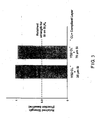
- FIG. 3 shows four-point bending strength of SN282 silicon nitride with the new environmental barrier coating (EBC) bond coat architecture, shown as a fraction of the strength retained compared to the baseline SN282 material (without an EBC). Two different variations of the new bond coat architecture are shown. The range of baseline strength for uncoated SN282 is indicated by the shading. The dashed line shows the typical fraction of retained strength using the prior art EBC architecture, where silicon was applied directly to the silicon nitride substrate. Description of the examples below further demonstrates the advantages of the new EBC architecture.
- EBC environmental barrier coating
- the flexure strength of the coated samples was measured in four-point bending and the average strength was found to be 90% of that of uncoated silicon nitride bars.
- Air plasma spray was used to deposit 125 microns of silicon on a silicon nitride substrate.
- the flexure strength of coated bars was measured in four-point bending and the average strength was found to be approximately 50% of that of uncoated silicon nitride bars.
Landscapes
- Chemical & Material Sciences (AREA)
- Engineering & Computer Science (AREA)
- Inorganic Chemistry (AREA)
- Materials Engineering (AREA)
- Organic Chemistry (AREA)
- Ceramic Engineering (AREA)
- Metallurgy (AREA)
- Mechanical Engineering (AREA)
- Chemical Kinetics & Catalysis (AREA)
- Structural Engineering (AREA)
- Laminated Bodies (AREA)
- Turbine Rotor Nozzle Sealing (AREA)
- Other Surface Treatments For Metallic Materials (AREA)
Abstract
Description
- The present invention is drawn to a bond coat system to be applied to a silicon containing substrate.
- Silicon-based monolithic ceramics such as, silicon carbide and silicon nitride, and composites such as, silicon carbide fiber reinforced silicon carbide matrix are attractive materials for use in gas turbine engine hot sections due to their high temperature mechanical and physical properties as well as lower density than metals. However, these materials exhibit accelerated oxidation and recession in high temperature, aqueous environments such as, for example, the combustor and turbine sections of gas turbine engines. In order to reduce the rate of oxidation and recession at high temperatures in substrates used as ceramic components in such environments, significant effort has been given to providing barrier layers for the protection of the silicon based substrates so as to increase the service life of such components.
- One variant of a protected coated ceramic article that constitutes prior art is shown in Figure 1a. A
composite article 10 comprises a silicon basedsubstrate 12, a bond coat orlayer 14 which comprises a dense continuous layer of silicon metal, and an environmental barrier coating comprising abarrier layer 16 which comprises either an alkaline earth aluminosilicate based on barium and/or strontium; or yttrium silicate. Anotherrefractory top layer 18, such as, for example, aluminum oxide; or zirconium oxide; or yttrium oxide; or combinations thereof may be used on top of thebarrier layer 16. Another embodiment of the prior art is shown in Figure 1b whereintermediate layers substrate 12. However, it has now been found that when the coatings depicted in the prior art are applied to some silicon-containing substrates such as silicon nitride, their mechanical properties suffer as demonstrated by a reduction in the flexure or tensile strength. It is believed that a loss in mechanical properties results from mechanical incompatibilities between thebond coat 14 and silicon-containingsubstrate 12. It has been found that a mismatch in elastic modulus and thermal expansion coefficients betweenbond coat 14 and the silicon-containingsubstrate 12 results in thermal strains in thebond coat 14 and silicon-containingsubstrate 12 when the coatedsystem 10 is subject to thermal excursions such as cooling from the annealing temperature and/or heating and cooling cycles during gas turbine engine operation. It has also been found that the stored elastic strain energy required for crack propagation would be high in such systems. It is further found that failure in coating systems and brittle ceramics can occur due to high strains and stresses and/or high elastic stored energy in the system. Due to the brittle nature of silicon bond coat and silicon-containing substrate, the thermal strains and the resulting thermal stresses can lead to cracking in the bond layer or substrate or cause delamination of the interface between the bond coat and substrate. High thermal stresses may also lead to local stress concentrations and activate small defects or flaws in the bond coat or silicon-containing substrate leading to a failure well below the typical substrate strength. - Based upon the foregoing, it is clear that the need remains for an improved bond coat system for silicon based ceramic substrates that does not adversely affect the mechanical behavior of the substrate such as reduction in the flexure or tensile strength. It is therefore the primary object of the present invention to provide such a coating system architecture.
- Accordingly, it is a principal object of the present invention to provide a bond coat system which does not adversely affect the mechanical properties of silicon based substrates such as silicon nitride. The bond coat system of the invention incorporates the advantages offered by a silicon metal containing bond coat and barrier coating applied thereto while at the same time overcoming the disadvantages noted above.
- The foregoing object is achieved by the present invention wherein a compliant layer preferably having an elastic modulus of between 30 and 130 GPa is provided between a silicon based substrate and an oxygen gettering layer. In the present invention, reduction in substrate strength is mitigated by making the coating system more flaw tolerant by supplying a compliant layer between the oxygen gettering layer and the substrate. The coating system thus retains the advantages of the prior art systems without debiting the strength of the substrate. The mitigation of the strength debit is brought about by the coating design of the present invention, which comprises a compliant layer, oxygen gettering layer, and additional barrier layer(s), which drives down the residual tensile stresses in the layers adjacent to the substrate and/or reduces the stored elastic strain energy of the coated system. Further, the compliant layer acts to buffer the stress concentration in the substrate thereby helping to retain the strength of the substrate. The bond coat system of the present invention is a significant improvement over prior art systems known to date.
- Further features of the invention will appear in the following detailed description and accompanying drawings.
-
- Figures 1a and 1b are schematic illustrations of composite articles in accordance with the prior art;
- Figure 2 is a schematic illustration of the composite article in accordance with one embodiment of the present invention; and
- Figure 3 is a graph showing the advantages of the present invention with respect to retained strength of the coated article.
- With reference to Figure 2, the
composite article 100 of the present invention is illustrated and comprises a silicon basedsubstrate 120, an oxygen getteringlayer 140 and acompliant layer 30 between the silicon based substrate and the silicon metal containing oxygen gettering layer. It should be noted here that the bond coat materials in the prior art are mostly oxygen gettering agents such as Silicon (Si) and refractory metal silicides and combinations thereof. While a Silicon containing oxygen getteringlayer 140, is a preferred embodiment of this invention, alternatively,layer 140 could also be high temperature metallic alloys that are alumina or chromia formers as known in the art. - In accordance with preferred embodiments of the present invention, the
compliant layer 30, is selected from the group consisting of alkaline earth alumino silicates, yttrium monosilicate, yttrium disilicate, rare earth mono and disilicates, hafnium silicate, zirconium silicate; oxides of hafnium, zirconium, yttrium, rare earth metals, niobium, titanium, tantalum, silicon, aluminum; silicon nitride; silicon carbide; silicon oxynitrides; silicon oxy carbides; silicon oxycarbonitrides; silicon refractory metal oxides; alumina forming refractory metal alloys; chromia forming refractory metal alloys, and mixtures thereof. It is preferred that the composition of the compliant layer be selected from the group consisting of yttrium oxide, hafnium oxide, rare earth metal oxides, yttrium monosilicate, yttrium disilicate, rare earth mono and disilicates, hafnium silicate, and mixtures thereof. The preferred elastic modulus of the compliant layer is 30-130 GPa. The porosity of the compliant layer must be controlled in order to ensure the desired behavior characteristics noted above. It is preferred that the compliant layer have a porosity of about 2 to 50%, and more preferably about 5 to 25%. Porosity refers to the fraction of voids in thecompliant layer 30. The thickness of the compliant layer is preferred to be between 20 and 250 microns and more preferably between 40 and 125 microns. The ratio of thickness of the compliant layer to the oxygen gettering layer is preferred to be between 0.1:1 and 10:1.
Thecompliant layer 30 may comprise a plurality of layers having the composition of the materials set forth above. Thecompliant layer 30 and getteringlayer 140 may be repeated one or more times in the environmental barrier coating system if desired. - The silicon based
substrate 120 includes materials selected from the group consisting of monolithic silicon nitride, monolithic silicon carbide, silicon nitride containing composites, silicon carbide containing composites, silicon oxynitrides, silicon oxycarbides, silicon carbonitrides, molybdenum alloys containing silicon, niobium alloys containing silicon. - The article of the present invention includes further
environmental barrier layers - The layers described above may be applied by any processing methods known in prior art which include, thermal spraying, chemical vapor deposition, physical vapor deposition, electrophoretic deposition, electrostatic deposition, preceramic polymer pyrolysis, sol-gel, slurry coating, dipping, air-brushing, sputtering, slurry painting or any combination thereof. In order to obtain the desired porosity in the compliant layer, sacrificial pore formers can be used to introduce the porosity into the compliant layer. Sacrificial pore formers are well known in the art and include materials such as polyesters, polystyrene, etc.
- By employing the bond coat system of the present invention wherein a compliant layer with elastic modulus between 30 and 130 GPa is used in conjunction with an oxygen gettering layer, crack initiation and/or propagation from coating to the substrate or vice-versa is mitigated. This results in the strength retention of coated substrates close to that of baseline substrates, which is critical for structural applications. Figure 3 shows four-point bending strength of SN282 silicon nitride with the new environmental barrier coating (EBC) bond coat architecture, shown as a fraction of the strength retained compared to the baseline SN282 material (without an EBC). Two different variations of the new bond coat architecture are shown. The range of baseline strength for uncoated SN282 is indicated by the shading. The dashed line shows the typical fraction of retained strength using the prior art EBC architecture, where silicon was applied directly to the silicon nitride substrate. Description of the examples below further demonstrates the advantages of the new EBC architecture.
- 26.67 gm of yttrium disilicate (Y2Si2O7) was added to 10 ml of deionized water with 2.5% Darvan by weight (2.5 gm Darvan in 100 ml water). The slurry was ball milled for 30 minutes. Six silicon nitride bars were dipped in the slurry and dried. The coated bars were subsequently fired at 1350 °C for 5 hours. The dip process was repeated another time and the bars were refired at 1350 °C for 5 hours. Subsequently, the samples were introduced in a CVD reactor and coated with 35 and 70 microns of silicon. The reactor was maintained at 850-900°C and the deposition of silicon was carried out as per the following reaction:
SiH2Cl2(g)+H2(g)→Si(s)2HCl (g) + H2 (g)
- The flexure strength of the coated samples was measured in four-point bending and the average strength was found to be comparable to that of the uncoated silicon nitride samples (Figure 3). As can be seen from Figure 3 the high strength of uncoated silicon nitride is maintained even after it is coated.
- 31.33 gm of yttrium monosilicate (Y2SiO5) was added to 10 ml of water with 2.5% Darvan by weight (2.5 gm Darvan in 100 ml water). The slurry was ball milled for 30 minutes. Six silicon nitride bars were dipped in the slurry and dried. The coated bars were subsequently fired at 1350 °C for 5 hours. The dip process was repeated another time and the bars were refired at 1350 °C for 5 hours. Subsequently, the samples were introduced in a CVD reactor and coated with 20 microns of silicon. The reactor was maintained at 850-900°C and the deposition of silicon was carried out as per the following reaction:
SiH2Cl2 (g) +H2 (g)→ Si (s) +2HCl (g) + H2 (g)
- The flexure strength of the coated samples was measured in four-point bending and the average strength was found to be 90% of that of uncoated silicon nitride bars.
- Air plasma spray was used to deposit 125 microns of silicon on a silicon nitride substrate. The flexure strength of coated bars was measured in four-point bending and the average strength was found to be approximately 50% of that of uncoated silicon nitride bars.
- It is to be understood that the invention is not limited to the illustrations described and shown herein, which are deemed to be merely illustrative of the best modes of carrying out the invention, and which are susceptible of modification of form, size, arrangement of parts and details of operation. The invention rather is intended to encompass all such modifications which are within scope as defined by the claims.
Claims (17)
- An article (100) comprising:a silicon based substrate (120);an oxygen gettering layer (140);a compliant layer (30) between the silicon based substrate (120) and the oxygen gettering layer (140), wherein the compliant layer (30) has an elastic modulus of between 30 and 130 GPa; andan environmental barrier coating (EBC) (160,180) on the oxygen gettering layer (140).
- An article according to claim 1, wherein the compliant layer (30) is selected from the group consisting of alkaline earth alumino silicates, yttrium monosilicate, yttrium disilicate, rare earth mono and disilicates, hafnium silicate, zirconium silicate; oxides of hafnium, zirconium, yttrium, rare earth metals, niobium, titanium, tantalum, silicon, aluminum; silicon nitride; silicon carbide; silicon oxynitrides; silicon oxy carbides; silicon oxycarbonitrides; silicon refractory metal oxides; alumina forming refractory metal alloys; chromia forming refractory metal alloys; and mixtures thereof.
- An article according to claim 2, wherein the compliant layer (30) has a porosity of about 2 to 50%.
- An article according to claim 3, wherein the compliant layer (30) has a porosity of about 5 to 25%.
- An article according to claim 2, 3 or 4, wherein the compliant layer (30) has a thickness of between 20 and 250 microns.
- An article according to claim 5, wherein the compliant layer (30) has a thickness of between 40 and 125 microns.
- An article according to any of claims 2 to 6, wherein the compliant layer (30) is selected from the group consisting of yttrium oxide, hafnium oxide, rare earth metal oxides, yttrium monosilicate, yttrium disilicate, rare earth mono and disilicates, hafnium silicate, and mixtures thereof.
- An article according to any preceding claim, wherein the compliant layer (30) and the oxygen gettering layer (140) have a ratio of thickness of complaint layer (30) to gettering layer (140) of about 0.1:1 and 10:1.
- An article according to any preceding claim, wherein the silicon based substrate (120) is selected from the group consisting of monolithic silicon nitride, monolithic silicon carbide, silicon nitride containing composites, silicon carbide containing composites, silicon oxynitrides, silicon carbonitrides, silicon oxycarbides; molybdenum alloys containing silicon, niobium alloys containing silicon.
- An article according to any preceding claim, wherein the EBC (160,180) comprises of at least one layer selected from the group consisting of mullite, alkaline earth aluminosilicates, barium strontium aluminosilicate, yttrium silicates, rare earth silicates, hafnium oxide, zirconium oxide, titanium oxide, silicon oxide, yttrium oxide, rare earth metal oxides, tantalum oxide, niobium oxide, aluminum oxide, and mixtures thereof.
- An article according to claim 10, wherein the EBC comprises a plurality of layers (160,180) .
- An article according to any preceding claim, wherein the oxygen gettering layer (140) is selected from the group consisting of silicon metal, silicon metal alloys, intermetallic silicides, chromia forming metallic alloys, alumina forming metallic alloys, and mixtures thereof.
- The article according to any preceding claim, wherein the compliant layer (30) and oxygen gettering layer (140) are repeated at least once.
- The article according to any preceding claim, wherein the EBC coating (160,180) is on substantially all of the oxygen gettering layer (140).
- An article (100) comprising a composite comprising a coated silicon based substrate (120), with an oxygen gettering layer (140) and a compliant layer (30) therebetween that retains about 70% and more preferably 90% and more of its original substrate strength.
- A method of making the article according to any preceding claim, wherein at least one of the compliant layer (30), oxygen gettering layer (140) and the EBC (160,180) is deposited using thermal spraying, chemical vapor deposition, physical vapor deposition, electrophoretic deposition, electrostatic deposition, preceramic polymer pyrolysis, sol-gel, slurry coating, dipping, air-brushing, sputtering, slurry painting or any combination thereof.
- A method of making the article according to any of claims 1 to 5, wherein at least one sacrificial pore former is used to control the porosity and thereby modulus of the compliant layer (30).
Applications Claiming Priority (1)
| Application Number | Priority Date | Filing Date | Title |
|---|---|---|---|
| US11/135,857 US7374818B2 (en) | 2005-05-23 | 2005-05-23 | Coating system for silicon based substrates |
Publications (2)
| Publication Number | Publication Date |
|---|---|
| EP1726681A1 true EP1726681A1 (en) | 2006-11-29 |
| EP1726681B1 EP1726681B1 (en) | 2010-05-05 |
Family
ID=36782579
Family Applications (1)
| Application Number | Title | Priority Date | Filing Date |
|---|---|---|---|
| EP06251493A Expired - Lifetime EP1726681B1 (en) | 2005-05-23 | 2006-03-21 | Coating system for silicon based substrates |
Country Status (5)
| Country | Link |
|---|---|
| US (1) | US7374818B2 (en) |
| EP (1) | EP1726681B1 (en) |
| JP (1) | JP2006327923A (en) |
| CN (1) | CN100415693C (en) |
| DE (1) | DE602006014058D1 (en) |
Cited By (2)
| Publication number | Priority date | Publication date | Assignee | Title |
|---|---|---|---|---|
| WO2008049392A3 (en) * | 2006-10-27 | 2009-10-15 | Mtu Aero Engines Gmbh | Vapour-deposited coating and thermally stressable component having such a coating, and also a process and apparatus for producing such a coating |
| WO2015108743A1 (en) * | 2014-01-14 | 2015-07-23 | United Technologies Corporation | Silicon oxycarbide-based environmental barrier coating |
Families Citing this family (50)
| Publication number | Priority date | Publication date | Assignee | Title |
|---|---|---|---|---|
| US9177828B2 (en) | 2011-02-10 | 2015-11-03 | Micron Technology, Inc. | External gettering method and device |
| WO2007098152A2 (en) * | 2006-02-20 | 2007-08-30 | Lee Kang N | Article including enviromental barrier coating system |
| US20090184280A1 (en) * | 2008-01-18 | 2009-07-23 | Rolls-Royce Corp. | Low Thermal Conductivity, CMAS-Resistant Thermal Barrier Coatings |
| US20090186237A1 (en) * | 2008-01-18 | 2009-07-23 | Rolls-Royce Corp. | CMAS-Resistant Thermal Barrier Coatings |
| US20090274850A1 (en) * | 2008-05-01 | 2009-11-05 | United Technologies Corporation | Low cost non-line-of -sight protective coatings |
| US20090324930A1 (en) * | 2008-06-25 | 2009-12-31 | United Technologies Corporation | Protective coatings for silicon based substrates with improved adhesion |
| EP2344590B1 (en) * | 2008-09-30 | 2016-11-30 | Rolls-Royce Corporation | Coating including a rare earth silicate-based layer including a second phase |
| US8124252B2 (en) * | 2008-11-25 | 2012-02-28 | Rolls-Royce Corporation | Abradable layer including a rare earth silicate |
| US8470460B2 (en) * | 2008-11-25 | 2013-06-25 | Rolls-Royce Corporation | Multilayer thermal barrier coatings |
| US8658255B2 (en) * | 2008-12-19 | 2014-02-25 | General Electric Company | Methods for making environmental barrier coatings and ceramic components having CMAS mitigation capability |
| US8119247B2 (en) * | 2008-12-19 | 2012-02-21 | General Electric Company | Environmental barrier coatings providing CMAS mitigation capability for ceramic substrate components |
| US8658291B2 (en) * | 2008-12-19 | 2014-02-25 | General Electric Company | CMAS mitigation compositions, environmental barrier coatings comprising the same, and ceramic components comprising the same |
| US8343589B2 (en) * | 2008-12-19 | 2013-01-01 | General Electric Company | Methods for making environmental barrier coatings and ceramic components having CMAS mitigation capability |
| US8273470B2 (en) * | 2008-12-19 | 2012-09-25 | General Electric Company | Environmental barrier coatings providing CMAS mitigation capability for ceramic substrate components |
| US8039113B2 (en) * | 2008-12-19 | 2011-10-18 | General Electric Company | Environmental barrier coatings providing CMAS mitigation capability for ceramic substrate components |
| US20100154422A1 (en) * | 2008-12-19 | 2010-06-24 | Glen Harold Kirby | Cmas mitigation compositions, environmental barrier coatings comprising the same, and ceramic components comprising the same |
| US8999457B2 (en) * | 2009-07-31 | 2015-04-07 | General Electric Company | Methods for making environmental barrier coatings using sintering aids |
| US9005717B2 (en) * | 2009-07-31 | 2015-04-14 | General Electric Company | Methods for making environmental barrier coatings using sintering aids |
| US9005716B2 (en) * | 2009-07-31 | 2015-04-14 | General Electric Company | Method for making solvent based environmental barrier coatings using sintering aids |
| US8673400B2 (en) * | 2009-07-31 | 2014-03-18 | General Electric Company | Methods of improving surface roughness of an environmental barrier coating and components comprising environmental barrier coatings having improved surface roughness |
| US9062564B2 (en) * | 2009-07-31 | 2015-06-23 | General Electric Company | Solvent based slurry compositions for making environmental barrier coatings and environmental barrier coatings comprising the same |
| US20110027517A1 (en) * | 2009-07-31 | 2011-02-03 | Glen Harold Kirby | Methods of improving surface roughness of an environmental barrier coating and components comprising environmental barrier coatings having improved surface roughness |
| US9023435B2 (en) * | 2009-07-31 | 2015-05-05 | General Electric Company | Methods for making water based environmental barrier coatings using sintering aids |
| US8501840B2 (en) * | 2009-07-31 | 2013-08-06 | General Electric Company | Water based slurry compositions for making environmental barrier coatings and environmental barrier coatings comprising the same |
| US20110027559A1 (en) | 2009-07-31 | 2011-02-03 | Glen Harold Kirby | Water based environmental barrier coatings for high temperature ceramic components |
| US20110027557A1 (en) * | 2009-07-31 | 2011-02-03 | Glen Harold Kirby | Solvent based environmental barrier coatings for high temperature ceramic components |
| US20110033630A1 (en) * | 2009-08-05 | 2011-02-10 | Rolls-Royce Corporation | Techniques for depositing coating on ceramic substrate |
| US20110206937A1 (en) * | 2010-02-25 | 2011-08-25 | Schmidt Wayde R | Composite article having a ceramic nanocomposite layer |
| US8470457B2 (en) * | 2010-03-29 | 2013-06-25 | United Technologies Corporation | Composite article having a solid solution protective layer |
| EP2596068B1 (en) | 2010-07-23 | 2015-09-02 | Rolls-Royce Corporation | Thermal barrier coatings including c mas-resistant thermal barrier coating layers |
| WO2012027442A1 (en) | 2010-08-27 | 2012-03-01 | Rolls-Royce Corporation | Rare earth silicate environmental barrier coatings |
| CN102398049B (en) * | 2010-09-09 | 2015-11-25 | 三菱综合材料株式会社 | The resistance to surface-coated cutting tool collapsing cutter |
| US8475945B2 (en) * | 2011-06-23 | 2013-07-02 | United Technologies Corporation | Composite article including silicon oxycarbide layer |
| US10094236B2 (en) * | 2013-03-15 | 2018-10-09 | General Electric Company | Recession resistant ceramic matrix composites and environmental barrier coatings |
| CN103483009A (en) * | 2013-08-30 | 2014-01-01 | 西北工业大学 | Preparation method of multilayer environmental barrier coating (EBC) structure with anti-cracking expansion ability |
| US9938839B2 (en) | 2014-03-14 | 2018-04-10 | General Electric Company | Articles having reduced expansion and hermetic environmental barrier coatings and methods for their manufacture |
| US10329205B2 (en) | 2014-11-24 | 2019-06-25 | Rolls-Royce Corporation | Bond layer for silicon-containing substrates |
| EP3141631B1 (en) * | 2015-09-10 | 2018-03-14 | Rolls-Royce High Temperature Composites Inc | Applying silicon metal-containing bond layer to ceramic or ceramic matrix composite substrates |
| JP6067166B1 (en) * | 2016-05-13 | 2017-01-25 | 三菱日立パワーシステムズ株式会社 | COATING STRUCTURE, TURBINE COMPONENT HAVING THE SAME, AND METHOD FOR PRODUCING COATING STRUCTURE |
| GB201616239D0 (en) * | 2016-09-23 | 2016-11-09 | Intelligent Power Generation Limited | Axial Turbine |
| CN107032831B (en) * | 2017-03-29 | 2018-02-23 | 北京航空航天大学 | A kind of Rare Earth T/EBC ceramic bases combinational environment barrier coating and preparation method thereof |
| CN110475944B (en) * | 2017-04-25 | 2022-07-29 | 通用电气公司 | Gas turbine component and method of assembling same |
| US20190017177A1 (en) | 2017-07-17 | 2019-01-17 | Rolls-Royce Corporation | Thermal barrier coatings for components in high-temperature mechanical systems |
| US11655543B2 (en) | 2017-08-08 | 2023-05-23 | Rolls-Royce Corporation | CMAS-resistant barrier coatings |
| US10851656B2 (en) | 2017-09-27 | 2020-12-01 | Rolls-Royce Corporation | Multilayer environmental barrier coating |
| CN109320301B (en) * | 2018-09-29 | 2021-09-14 | 中国航空工业集团公司基础技术研究院 | SiC/SiC composite material wide-temperature-range thermal protection coating and preparation method thereof |
| US11034842B2 (en) * | 2018-12-14 | 2021-06-15 | General Electric Company | Coating for improved surface finish |
| CN110026249B (en) * | 2019-04-17 | 2021-05-25 | 天津大学 | Atomic-scale micro-nano catalytic capsule for degrading VOCs at normal temperature " |
| US11866380B2 (en) * | 2019-08-09 | 2024-01-09 | Rtx Corporation | Method for fabricating an environmental barrier coating on a ceramic matrix composite |
| CN116514055B (en) * | 2023-06-27 | 2023-11-28 | 深圳市汉嵙新材料技术有限公司 | Composite hydrogen storage membrane material, preparation method thereof and hydrogen storage tank |
Citations (13)
| Publication number | Priority date | Publication date | Assignee | Title |
|---|---|---|---|---|
| EP0310043A2 (en) * | 1987-10-01 | 1989-04-05 | Gte Laboratories Incorporated | Oxidation resistant, high temperature thermal cycling resistant coating on silicon-based substrates and process for the production thereof |
| EP1044944A1 (en) * | 1999-04-15 | 2000-10-18 | United Technologies Corporation | Silicon based substrate with yttrium silicate environmental/thermal barrier layer and method for preparing an article therefrom |
| EP1044943A1 (en) * | 1999-04-15 | 2000-10-18 | United Technologies Corporation | Silicon based substrate with environmental/thermal barrier layer |
| EP1044947A2 (en) * | 1999-04-15 | 2000-10-18 | United Technologies Corporation | Method for applying a barrier layer to a silicon based substrate and an article prepared in accordance with the method |
| EP1044946A2 (en) * | 1999-04-15 | 2000-10-18 | United Technologies Corporation | Silicon based substrate with calcium aluminosilicate environmental/thermal barrier layer |
| US6299988B1 (en) * | 1998-04-27 | 2001-10-09 | General Electric Company | Ceramic with preferential oxygen reactive layer |
| US6485848B1 (en) * | 1998-04-27 | 2002-11-26 | General Electric Company | Coated article and method of making |
| US6517960B1 (en) * | 1999-04-26 | 2003-02-11 | General Electric Company | Ceramic with zircon coating |
| US20030138641A1 (en) * | 2001-12-28 | 2003-07-24 | Kyocera Corporation | Corrosion-resistant ceramics |
| EP1479656A2 (en) * | 2003-05-22 | 2004-11-24 | United Technologies Corporation | Bond coat for silicon based substrates |
| EP1479658A2 (en) * | 2003-05-22 | 2004-11-24 | United Technologies Corporation | Bond layer for silicon based substrates |
| EP1479657A1 (en) * | 2003-05-22 | 2004-11-24 | United Technologies Corporation | Environmental barrier coating for silicon based substrates |
| EP1479659A2 (en) * | 2003-05-22 | 2004-11-24 | United Technologies Corporation | Bond coating for silicon based substrates such as silicon nitride |
Family Cites Families (3)
| Publication number | Priority date | Publication date | Assignee | Title |
|---|---|---|---|---|
| US4639388A (en) * | 1985-02-12 | 1987-01-27 | Chromalloy American Corporation | Ceramic-metal composites |
| CN1112337C (en) * | 1999-05-28 | 2003-06-25 | 清华大学 | Preparation of silicon nitride-based composite material with superhigh tenacity |
| US6759151B1 (en) * | 2002-05-22 | 2004-07-06 | The United States Of America As Represented By The Administrator Of The National Aeronautics And Space Administration | Multilayer article characterized by low coefficient of thermal expansion outer layer |
-
2005
- 2005-05-23 US US11/135,857 patent/US7374818B2/en not_active Expired - Lifetime
-
2006
- 2006-03-20 JP JP2006075908A patent/JP2006327923A/en active Pending
- 2006-03-21 EP EP06251493A patent/EP1726681B1/en not_active Expired - Lifetime
- 2006-03-21 DE DE602006014058T patent/DE602006014058D1/en not_active Expired - Lifetime
- 2006-03-22 CN CNB2006100682523A patent/CN100415693C/en not_active Expired - Fee Related
Patent Citations (13)
| Publication number | Priority date | Publication date | Assignee | Title |
|---|---|---|---|---|
| EP0310043A2 (en) * | 1987-10-01 | 1989-04-05 | Gte Laboratories Incorporated | Oxidation resistant, high temperature thermal cycling resistant coating on silicon-based substrates and process for the production thereof |
| US6485848B1 (en) * | 1998-04-27 | 2002-11-26 | General Electric Company | Coated article and method of making |
| US6299988B1 (en) * | 1998-04-27 | 2001-10-09 | General Electric Company | Ceramic with preferential oxygen reactive layer |
| EP1044947A2 (en) * | 1999-04-15 | 2000-10-18 | United Technologies Corporation | Method for applying a barrier layer to a silicon based substrate and an article prepared in accordance with the method |
| EP1044946A2 (en) * | 1999-04-15 | 2000-10-18 | United Technologies Corporation | Silicon based substrate with calcium aluminosilicate environmental/thermal barrier layer |
| EP1044943A1 (en) * | 1999-04-15 | 2000-10-18 | United Technologies Corporation | Silicon based substrate with environmental/thermal barrier layer |
| EP1044944A1 (en) * | 1999-04-15 | 2000-10-18 | United Technologies Corporation | Silicon based substrate with yttrium silicate environmental/thermal barrier layer and method for preparing an article therefrom |
| US6517960B1 (en) * | 1999-04-26 | 2003-02-11 | General Electric Company | Ceramic with zircon coating |
| US20030138641A1 (en) * | 2001-12-28 | 2003-07-24 | Kyocera Corporation | Corrosion-resistant ceramics |
| EP1479656A2 (en) * | 2003-05-22 | 2004-11-24 | United Technologies Corporation | Bond coat for silicon based substrates |
| EP1479658A2 (en) * | 2003-05-22 | 2004-11-24 | United Technologies Corporation | Bond layer for silicon based substrates |
| EP1479657A1 (en) * | 2003-05-22 | 2004-11-24 | United Technologies Corporation | Environmental barrier coating for silicon based substrates |
| EP1479659A2 (en) * | 2003-05-22 | 2004-11-24 | United Technologies Corporation | Bond coating for silicon based substrates such as silicon nitride |
Cited By (3)
| Publication number | Priority date | Publication date | Assignee | Title |
|---|---|---|---|---|
| WO2008049392A3 (en) * | 2006-10-27 | 2009-10-15 | Mtu Aero Engines Gmbh | Vapour-deposited coating and thermally stressable component having such a coating, and also a process and apparatus for producing such a coating |
| WO2015108743A1 (en) * | 2014-01-14 | 2015-07-23 | United Technologies Corporation | Silicon oxycarbide-based environmental barrier coating |
| US12091756B2 (en) | 2014-01-14 | 2024-09-17 | Rtx Corporation | Silicon oxycarbide-based environmental barrier coating |
Also Published As
| Publication number | Publication date |
|---|---|
| EP1726681B1 (en) | 2010-05-05 |
| JP2006327923A (en) | 2006-12-07 |
| CN100415693C (en) | 2008-09-03 |
| DE602006014058D1 (en) | 2010-06-17 |
| CN1868973A (en) | 2006-11-29 |
| US7374818B2 (en) | 2008-05-20 |
| US20070014996A1 (en) | 2007-01-18 |
Similar Documents
| Publication | Publication Date | Title |
|---|---|---|
| US7374818B2 (en) | Coating system for silicon based substrates | |
| US20090324930A1 (en) | Protective coatings for silicon based substrates with improved adhesion | |
| CN101024324B (en) | Environment barrier coating for a component and method for fabricating the same | |
| EP1044946B1 (en) | Silicon based substrate with calcium aluminosilicate environmental/thermal barrier layer | |
| CN101528641B (en) | Corrosion-resistant composite parts with a silicon-containing ceramic matrix | |
| US6387456B1 (en) | Silicon based substrate with environmental/thermal barrier layer | |
| JP3866002B2 (en) | Article having silicon-containing substrate and yttrium-containing barrier layer and method for producing the same | |
| RU2436868C2 (en) | Protected from corrosion component of composite material with ceramic matrix containing silicon | |
| EP1764351A2 (en) | Silicon based substrate with hafnium silicate containing barrier layer | |
| US10851656B2 (en) | Multilayer environmental barrier coating | |
| JP2007197307A5 (en) | ||
| JP2007247055A (en) | Coating method and coating article | |
| JP4109651B2 (en) | Article comprising a silicon substrate, a bond layer and an additional layer provided on the bond layer | |
| EP1479658B1 (en) | Gas turbine engine combustor or turbine section | |
| EP1626040B1 (en) | Coating process to enable electrophoretic deposition | |
| JP4178239B2 (en) | High adhesion oxide film and method for producing the same | |
| Lewinsohn et al. | Progress in EBC Development for Silicon‐Based, Non‐Oxide Ceramics |
Legal Events
| Date | Code | Title | Description |
|---|---|---|---|
| PUAI | Public reference made under article 153(3) epc to a published international application that has entered the european phase |
Free format text: ORIGINAL CODE: 0009012 |
|
| AK | Designated contracting states |
Kind code of ref document: A1 Designated state(s): AT BE BG CH CY CZ DE DK EE ES FI FR GB GR HU IE IS IT LI LT LU LV MC NL PL PT RO SE SI SK TR |
|
| AX | Request for extension of the european patent |
Extension state: AL BA HR MK YU |
|
| 17P | Request for examination filed |
Effective date: 20070110 |
|
| 17Q | First examination report despatched |
Effective date: 20070205 |
|
| AKX | Designation fees paid |
Designated state(s): DE FR GB |
|
| GRAP | Despatch of communication of intention to grant a patent |
Free format text: ORIGINAL CODE: EPIDOSNIGR1 |
|
| GRAS | Grant fee paid |
Free format text: ORIGINAL CODE: EPIDOSNIGR3 |
|
| GRAA | (expected) grant |
Free format text: ORIGINAL CODE: 0009210 |
|
| AK | Designated contracting states |
Kind code of ref document: B1 Designated state(s): DE FR GB |
|
| REG | Reference to a national code |
Ref country code: GB Ref legal event code: FG4D |
|
| REF | Corresponds to: |
Ref document number: 602006014058 Country of ref document: DE Date of ref document: 20100617 Kind code of ref document: P |
|
| PLBE | No opposition filed within time limit |
Free format text: ORIGINAL CODE: 0009261 |
|
| STAA | Information on the status of an ep patent application or granted ep patent |
Free format text: STATUS: NO OPPOSITION FILED WITHIN TIME LIMIT |
|
| 26N | No opposition filed |
Effective date: 20110208 |
|
| REG | Reference to a national code |
Ref country code: DE Ref legal event code: R097 Ref document number: 602006014058 Country of ref document: DE Effective date: 20110207 |
|
| PGFP | Annual fee paid to national office [announced via postgrant information from national office to epo] |
Ref country code: FR Payment date: 20110317 Year of fee payment: 6 |
|
| REG | Reference to a national code |
Ref country code: FR Ref legal event code: ST Effective date: 20121130 |
|
| PG25 | Lapsed in a contracting state [announced via postgrant information from national office to epo] |
Ref country code: FR Free format text: LAPSE BECAUSE OF NON-PAYMENT OF DUE FEES Effective date: 20120402 |
|
| REG | Reference to a national code |
Ref country code: DE Ref legal event code: R082 Ref document number: 602006014058 Country of ref document: DE Representative=s name: SCHMITT-NILSON SCHRAUD WAIBEL WOHLFROM PATENTA, DE |
|
| REG | Reference to a national code |
Ref country code: DE Ref legal event code: R082 Ref document number: 602006014058 Country of ref document: DE Representative=s name: SCHMITT-NILSON SCHRAUD WAIBEL WOHLFROM PATENTA, DE Ref country code: DE Ref legal event code: R081 Ref document number: 602006014058 Country of ref document: DE Owner name: UNITED TECHNOLOGIES CORP. (N.D.GES.D. STAATES , US Free format text: FORMER OWNER: UNITED TECHNOLOGIES CORP., HARTFORD, CONN., US |
|
| REG | Reference to a national code |
Ref country code: DE Ref legal event code: R081 Ref document number: 602006014058 Country of ref document: DE Owner name: RAYTHEON TECHNOLOGIES CORPORATION (N.D.GES.D.S, US Free format text: FORMER OWNER: UNITED TECHNOLOGIES CORP. (N.D.GES.D. STAATES DELAWARE), FARMINGTON, CONN., US |
|
| PGFP | Annual fee paid to national office [announced via postgrant information from national office to epo] |
Ref country code: GB Payment date: 20230222 Year of fee payment: 18 Ref country code: DE Payment date: 20230221 Year of fee payment: 18 |
|
| P01 | Opt-out of the competence of the unified patent court (upc) registered |
Effective date: 20230519 |
|
| REG | Reference to a national code |
Ref country code: DE Ref legal event code: R119 Ref document number: 602006014058 Country of ref document: DE |
|
| GBPC | Gb: european patent ceased through non-payment of renewal fee |
Effective date: 20240321 |
|
| PG25 | Lapsed in a contracting state [announced via postgrant information from national office to epo] |
Ref country code: DE Free format text: LAPSE BECAUSE OF NON-PAYMENT OF DUE FEES Effective date: 20241001 |
|
| PG25 | Lapsed in a contracting state [announced via postgrant information from national office to epo] |
Ref country code: GB Free format text: LAPSE BECAUSE OF NON-PAYMENT OF DUE FEES Effective date: 20240321 |
|
| PG25 | Lapsed in a contracting state [announced via postgrant information from national office to epo] |
Ref country code: GB Free format text: LAPSE BECAUSE OF NON-PAYMENT OF DUE FEES Effective date: 20240321 Ref country code: DE Free format text: LAPSE BECAUSE OF NON-PAYMENT OF DUE FEES Effective date: 20241001 |