EP1726520A2 - Shift operation device for bicycle - Google Patents
Shift operation device for bicycle Download PDFInfo
- Publication number
- EP1726520A2 EP1726520A2 EP06010556A EP06010556A EP1726520A2 EP 1726520 A2 EP1726520 A2 EP 1726520A2 EP 06010556 A EP06010556 A EP 06010556A EP 06010556 A EP06010556 A EP 06010556A EP 1726520 A2 EP1726520 A2 EP 1726520A2
- Authority
- EP
- European Patent Office
- Prior art keywords
- releasing
- positioning
- cable
- pawl
- shift operation
- Prior art date
- Legal status (The legal status is an assumption and is not a legal conclusion. Google has not performed a legal analysis and makes no representation as to the accuracy of the status listed.)
- Granted
Links
Images


Classifications
-
- B—PERFORMING OPERATIONS; TRANSPORTING
- B62—LAND VEHICLES FOR TRAVELLING OTHERWISE THAN ON RAILS
- B62M—RIDER PROPULSION OF WHEELED VEHICLES OR SLEDGES; POWERED PROPULSION OF SLEDGES OR SINGLE-TRACK CYCLES; TRANSMISSIONS SPECIALLY ADAPTED FOR SUCH VEHICLES
- B62M25/00—Actuators for gearing speed-change mechanisms specially adapted for cycles
- B62M25/02—Actuators for gearing speed-change mechanisms specially adapted for cycles with mechanical transmitting systems, e.g. cables, levers
- B62M25/04—Actuators for gearing speed-change mechanisms specially adapted for cycles with mechanical transmitting systems, e.g. cables, levers hand actuated
-
- B—PERFORMING OPERATIONS; TRANSPORTING
- B62—LAND VEHICLES FOR TRAVELLING OTHERWISE THAN ON RAILS
- B62K—CYCLES; CYCLE FRAMES; CYCLE STEERING DEVICES; RIDER-OPERATED TERMINAL CONTROLS SPECIALLY ADAPTED FOR CYCLES; CYCLE AXLE SUSPENSIONS; CYCLE SIDE-CARS, FORECARS, OR THE LIKE
- B62K23/00—Rider-operated controls specially adapted for cycles, i.e. means for initiating control operations, e.g. levers, grips
- B62K23/02—Rider-operated controls specially adapted for cycles, i.e. means for initiating control operations, e.g. levers, grips hand actuated
- B62K23/06—Levers
-
- Y—GENERAL TAGGING OF NEW TECHNOLOGICAL DEVELOPMENTS; GENERAL TAGGING OF CROSS-SECTIONAL TECHNOLOGIES SPANNING OVER SEVERAL SECTIONS OF THE IPC; TECHNICAL SUBJECTS COVERED BY FORMER USPC CROSS-REFERENCE ART COLLECTIONS [XRACs] AND DIGESTS
- Y10—TECHNICAL SUBJECTS COVERED BY FORMER USPC
- Y10T—TECHNICAL SUBJECTS COVERED BY FORMER US CLASSIFICATION
- Y10T74/00—Machine element or mechanism
- Y10T74/20—Control lever and linkage systems
- Y10T74/20396—Hand operated
- Y10T74/20402—Flexible transmitter [e.g., Bowden cable]
- Y10T74/2042—Flexible transmitter [e.g., Bowden cable] and hand operator
- Y10T74/20438—Single rotatable lever [e.g., for bicycle brake or derailleur]
Definitions
- the present invention relates to a shift operation device, and more particularly to a shift operation device for a bicycle that is mounted to a frame of the bicycle for performing a shift operation for switching among a plurality of shift positions of a shift device connected by a shift cable.
- Some bicycles include a shift device such as an internal shift device or an external shift device.
- a shift operation device connected to the shift device via a shift cable has been used.
- a conventionally known shift operation device is of an operation member type including a winding operation member and a releasing operation member in the form of an operation member that oscillates.
- As the shift operation device of the operation member type a technique for oscillably operating the winding operation member and the releasing operation member in the same direction (for example, see Japanese Patent No. 2730555 ) and a technique for oscillably operating the operation members in different directions (for example, see Japanese Patent No. 3065656 ) are known.
- the winding operation member and the releasing operation member are operated in a direction of being pressed with a thumb to cause a shift cable to be wound or released for shifting.
- the winding operation member is operated in a direction of being pressed with a thumb to cause a shift cable to be pulled in a winding direction on a step-by-step basis for shifting, and the winding operation member is operated in a direction of being pulled with an index finger to cause the shift cable to return to a releasing direction for shifting.
- the operation direction of the winding operation member is the direction of being pressed with the thumb.
- the operation direction of the releasing operation member is the same direction as the winding operation member in the former technique, and a different direction from the winding operation member in the latter technique.
- the operation directions of the winding operation member and the releasing operation member are sometimes desired to be changed in response to rider's preference.
- the operation direction of the operation member is limited to a fixed direction and cannot be suited to the rider's preference.
- An object of the present invention is to provide a shift operation device for a bicycle having an operation member that can suit an operation direction of the operation member to rider's preference.
- a shift operation device for a bicycle includes: a mounting portion mountable to the bicycle; a cable lock body; a position holding and releasing mechanism; and a first operation member.
- the cable lock body is mounted to the mounting portion movably to a cable pulling direction and a cable releasing direction.
- the position holding and releasing mechanism selectively holds the cable lock body in any one of a plurality of holding positions.
- the first operation member is mounted to the mounting portion movably in a first direction and a second direction, and operates the position holding and releasing mechanism in response to the movement in the first direction and the second direction to move the cable lock body in the cable releasing direction, respectively.
- the position holding and releasing mechanism is operated in response to the movement to move the cable lock body in the cable releasing direction.
- the cable lock body can be moved in the cable releasing direction when the first operation member is moved in any of the first direction and the second direction, and thus an operation direction of a cable releasing operation by the first operation member can be suited to rider's preference.
- the position holding and releasing mechanism can shift the holding position of the cable lock body by a plurality of positions in response to the movement of the first operation member in at least any one of the first direction and the second direction.
- shift by the plurality of positions can be collectively performed, and thus a plurality of steps of the shift device can be collectively shifted, thereby achieving a quick shift operation.
- the first operation member has a neutral position, and is moved in the first direction and the second direction from the neutral position.
- the cable releasing operation can be performed by operating the first operation member in any direction from the neutral position.
- the first operation member includes an input member movable in the first direction and the second direction, and a drive member that is moved by the input member to operate the position holding and releasing mechanism.
- the first operation member is constituted by the two members: the input member and the drive member, and thus the drive member can be moved to different positions by the input member moving from the same position, thereby allowing a shift operation to be always performed in the same position. This also contributes to design freedom.
- the first operation member further includes a first one-way clutch and a second one-way clutch placed between the input member and the drive member. In this case, movement of the input member in the opposite directions can be efficiently transmitted to the drive member.
- the first one-way clutch transmits only the movement of the input member in the first direction to the drive member
- the second one-way clutch transmits only the movement of the input member in the second direction to the drive member. In this case, the movement of the input member in the first direction and the second direction can be reliably transmitted to the drive member.
- the position holding and releasing mechanism includes a first ratchet that is moved integrally with the cable lock body, and a positioning member that engages the first ratchet and holds the cable lock body in any one of the plurality of holding positions.
- the positioning member can reliably hold and release the position of the cable lock body.
- the position holding and releasing mechanism further includes a releasing member that is moved in a third direction in response to the movement of the first operation member in the first direction and the second direction to release the engagement between the first ratchet and the positioning member.
- the movement of the releasing member in the third direction allows the engagement between the positioning member and the first ratchet to be easily released.
- the drive member has a plurality of first angle protrusions each having first inclined surfaces on opposite sides thereof
- the releasing member is provided in the mounting portion movably in a direction approaching and separating from the drive member between the drive member and the cable lock body and has second angle protrusions each having second inclined surfaces that engage the first inclined surfaces of the first angle protrusion
- the device further includes a first urging member that urges the releasing member toward the drive member.
- the second angle protrusions of the releasing member urged toward the drive member by the first urging member are moved in the third direction approaching and separating from the drive member while engaging the first angle protrusions to release the engagement between the positioning member and the first ratchet.
- the releasing member performs the same operation when the drive member is moved in any direction by the engagement between the angle protrusions, thereby allowing the same cable releasing operation to be performed by operating the first operation member in opposite directions.
- the shift operation device for a bicycle according to the invention 10 in the device according to any of the inventions 1 to 9, further includes a second urging member that urges the cable lock body in the cable releasing direction.
- a second urging member that urges the cable lock body in the cable releasing direction.
- the mounting portion includes a first oscillation shaft and a second oscillation shaft spaced apart from the first oscillation shaft, and the input member oscillates around the first oscillation shaft in the movement in the first direction, and around the second oscillation shaft in the movement in the second direction.
- the input member is rotated around the two shafts according to the two operation directions, and thus the center of rotation can be freely changed according to placement of the two oscillation shafts.
- the input member has an arcuate first slot that engages the first oscillation shaft, and an arcuate second slot that engages the second oscillation shaft, and the device further includes a third urging member that urges the input member so that the first and second oscillation shafts are placed in one ends of the slots.
- the oscillation shafts can be easily switched by the third urging member according to the operation directions.
- the device further includes a support shaft mounted to the mounting portion and placed in parallel with the first and second oscillation shafts, and the cable lock body is rotated around the support shaft.
- the three shafts are placed in parallel with each other, and thus the shift operation and the position holding and releasing operation can be easily cooperated with each other.
- the position holding and releasing mechanism includes a positioning unit integrally rotatable with the cable lock body and having a plurality of positioning teeth, a positioning pawl that oscillates between a first engaging position for engagement with the positioning teeth and a first releasing position for release from the positioning teeth, and a rotation preventing pawl that is movable relative to the positioning pawl within a predetermined range, and placed in a second releasing position for separation from the positioning teeth when the positioning pawl is placed in the first engaging position, and in a second engaging position for engagement with the positioning teeth when the positioning pawl is placed in the first releasing position, and selectively holds the cable lock body in any one of a plurality of holding positions.
- the drive member when the input member is operated at least in the first direction, the drive member is moved in the position spaced apart from the shaft member along with the operation in the first direction, and the first operation portion of the drive member engages the positioning pawl to cause the positioning pawl to oscillate from the first engaging position to the first releasing position.
- This causes the rotation preventing pawl to be moved from the second releasing position to the second engaging position to rotate the positioning unit in the cable releasing direction until the positioning unit comes into contact with the second engaging position.
- the rotation preventing pawl when the positioning teeth come into contact with the rotation preventing pawl, the rotation preventing pawl is moved within the predetermined range to release the engagement between the operation portion and the positioning pawl.
- multistage releasing operations are performed the same number of times as the number of the operation portions at the maximum.
- the drive member for the multistage releasing operations is movably mounted to the mounting portion in the position spaced apart from the shaft member.
- the plurality of operation portions placed in a line in the drive member placed in the position spaced apart from the shaft member engage the positioning pawl to cause the positioning pawl to oscillate to the first releasing position
- the movement of the rotation preventing pawl within the predetermined range releases the engagement between the drive member and the positioning pawl to cause the positioning pawl to oscillate to the first engaging position
- no structure for the multistage releasing is placed on the shaft member on which the positioning unit and the cable lock body are placed. This prevents the increase in the axial length of the shaft member, and allows the multistage releasing without increasing the thickness of the device.
- each of the plurality of operation portions includes an engaging portion that engages the positioning pawl, and an engagement releasing portion that releases the engagement with the positioning pawl at the engaging portion by the movement of the rotation preventing pawl within the predetermined range.
- the portion that engages the positioning pawl and the portion that release the engagement with the positioning pawl are separately provided in the releasing portion, thereby facilitating the engagement and the release of the engagement.
- the rotation preventing pawl is rotated relative to the positioning pawl within the predetermined range by the positioning teeth when the rotation preventing pawl is placed in the second engaging position.
- the rotation preventing pawl can be rotated within the predetermined range by the positioning teeth of the positioning unit to release the engagement between the operation portion and the positioning pawl, thereby simplifying a structure of the position holding and releasing mechanism.
- the cable lock body is mounted to the mounting portion movably along a first plane
- the position holding and releasing mechanism includes a positioning unit having a plurality of positioning teeth, and a positioning pawl that is moved along a surface parallel to the first plane between an engaging position for engagement with the positioning teeth and a releasing position for release from the positioning teeth, and selectively holds the cable lock body in any one of a plurality of holding positions
- the input member is mounted to the mounting portion movably in the first direction and the second direction, and operates the positioning pawl of the position holding and releasing mechanism according to the movement in the first direction and the second direction to move the cable lock body in the cable releasing direction.
- the positioning pawl when the input member is moved in any of the first direction and the second direction, the positioning pawl is operated along the surface parallel to the first plane to move the cable lock body in the cable releasing direction.
- the cable lock body can be moved in the cable releasing direction by the movement of the input member in any of the first direction and the second direction, and thus an operating direction of the input member can be suited to rider' s preference.
- the cable lock body and the positioning pawl are placed in parallel, which can make the shift operation device compact.
- the input member is tiltable in a plurality of directions including the first direction and the second direction from the neutral position
- the drive member includes a connecting member that connects the input member and the positioning pawl to move the positioning pawl to the releasing position according to the tilt of the input member.
- the cable releasing operation can be performed via the connecting member by tilting the input member in any of the plurality of directions.
- a shift operation device for a bicycle according to the invention 20 includes: a cable lock body movable in two different directions; a position holding and releasing mechanism; and a first operation member.
- the position holding and releasing mechanism selectively holds the cable lock body in any one of a plurality of holding positions corresponding to a plurality of shift positions.
- the first operation member is movable in a first direction and a second direction, and operates the position holding and releasing mechanism in response to the movement in the first direction and the second directions to move the cable lock body to only one of the two different directions.
- the position holding and releasing mechanism is operated in response to the movement to move the cable lock body in any of the two different directions.
- the cable lock body can be moved in any one direction when the first operation member is moved in any of the first direction and the second direction, and thus an operation direction of a cable releasing operation or a cable winding operation by the first operation member can be suited to rider's preference.
- the first operating member has first and second operation surfaces for operations in the first and second directions. In this case, the operations in the first and second directions can be easily performed.
- the cable lock body can be moved in the cable releasing direction when the first operation member is moved in any of the first direction and the second direction, and thus the operation direction of the cable releasing operation by the first operation member can be suited to the rider's preference.
- a bicycle 1 including an embodiment of the present invention includes a frame 2 having a suspension fork 3 and a handlebar 4 secured to an upper portion of the suspension fork 3.
- a front derailleur 17 that constitutes an external shift device is mounted to a middle portion of the frame 2, and a rear derailleur 18 is mounted to a rear end of the frame 2.
- the front derailleur 17 is placed, for example, in a lower portion of a seat tube 2b of the frame 2, and guides a chain 23 to any one of sprockets of a front gear 19a having, for example, three sprockets.
- the rear derailleur 18 is placed in a rear end of a chain stay 2c of the frame 2, and guides the chain 23 to any one of sprockets of a rear gear 19b having, for example, nine sprockets.
- the front derailleur 17 and the rear derailleur 18 are connected to a front shift operation portion 15 and a rear shift operation portion 16 (an example of a shift operation device) via a front shift cable 25 and a rear shift cable 26.
- the front shift operation portion 15 and the rear shift operation portion 16 are placed near brake levers 12 and 11 in the handlebar 4.
- the front shift operation portion 15 and the rear shift operation portion 16 are related as object and mirror image, and configurations and operations thereof are substantially the same except the number of shift steps.
- the rear shift operation portion 16 will be described below for the description of the configuration and the operation.
- the rear shift operation portion 16 includes a mounting portion 30 mountable to the handlebar 4 inside the front brake lever 11.
- the mounting portion 30 may be integrally secured to a bracket of the front brake lever 11.
- the rear shift operation portion 16 includes a winding body 32 (an example of a cable lock body) mounted to the mounting portion 30 movably in a cable pulling direction and a cable releasing direction of the shift cable 26, a position holding and releasing mechanism 34 that selectively holds the winding body 32 in any one of a plurality of holding positions corresponding to a plurality of shift positions, a releasing lever 36 (an example of a first operation member) for a cable releasing operation, and a winding lever 38 (an example of a second operation member) for a cable winding operation.
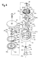
- Figure 3 schematically shows essential portions of the mounting portion 30.
- the mounting portion 30 includes a closed-end cylindrical body portion 31 having two cylindrical large and small accommodation spaces 31a and 31b therein, a cover member 33 covering the body portion 31, and a mounting shaft 35 for fastening the cover member 33 to the body portion 31.
- the winding body 32 is mounted rotatably in a cable winding direction (a direction indicated by a counterclockwise arrow C in Figure 3) and a cable releasing direction (a direction indicated by a clockwise arrow D in Figure 3).
- the mounting portion 30 includes a band 39 ( Figure 2) to be secured to the handlebar 4.
- a pair of protrusions 31c parallel to each other for preventing rotation of a positioning member 44 described later is formed in a bottom of the accommodation space 31b.
- the cover member 33 is a disk-shaped member, and covers an upper surface of the body portion 31.
- the mounting shaft 35 is a shaft member with steps, and extends upward through the body portion 31.
- a mounting bolt 37 is screwed into a tip of the mounting shaft 35 to cause the cover member 33 to cover the body portion 31.
- the mounting shaft 35 is the shaft with the steps having a small diameter portion 35a in the tip, a middle diameter portion 35b in the middle, a large diameter portion 35c in a base, and a flange 35d formed in the base, and the small diameter portion 35a, the middle diameter portion 35b, and the flange 35d have chamfers 35e, 35f and 35g parallel to one another for preventing rotation.
- the chamfer 35g engages the body portion 31 so that the mounting shaft 35 is nonrotatable with respect to the body portion 31.
- the winding body 32 is, for example, a ring-shaped metal member, and mounted to the accommodation space 31b rotatably on the protrusions 31c.
- the winding body 32 includes, in an outer peripheral surface thereof, an inner lock portion 32a that locks a cable nipple (not shown) secured to a tip of an inner cable 26a ( Figure 1) of the rear shift cable 26, and a cable winding groove 32b for winding the inner cable 26a.
- the winding body 32 is urged in the cable releasing direction by a torsion coil spring 50 (an example of a second urging member).
- the torsion coil spring 50 has one end locked to the winding body 32 and the other end locked to the positioning member 44 described later.
- a first ratchet 40 that constitutes the position holding and releasing mechanism 34 is formed in a first surface (a lower surface in Figure 3) of the winding body 32, and a second ratchet 42 that constitutes the position holding and releasing mechanism 34 is formed in a second surface (an upper surface in Figure 3) thereof.
- These ratchets 40 and 42 are formed in response to the number of shift steps and intervals between shift positions of the rear derailleur 18, and formed, with the same shape, in three positions at spaced intervals in a circumferential direction indicated by hatching in Figure 3.
- a fifth ratchet 80b that constitutes a third one-way clutch 80 described later is formed over the entire inner periphery of the first ratchet 40 in the lower surface of the winding body 32.
- the position holding and releasing mechanism 34 includes the first and second ratchets 40 and 42 that are moved integrally with the winding body 32, the positioning member 44 that engages the first ratchet 40 to hold the winding body 32 in any one of the plurality of (for example, nine) holding positions, and a releasing member 46 that releases positioning by the positioning member 44.
- the first and second ratchets 40 and 42 have serrated ratchet teeth 40a and 42a having different lock directions.
- the ratchet teeth 40a and 42 are schematically shown to have the same length in moving directions, but actually have different lengths in response to the intervals between the shift positions of the rear derailleur 18.
- the numbers of the ratchet teeth 40a and 42a are determined in response to the number of the shift steps.
- the cable winding direction is a right direction
- the cable releasing direction is a left direction. As described above, the winding body 32 is urged in the cable releasing direction (the left direction in Figure 4).
- each ratchet tooth 40a for positioning has, on a left side thereof, a vertical surface 40b that engages the positioning member 44 for positioning the winding body 32 against an urging force of the torsion coil spring 50, and an inclined surface 40c on a right side.
- each ratchet tooth 42a has a vertical surface 42b on a right side, and an inclined surface 42c on a left side.
- the positioning member 44 is mounted to the accommodation space 31 b of the body portion 31 nonrotatably and vertically movably.
- the positioning member 44 is, for example, a disk-shaped member having chamfers 44a parallel to each other in opposite positions.
- the chamfers 44a engage the protrusions 31c, and the positioning member 44 is accommodated nonrotatably and vertically movably in the body portion 31.
- On an upper surface of the positioning member 44 for example, three rod-shaped contact members 52 contactable with the releasing member 46 are provided in a standing manner.
- the positioning member 44 has positioning pawls 44b that engage the first ratchet 40 in an upper surface thereof.
- the positioning pawls 44b are placed in three positions at circumferentially spaced intervals (one position is not shown) and formed to be folded and protrude upward.
- the positioning pawl 44b has a shape of the ratchet tooth 40a with a slightly smaller size and a lower height.
- the positioning member 44 is urged by, for example, three coil springs 54 in a direction approaching the winding body 32.
- the coil springs 54 are placed at circumferentially spaced intervals, and mounted to the bottom of the body portion 31.
- the positioning member 44 also has a lever accommodating recess 44c that accommodates the winding lever 38 while limiting an oscillation range thereof to within a predetermined range.
- the releasing member 46 is a disk-shaped member, and placed above the winding body 32.
- the releasing member 46 is mounted vertically movably to the accommodation space 31a having a large diameter on an upper side of the body portion 31.
- the releasing member 46 engages the chamfer 35f formed in the middle diameter portion 35b of the mounting shaft 35 and is nonrotatably mounted to the mounting shaft 35.
- the releasing member 46 moves downward in Figure 3 to release the engagement between the first ratchet 40 and the positioning member 44.
- the releasing member 46 is urged upward to a drive member 62 described later of the releasing lever 36 by coil springs 56 (an example of a second urging member).
- the coil springs 56 are mounted to a step portion between the accommodation space 31a and the accommodation space 31 b of the body portion 31.
- the releasing member 46 has releasing pawls 46a that engage the second ratchet 42 in a lower surface thereof.
- the releasing pawls 46a are placed in three positions at circumferentially spaced intervals (one position is not shown) and formed to be folded and protrude downward.
- Each releasing pawl 46a has a height slightly lower than that of the ratchet tooth 42a of the second ratchet 42.
- second angle protrusions 46b that engage first angle protrusions 62a formed in the drive member 62 described later of the releasing lever 36 are formed over the entire periphery of an upper surface of the releasing member 46.
- Each second angle protrusion 46b has a shape of an isosceles triangle having second inclined surfaces 46c on opposite sides.
- a disk-shaped contact portion 46d contactable with the contact member 52 is formed in the center.
- the releasing lever 36 is mounted to the mounting portion 30 movably in a first direction (a direction indicated by a counterclockwise arrow A in Figure 3) and a second direction (a direction indicated by a clockwise arrow B in Figure 3), and operates the position holding and releasing mechanism 34 in response to the movement in the first direction and the second direction to move the winding body 32 in the cable releasing direction.
- the releasing lever 36 includes a lever member 60 (an example of an input member) movable in the first direction and the second direction around the mounting shaft 35, and the drive member 62 moved by the lever member 60 to operate the position holding and releasing mechanism 34.
- the lever member 60 is oscillably mounted to a step portion between the small diameter portion 35a at the tip of the mounting shaft 35 and the middle diameter portion 35b.
- An oscillation range of the lever member 60 is limited by a first notch 31d formed in the body portion 31.
- the lever member 60 has a sufficient length to protrude outside of the body portion 31, and has an operation portion 60a for a releasing operation in a tip thereof.
- a support hole 60b mounted to the small diameter portion 35a of the mounting shaft 35 is also formed in a base of the lever member 60.
- the lever member 60 is urged toward a neutral position by a pair of coil springs 64 placed on opposite sides thereof, and oscillated from the neutral position in both the first direction (a right direction indicated by an arrow A in Figure 10) and the second direction (a left direction indicated by an arrow B in Figure 10).
- An unshown positioning member for positioning the lever member 60 in the neutral position is placed between the lever member 60 and the small diameter portion 35a of the mounting shaft 35.
- the positioning member has, for example, a positioning pin mounted to the small diameter portion 35a retractably in a diametrical direction, and a positioning hole formed in an inner peripheral surface of the support hole 60b in engagement with the positioning pin.
- a first one-way clutch 66 and a second one-way clutch 68 are placed between the lever member 60 and the drive member 62.
- the first one-way clutch 66 transmits only the movement of the lever member 60 in the first direction to the drive member 62
- the second one-way clutch 68 transmits only the movement of the lever member 60 in the second direction to the drive member 62.
- the first and second one-way clutches 66 and 68 include ratchet pawls 66a and 68a mounted to a lower surface of the lever member 60 oscillably to a standing position and a lying position, third and fourth ratchets 66b and 68b formed in an upper surface of the drive member 62 with lock surfaces 66c and 68c formed in different directions, and coil springs 66d and 68d that urge the ratchet pawls 66a and 68a toward the standing position.
- the ratchet pawls 66a and 68a are formed over the entire periphery of the upper surface of the drive member 62, and the ratchet pawl 68a is formed on an inner peripheral side of the ratchet pawl 66a.
- the first and second one-way clutches 66 and 68 include pressure plates 70 for preventing transmission of a one-way clutch 66 or 68 in an opposite direction to a moving direction when the lever member 60 is moved from the neutral position.
- the ratchet pawl 68a of the second one-way clutch 68 is pressed to the lying position by the pressure plate 70 to prevent the second one-way clutch 68 from being operated to transmit only the movement of the lever member 60 in the first direction A to the drive member 62.
- the pressure plate 70 is nonrotatably mounted to the mounting shaft 35.
- the drive member 62 is a ring-shaped member, and has the third and fourth ratchets 66b and 68b that constitute the first and second one-way clutches 66 and 68 formed in the upper surface thereof.
- the first angle protrusions 62a that engage the second angle protrusions 46b formed in the releasing member 46 are formed in the lower surface of the drive member 62.
- each first angle protrusion 62a has a shape of an isosceles triangle having first inclined surfaces 62b on opposite sides, and like a vertically inverted shape of the second angle protrusion 46b. The engagement between these triangles allows the releasing member 46 to be vertically moved to perform the same releasing operation when the drive member 62 is moved in any of the first direction and the second direction.
- the winding lever 38 moves the winding body 32 in the cable winding direction.
- the winding lever 38 is accommodated in the lever accommodating recess 44c of the positioning member 44 between the positioning member 44 and the winding body 32, and oscillably mounted to a step portion between the middle diameter portion 35b and the large diameter portion 35c of the mounting shaft 35.
- An oscillation range of the winding lever 38 is limited by a second notch 31e formed in the body portion 31.
- the winding lever 38 extends in a different direction from the lever member 60 of the releasing lever 36, and has a sufficient length to protrude outside of the body portion 31.
- the winding lever 38 has an operation portion 38a for winding and releasing operations in a tip thereof.
- a support hole 38b mounted to the middle diameter portion 35b of the mounting shaft 35 is formed in a base of the winding lever 38.
- the winding lever 38 is urged to a clockwise operation start position in Figure 3 by a coil spring 72 placed on one side, and oscillated between the operation start position and an operation finish position limited by the second notch 31e. Then, after the operation, the winding lever 38 returns to the operation start position.
- a third one-way clutch 80 is placed between the winding body 32 and the winding lever 38. As shown in Figures 3 and 9, the third one-way clutch 80 is provided to transmit only a counterclockwise oscillation from the operation start position to the operation finish position of the winding lever 38 to the winding body.
- the third one-way clutch 80 includes a ratchet pawl 80a mounted to an upper surface of the winding lever 38 facing the winding body 32 oscillably to a standing position and a lying position, a fifth ratchet 80b formed in the lower surface of the winding body 32, and a coil spring 80d that urges the ratchet pawl 80a toward the standing position.
- the fifth ratchet 80b is formed over the entire inner periphery of the first ratchet 40 in the lower surface of the winding body 32.
- the third one-way clutch 80 includes a pressure plate 74 for preventing a power transmission operation in the operation start position.
- the pressure plate 74 is placed between the winding lever 38 and the winding body 32, made nonrotatable by the three contact members 52, and mounted to the contact members 52 vertically immovably.
- the front shift operation portion 15 has a structure similar to that of the rear shift operation portion 16 related as object and mirror image, and is provided inside the rear brake lever 12.
- an operation in the cable winding and releasing directions is operated by operating the lever member 60 of the releasing lever 36 in any of the first direction A and the second direction B.
- the lever member 60 is operated in the first direction A, for example, with a thumb
- the drive member 62 is also moved in the first direction A via the first one-way clutch 66.
- the drive member 62 is also moved in the second direction B via the second one-way clutch 68.
- the first angle protrusion 62a is moved to the right in Figure 4, and as shown in Figures 5 and 6, the first inclined surface 62b presses the second inclined surface 46c of the second angle protrusion 46b to move the releasing member 46 downward.
- the positioning member 44 is gradually moved downward via the contact member 52, the positioning pawl 44b is removed from the first ratchet 40, and the releasing pawl 46a engages the second ratchet 42. Then, the positioning pawl 44b is completely removed from the first ratchet 40 immediately before apexes of the angle protrusions 62a and 46a come into contact with each other.
- Figure 6 schematically shows an instance of the positioning pawl 44b being removed from the first ratchet 40.
- the winding body 32 urged in the cable releasing direction D by the torsion coil spring 50 is slightly moved in the cable releasing direction D until the inclined surface 42c of the second ratchet 42 comes into contact with a rear surface of the releasing pawl 46a.
- This state is shown in Figure 7.
- an urging force of the coil spring 56 raises the releasing member 46
- an urging force of the coil spring 54 raises the positioning member 44.
- the winding body 32 is slightly moved in the cable releasing direction when the positioning pawl 44b is removed, and thus as shown in Figure 7, the positioning pawl 44b is placed in a position facing the next succeeding ratchet tooth 40a in the cable releasing direction D rather than the ratchet tooth 40a previously locked by the positioning pawl 44b, and can lock the succeeding ratchet tooth 40a. Then, as shown in Figure 8, when the two angle protrusions 62a and 46b return to the state of substantially coming into contact with each other, the releasing pawl 46a is removed from the second ratchet 42, and the winding body 32 is moved (rotated) by one tooth in the cable releasing direction D.
- a shift operation for a plurality of shift steps can be collectively performed in response to the amount of movement of the drive member 62.
- the releasing member 62 is similarly lowered and raised, and the winding body 32 is moved in the cable releasing direction D through the operation as described above.
- the cable releasing operation can be performed when the lever member 60 of the releasing lever 36 is operated in any of the first direction and the second direction, and thus the operation direction of the cable releasing operation by the lever member 60 can be suited to rider's preference.
- the operation in the cable winding direction is performed by pressing the winding lever 38 to the right in Figure 9 (counterclockwise in Figure 3) from the operation start position to the operation finish position as shown in Figure 9.
- the winding lever 38 is pressed, the winding body 32 is moved in the cable winding direction, that is, to the right in Figure 4 by the third one-way clutch 80, and the first ratchet 40 presses the positioning pawl 44b downward to position the positioning pawl 44b in the next shift position in the winding direction.
- a shift operation for a plurality of shift steps can be collectively performed in response to the amount of movement of the winding lever 38.
- the position holding and releasing mechanism 34 is moved perpendicularly to the surface of rotation of the winding body 32, while in a second embodiment, as shown in Figure 11, a position holding and releasing mechanism 134 is moved along a surface (PI) parallel to a surface of rotation of a winding body 132 in a rear shift operation portion 116.
- the rear shift operation portion 116 includes a mounting portion 130 having the same outer shape as the mounting portion 30 in Figure 2.
- the rear shift operation portion 116 includes a support shaft 131 connected to the mounting portion 130 and extending in a direction of a first axis X1, the winding body (an example of a cable lock body) 132 mounted rotatably around the first axis X1 movably in a cable pulling direction and a cable releasing direction of a shift cable 26, the position holding and releasing mechanism 134 that selectively holds the winding body 132 in any one of a plurality of holding positions corresponding to a plurality of shift positions, a releasing lever 35 for an operation in the cable releasing direction, and a winding lever 138 in Figure 2 for an operation in the cable pulling direction.
- main portions of the rear shift operation portion 116 according to the present invention are shown in an inverted position from that shown in Figure 2.
- the mounting portion 130 mainly includes a casing 140 (Figure 2), for example, of synthetic resin mountable to a handlebar 4 and having a space therein, and a mounting bracket 141 ( Figures 11 to 13) provided in the space in the casing 40.
- the mounting bracket 141 is a metal plate member, and the support shaft 131 is nonrotatably connected to the mounting bracket 141.
- the position holding and releasing mechanism 134, the releasing lever 135, the winding lever 138, and a drive mechanism 139 are movably connected to the mounting bracket 141. Configurations thereof and detailed connecting structures to the mounting bracket 141 will be described together with descriptions of each component.
- the support shaft 131 is placed in the direction of the first axis X1 that passes through a slot-shaped opening 141a of the mounting bracket 141 in Figure 11.
- a circular head 131 a is formed in a base (an upper end in Figure 11) of the support shaft 131, and a rotation support portion 131 c having chamfered portions 131 b parallel to each other at a lower end is formed in the middle thereof.
- a male screw 131d is formed in a lower portion, and a female screw 131e is formed in the head 131a.
- An unshown bolt is screwed into the female screw through the casing 140 to secure the support shaft 131 to the mounting portion 130.
- the support shaft 131 is nonrotatably connected to the mounting bracket 141 with the chamfered portions 131 b engaging the opening 141a.
- the winding body 132 is, for example, a member of synthetic resin such as polyacetal, placed on a first surface (an upper surface in Figure 11) of the mounting bracket 141, and mounted to the rotation support portion 131 c of the support shaft 131 via a bush 152 movably (rotatably) in a cable winding direction and the cable releasing direction.
- the winding body 132 includes, in an outer peripheral surface thereof, an inner lock portion 132a that locks a cable nipple 26c secured to a tip of an inner cable 26a of the rear shift cable 26, and a cable winding groove 132b for winding the inner cable 26a.
- the winding body 132 is urged in the cable releasing direction (clockwise in Figure 11) by a spring member 150, for example, in the form of a spiral spring.
- the spring member 150 has one end locked to the winding body 132 and the other end locked to the mounting bracket 141.
- four engaging protrusions 132c are formed that are interlocked with and rotate a positioning unit 154 described later of the position holding and releasing mechanism 134.
- One of the four engaging protrusions 132c has a circumferential length different from the lengths of the others. This allows rotation phases of the positioning unit 154 and the winding body 132 to be reliably matched.
- the position holding and releasing mechanism 134 is placed on the side of the first surface of the mounting bracket 141.
- the position holding and releasing mechanism 134 includes the positioning unit 154 that has, for example, nine positioning teeth 162 and eight advance teeth 164 and is interlocked with the winding body 132, and a positioning pawl 156 that oscillates between a first engaging position in Figure 12 for engagement with the positioning teeth 162 and a first releasing position in Figure 16 for release from the positioning teeth 162.
- the position holding and releasing mechanism 134 includes a rotation preventing pawl 157 that oscillates between a second engaging position in Figure 16 for engagement with the positioning teeth 162 in a position different from the positioning pawl 156 and a second releasing position in Figure 12 for release from the positioning teeth 162, and an advance pawl 159 that engages and is separated from the advance teeth 164.
- the positioning unit 154 is placed in contact with the upper surface of the winding body 132 in Figure 11.
- the positioning unit 154 has an engaging hole 154a that engages the engaging protrusion 132c of the winding body 132, and is integrally rotated with the winding body 132.
- the positioning teeth 162 and the advance teeth 164 are provided of the numbers corresponding to the number of shift positions of a rear derailleur 18, and formed in an outer peripheral surface of the positioning unit 154 so as to radially protrude.
- the positioning unit 154 is urged in the cable releasing direction (clockwise in Figure 11) together with the winding body 132 by the spring member 150.
- the positioning teeth 162 and the advance teeth 164 are spaced based on the amount of movement of the cable set according to the shift positions of the rear derailleur 18.
- the positioning pawl 156 is oscillably mounted to a second oscillation shaft 165 provided to pass through the mounting bracket 141 and placed along a second axis X2 parallel to the first axis X1.
- the second oscillation shaft 165 passes through the mounting bracket 141 and extends downward.
- the positioning pawl 156 is urged counterclockwise in Figure 11 so as to be placed in the first engaging position by a spring member (an example of a second urging member) 158, for example, in the form of a torsion coil spring.
- the positioning pawl 156 includes a first pawl portion 156a that comes into contact with a lock surface 162a of the positioning teeth 162 and prevents the positioning unit 154 urged clockwise from being rotated in the cable releasing direction, a pair of regulating protrusions 156b and 156c for regulating an oscillation range of the rotation preventing pawl 157, and an engaging protrusion 156d that engages the drive mechanism 139.
- the first pawl portion 156a is formed to protrude toward the positioning unit 154 in a tip extending from the center of rotation along the positioning unit 154.
- the pair of regulating protrusions 156b and 156c extend on the opposite side of the first pawl portion 156a with a space therebetween.
- the regulating protrusion 156b is formed in a position such that the rotation preventing pawl 157 is placed in the second releasing position when the positioning pawl 156 is placed in the first engaging position.
- the regulating protrusion 156c is provided so that the rotation preventing pawl 157 can release the engagement between a second arm member 171 of the drive mechanism 139 described later and the positioning pawl 156 by the oscillation within a predetermined range.
- the engaging protrusion 156d slightly protrudes toward the second arm member 171 so as to be engageable with three operation portions 171 a to 171 c of the second arm member 171.
- the rotation preventing pawl 157 is rotatably mounted to the second oscillation shaft 165 below the positioning pawl 156, and oscillable within the predetermined range (for example, within a range of 5 to 10 degrees) relative to the positioning pawl 156.
- the rotation preventing pawl 157 has a second pawl portion 157a that is bent upward from below the positioning pawl 156 in Figure 11 and engages the positioning teeth 162, a regulating portion 157b bent upward so as to be placed between the pair of regulating protrusions 156b and 156c, and a release cam portion 157c that can abut against the three operation portions 171a to 171c of the second arm member 171.
- the regulating portion 157b is formed to come into contact with the regulating protrusion 156b when the positioning pawl 156 is moved from the first releasing position in Figure 16 to the first engaging position in Figure 12 to allow the rotation preventing pawl 157 to be moved from the second engaging position to the second releasing position.
- the release cam portion 157c is formed to be moved from the second releasing position to the second engaging position together with the positioning pawl 156 when the positioning pawl 156 is moved from the first engaging position to the first releasing position by the drive mechanism 39.
- the release cam portion 157c is provided, when in the second engaging position, to release the engagement between the positioning pawl 156 and the drive mechanism 139 when the positioning teeth 162 comes into contact with the second pawl portion 157a to cause the rotation preventing pawl 157 to be rotated within the predetermined range. As shown in Figure 16, the release cam portion 157c overlaps the regulating protrusion 156c and is hidden when the regulating portion 157b comes into contact with the regulating protrusion 156b.
- the rotation preventing pawl 157 comes into contact with a positioning tooth 162c upstream in the cable releasing direction by one of a positioning tooth 162b with which the positioning pawl 156 has been in contact, and prevents the positioning unit 154 from being continuously rotated in the cable releasing direction at a stroke after the positioning pawl 156 is separated.
- the positioning pawl 156 is placed in a position passing over the positioning tooth 162b that the positioning pawl 156 has engaged as shown in Figure 12.
- the advance pawl 159 is oscillably mounted to an oscillation shaft 167 standing on the winding lever 138.
- the advance pawl 159 is urged counterclockwise in Figure 12 by a spring member (not shown) such as a torsion coil spring so that the advance pawl 159 is placed in an advance position.
- the advance pawl 159 is placed in a position spaced apart from the advance teeth 164 by a holding plate 161 provided in the mounting bracket 141 when the winding lever 138 is placed in an operation start position. Then, when the winding lever 138 is operated, the advance pawl 159 engages the advance teeth 164 from an end of the holding plate 161 to rotate the positioning unit 154 in the cable pulling direction (counterclockwise in Figure 12).
- the releasing lever 135 includes the lever member (an example of an input member) 136 for the cable releasing operation, and the drive mechanism (an example of a drive member) 139 for causing the position holding and releasing mechanism 34 to perform the releasing operation for the plurality of shift steps with one operation of the lever member 136.
- the lever member 136 is placed in a second surface (a lower surface in Figure 11) of the mounting bracket 141.
- the lever member 136 can cause the position holding and releasing mechanism 134 to perform the releasing operation via the drive mechanism 139 according to any of operations in a first direction, clockwise and a second direction, counterclockwise in Figure 11.
- the lever member 136 oscillates from a neutral position in Figure 13 in the second direction (clockwise in Figure 13) around the second oscillation shaft 165 protruding on the side of the second surface of the mounting bracket 141.
- the lever member 136 also oscillates in the first direction (counterclockwise in Figure 13) around the first oscillation shaft 166 that is spaced apart from the second oscillation shaft 165 and on which a first arm member 170 of the drive mechanism 139 is oscillably supported.
- the first oscillation shaft 166 is placed along a third axis X3 parallel to the first axis X1.
- the lever member 136 is urged toward the support shaft 131 via the drive mechanism 139.
- the lever member 136 is urged so that the first and second oscillation shafts 166 and 165 are placed in one ends (lower ends in Figure 13) of first and second slots 136c and 136d described later. In this embodiment, the lever member 136 is urged toward the support shaft 131.
- the lever member 136 has an operation knob 136a, and a lever portion 136b connected to the knob 136a.
- the knob 136a is made of, for example, synthetic resin or die cast metal, and has, on opposite sides thereof, first and second operation surfaces 136f and 136g for operations in the first and second directions so as to facilitate the operations in the first and second directions.
- the lever portion 136b is made of, for example, metal such as stainless steel alloys or steel, and slightly bent in the middle so as to be placed around the support shaft 131.
- the first and second slots 136c and 136d having arcuate shapes and semicircular opposite ends are formed in a base and a tip side thereof of the lever portion 136b.
- the first slot 136c is formed by an arc around a semicircle at one end (a lower end in Figure 13) of the second slot 136d
- the second slot 136d is formed by an arc around a semicircle at one end (a lower end in Figure 13) of the first slot 136c.
- an acting portion 136e for operating the drive mechanism 139 is formed in one edge (a lower side in Figure 13) of the lever portion 136b.
- the acting portion 136e is always in contact with the first arm member 170 of the drive mechanism 139 that urges the lever member 136 toward the support shaft 131.
- the first slot 136c engages the first oscillation shaft 166
- the second slot 136d engages the second oscillation shaft 165.
- widths of the slots 136c and 136d are slightly larger than diameters of the oscillation shafts 166 and 165.
- the oscillation shafts 165 and 166 pass through through holes 141c and 141d formed in the mounting bracket 141 and extend downward, and have lower ends secured by a support plate 169 spaced apart from the first surface of the mounting portion bracket 141.
- the lever member 136 urged toward the support shaft 131 oscillates from the neutral position in which one ends (the lower ends in Figure 13) of the slots 136c and 136d come into contact with the oscillation shafts 166 and 165 in any of the first direction in Figure 14 and the second direction in Figure 15.
- the first oscillation shaft 166 is the center of oscillation
- the second oscillation shaft 165 is the center of oscillation as described above.
- the acting portion 136e operates in the same manner, and causes the drive mechanism 139 to perform the same operation.
- the lever member 136 can perform the same multistage releasing operation by the operations from the neutral position in both the first and second directions.
- the winding lever 138 is placed above the positioning unit 154 in Figure 11, and oscillably mounted to the support shaft 131 from the operation start position in an operation finish direction. As described above, the advance pawl 159 is oscillably placed in the middle of the winding lever 138. The winding lever 138 is urged toward the operation start position by an unshown spring member.
- the drive mechanism 139 is movably connected to the first surface of the mounting bracket 141 in the position spaced apart from the support shaft 131.
- the drive member that is, the drive mechanism 139 includes the first arm member 170 oscillably mounted to the first oscillation shaft 166, and the second arm member 171 oscillably mounted to the first arm member 170.
- the first arm member 170 includes a lock portion 170a that branches on the way to the second arm member 171, a connecting portion 170b that oscillably connects the second arm member 171, and a support portion 170c for preventing rattling during the oscillation of the first and second arm members 170 and 171.
- the lock portion 170a branches on the way, passes through the opening 141 b formed in the mounting bracket 141, and extends on the side of the second surface.
- the acting portion 136e of the lever member 136 comes into contact with a tip of the lock portion 170a.
- the first arm member 170 is interlocked with the acting portion 136e moved by the operation of the lever member 136 and oscillates.
- the first arm member 170 is urged counterclockwise in Figure 12 by a spring member 174 locked to the second arm member 171.
- the urging force is transmitted to the lever member 136 via the acting portion 136e to urge the lever member 136 toward the support shaft 131.
- a third oscillation shaft 168 stands on the connecting portion 170b.
- the support portion 170c extends to overlap an oscillation range of the second arm member 171, and comes into contact with the second arm member 171 to prevent rattling of the second arm member 171.
- a contact protrusion 170d that comes into contact with the first surface of the mounting bracket 141 is formed in a lower surface of the support portion 170c. This also reduces rattling of the first arm member 170 during the oscillation.
- the second arm member 171 has the plurality of (for example, three) operation portions 171a to 171c at a tip thereof.
- the three operation portions 171a to 171c allow the drive mechanism 139 to perform three multistage releasing operations at the maximum with one operation of the lever member 136 in the first direction or the second direction, that is, continuous shifting for three shift steps.
- the movement of the inner cable 26a in the cable releasing direction causes the rear derailleur 18 to perform shifting up, and when the current shift step is the ninth step, the gear can be shifted to the sixth step at a stroke.
- each of the operation portions 171a to 171c includes an engaging portion 172 that engages the engaging protrusion 156d of the positioning pawl 156, and an engagement releasing portion 173 that comes into contact with the release cam portion 157c to release the engagement with the positioning pawl 156 at the engaging portion 172 by the oscillation of the rotation preventing pawl 157 within the predetermined range.
- the engagement releasing portion 173 is provided axially adjacent to the engaging portion 172.
- the second arm member 171 is urged in a direction approaching the positioning pawl 156 by a spring member (an example of a third urging member) 174, for example, in the form of a coil spring.
- the first arm member 170 is also urged in a direction approaching the positioning unit 154 by the spring member 174, and further, the lever member 136 is urged in a direction approaching the support shaft 131.
- the spring member 174 is locked to a lock pin 171d having one end protruding toward the mounting bracket 41 near the operation portion 171a of the second arm member 171 and the other end locked to the mounting bracket 141.
- the spring member 174 collectively urges the three members 171, 170, and 136.
- the front shift operation portion and the rear shift operation portion 116 are related as object and mirror image and have substantially the same structure as in the first embodiment except the number of shift steps, and the front shift operation portion is provided inside the rear brake lever 12.
- the engaging portion 172 of the operation portion 171a of the second arm member 171 engages the engaging protrusion 156d of the positioning pawl 156 to cause the positioning pawl 156 to oscillate clockwise around the second oscillation shaft 165 from the first engaging position in Figure 12 to the first releasing position in Figure 16.
- the operation portion 171a also comes into contact with the release cam portion 157c of the rotation preventing pawl 157 to cause the rotation preventing pawl 157 to oscillate from the second releasing position in Figure 12 to the second engaging position in Figure 16.
- the positioning unit 154 urged in the cable releasing direction clockwise in Figure 16 by the spring member 150 via the winding body 132 is rotated in the cable releasing direction, and the positioning tooth 162c downstream in the rotational direction by one of the positioning tooth 162b positioned by the positioning pawl 156 comes into contact with the second pawl portion 157a of the rotation preventing pawl 157. Then, the rotation preventing pawl 157 is oscillable relative to the positioning pawl 156 within the predetermined range, and thus the rotation preventing pawl 157 pressed by the positioning tooth 162c oscillates counterclockwise.
- the operation portion 171b causes the positioning pawl 156 to oscillate to the first releasing position to rotate the positioning unit 154 in the cable releasing direction like the operation described above, and the positioning tooth 162b further presses the rotation preventing pawl 157 to cause the rotation preventing pawl 157 to oscillate within the predetermined range to release the engagement between the operation portion 171b and the positioning pawl 156.
- the positioning unit 154 is further rotated in the cable releasing direction by one shift step until the positioning pawl 156 comes into contact with a positioning tooth 162e.
- the positioning unit 154 is further rotated in the cable releasing direction by one shift step with the same operation.
- the releasing operation can be repeated until the engagement of the engagement releasing portion 173 of the operation portion 171c is released.
- the second arm member 171 urged by the spring member 174 returns to the position in Figure 12.
- the second arm member 171 returns to the position in Figure 12 while being in contact with the outer periphery of the regulating protrusion 156c of the positioning pawl 156, but the second arm member 171 does not act on the positioning pawl 156.
- the release cam portion 157c of the rotation preventing pawl 157 is formed to be hidden by the regulating protrusion 156c in this state, and thus the second arm member 171 does not act on the rotation preventing pawl 157. This prevents the cable releasing operation.
- the advance pawl 159 presses the advance teeth 164 to rotate the positioning unit 154 in the cable winding direction (counterclockwise in Figure 12). Then, the positioning teeth 162 come into contact with the positioning pawl 156 to press the positioning pawl 156 toward the first releasing position. When the pressed positioning teeth 162 pass through the positioning pawl 156, however, the positioning teeth 156 return to the first engaging position.
- multistage winding operations for example, of four steps can be performed.
- the spring member 174 urges the lever member 136, the first arm member 170, and the second arm member 171, but each member may be urged by each spring member.
- the input member that oscillates with the two oscillation shafts 165 and 166 in the plane parallel to the first plane (P) is exemplified, but a joystick-shaped input member may be used.
- a mounting portion 230 includes a bracket 240, for example, made of a metal plate mountable to a handlebar 4 by a fastening bolt, a first cover 242 mounted to one side of the bracket 240, and a second cover 244 mounted to the other side of the bracket 240.
- the bracket 240 has a plane 240a on which a winding body 232 is placed, and an opening 240b in which a rotation shaft 246 is nonrotatably mounted.
- the rotation shaft 246 passes through the opening 240b of the bracket 240 and extends upward.
- a tip of the rotation shaft 246 is secured by a securing bolt 241 to secure the second operating member 238.
- the bracket 240 has a female screw 240c into which an outer lock portion 227 for locking an outer casing 26b ( Figure 23) of a rear shift cable 26 is screwed.
- the winding body 232 is movable along a first plane (P) parallel to the plane 240a of the bracket 240. Specifically, the winding body 232 is mounted to the rotation shaft 246 via a bush 252 movably (rotatably) in a cable winding direction and a cable releasing direction.
- the winding body 232 includes, in an outer peripheral surface thereof, an inner lock portion 232a that locks a cable nipple 26c secured to a tip of an inner cable 26a ( Figure 1) of the rear shift cable 26, and a cable winding groove 232b for winding the inner cable 26a.
- the winding body 232 is urged in the cable releasing direction (couterclockwise in Figure 24) by a spring member 250 such as a torsion coil spring.
- the spring member 250 has one end locked to the winding body 232 and the other end locked to the bracket 240 described later.
- an engaging protrusion 232c is formed that is interlocked with and rotate a positioning unit 254 described later of the position holding and releasing mechanism 234.
- the position holding and releasing mechanism 234 includes the positioning unit 254 that has, for example, eight positioning teeth 262 and eight advance teeth 264 and is interlocked with the winding body 232, and a positioning pawl 256 that is moved along a surface parallel to the first plane (P) between an engaging position in Figure 25A for engagement with the positioning teeth 262 and a releasing position in Figure 25B for release from the positioning teeth 262.
- the position holding and releasing mechanism 234 includes a rotation preventing pawl 257 that is moved along a surface parallel to the first plane (P) between a contacting position in Figure 25B for engagement with the positioning teeth 262 in a position different from the positioning pawl 256 and a separating position in Figure 25A for separation from the positioning teeth 262, an advance pawl 259 that is moved between an advance position for engagement with the advance teeth 64 shown by a dash-double-dot line in Figure 24 and a releasing position for separation shown by a solid line in Figure 24, and a holding plate 261 nonrotatably mounted to the rotation shaft 246.
- the positioning unit 254 has an engaging hole 254a that engages the engaging protrusion 232c of the winding body 32, and is integrally moved with the winding body 232.
- the positioning teeth 262 and the advance teeth 264 are provided of the numbers corresponding to the number of shift positions of a rear derailleur 18, and formed in an outer peripheral surface of the positioning unit 254 so as to radially protrude.
- the positioning unit 254 is urged in the cable releasing direction (couterclockwise in Figure 24) together with the winding body 232 by the spring member 250.
- the positioning teeth 262 and the advance teeth 264 are spaced based on the amount of movement of the cable set according to the shift positions of the rear derailleur 18.
- the positioning pawl 256 and the rotation preventing pawl 257 are integrally formed in an oscillation unit 255 oscillably mounted to an oscillation shaft 265 standing on the bracket 240.
- the oscillation unit 255 is urged clockwise in Figure 24 by a spring member 258 such as a torsion coil spring so that the positioning pawl 256 is placed in the engaging position.
- the positioning pawl 256 comes into contact with a lock surface 262a of the positioning teeth 262 and prevents the positioning unit 256 urged counterclockwise from being rotated in the cable releasing direction.
- the rotation preventing pawl 257 when moved to the contacting position, comes into contact with a positioning tooth 262c downstream in the cable releasing direction by one of a positioning tooth 262b with which the positioning pawl 256 has been in contact, and prevents the positioning unit 254 from being continuously rotated in the cable releasing direction at a stroke after the positioning pawl 256 is separated.
- the positioning pawl 256 is placed in a position passing over the positioning tooth 262b that the positioning pawl 256 has engaged as shown in Figure 25B.
- the advance pawl 259 is oscillably mounted to an oscillation shaft 266 standing on the second operating member 238.
- the advance pawl 259 is urged clockwise in Figure 24 by a spring member 267 such as a torsion coil spring so that the advance pawl 259 is placed in the advance position.
- the holding plate 261 is nonrotatably mounted to the rotation shaft 246 and secured to an upper end of the oscillation shaft 265 by a snap ring 263.
- the holding plate 261 has an abutting portion 261a for placing the advance pawl 259 in the releasing position when the second operating member 238 is placed in an operation start position described later so as to protrude toward the advance pawl 259.
- the advance pawl 259 is always placed in the releasing position when the second operating member 238 is placed in the operation start position.
- a first operating member 236 includes an input member 268 movable (oscillable) in any directions including a first direction and a second direction shown by dash-double-dot lines in Figure 22, and a drive member 270 that is moved by the input member 268 to move the positioning pawl 256 from the engaging position to the releasing position.
- the input member 268 is a joystick-shaped member, and has a knob 268a and a spherical portion 268b formed in a base of the knob 268a.
- An outer peripheral surface of the spherical portion 268b is formed by a spherically curved surface.
- a periphery of the spherical portion 268b is covered with a case member 269 secured to the bracket 240.
- a spherical guide surface 269a that tiltably guides the spherical portion 268b is formed inside the case member 269.
- the input member 268 is urged toward the neutral position in Figure 25A by the spring member 258 that urges the oscillation unit 255, and can oscillate in all directions including the first direction and the second direction from the neutral position around the center of the peripheral portion 268b.
- the drive member 270 includes a first link member 270a (an example of a connecting member) connected to the outer periphery of the spherical portion 268b of the input member 268 by a universal joint 272a, and a second link member 270b (an example of a connecting member) rotatably connected to the first link member 270a.
- the second link member 270b is connected to the oscillation unit 255 via a universal joint 272b.
- the knob 268a of the input member 268 is tilted in one direction by hand to cause the spherical portion 268b to oscillate around a base of the guide surface 269a.
- the drive member 270 connected to the center thereof is pulled to cause the oscillation unit 255 to oscillate counterclockwise in Figure 24, and move the positioning pawl 256 from the engaging position to the releasing position.
- the input member 268 is returned to the neutral position by the spring member 271.
- the oscillation unit 55 is urged so that the positioning pawl 256 is placed in the engaging position by the spring member 58, and thus the oscillation unit 255 oscillates clockwise to again place the positioning pawl 256 in the engaging position.
- the second operating member 238 is mounted to the rotation shaft 246 oscillably to the operation start position shown by a solid line in Figure 22 and the operation finish position shown by a dash-single-dot line.
- the second operating member 238 is urged toward the operation start position by a spring member 275 such as a spiral spring.
- a knob 238a is provided in one end of the second operating member 238.
- the oscillation shaft 266 that supports the advance pawl 259 stands on the side of the other end of the second operating member 238 with the center of oscillation therebetween.
- the front shift operation portion 215 and the rear shift operation portion 216 are related as object and mirror image and have the same structure as in the first embodiment, and the front shift operation portion 215 is provided inside the rear brake lever 212.
- the positioning unit 254 is urged in the cable releasing direction by the spring member 250, and thus the positioning unit 254 is rotated in the cable releasing direction.
- the rotation preventing pawl 257 integrally formed with the positioning pawl 256 in the oscillation unit 255 is moved to the contacting position.
- the positioning unit 254 is stopped in a position where the positioning pawl 256 passes over the positioning tooth 262b that the positioning pawl 256 has engaged.
- the input unit 268 is returned to the neutral position by the spring member 258.
- the oscillation unit 255 is urged so that the positioning pawl 256 is placed in the engaging position by the spring member 258, and thus the oscillation unit 255 oscillates clockwise as shown in Figure 25C to again place the positioning pawl 256 in the engaging position.
- the positioning unit 254 is rotated in the cable releasing direction by one tooth of the positioning teeth 262 and stopped, and the winding body 232 is also rotated in the cable releasing direction by one shift position.
- the winding body 232 can be moved in the cable releasing direction by the movement of the first operating member 236 in any of the first direction and the second direction, and thus the operating direction of the first operating member 236 can be suited to rider's preference. Also, the winding body 232 and the positioning pawl 256 are placed in parallel, which can make the shift operation portion 216 compact.
- the advance pawl 259 is urged by the spring member 267 and moved to the advance position to engage the advance teeth 264 as shown in Figure 26A at the time of the tip of the advance pawl 259 passing through the abutting portion 261a.
- the oscillation of the second operating member 238 causes the positioning unit 254 to be rotated in the cable winding direction (clockwise in Figure 26).
- the positioning pawl 256 is placed in the engaging position until the positioning unit 254 is rotated, and is pressed by the positioning tooth 262c next to the positioning tooth 262b positioned and moved toward the releasing position according to the oscillation of the second operating member 238 as shown in Figure 26B.
- the first and second link members 270a and 270b of the drive member 270 are bent at connecting portions and sag to prevent the input member 268 from being moved.
- the positioning tooth 262c passes over the positioning pawl 256, and the positioning pawl 256 is moved to the engaging position with the positioning tooth 262c as shown in Figure 26C.
- the positioning unit 254 is rotated in the cable winding direction by one tooth of the positioning teeth 262 and stopped, and the winding body 232 is also rotated in the cable winding direction by one shift position.
- the second operating member 238 is further caused to oscillate toward the operation finish position from the state in Figure 26C, the same operations as in Figures 26A to 26C are repeated, and the winding body can be further rotated in the cable winding direction by one tooth.
- the drive member 270 has the two link members 27a and 270b, but may have a tensionable and releasable member such as a wire or a rope instead of the link member.
Abstract
Description
- The present invention relates to a shift operation device, and more particularly to a shift operation device for a bicycle that is mounted to a frame of the bicycle for performing a shift operation for switching among a plurality of shift positions of a shift device connected by a shift cable.
- Some bicycles include a shift device such as an internal shift device or an external shift device. For a shift operation of such a shift device, a shift operation device connected to the shift device via a shift cable has been used. A conventionally known shift operation device is of an operation member type including a winding operation member and a releasing operation member in the form of an operation member that oscillates. As the shift operation device of the operation member type, a technique for oscillably operating the winding operation member and the releasing operation member in the same direction (for example, see
Japanese Patent No. 2730555 Japanese Patent No. 3065656 - In both the conventional techniques, the operation direction of the winding operation member is the direction of being pressed with the thumb. The operation direction of the releasing operation member is the same direction as the winding operation member in the former technique, and a different direction from the winding operation member in the latter technique. The operation directions of the winding operation member and the releasing operation member are sometimes desired to be changed in response to rider's preference. For both the conventional techniques, however, the operation direction of the operation member is limited to a fixed direction and cannot be suited to the rider's preference.
- An object of the present invention is to provide a shift operation device for a bicycle having an operation member that can suit an operation direction of the operation member to rider's preference.
- A shift operation device for a bicycle according to the invention 1 includes: a mounting portion mountable to the bicycle; a cable lock body; a position holding and releasing mechanism; and a first operation member. The cable lock body is mounted to the mounting portion movably to a cable pulling direction and a cable releasing direction. The position holding and releasing mechanism selectively holds the cable lock body in any one of a plurality of holding positions. The first operation member is mounted to the mounting portion movably in a first direction and a second direction, and operates the position holding and releasing mechanism in response to the movement in the first direction and the second direction to move the cable lock body in the cable releasing direction, respectively.
- In the shift operation device, when the first operation member is moved in the first direction or the second direction, the position holding and releasing mechanism is operated in response to the movement to move the cable lock body in the cable releasing direction. The cable lock body can be moved in the cable releasing direction when the first operation member is moved in any of the first direction and the second direction, and thus an operation direction of a cable releasing operation by the first operation member can be suited to rider's preference.
- For the shift operation device for a bicycle according to the invention 2, in the device according to the invention 1, the position holding and releasing mechanism can shift the holding position of the cable lock body by a plurality of positions in response to the movement of the first operation member in at least any one of the first direction and the second direction. In this case, shift by the plurality of positions can be collectively performed, and thus a plurality of steps of the shift device can be collectively shifted, thereby achieving a quick shift operation.
- For the shift operation device for a bicycle according to the invention 3, in the device according to the invention 1 or 2, the first operation member has a neutral position, and is moved in the first direction and the second direction from the neutral position. In this case, the cable releasing operation can be performed by operating the first operation member in any direction from the neutral position.
- For the shift operation device for a bicycle according to the
invention 4, in the device according to any of the inventions 1 to 3, the first operation member includes an input member movable in the first direction and the second direction, and a drive member that is moved by the input member to operate the position holding and releasing mechanism. In this case, the first operation member is constituted by the two members: the input member and the drive member, and thus the drive member can be moved to different positions by the input member moving from the same position, thereby allowing a shift operation to be always performed in the same position. This also contributes to design freedom. - For the shift operation device for a bicycle according to the invention 5, in the device according to the
invention 4, the first operation member further includes a first one-way clutch and a second one-way clutch placed between the input member and the drive member. In this case, movement of the input member in the opposite directions can be efficiently transmitted to the drive member. - For the shift operation device for a bicycle according to the invention 6, in the device according to the invention 5, the first one-way clutch transmits only the movement of the input member in the first direction to the drive member, and the second one-way clutch transmits only the movement of the input member in the second direction to the drive member. In this case, the movement of the input member in the first direction and the second direction can be reliably transmitted to the drive member.
- For the shift operation device for a bicycle according to the invention 7, in the device according to any one of the
inventions 4 to 6, the position holding and releasing mechanism includes a first ratchet that is moved integrally with the cable lock body, and a positioning member that engages the first ratchet and holds the cable lock body in any one of the plurality of holding positions. In this case, the positioning member can reliably hold and release the position of the cable lock body. - For the shift operation device for a bicycle according to the invention 8, in the device according to the invention 7, the position holding and releasing mechanism further includes a releasing member that is moved in a third direction in response to the movement of the first operation member in the first direction and the second direction to release the engagement between the first ratchet and the positioning member. In this case, the movement of the releasing member in the third direction allows the engagement between the positioning member and the first ratchet to be easily released.
- For the shift operation device for a bicycle according to the invention 9, in the device according to the invention 8, the drive member has a plurality of first angle protrusions each having first inclined surfaces on opposite sides thereof, the releasing member is provided in the mounting portion movably in a direction approaching and separating from the drive member between the drive member and the cable lock body and has second angle protrusions each having second inclined surfaces that engage the first inclined surfaces of the first angle protrusion, and the device further includes a first urging member that urges the releasing member toward the drive member. In this case, when the drive member moves in the first direction or the second direction, the second angle protrusions of the releasing member urged toward the drive member by the first urging member are moved in the third direction approaching and separating from the drive member while engaging the first angle protrusions to release the engagement between the positioning member and the first ratchet. The releasing member performs the same operation when the drive member is moved in any direction by the engagement between the angle protrusions, thereby allowing the same cable releasing operation to be performed by operating the first operation member in opposite directions.
- The shift operation device for a bicycle according to the
invention 10, in the device according to any of the inventions 1 to 9, further includes a second urging member that urges the cable lock body in the cable releasing direction. In this case, releasing the positioning of the cable lock body causes the cable lock body to be easily moved in the cable releasing direction by the second urging member. - The shift operation device for a bicycle according to the
invention 11, in the device according to any of the inventions 1 to 10, further includes a second operation member that is movably mounted to the mounting portion and moves the cable lock body in the cable pulling direction. In this case, a pulling operation of the cable lock body can be performed by the second operation member. - For the shift operation device for a bicycle according to the
invention 12, in the device according to the invention 3, the mounting portion includes a first oscillation shaft and a second oscillation shaft spaced apart from the first oscillation shaft, and the input member oscillates around the first oscillation shaft in the movement in the first direction, and around the second oscillation shaft in the movement in the second direction. In this case, the input member is rotated around the two shafts according to the two operation directions, and thus the center of rotation can be freely changed according to placement of the two oscillation shafts. - For the shift operation device for a bicycle according to the invention 13, in the device according to the
invention 12, the input member has an arcuate first slot that engages the first oscillation shaft, and an arcuate second slot that engages the second oscillation shaft, and the device further includes a third urging member that urges the input member so that the first and second oscillation shafts are placed in one ends of the slots. In this case, the oscillation shafts can be easily switched by the third urging member according to the operation directions. - For the shift operation device for a bicycle according to the invention 14, in the device according to the
invention 12, the device further includes a support shaft mounted to the mounting portion and placed in parallel with the first and second oscillation shafts, and the cable lock body is rotated around the support shaft. In this case, the three shafts are placed in parallel with each other, and thus the shift operation and the position holding and releasing operation can be easily cooperated with each other. - For the shift operation device for a bicycle according to the
invention 15, in the device according to the invention 14, the position holding and releasing mechanism includes a positioning unit integrally rotatable with the cable lock body and having a plurality of positioning teeth, a positioning pawl that oscillates between a first engaging position for engagement with the positioning teeth and a first releasing position for release from the positioning teeth, and a rotation preventing pawl that is movable relative to the positioning pawl within a predetermined range, and placed in a second releasing position for separation from the positioning teeth when the positioning pawl is placed in the first engaging position, and in a second engaging position for engagement with the positioning teeth when the positioning pawl is placed in the first releasing position, and selectively holds the cable lock body in any one of a plurality of holding positions. - In this case, when the input member is operated at least in the first direction, the drive member is moved in the position spaced apart from the shaft member along with the operation in the first direction, and the first operation portion of the drive member engages the positioning pawl to cause the positioning pawl to oscillate from the first engaging position to the first releasing position. This causes the rotation preventing pawl to be moved from the second releasing position to the second engaging position to rotate the positioning unit in the cable releasing direction until the positioning unit comes into contact with the second engaging position. Then, when the positioning teeth come into contact with the rotation preventing pawl, the rotation preventing pawl is moved within the predetermined range to release the engagement between the operation portion and the positioning pawl. This causes the positioning pawl to be moved to the first engaging position and come into contact with the positioning teeth, and the positioning unit is rotated in the cable releasing direction by one shift step and stopped instantaneously. When the next operation portion engages the positioning pawl, the positioning pawl is again moved to the first releasing position, further rotated in the cable releasing direction until the positioning unit comes into contact with the rotation preventing pawl. Then, the engagement of the operation portion is released, and the positioning pawl comes into contact with the positioning unit, and is further rotated in the cable releasing direction by one shift step and stopped instantaneously. When the further next operation portion engages the positioning pawl, the same operation is repeated. Thus, multistage releasing operations are performed the same number of times as the number of the operation portions at the maximum. The drive member for the multistage releasing operations is movably mounted to the mounting portion in the position spaced apart from the shaft member. Here, the plurality of operation portions placed in a line in the drive member placed in the position spaced apart from the shaft member engage the positioning pawl to cause the positioning pawl to oscillate to the first releasing position, the movement of the rotation preventing pawl within the predetermined range releases the engagement between the drive member and the positioning pawl to cause the positioning pawl to oscillate to the first engaging position, and thus no structure for the multistage releasing is placed on the shaft member on which the positioning unit and the cable lock body are placed. This prevents the increase in the axial length of the shaft member, and allows the multistage releasing without increasing the thickness of the device.
- For the shift operation device for a bicycle according to the
invention 16, in the device according to theinvention 15, each of the plurality of operation portions includes an engaging portion that engages the positioning pawl, and an engagement releasing portion that releases the engagement with the positioning pawl at the engaging portion by the movement of the rotation preventing pawl within the predetermined range. In this case, the portion that engages the positioning pawl and the portion that release the engagement with the positioning pawl are separately provided in the releasing portion, thereby facilitating the engagement and the release of the engagement. - For the shift operation device for a bicycle according to the
invention 17, in the device according to theinvention - For the shift operation device for a bicycle according to the
invention 18, in the device according to theinvention 4, the cable lock body is mounted to the mounting portion movably along a first plane, the position holding and releasing mechanism includes a positioning unit having a plurality of positioning teeth, and a positioning pawl that is moved along a surface parallel to the first plane between an engaging position for engagement with the positioning teeth and a releasing position for release from the positioning teeth, and selectively holds the cable lock body in any one of a plurality of holding positions, and the input member is mounted to the mounting portion movably in the first direction and the second direction, and operates the positioning pawl of the position holding and releasing mechanism according to the movement in the first direction and the second direction to move the cable lock body in the cable releasing direction. - In this case, when the input member is moved in any of the first direction and the second direction, the positioning pawl is operated along the surface parallel to the first plane to move the cable lock body in the cable releasing direction. Here, the cable lock body can be moved in the cable releasing direction by the movement of the input member in any of the first direction and the second direction, and thus an operating direction of the input member can be suited to rider' s preference. Also, the cable lock body and the positioning pawl are placed in parallel, which can make the shift operation device compact.
- For the shift operation device for a bicycle according to the invention 19, in the device according to the
invention 18, the input member is tiltable in a plurality of directions including the first direction and the second direction from the neutral position, and the drive member includes a connecting member that connects the input member and the positioning pawl to move the positioning pawl to the releasing position according to the tilt of the input member. In this case, the cable releasing operation can be performed via the connecting member by tilting the input member in any of the plurality of directions. - A shift operation device for a bicycle according to the invention 20 includes: a cable lock body movable in two different directions; a position holding and releasing mechanism; and a first operation member. The position holding and releasing mechanism selectively holds the cable lock body in any one of a plurality of holding positions corresponding to a plurality of shift positions. The first operation member is movable in a first direction and a second direction, and operates the position holding and releasing mechanism in response to the movement in the first direction and the second directions to move the cable lock body to only one of the two different directions.
- In the shift operation device, when the first operation member is moved in the first direction or the second direction, the position holding and releasing mechanism is operated in response to the movement to move the cable lock body in any of the two different directions. The cable lock body can be moved in any one direction when the first operation member is moved in any of the first direction and the second direction, and thus an operation direction of a cable releasing operation or a cable winding operation by the first operation member can be suited to rider's preference.
- For the shift operation device for a bicycle according to the invention 21, in the device according to any of the inventions 1 to 20, the first operating member has first and second operation surfaces for operations in the first and second directions. In this case, the operations in the first and second directions can be easily performed.
- According to the present invention, the cable lock body can be moved in the cable releasing direction when the first operation member is moved in any of the first direction and the second direction, and thus the operation direction of the cable releasing operation by the first operation member can be suited to the rider's preference.
- In Figure 1, a bicycle 1 including an embodiment of the present invention includes a frame 2 having a suspension fork 3 and a
handlebar 4 secured to an upper portion of the suspension fork 3. Afront derailleur 17 that constitutes an external shift device is mounted to a middle portion of the frame 2, and arear derailleur 18 is mounted to a rear end of the frame 2. Thefront derailleur 17 is placed, for example, in a lower portion of aseat tube 2b of the frame 2, and guides achain 23 to any one of sprockets of afront gear 19a having, for example, three sprockets. Therear derailleur 18 is placed in a rear end of achain stay 2c of the frame 2, and guides thechain 23 to any one of sprockets of arear gear 19b having, for example, nine sprockets. Thefront derailleur 17 and therear derailleur 18 are connected to a frontshift operation portion 15 and a rear shift operation portion 16 (an example of a shift operation device) via afront shift cable 25 and arear shift cable 26. - The front
shift operation portion 15 and the rearshift operation portion 16 are placed near brake levers 12 and 11 in thehandlebar 4. The frontshift operation portion 15 and the rearshift operation portion 16 are related as object and mirror image, and configurations and operations thereof are substantially the same except the number of shift steps. Thus, the rearshift operation portion 16 will be described below for the description of the configuration and the operation. - As shown in Figure 2, the rear
shift operation portion 16 includes a mountingportion 30 mountable to thehandlebar 4 inside thefront brake lever 11. The mountingportion 30 may be integrally secured to a bracket of thefront brake lever 11. - As shown in Figure 3, the rear
shift operation portion 16 includes a winding body 32 (an example of a cable lock body) mounted to the mountingportion 30 movably in a cable pulling direction and a cable releasing direction of theshift cable 26, a position holding and releasingmechanism 34 that selectively holds the windingbody 32 in any one of a plurality of holding positions corresponding to a plurality of shift positions, a releasing lever 36 (an example of a first operation member) for a cable releasing operation, and a winding lever 38 (an example of a second operation member) for a cable winding operation. Figure 3 schematically shows essential portions of the mountingportion 30. - The mounting
portion 30 includes a closed-endcylindrical body portion 31 having two cylindrical large andsmall accommodation spaces cover member 33 covering thebody portion 31, and a mountingshaft 35 for fastening thecover member 33 to thebody portion 31. To theaccommodation space 31 b having a small diameter near a bottom of thebody portion 31, the windingbody 32 is mounted rotatably in a cable winding direction (a direction indicated by a counterclockwise arrow C in Figure 3) and a cable releasing direction (a direction indicated by a clockwise arrow D in Figure 3). The mountingportion 30 includes a band 39 (Figure 2) to be secured to thehandlebar 4. A pair ofprotrusions 31c parallel to each other for preventing rotation of a positioningmember 44 described later is formed in a bottom of theaccommodation space 31b. Thecover member 33 is a disk-shaped member, and covers an upper surface of thebody portion 31. The mountingshaft 35 is a shaft member with steps, and extends upward through thebody portion 31. A mountingbolt 37 is screwed into a tip of the mountingshaft 35 to cause thecover member 33 to cover thebody portion 31. The mountingshaft 35 is the shaft with the steps having asmall diameter portion 35a in the tip, amiddle diameter portion 35b in the middle, alarge diameter portion 35c in a base, and aflange 35d formed in the base, and thesmall diameter portion 35a, themiddle diameter portion 35b, and theflange 35d havechamfers chamfer 35g engages thebody portion 31 so that the mountingshaft 35 is nonrotatable with respect to thebody portion 31. - The winding
body 32 is, for example, a ring-shaped metal member, and mounted to theaccommodation space 31b rotatably on theprotrusions 31c. The windingbody 32 includes, in an outer peripheral surface thereof, aninner lock portion 32a that locks a cable nipple (not shown) secured to a tip of aninner cable 26a (Figure 1) of therear shift cable 26, and acable winding groove 32b for winding theinner cable 26a. The windingbody 32 is urged in the cable releasing direction by a torsion coil spring 50 (an example of a second urging member). Thetorsion coil spring 50 has one end locked to the windingbody 32 and the other end locked to the positioningmember 44 described later. Afirst ratchet 40 that constitutes the position holding and releasingmechanism 34 is formed in a first surface (a lower surface in Figure 3) of the windingbody 32, and asecond ratchet 42 that constitutes the position holding and releasingmechanism 34 is formed in a second surface (an upper surface in Figure 3) thereof. These ratchets 40 and 42 are formed in response to the number of shift steps and intervals between shift positions of therear derailleur 18, and formed, with the same shape, in three positions at spaced intervals in a circumferential direction indicated by hatching in Figure 3. Afifth ratchet 80b that constitutes a third one-way clutch 80 described later is formed over the entire inner periphery of thefirst ratchet 40 in the lower surface of the windingbody 32. - The position holding and releasing
mechanism 34 includes the first andsecond ratchets body 32, the positioningmember 44 that engages thefirst ratchet 40 to hold the windingbody 32 in any one of the plurality of (for example, nine) holding positions, and a releasingmember 46 that releases positioning by the positioningmember 44. - As schematically shown in Figure 4, the first and
second ratchets serrated ratchet teeth ratchet teeth rear derailleur 18. The numbers of theratchet teeth body 32 is urged in the cable releasing direction (the left direction in Figure 4). Thus, eachratchet tooth 40a for positioning has, on a left side thereof, avertical surface 40b that engages the positioningmember 44 for positioning the windingbody 32 against an urging force of thetorsion coil spring 50, and aninclined surface 40c on a right side. On the other hand, eachratchet tooth 42a has avertical surface 42b on a right side, and aninclined surface 42c on a left side. - The positioning
member 44 is mounted to theaccommodation space 31 b of thebody portion 31 nonrotatably and vertically movably. The positioningmember 44 is, for example, a disk-shapedmember having chamfers 44a parallel to each other in opposite positions. Thechamfers 44a engage theprotrusions 31c, and the positioningmember 44 is accommodated nonrotatably and vertically movably in thebody portion 31. On an upper surface of the positioningmember 44, for example, three rod-shapedcontact members 52 contactable with the releasingmember 46 are provided in a standing manner. The positioningmember 44 haspositioning pawls 44b that engage thefirst ratchet 40 in an upper surface thereof. Thepositioning pawls 44b are placed in three positions at circumferentially spaced intervals (one position is not shown) and formed to be folded and protrude upward. Thepositioning pawl 44b has a shape of theratchet tooth 40a with a slightly smaller size and a lower height. The positioningmember 44 is urged by, for example, threecoil springs 54 in a direction approaching the windingbody 32. The coil springs 54 are placed at circumferentially spaced intervals, and mounted to the bottom of thebody portion 31. The positioningmember 44 also has a leveraccommodating recess 44c that accommodates the windinglever 38 while limiting an oscillation range thereof to within a predetermined range. - The releasing
member 46 is a disk-shaped member, and placed above the windingbody 32. The releasingmember 46 is mounted vertically movably to theaccommodation space 31a having a large diameter on an upper side of thebody portion 31. The releasingmember 46 engages thechamfer 35f formed in themiddle diameter portion 35b of the mountingshaft 35 and is nonrotatably mounted to the mountingshaft 35. The releasingmember 46 moves downward in Figure 3 to release the engagement between thefirst ratchet 40 and the positioningmember 44. The releasingmember 46 is urged upward to adrive member 62 described later of the releasinglever 36 by coil springs 56 (an example of a second urging member). The coil springs 56 are mounted to a step portion between theaccommodation space 31a and theaccommodation space 31 b of thebody portion 31. The releasingmember 46 has releasingpawls 46a that engage thesecond ratchet 42 in a lower surface thereof. The releasingpawls 46a are placed in three positions at circumferentially spaced intervals (one position is not shown) and formed to be folded and protrude downward. Each releasingpawl 46a has a height slightly lower than that of theratchet tooth 42a of thesecond ratchet 42. As schematically shown in Figure 4,second angle protrusions 46b that engagefirst angle protrusions 62a formed in thedrive member 62 described later of the releasinglever 36 are formed over the entire periphery of an upper surface of the releasingmember 46. Eachsecond angle protrusion 46b has a shape of an isosceles triangle having secondinclined surfaces 46c on opposite sides. A disk-shapedcontact portion 46d contactable with thecontact member 52 is formed in the center. - As shown in Figures 3 and 10, the releasing
lever 36 is mounted to the mountingportion 30 movably in a first direction (a direction indicated by a counterclockwise arrow A in Figure 3) and a second direction (a direction indicated by a clockwise arrow B in Figure 3), and operates the position holding and releasingmechanism 34 in response to the movement in the first direction and the second direction to move the windingbody 32 in the cable releasing direction. The releasinglever 36 includes a lever member 60 (an example of an input member) movable in the first direction and the second direction around the mountingshaft 35, and thedrive member 62 moved by thelever member 60 to operate the position holding and releasingmechanism 34. - The
lever member 60 is oscillably mounted to a step portion between thesmall diameter portion 35a at the tip of the mountingshaft 35 and themiddle diameter portion 35b. An oscillation range of thelever member 60 is limited by afirst notch 31d formed in thebody portion 31. Thelever member 60 has a sufficient length to protrude outside of thebody portion 31, and has anoperation portion 60a for a releasing operation in a tip thereof. Asupport hole 60b mounted to thesmall diameter portion 35a of the mountingshaft 35 is also formed in a base of thelever member 60. Thelever member 60 is urged toward a neutral position by a pair ofcoil springs 64 placed on opposite sides thereof, and oscillated from the neutral position in both the first direction (a right direction indicated by an arrow A in Figure 10) and the second direction (a left direction indicated by an arrow B in Figure 10). An unshown positioning member for positioning thelever member 60 in the neutral position is placed between thelever member 60 and thesmall diameter portion 35a of the mountingshaft 35. The positioning member has, for example, a positioning pin mounted to thesmall diameter portion 35a retractably in a diametrical direction, and a positioning hole formed in an inner peripheral surface of thesupport hole 60b in engagement with the positioning pin. - A first one-way clutch 66 and a second one-way clutch 68 are placed between the
lever member 60 and thedrive member 62. The first one-way clutch 66 transmits only the movement of thelever member 60 in the first direction to thedrive member 62, and the second one-way clutch 68 transmits only the movement of thelever member 60 in the second direction to thedrive member 62. The first and second one-way clutches ratchet pawls lever member 60 oscillably to a standing position and a lying position, third andfourth ratchets drive member 62 withlock surfaces coil springs ratchet pawls ratchet pawls drive member 62, and theratchet pawl 68a is formed on an inner peripheral side of theratchet pawl 66a. The first and second one-way clutches pressure plates 70 for preventing transmission of a one-way clutch 66 or 68 in an opposite direction to a moving direction when thelever member 60 is moved from the neutral position. For example, when thelever member 60 is operated in the first direction A, theratchet pawl 68a of the second one-way clutch 68 is pressed to the lying position by thepressure plate 70 to prevent the second one-way clutch 68 from being operated to transmit only the movement of thelever member 60 in the first direction A to thedrive member 62. As shown in Figure 3, thepressure plate 70 is nonrotatably mounted to the mountingshaft 35. - The
drive member 62 is a ring-shaped member, and has the third andfourth ratchets way clutches first angle protrusions 62a that engage thesecond angle protrusions 46b formed in the releasingmember 46 are formed in the lower surface of thedrive member 62. As shown in Figure 4, eachfirst angle protrusion 62a has a shape of an isosceles triangle having firstinclined surfaces 62b on opposite sides, and like a vertically inverted shape of thesecond angle protrusion 46b. The engagement between these triangles allows the releasingmember 46 to be vertically moved to perform the same releasing operation when thedrive member 62 is moved in any of the first direction and the second direction. - The winding
lever 38 moves the windingbody 32 in the cable winding direction. The windinglever 38 is accommodated in the leveraccommodating recess 44c of the positioningmember 44 between the positioningmember 44 and the windingbody 32, and oscillably mounted to a step portion between themiddle diameter portion 35b and thelarge diameter portion 35c of the mountingshaft 35. An oscillation range of the windinglever 38 is limited by asecond notch 31e formed in thebody portion 31. The windinglever 38 extends in a different direction from thelever member 60 of the releasinglever 36, and has a sufficient length to protrude outside of thebody portion 31. The windinglever 38 has anoperation portion 38a for winding and releasing operations in a tip thereof. A support hole 38b mounted to themiddle diameter portion 35b of the mountingshaft 35 is formed in a base of the windinglever 38. The windinglever 38 is urged to a clockwise operation start position in Figure 3 by acoil spring 72 placed on one side, and oscillated between the operation start position and an operation finish position limited by thesecond notch 31e. Then, after the operation, the windinglever 38 returns to the operation start position. - A third one-way clutch 80 is placed between the winding
body 32 and the windinglever 38. As shown in Figures 3 and 9, the third one-way clutch 80 is provided to transmit only a counterclockwise oscillation from the operation start position to the operation finish position of the windinglever 38 to the winding body. The third one-way clutch 80 includes aratchet pawl 80a mounted to an upper surface of the windinglever 38 facing the windingbody 32 oscillably to a standing position and a lying position, afifth ratchet 80b formed in the lower surface of the windingbody 32, and acoil spring 80d that urges theratchet pawl 80a toward the standing position. As shown in Figure 3, thefifth ratchet 80b is formed over the entire inner periphery of thefirst ratchet 40 in the lower surface of the windingbody 32. The third one-way clutch 80 includes apressure plate 74 for preventing a power transmission operation in the operation start position. Thepressure plate 74 is placed between the windinglever 38 and the windingbody 32, made nonrotatable by the threecontact members 52, and mounted to thecontact members 52 vertically immovably. - The front
shift operation portion 15 has a structure similar to that of the rearshift operation portion 16 related as object and mirror image, and is provided inside therear brake lever 12. - Next, a shift operation of the rear
shift operation portion 16 will be described with reference to schematic views in Figures 4 to 10. - As shown in Figure 10, an operation in the cable winding and releasing directions is operated by operating the
lever member 60 of the releasinglever 36 in any of the first direction A and the second direction B. When thelever member 60 is operated in the first direction A, for example, with a thumb, thedrive member 62 is also moved in the first direction A via the first one-way clutch 66. When thelever member 60 is operated in the second direction B, thedrive member 62 is also moved in the second direction B via the second one-way clutch 68. - When the
drive member 62 is moved in the first direction A from the state in Figure 4, thefirst angle protrusion 62a is moved to the right in Figure 4, and as shown in Figures 5 and 6, the firstinclined surface 62b presses the secondinclined surface 46c of thesecond angle protrusion 46b to move the releasingmember 46 downward. When the releasingmember 46 is moved downward, the positioningmember 44 is gradually moved downward via thecontact member 52, thepositioning pawl 44b is removed from thefirst ratchet 40, and the releasingpawl 46a engages thesecond ratchet 42. Then, thepositioning pawl 44b is completely removed from thefirst ratchet 40 immediately before apexes of theangle protrusions positioning pawl 44b being removed from thefirst ratchet 40. Thus, the windingbody 32 urged in the cable releasing direction D by thetorsion coil spring 50 is slightly moved in the cable releasing direction D until theinclined surface 42c of thesecond ratchet 42 comes into contact with a rear surface of the releasingpawl 46a. This state is shown in Figure 7. Then, if a rider moves his/her hand off the releasinglever 38 after the apexes of theangle protrusions coil spring 56 raises the releasingmember 46, and an urging force of thecoil spring 54 raises the positioningmember 44. The windingbody 32 is slightly moved in the cable releasing direction when thepositioning pawl 44b is removed, and thus as shown in Figure 7, thepositioning pawl 44b is placed in a position facing the next succeedingratchet tooth 40a in the cable releasing direction D rather than theratchet tooth 40a previously locked by thepositioning pawl 44b, and can lock the succeedingratchet tooth 40a. Then, as shown in Figure 8, when the twoangle protrusions pawl 46a is removed from thesecond ratchet 42, and the windingbody 32 is moved (rotated) by one tooth in the cable releasing direction D. If thedrive member 62 is moved through two angles of theangle protrusions drive member 62. - If the
lever member 60 is operated with an index finger in the second direction B, the releasingmember 62 is similarly lowered and raised, and the windingbody 32 is moved in the cable releasing direction D through the operation as described above. - Here, the cable releasing operation can be performed when the
lever member 60 of the releasinglever 36 is operated in any of the first direction and the second direction, and thus the operation direction of the cable releasing operation by thelever member 60 can be suited to rider's preference. - The operation in the cable winding direction is performed by pressing the winding
lever 38 to the right in Figure 9 (counterclockwise in Figure 3) from the operation start position to the operation finish position as shown in Figure 9. When the windinglever 38 is pressed, the windingbody 32 is moved in the cable winding direction, that is, to the right in Figure 4 by the third one-way clutch 80, and thefirst ratchet 40 presses thepositioning pawl 44b downward to position thepositioning pawl 44b in the next shift position in the winding direction. Also in this case, a shift operation for a plurality of shift steps can be collectively performed in response to the amount of movement of the windinglever 38. -
- (a) In the first embodiment, the operation in the cable releasing direction can be operated by any of the operations in the first direction and the second direction, but the operation in the cable winding direction may be operated by any of the operations in the first direction and the second direction. In this case, the winding direction of the
shift cable 26 may be reversed in Figure 3. Then, the releasinglever 36 becomes the winding lever, and the windinglever 38 becomes the releasing lever. When the urging member is mounted to the derailleur, the urging force of thetorsion coil spring 50 needs to be higher than that of the urging member. - (b) The structure in Figure 3 in the first embodiment is an example of the present invention, and the structure of the shift operation device according to the present invention is not limited to the structure in Figure 3.
- In the first embodiment, the position holding and releasing
mechanism 34 is moved perpendicularly to the surface of rotation of the windingbody 32, while in a second embodiment, as shown in Figure 11, a position holding and releasingmechanism 134 is moved along a surface (PI) parallel to a surface of rotation of a windingbody 132 in a rearshift operation portion 116. - The rear
shift operation portion 116 includes a mountingportion 130 having the same outer shape as the mountingportion 30 in Figure 2. As shown in Figure 11, the rearshift operation portion 116 includes asupport shaft 131 connected to the mountingportion 130 and extending in a direction of a first axis X1, the winding body (an example of a cable lock body) 132 mounted rotatably around the first axis X1 movably in a cable pulling direction and a cable releasing direction of ashift cable 26, the position holding and releasingmechanism 134 that selectively holds the windingbody 132 in any one of a plurality of holding positions corresponding to a plurality of shift positions, a releasinglever 35 for an operation in the cable releasing direction, and a windinglever 138 in Figure 2 for an operation in the cable pulling direction. In Figure 11, main portions of the rearshift operation portion 116 according to the present invention are shown in an inverted position from that shown in Figure 2. - As shown in Figures 2 and 11 to 13, the mounting
portion 130 mainly includes a casing 140 (Figure 2), for example, of synthetic resin mountable to ahandlebar 4 and having a space therein, and a mounting bracket 141 (Figures 11 to 13) provided in the space in thecasing 40. The mountingbracket 141 is a metal plate member, and thesupport shaft 131 is nonrotatably connected to the mountingbracket 141. The position holding and releasingmechanism 134, the releasinglever 135, the windinglever 138, and adrive mechanism 139 are movably connected to the mountingbracket 141. Configurations thereof and detailed connecting structures to the mountingbracket 141 will be described together with descriptions of each component. - The
support shaft 131 is placed in the direction of the first axis X1 that passes through a slot-shapedopening 141a of the mountingbracket 141 in Figure 11. Acircular head 131 a is formed in a base (an upper end in Figure 11) of thesupport shaft 131, and arotation support portion 131 c having chamferedportions 131 b parallel to each other at a lower end is formed in the middle thereof. Amale screw 131d is formed in a lower portion, and afemale screw 131e is formed in thehead 131a. An unshown bolt is screwed into the female screw through thecasing 140 to secure thesupport shaft 131 to the mountingportion 130. Thesupport shaft 131 is nonrotatably connected to the mountingbracket 141 with the chamferedportions 131 b engaging theopening 141a. - The winding
body 132 is, for example, a member of synthetic resin such as polyacetal, placed on a first surface (an upper surface in Figure 11) of the mountingbracket 141, and mounted to therotation support portion 131 c of thesupport shaft 131 via abush 152 movably (rotatably) in a cable winding direction and the cable releasing direction. The windingbody 132 includes, in an outer peripheral surface thereof, aninner lock portion 132a that locks acable nipple 26c secured to a tip of aninner cable 26a of therear shift cable 26, and acable winding groove 132b for winding theinner cable 26a. The windingbody 132 is urged in the cable releasing direction (clockwise in Figure 11) by aspring member 150, for example, in the form of a spiral spring. Thespring member 150 has one end locked to the windingbody 132 and the other end locked to the mountingbracket 141. In an upper surface of the windingbody 132, for example, four engagingprotrusions 132c are formed that are interlocked with and rotate apositioning unit 154 described later of the position holding and releasingmechanism 134. One of the four engagingprotrusions 132c has a circumferential length different from the lengths of the others. This allows rotation phases of thepositioning unit 154 and the windingbody 132 to be reliably matched. - The position holding and releasing
mechanism 134 is placed on the side of the first surface of the mountingbracket 141. The position holding and releasingmechanism 134 includes thepositioning unit 154 that has, for example, nine positioningteeth 162 and eightadvance teeth 164 and is interlocked with the windingbody 132, and apositioning pawl 156 that oscillates between a first engaging position in Figure 12 for engagement with the positioningteeth 162 and a first releasing position in Figure 16 for release from the positioningteeth 162. The position holding and releasingmechanism 134 includes arotation preventing pawl 157 that oscillates between a second engaging position in Figure 16 for engagement with the positioningteeth 162 in a position different from thepositioning pawl 156 and a second releasing position in Figure 12 for release from the positioningteeth 162, and anadvance pawl 159 that engages and is separated from theadvance teeth 164. - The
positioning unit 154 is placed in contact with the upper surface of the windingbody 132 in Figure 11. Thepositioning unit 154 has anengaging hole 154a that engages the engagingprotrusion 132c of the windingbody 132, and is integrally rotated with the windingbody 132. The positioningteeth 162 and theadvance teeth 164 are provided of the numbers corresponding to the number of shift positions of arear derailleur 18, and formed in an outer peripheral surface of thepositioning unit 154 so as to radially protrude. Thepositioning unit 154 is urged in the cable releasing direction (clockwise in Figure 11) together with the windingbody 132 by thespring member 150. The positioningteeth 162 and theadvance teeth 164 are spaced based on the amount of movement of the cable set according to the shift positions of therear derailleur 18. - The
positioning pawl 156 is oscillably mounted to asecond oscillation shaft 165 provided to pass through the mountingbracket 141 and placed along a second axis X2 parallel to the first axis X1. Thesecond oscillation shaft 165 passes through the mountingbracket 141 and extends downward. Thepositioning pawl 156 is urged counterclockwise in Figure 11 so as to be placed in the first engaging position by a spring member (an example of a second urging member) 158, for example, in the form of a torsion coil spring. Thepositioning pawl 156 includes afirst pawl portion 156a that comes into contact with alock surface 162a of the positioningteeth 162 and prevents thepositioning unit 154 urged clockwise from being rotated in the cable releasing direction, a pair of regulatingprotrusions rotation preventing pawl 157, and an engagingprotrusion 156d that engages thedrive mechanism 139. Thefirst pawl portion 156a is formed to protrude toward thepositioning unit 154 in a tip extending from the center of rotation along thepositioning unit 154. The pair of regulatingprotrusions first pawl portion 156a with a space therebetween. The regulatingprotrusion 156b is formed in a position such that therotation preventing pawl 157 is placed in the second releasing position when thepositioning pawl 156 is placed in the first engaging position. The regulatingprotrusion 156c is provided so that therotation preventing pawl 157 can release the engagement between asecond arm member 171 of thedrive mechanism 139 described later and thepositioning pawl 156 by the oscillation within a predetermined range. The engagingprotrusion 156d slightly protrudes toward thesecond arm member 171 so as to be engageable with threeoperation portions 171 a to 171 c of thesecond arm member 171. - The
rotation preventing pawl 157 is rotatably mounted to thesecond oscillation shaft 165 below thepositioning pawl 156, and oscillable within the predetermined range (for example, within a range of 5 to 10 degrees) relative to thepositioning pawl 156. In order to achieve this, therotation preventing pawl 157 has asecond pawl portion 157a that is bent upward from below thepositioning pawl 156 in Figure 11 and engages the positioningteeth 162, a regulatingportion 157b bent upward so as to be placed between the pair of regulatingprotrusions release cam portion 157c that can abut against the threeoperation portions 171a to 171c of thesecond arm member 171. The regulatingportion 157b is formed to come into contact with the regulatingprotrusion 156b when thepositioning pawl 156 is moved from the first releasing position in Figure 16 to the first engaging position in Figure 12 to allow therotation preventing pawl 157 to be moved from the second engaging position to the second releasing position. Therelease cam portion 157c is formed to be moved from the second releasing position to the second engaging position together with thepositioning pawl 156 when thepositioning pawl 156 is moved from the first engaging position to the first releasing position by thedrive mechanism 39. Therelease cam portion 157c is provided, when in the second engaging position, to release the engagement between the positioningpawl 156 and thedrive mechanism 139 when thepositioning teeth 162 comes into contact with thesecond pawl portion 157a to cause therotation preventing pawl 157 to be rotated within the predetermined range. As shown in Figure 16, therelease cam portion 157c overlaps the regulatingprotrusion 156c and is hidden when the regulatingportion 157b comes into contact with the regulatingprotrusion 156b. - As shown in Figure 16, when moved to the second engaging position, the
rotation preventing pawl 157 comes into contact with apositioning tooth 162c upstream in the cable releasing direction by one of apositioning tooth 162b with which thepositioning pawl 156 has been in contact, and prevents thepositioning unit 154 from being continuously rotated in the cable releasing direction at a stroke after thepositioning pawl 156 is separated. When therotation preventing pawl 157 is placed in the second engaging position, thepositioning pawl 156 is placed in a position passing over thepositioning tooth 162b that thepositioning pawl 156 has engaged as shown in Figure 12. - The
advance pawl 159 is oscillably mounted to anoscillation shaft 167 standing on the windinglever 138. Theadvance pawl 159 is urged counterclockwise in Figure 12 by a spring member (not shown) such as a torsion coil spring so that theadvance pawl 159 is placed in an advance position. Theadvance pawl 159 is placed in a position spaced apart from theadvance teeth 164 by a holdingplate 161 provided in the mountingbracket 141 when the windinglever 138 is placed in an operation start position. Then, when the windinglever 138 is operated, theadvance pawl 159 engages theadvance teeth 164 from an end of the holdingplate 161 to rotate thepositioning unit 154 in the cable pulling direction (counterclockwise in Figure 12). - The releasing
lever 135 includes the lever member (an example of an input member) 136 for the cable releasing operation, and the drive mechanism (an example of a drive member) 139 for causing the position holding and releasingmechanism 34 to perform the releasing operation for the plurality of shift steps with one operation of thelever member 136. - The
lever member 136 is placed in a second surface (a lower surface in Figure 11) of the mountingbracket 141. Thelever member 136 can cause the position holding and releasingmechanism 134 to perform the releasing operation via thedrive mechanism 139 according to any of operations in a first direction, clockwise and a second direction, counterclockwise in Figure 11. - The
lever member 136 oscillates from a neutral position in Figure 13 in the second direction (clockwise in Figure 13) around thesecond oscillation shaft 165 protruding on the side of the second surface of the mountingbracket 141. Thelever member 136 also oscillates in the first direction (counterclockwise in Figure 13) around thefirst oscillation shaft 166 that is spaced apart from thesecond oscillation shaft 165 and on which afirst arm member 170 of thedrive mechanism 139 is oscillably supported. Thefirst oscillation shaft 166 is placed along a third axis X3 parallel to the first axis X1. Thelever member 136 is urged toward thesupport shaft 131 via thedrive mechanism 139. Thelever member 136 is urged so that the first andsecond oscillation shafts second slots lever member 136 is urged toward thesupport shaft 131. - The
lever member 136 has anoperation knob 136a, and alever portion 136b connected to theknob 136a. Theknob 136a is made of, for example, synthetic resin or die cast metal, and has, on opposite sides thereof, first and second operation surfaces 136f and 136g for operations in the first and second directions so as to facilitate the operations in the first and second directions. Thelever portion 136b is made of, for example, metal such as stainless steel alloys or steel, and slightly bent in the middle so as to be placed around thesupport shaft 131. - The first and
second slots lever portion 136b. Thefirst slot 136c is formed by an arc around a semicircle at one end (a lower end in Figure 13) of thesecond slot 136d, and thesecond slot 136d is formed by an arc around a semicircle at one end (a lower end in Figure 13) of thefirst slot 136c. Between the first andsecond slots portion 136e for operating thedrive mechanism 139 is formed in one edge (a lower side in Figure 13) of thelever portion 136b. The actingportion 136e is always in contact with thefirst arm member 170 of thedrive mechanism 139 that urges thelever member 136 toward thesupport shaft 131. Thefirst slot 136c engages thefirst oscillation shaft 166, and thesecond slot 136d engages thesecond oscillation shaft 165. Thus, widths of theslots oscillation shafts oscillation shafts holes bracket 141 and extend downward, and have lower ends secured by asupport plate 169 spaced apart from the first surface of the mountingportion bracket 141. - As shown in Figure 13, the
lever member 136 urged toward thesupport shaft 131 oscillates from the neutral position in which one ends (the lower ends in Figure 13) of theslots oscillation shafts lever member 136 is moved in the first direction, thefirst oscillation shaft 166 is the center of oscillation, and when thelever member 136 is moved in the second direction, thesecond oscillation shaft 165 is the center of oscillation as described above. In any of the movements, the actingportion 136e operates in the same manner, and causes thedrive mechanism 139 to perform the same operation. Thus, thelever member 136 can perform the same multistage releasing operation by the operations from the neutral position in both the first and second directions. - Though not shown in Figure 11, the winding
lever 138 is placed above thepositioning unit 154 in Figure 11, and oscillably mounted to thesupport shaft 131 from the operation start position in an operation finish direction. As described above, theadvance pawl 159 is oscillably placed in the middle of the windinglever 138. The windinglever 138 is urged toward the operation start position by an unshown spring member. - As shown in Figures 11 and 12, the
drive mechanism 139 is movably connected to the first surface of the mountingbracket 141 in the position spaced apart from thesupport shaft 131. Specifically, the drive member, that is, thedrive mechanism 139 includes thefirst arm member 170 oscillably mounted to thefirst oscillation shaft 166, and thesecond arm member 171 oscillably mounted to thefirst arm member 170. Thefirst arm member 170 includes alock portion 170a that branches on the way to thesecond arm member 171, a connectingportion 170b that oscillably connects thesecond arm member 171, and asupport portion 170c for preventing rattling during the oscillation of the first andsecond arm members lock portion 170a branches on the way, passes through theopening 141 b formed in the mountingbracket 141, and extends on the side of the second surface. The actingportion 136e of thelever member 136 comes into contact with a tip of thelock portion 170a. Thefirst arm member 170 is interlocked with the actingportion 136e moved by the operation of thelever member 136 and oscillates. Thefirst arm member 170 is urged counterclockwise in Figure 12 by aspring member 174 locked to thesecond arm member 171. The urging force is transmitted to thelever member 136 via the actingportion 136e to urge thelever member 136 toward thesupport shaft 131. Athird oscillation shaft 168 stands on the connectingportion 170b. Thesupport portion 170c extends to overlap an oscillation range of thesecond arm member 171, and comes into contact with thesecond arm member 171 to prevent rattling of thesecond arm member 171. Acontact protrusion 170d that comes into contact with the first surface of the mountingbracket 141 is formed in a lower surface of thesupport portion 170c. This also reduces rattling of thefirst arm member 170 during the oscillation. - The
second arm member 171 has the plurality of (for example, three)operation portions 171a to 171c at a tip thereof. The threeoperation portions 171a to 171c allow thedrive mechanism 139 to perform three multistage releasing operations at the maximum with one operation of thelever member 136 in the first direction or the second direction, that is, continuous shifting for three shift steps. For example, the movement of theinner cable 26a in the cable releasing direction causes therear derailleur 18 to perform shifting up, and when the current shift step is the ninth step, the gear can be shifted to the sixth step at a stroke. - As shown in Figure 18, each of the
operation portions 171a to 171c includes an engagingportion 172 that engages the engagingprotrusion 156d of thepositioning pawl 156, and anengagement releasing portion 173 that comes into contact with therelease cam portion 157c to release the engagement with thepositioning pawl 156 at the engagingportion 172 by the oscillation of therotation preventing pawl 157 within the predetermined range. Theengagement releasing portion 173 is provided axially adjacent to the engagingportion 172. Thesecond arm member 171 is urged in a direction approaching thepositioning pawl 156 by a spring member (an example of a third urging member) 174, for example, in the form of a coil spring. As described above, thefirst arm member 170 is also urged in a direction approaching thepositioning unit 154 by thespring member 174, and further, thelever member 136 is urged in a direction approaching thesupport shaft 131. Thespring member 174 is locked to alock pin 171d having one end protruding toward the mounting bracket 41 near theoperation portion 171a of thesecond arm member 171 and the other end locked to the mountingbracket 141. Thus, thespring member 174 collectively urges the threemembers - The front shift operation portion and the rear
shift operation portion 116 are related as object and mirror image and have substantially the same structure as in the first embodiment except the number of shift steps, and the front shift operation portion is provided inside therear brake lever 12. - Next, a shift operation of the rear
shift operation portion 116 will be described. - An operation in the cable releasing direction is as described below.
- When the
lever member 136 is operated in the first direction from the neutral position in Figure 13, thelever member 136 oscillates around thefirst oscillation shaft 166 as shown in Figure 14. When thelever member 136 oscillates around thefirst oscillation shaft 166, the oscillation causes the actingportion 136e to be moved in a direction apart from thesupport shaft 131 against an urging force of thespring member 174, and causes thefirst arm member 170 that comes into contact with the actingportion 136e to oscillate in a direction apart from thepositioning unit 154. - When the
lever member 136 is operated in the second direction from the neutral position in Figure 13, thelever member 136 oscillates around thesecond oscillation shaft 165 as shown in Figure 17. When thelever member 136 oscillates around thesecond oscillation shaft 165, the oscillation causes the actingportion 136e to be moved in the direction apart from thesupport shaft 131 against the urging force of thespring member 174 like the operation in the first direction, and thefirst arm member 170 that comes into contact with the actingportion 136e oscillates in the direction apart from thepositioning unit 154. - When the
first arm member 170 oscillates in the direction apart from thepositioning unit 154, the engagingportion 172 of theoperation portion 171a of thesecond arm member 171 engages the engagingprotrusion 156d of thepositioning pawl 156 to cause thepositioning pawl 156 to oscillate clockwise around thesecond oscillation shaft 165 from the first engaging position in Figure 12 to the first releasing position in Figure 16. At this time, theoperation portion 171a also comes into contact with therelease cam portion 157c of therotation preventing pawl 157 to cause therotation preventing pawl 157 to oscillate from the second releasing position in Figure 12 to the second engaging position in Figure 16. Thus, thepositioning unit 154 urged in the cable releasing direction clockwise in Figure 16 by thespring member 150 via the windingbody 132 is rotated in the cable releasing direction, and thepositioning tooth 162c downstream in the rotational direction by one of thepositioning tooth 162b positioned by thepositioning pawl 156 comes into contact with thesecond pawl portion 157a of therotation preventing pawl 157. Then, therotation preventing pawl 157 is oscillable relative to thepositioning pawl 156 within the predetermined range, and thus therotation preventing pawl 157 pressed by thepositioning tooth 162c oscillates counterclockwise. Then, as shown in Figure 17, therelease cam portion 157c of therotation preventing pawl 157 presses theengagement releasing portion 173 of theoperation portion 171 a to release the engagement with thepositioning pawl 156 at the engagingportion 172 in thesecond arm member 171. Thus, thepositioning pawl 156 urged by thespring member 158 is moved from the first releasing position to the first engaging position, and engages thepositioning tooth 162d on the cable releasing side by one step to finish the releasing operation for one shift step. This state is shown in Figure 18. In Figure 18, thepositioning unit 154 is rotated in the cable releasing direction by one shift step as compared with that in Figure 12. - When the
lever member 136 is further caused to oscillate in this state, as shown in Figures 19 and 20, theoperation portion 171b causes thepositioning pawl 156 to oscillate to the first releasing position to rotate thepositioning unit 154 in the cable releasing direction like the operation described above, and thepositioning tooth 162b further presses therotation preventing pawl 157 to cause therotation preventing pawl 157 to oscillate within the predetermined range to release the engagement between theoperation portion 171b and thepositioning pawl 156. Thus, as shown in Figure 21, thepositioning unit 154 is further rotated in the cable releasing direction by one shift step until thepositioning pawl 156 comes into contact with apositioning tooth 162e. - When the
lever member 136 is further operated, thepositioning unit 154 is further rotated in the cable releasing direction by one shift step with the same operation. The releasing operation can be repeated until the engagement of theengagement releasing portion 173 of theoperation portion 171c is released. - When the hand is released from the
lever member 136 to finish the releasing operation, thesecond arm member 171 urged by thespring member 174 returns to the position in Figure 12. At this time, thesecond arm member 171 returns to the position in Figure 12 while being in contact with the outer periphery of the regulatingprotrusion 156c of thepositioning pawl 156, but thesecond arm member 171 does not act on thepositioning pawl 156. Therelease cam portion 157c of therotation preventing pawl 157 is formed to be hidden by the regulatingprotrusion 156c in this state, and thus thesecond arm member 171 does not act on therotation preventing pawl 157. This prevents the cable releasing operation. - The operation in the cable winding direction is as described below.
- When the winding
lever 138 is operated from the operation start position toward the operation finish position, theadvance pawl 159 presses theadvance teeth 164 to rotate thepositioning unit 154 in the cable winding direction (counterclockwise in Figure 12). Then, the positioningteeth 162 come into contact with thepositioning pawl 156 to press thepositioning pawl 156 toward the first releasing position. When the pressed positioningteeth 162 pass through thepositioning pawl 156, however, the positioningteeth 156 return to the first engaging position. When the windinglever 138 is operated to the operation finish position, multistage winding operations, for example, of four steps can be performed. - Here, the plurality of
operation portions 171 a to 171c placed in a line in thesecond arm member 171 of the drive mechanism (drive member) 139 spaced apart from thesupport shaft 131 engage thepositioning pawl 156 to cause thepositioning pawl 156 to oscillate to the first releasing position, the movement of therotation preventing pawl 157 within the predetermined range releases the engagement between thesecond arm member 171 and thepositioning pawl 156 to cause thepositioning pawl 156 to oscillate to the first engaging position, and thus no structure for multistage releasing is placed on thesupport shaft 131 on which thepositioning unit 154 and the windingbody 132 are placed. This prevents the increase in the axial length of thesupport shaft 31, and allows the multistage releasing without increasing the thickness of the rearshift operation portion 116. - In the second embodiment, the
spring member 174 urges thelever member 136, thefirst arm member 170, and thesecond arm member 171, but each member may be urged by each spring member. - In the second embodiment, the input member that oscillates with the two
oscillation shafts - As shown in Figures 22 to 26, a mounting
portion 230 includes abracket 240, for example, made of a metal plate mountable to ahandlebar 4 by a fastening bolt, afirst cover 242 mounted to one side of thebracket 240, and asecond cover 244 mounted to the other side of thebracket 240. Thebracket 240 has aplane 240a on which a windingbody 232 is placed, and anopening 240b in which arotation shaft 246 is nonrotatably mounted. Therotation shaft 246 passes through theopening 240b of thebracket 240 and extends upward. A tip of therotation shaft 246 is secured by a securingbolt 241 to secure thesecond operating member 238. Thebracket 240 has a female screw 240c into which anouter lock portion 227 for locking an outer casing 26b (Figure 23) of arear shift cable 26 is screwed. - The winding
body 232 is movable along a first plane (P) parallel to theplane 240a of thebracket 240. Specifically, the windingbody 232 is mounted to therotation shaft 246 via abush 252 movably (rotatably) in a cable winding direction and a cable releasing direction. The windingbody 232 includes, in an outer peripheral surface thereof, aninner lock portion 232a that locks acable nipple 26c secured to a tip of aninner cable 26a (Figure 1) of therear shift cable 26, and acable winding groove 232b for winding theinner cable 26a. The windingbody 232 is urged in the cable releasing direction (couterclockwise in Figure 24) by aspring member 250 such as a torsion coil spring. Thespring member 250 has one end locked to the windingbody 232 and the other end locked to thebracket 240 described later. In an upper surface of the windingbody 232, an engagingprotrusion 232c is formed that is interlocked with and rotate apositioning unit 254 described later of the position holding and releasingmechanism 234. - The position holding and releasing
mechanism 234 includes thepositioning unit 254 that has, for example, eight positioningteeth 262 and eightadvance teeth 264 and is interlocked with the windingbody 232, and apositioning pawl 256 that is moved along a surface parallel to the first plane (P) between an engaging position in Figure 25A for engagement with the positioningteeth 262 and a releasing position in Figure 25B for release from the positioningteeth 262. The position holding and releasingmechanism 234 includes arotation preventing pawl 257 that is moved along a surface parallel to the first plane (P) between a contacting position in Figure 25B for engagement with the positioningteeth 262 in a position different from thepositioning pawl 256 and a separating position in Figure 25A for separation from the positioningteeth 262, anadvance pawl 259 that is moved between an advance position for engagement with theadvance teeth 64 shown by a dash-double-dot line in Figure 24 and a releasing position for separation shown by a solid line in Figure 24, and a holdingplate 261 nonrotatably mounted to therotation shaft 246. - The
positioning unit 254 has anengaging hole 254a that engages the engagingprotrusion 232c of the windingbody 32, and is integrally moved with the windingbody 232. The positioningteeth 262 and theadvance teeth 264 are provided of the numbers corresponding to the number of shift positions of arear derailleur 18, and formed in an outer peripheral surface of thepositioning unit 254 so as to radially protrude. Thepositioning unit 254 is urged in the cable releasing direction (couterclockwise in Figure 24) together with the windingbody 232 by thespring member 250. The positioningteeth 262 and theadvance teeth 264 are spaced based on the amount of movement of the cable set according to the shift positions of therear derailleur 18. - The
positioning pawl 256 and therotation preventing pawl 257 are integrally formed in anoscillation unit 255 oscillably mounted to anoscillation shaft 265 standing on thebracket 240. Theoscillation unit 255 is urged clockwise in Figure 24 by aspring member 258 such as a torsion coil spring so that thepositioning pawl 256 is placed in the engaging position. Thepositioning pawl 256 comes into contact with alock surface 262a of the positioningteeth 262 and prevents thepositioning unit 256 urged counterclockwise from being rotated in the cable releasing direction. As shown in Figure 25B, when moved to the contacting position, therotation preventing pawl 257 comes into contact with apositioning tooth 262c downstream in the cable releasing direction by one of apositioning tooth 262b with which thepositioning pawl 256 has been in contact, and prevents thepositioning unit 254 from being continuously rotated in the cable releasing direction at a stroke after thepositioning pawl 256 is separated. When therotation preventing pawl 257 is placed in the contacting position, thepositioning pawl 256 is placed in a position passing over thepositioning tooth 262b that thepositioning pawl 256 has engaged as shown in Figure 25B. - The
advance pawl 259 is oscillably mounted to anoscillation shaft 266 standing on thesecond operating member 238. Theadvance pawl 259 is urged clockwise in Figure 24 by aspring member 267 such as a torsion coil spring so that theadvance pawl 259 is placed in the advance position. - The holding
plate 261 is nonrotatably mounted to therotation shaft 246 and secured to an upper end of theoscillation shaft 265 by asnap ring 263. The holdingplate 261 has an abuttingportion 261a for placing theadvance pawl 259 in the releasing position when thesecond operating member 238 is placed in an operation start position described later so as to protrude toward theadvance pawl 259. Thus, theadvance pawl 259 is always placed in the releasing position when thesecond operating member 238 is placed in the operation start position. Then, when thesecond operating member 238 is operated from the operation start position to an operation finish position and a tip of theadvance pawl 259 exceeds the abuttingportion 261 a, theadvance pawl 259 is urged by aspring member 267 and oscillates toward the advance position. - As shown in Figure 23, a
first operating member 236 includes aninput member 268 movable (oscillable) in any directions including a first direction and a second direction shown by dash-double-dot lines in Figure 22, and adrive member 270 that is moved by theinput member 268 to move thepositioning pawl 256 from the engaging position to the releasing position. As shown in Figure 25, theinput member 268 is a joystick-shaped member, and has aknob 268a and aspherical portion 268b formed in a base of theknob 268a. An outer peripheral surface of thespherical portion 268b is formed by a spherically curved surface. A periphery of thespherical portion 268b is covered with acase member 269 secured to thebracket 240. Aspherical guide surface 269a that tiltably guides thespherical portion 268b is formed inside thecase member 269. Theinput member 268 is urged toward the neutral position in Figure 25A by thespring member 258 that urges theoscillation unit 255, and can oscillate in all directions including the first direction and the second direction from the neutral position around the center of theperipheral portion 268b. - As shown in Figure 25, the
drive member 270 includes afirst link member 270a (an example of a connecting member) connected to the outer periphery of thespherical portion 268b of theinput member 268 by a universal joint 272a, and asecond link member 270b (an example of a connecting member) rotatably connected to thefirst link member 270a. Thesecond link member 270b is connected to theoscillation unit 255 via a universal joint 272b. - For the
first operating member 236 with such a configuration, theknob 268a of theinput member 268 is tilted in one direction by hand to cause thespherical portion 268b to oscillate around a base of theguide surface 269a. When thespherical portion 268b oscillates, thedrive member 270 connected to the center thereof is pulled to cause theoscillation unit 255 to oscillate counterclockwise in Figure 24, and move thepositioning pawl 256 from the engaging position to the releasing position. When the operation is stopped and the hand is released, theinput member 268 is returned to the neutral position by the spring member 271. At this time, the oscillation unit 55 is urged so that thepositioning pawl 256 is placed in the engaging position by the spring member 58, and thus theoscillation unit 255 oscillates clockwise to again place thepositioning pawl 256 in the engaging position. - As shown in Figures 22 and 23, the
second operating member 238 is mounted to therotation shaft 246 oscillably to the operation start position shown by a solid line in Figure 22 and the operation finish position shown by a dash-single-dot line. Thesecond operating member 238 is urged toward the operation start position by aspring member 275 such as a spiral spring. Aknob 238a is provided in one end of thesecond operating member 238. Theoscillation shaft 266 that supports theadvance pawl 259 stands on the side of the other end of thesecond operating member 238 with the center of oscillation therebetween. - The front shift operation portion 215 and the rear
shift operation portion 216 are related as object and mirror image and have the same structure as in the first embodiment, and the front shift operation portion 215 is provided inside the rear brake lever 212. - Next, a shift operation of the rear
shift operation portion 216 will be described. An operation in the cable releasing direction is as described below. - As shown in Figures 25A to 25C, when the
knob 268a of theinput member 268 of thefirst operating member 236 is operated, thespherical portion 268b is rotated around the center of theguide surface 269a. When thespherical portion 268b is rotated, thedrive member 270 connected to the center thereof is pulled, theoscillation unit 255 oscillates counterclockwise in Figure 25A from a state where thepositioning pawl 256 is placed in the engagement position in Figure 25A, and thepositioning pawl 256 is moved from the engaging position to the releasing position in Figure 25B and separated from thepositioning unit 254. Thus, thepositioning unit 254 is urged in the cable releasing direction by thespring member 250, and thus thepositioning unit 254 is rotated in the cable releasing direction. When the positioning pawl is moved to the releasing position, however, therotation preventing pawl 257 integrally formed with thepositioning pawl 256 in theoscillation unit 255 is moved to the contacting position. Thus, thepositioning unit 254 is stopped in a position where thepositioning pawl 256 passes over thepositioning tooth 262b that thepositioning pawl 256 has engaged. In this state, when the operation is stopped and the hand is released from theknob 268a, theinput unit 268 is returned to the neutral position by thespring member 258. At this time, theoscillation unit 255 is urged so that thepositioning pawl 256 is placed in the engaging position by thespring member 258, and thus theoscillation unit 255 oscillates clockwise as shown in Figure 25C to again place thepositioning pawl 256 in the engaging position. Thus, thepositioning unit 254 is rotated in the cable releasing direction by one tooth of the positioningteeth 262 and stopped, and the windingbody 232 is also rotated in the cable releasing direction by one shift position. - Here, the winding
body 232 can be moved in the cable releasing direction by the movement of thefirst operating member 236 in any of the first direction and the second direction, and thus the operating direction of thefirst operating member 236 can be suited to rider's preference. Also, the windingbody 232 and thepositioning pawl 256 are placed in parallel, which can make theshift operation portion 216 compact. - The operation in the cable winding direction is as described below.
- When the
second operating member 238 is operated from the operation start position toward the operation finish position, theadvance pawl 259 is urged by thespring member 267 and moved to the advance position to engage theadvance teeth 264 as shown in Figure 26A at the time of the tip of theadvance pawl 259 passing through the abuttingportion 261a. Thus, the oscillation of thesecond operating member 238 causes thepositioning unit 254 to be rotated in the cable winding direction (clockwise in Figure 26). Thepositioning pawl 256 is placed in the engaging position until thepositioning unit 254 is rotated, and is pressed by thepositioning tooth 262c next to thepositioning tooth 262b positioned and moved toward the releasing position according to the oscillation of thesecond operating member 238 as shown in Figure 26B. At this time, the first andsecond link members drive member 270 are bent at connecting portions and sag to prevent theinput member 268 from being moved. When thesecond operating member 238 is further caused to oscillate toward the operation finish position, thepositioning tooth 262c passes over thepositioning pawl 256, and thepositioning pawl 256 is moved to the engaging position with thepositioning tooth 262c as shown in Figure 26C. Thus, thepositioning unit 254 is rotated in the cable winding direction by one tooth of the positioningteeth 262 and stopped, and the windingbody 232 is also rotated in the cable winding direction by one shift position. When thesecond operating member 238 is further caused to oscillate toward the operation finish position from the state in Figure 26C, the same operations as in Figures 26A to 26C are repeated, and the winding body can be further rotated in the cable winding direction by one tooth. - In the third embodiment in which the input member and the drive member are separated, the
drive member 270 has the twolink members 27a and 270b, but may have a tensionable and releasable member such as a wire or a rope instead of the link member. -
- (c) In the three embodiments, the shift operation device of the external shift device including the front derailleur and the rear derailleur is exemplified, but the present invention may be applied to a shift operation device of an internal shift device having an internal shift hub.
- (d) In the three embodiments, the mounting portion of the rear
shift operation portion 16 is separated from therear brake lever 12, but may be integrally secured to the bracket of the brake lever. -
- [Figure 1] A side view of a bicycle to which an embodiment of the present invention is mounted.
- [Figure 2] A perspective view of a rear shift operation portion according to the embodiment of the present invention.
- [Figure 3] A schematic exploded perspective view of a first embodiment according to the present invention.
- [Figure 4] A schematic view of a cable releasing operation thereof.
- [Figure 5] A schematic view of a cable releasing operation.
- [Figure 6] A schematic view of a cable releasing operation.
- [Figure 7] A schematic view of a cable releasing operation.
- [Figure 8] A schematic view of a cable releasing operation.
- [Figure 9] A schematic view of an operation of a winding lever.
- [Figure 10] A schematic view of an operation of a releasing lever.
- [Figure 11] An exploded perspective view of a shift operation portion according to a second embodiment of the present invention.
- [Figure 12] A plan view of a rear shift operation portion when a positioning pawl is placed in a first engaging position.
- [Figure 13] A rear view of the rear shift operation portion when a releasing lever is placed in a neutral position.
- [Figure 14] A rear view of the rear shift operation portion when the releasing lever is moved in a first direction.
- [Figure 15] A rear view of the rear shift operation portion when the releasing lever is moved in a second direction.
- [Figure 16] A partial plan view of a cable releasing operation.
- [Figure 17] A partial plan view of the cable releasing operation.
- [Figure 18] A partial plan view of the cable releasing operation.
- [Figure 19] A partial plan view of the cable releasing operation.
- [Figure 20] A partial plan view of the cable releasing operation.
- [Figure 21] A partial plan view of the cable releasing operation.
- [Figure 22] A bottom view of a shift operation portion according to a third embodiment of the present invention.
- [Figure 23] An exploded perspective view thereof.
- [Figure 24] An enlarged plan view of a positioning unit, a positioning pawl, and an advance pawl.
- [Figure 25A] A schematic view of a cable releasing operation.
- [Figure 25B] A schematic view of the cable releasing operation.
- [Figure 25C] A schematic view of the cable releasing operation.
- [Figure 26A] A schematic view of a cable winding operation.
- [Figure 26B] A schematic view of the cable winding operation.
- [Figure 26C] A schematic view of the cable winding operation.
-
- 15
- front shift operation portion
- 16
- rear shift operation portion
- 30
- mounting portion
- 130
- mounting portion
- 230
- mounting portion
- 32
- winding body (an example of a cable lock portion)
- 132
- winding body (an example of a cable lock portion)
- 232
- winding body (an example of a cable lock portion)
- 34
- position holding and releasing mechanism
- 134
- position holding and releasing mechanism
- 234
- position holding and releasing mechanism
- 36
- releasing lever (an example of a first operation member)
- 135
- releasing lever (an example of a first operation member)
- 236
- releasing lever (an example of a first operation member)
- 38
- winding lever (an example of a second operation member)
- 138
- winding lever (an example of a second operation member)
- 238
- winding lever (an example of a second operation member)
- 40
- first ratchet
- 44
- positioning member
- 46
- releasing member
- 46b
- second angle protrusion
- 46c
- inclined surface
- 50
- torsion coil spring (an example of a second urging member)
- 56
- coil spring (an example of a first urging member)
- 60
- lever member (an example of an input member)
- 62
- drive member
- 62a
- first angle protrusion
- 62b
- inclined surface
- 66
- first one-way clutch
- 68
- second one-way clutch
- 131
- support shaft
- 136
- lever member(an example of an input member)
- 136c and 136d
- first and second slots
- 139
- drive mechanism (an example of a drive member)
- 154, 54
- positioning unit
- 156,256
- positioning pawl
- 157,257
- rotation preventing pawl
- 157c
- release cam portion
- 162, 162b, 162c, 162d, 162e, 262
- positioning teeth
- 166 and 165
- first and second oscillation shafts
- 174
- spring member (an example of a third urging member)
- 268
- input member
- 270
- drive member
Claims (21)
- A shift operation device for a bicycle comprising:a mounting portion mountable to the bicycle;a cable lock body that is mounted to said mounting portion movably to a cable pulling direction and a cable releasing direction;a position holding and releasing mechanism that selectively holds said cable lock body in any one of a plurality of holding positions; anda first operation member that is mounted to said mounting portion movably in a first direction and a second direction, and operates said position holding and releasing mechanism in response to the movement in said first direction and said second direction to move said cable lock body in said cable releasing direction.
- The shift operation device for a bicycle according to claim 1, wherein said position holding and releasing mechanism can shift said holding position of said cable lock body by a plurality of positions in response to the movement of said first operation member in at least any one of said first direction and said second direction.
- The shift operation device for a bicycle according to claim 1 or 2, wherein said first operation member has a neutral position, and is moved in said first direction and said second direction from said neutral position.
- The shift operation device for a bicycle according to any one of claims 1 to 3, wherein said first operation member comprises an input member movable in said first direction and said second direction, and a drive member that is moved by said input member to operate said position holding and releasing mechanism.
- The shift operation device for a bicycle according to claim 4, wherein said first operation member further includes a first one-way clutch and a second one-way clutch placed between said input member and said drive member.
- The shift operation device for a bicycle according to claim 5, wherein said first one-way clutch transmits only the movement of said input member in said first direction to said drive member, and said second one-way clutch transmits only the movement of said input member in said second direction to said drive member.
- The shift operation device for a bicycle according to any one of claims 4 to 6, wherein said position holding and releasing mechanism comprises a first ratchet that is moved integrally with said cable lock body, and a positioning member that engages said first ratchet and holds said cable lock body in any one of said plurality of holding positions.
- The shift operation device for a bicycle according to claim 7, wherein said position holding and releasing mechanism further comprises a releasing member that is moved in a third direction in response to the movement of said first operation member in said first direction and said second direction to release the engagement between said first ratchet and said positioning member.
- The shift operation device for a bicycle according to claim 8, wherein said drive member has a plurality of first angle protrusions each having first inclined surfaces on opposite sides thereof,
said releasing member is provided in said mounting portion movably in said third direction approaching and separating from said drive member between said drive member and said cable lock body and has second angle protrusions each having second inclined surfaces that engage said first inclined surfaces of said first angle protrusion, and
said device further comprises a first urging member that urges said releasing member toward said drive member. - The shift operation device for a bicycle according to any one of claims 1 to 9, further comprising a second urging member that urges said cable lock body in said cable releasing direction.
- The shift operation device for a bicycle according to any one of claims 1 to 10, further comprising a second operation member that is movably mounted to said mounting portion and moves said cable lock body in said cable pulling direction.
- The shift operation device for a bicycle according to claim 4, wherein said mounting portion includes a first oscillation shaft and a second oscillation shaft spaced apart from said first oscillation shaft, and
said input member oscillates around said first oscillation shaft in the movement in said first direction, and around said second oscillation shaft in the movement in said second direction. - The shift operation device for a bicycle according to claim 12, wherein said input member has an arcuate first slot that engages said first oscillation shaft, and an arcuate second slot that engages said second oscillation shaft, and
said device further includes a third urging member that urges said input member so that said first and second oscillation shafts are placed in one ends of said slots. - The shift operation device for a bicycle according to claim 12 or 13, wherein said device further includes a support shaft mounted to said mounting portion and placed in parallel with said first and second oscillation shafts, and
said cable lock body is rotated around said support shaft. - The shift operation device for a bicycle according to the claim 14, wherein said position holding and releasing mechanism includes a positioning unit integrally rotatable with said cable lock body and having a plurality of positioning teeth, a positioning pawl that oscillates between a first engaging position for engagement with said positioning teeth and a first releasing position for release from said positioning teeth, and a rotation preventing pawl that is movable relative to said positioning pawl within a predetermined range, and placed in a second releasing position for separation from said positioning teeth when said positioning pawl is placed in said first engaging position, and in a second engaging position for engagement with said positioning teeth when said positioning pawl is placed in said first releasing position, and selectively holds said cable lock body in any one of a plurality of holding positions.
- The shift operation device for a bicycle according to claim 15, wherein each of said plurality of operation portions includes an engaging portion that engages said positioning pawl, and an engagement releasing portion that releases the engagement with said positioning pawl at said engaging portion by the movement of said rotation preventing pawl within said predetermined range.
- The shift operation device for a bicycle according to claim 15 or 16, wherein said rotation preventing pawl is rotated relative to said positioning pawl within said predetermined range by said positioning teeth when said rotation preventing pawl is placed in said second engaging position.
- The shift operation device for a bicycle according to claim 4, wherein said cable lock body is mounted to said mounting portion movably along a first plane,
said position holding and releasing mechanism includes a positioning unit having a plurality of positioning teeth, and a positioning pawl that is moved along a surface parallel to said first plane between an engaging position for engagement with said positioning teeth and a releasing position for release from said positioning teeth, and selectively holds said cable lock body in any one of a plurality of holding positions, and
said input member is mounted to said mounting portion movably in a first direction and a second direction, and operates said positioning pawl of said position holding and releasing mechanism according to the movement in said first direction and said second direction to move said cable lock body in said cable releasing direction. - The shift operation device for a bicycle according to claim 18, wherein said input member is tiltable in a plurality of directions including said first direction and said second direction from said neutral position, and
said drive member includes a connecting member that connects said input member and said positioning pawl to move said positioning pawl to said releasing position according to the tilt of said input member. - A shift operation device for a bicycle comprising:a cable lock body movable in two different directions;a position holding and releasing mechanism that selectively holds said cable lock body in any one of a plurality of holding positions; anda first operation member that is movable in a first direction and a second direction, and operates said position holding and releasing mechanism in response to the movement in said first direction and said second directions to move said cable lock body to only one of said two different directions.
- The shift operation device for a bicycle according to any one of claims 1 to 20, wherein said first operating member has first and second operation surfaces for operations in said first and second directions.
Applications Claiming Priority (2)
| Application Number | Priority Date | Filing Date | Title |
|---|---|---|---|
| JP2005149615 | 2005-05-23 | ||
| JP2005346205A JP4065290B2 (en) | 2005-05-23 | 2005-11-30 | Bicycle shifting operation device |
Publications (3)
| Publication Number | Publication Date |
|---|---|
| EP1726520A2 true EP1726520A2 (en) | 2006-11-29 |
| EP1726520A3 EP1726520A3 (en) | 2007-01-03 |
| EP1726520B1 EP1726520B1 (en) | 2008-04-23 |
Family
ID=36782550
Family Applications (1)
| Application Number | Title | Priority Date | Filing Date |
|---|---|---|---|
| EP06010556A Active EP1726520B1 (en) | 2005-05-23 | 2006-05-22 | Shift operation device for bicycle |
Country Status (6)
| Country | Link |
|---|---|
| US (1) | US20060260428A1 (en) |
| EP (1) | EP1726520B1 (en) |
| JP (1) | JP4065290B2 (en) |
| BR (1) | BRPI0602627A (en) |
| DE (1) | DE602006000975T2 (en) |
| TW (1) | TW200640738A (en) |
Cited By (3)
| Publication number | Priority date | Publication date | Assignee | Title |
|---|---|---|---|---|
| EP1985530A2 (en) | 2007-04-23 | 2008-10-29 | Shimano Inc. | Bicycle operating device |
| EP1972536A3 (en) * | 2007-03-19 | 2010-09-29 | Shimano (Singapore) Pte. Ltd. | Positioning apparatus for a bicycle shift control device |
| US8375823B2 (en) | 2006-07-26 | 2013-02-19 | Shimano Inc. | Bicycle shift control device |
Families Citing this family (10)
| Publication number | Priority date | Publication date | Assignee | Title |
|---|---|---|---|---|
| JP4078369B2 (en) * | 2005-10-06 | 2008-04-23 | 株式会社シマノ | Bicycle shifting operation device |
| JP5378121B2 (en) * | 2009-09-04 | 2013-12-25 | 本田技研工業株式会社 | Parking brake lever device for vehicles |
| US8978511B2 (en) * | 2010-11-09 | 2015-03-17 | Shimano Inc. | Position control mechanism |
| US9969447B2 (en) | 2014-02-20 | 2018-05-15 | Shimano Inc. | Bicycle seatpost assembly |
| US9499224B2 (en) | 2014-02-20 | 2016-11-22 | Shimano Inc. | Bicycle seatpost assembly |
| US9604691B2 (en) | 2014-02-20 | 2017-03-28 | Shimano Inc. | Bicycle operating device |
| US10046826B2 (en) * | 2015-08-27 | 2018-08-14 | Tektro Technology Corporation | Dual control lever and bicycle control assembly |
| JP2019064356A (en) | 2017-09-29 | 2019-04-25 | 株式会社シマノ | Operation device for bicycle |
| TWI671233B (en) * | 2018-06-08 | 2019-09-11 | Tektro Technology Corporation | Bicycle shift operating device |
| US11072392B2 (en) | 2018-11-08 | 2021-07-27 | Shimano Inc. | Bicycle operating device |
Citations (2)
| Publication number | Priority date | Publication date | Assignee | Title |
|---|---|---|---|---|
| JPH0365656B2 (en) | 1983-07-28 | 1991-10-14 | ||
| JP2730555B2 (en) | 1988-09-24 | 1998-03-25 | 株式会社シマノ | Gear lever for bicycle |
Family Cites Families (6)
| Publication number | Priority date | Publication date | Assignee | Title |
|---|---|---|---|---|
| US5222412A (en) * | 1988-07-29 | 1993-06-29 | Shimano Industrial Co., Ltd. | Change speed lever apparatus for use in bicycle |
| JP3065656B2 (en) * | 1990-11-14 | 2000-07-17 | 株式会社シマノ | Speed change device for bicycle |
| JPH0616170A (en) * | 1992-07-02 | 1994-01-25 | Maeda Kogyo Kk | Brake lever device for bicycle |
| US5682794A (en) * | 1996-06-05 | 1997-11-04 | Shimano, Inc. | Bicycle shifting control unit |
| DE19915336A1 (en) * | 1999-04-03 | 2000-10-05 | Sram De Gmbh | Gear shift for bicycles has continuous changing of gears using shift lever and gear lever, uncoupled by locking element |
| US7152497B2 (en) * | 2003-01-27 | 2006-12-26 | Shimano, Inc. | Method and apparatus for shifting a bicycle transmission by multiple steps |
-
2005
- 2005-11-30 JP JP2005346205A patent/JP4065290B2/en not_active Expired - Fee Related
-
2006
- 2006-03-27 TW TW095110577A patent/TW200640738A/en unknown
- 2006-05-22 EP EP06010556A patent/EP1726520B1/en active Active
- 2006-05-22 DE DE602006000975T patent/DE602006000975T2/en active Active
- 2006-05-23 BR BRPI0602627-3A patent/BRPI0602627A/en not_active Application Discontinuation
- 2006-05-23 US US11/419,806 patent/US20060260428A1/en not_active Abandoned
Patent Citations (2)
| Publication number | Priority date | Publication date | Assignee | Title |
|---|---|---|---|---|
| JPH0365656B2 (en) | 1983-07-28 | 1991-10-14 | ||
| JP2730555B2 (en) | 1988-09-24 | 1998-03-25 | 株式会社シマノ | Gear lever for bicycle |
Cited By (7)
| Publication number | Priority date | Publication date | Assignee | Title |
|---|---|---|---|---|
| US8375823B2 (en) | 2006-07-26 | 2013-02-19 | Shimano Inc. | Bicycle shift control device |
| DE102007002324B4 (en) * | 2006-07-26 | 2015-04-30 | Shimano Inc. | Adjustment mechanism for a bicycle |
| EP1972536A3 (en) * | 2007-03-19 | 2010-09-29 | Shimano (Singapore) Pte. Ltd. | Positioning apparatus for a bicycle shift control device |
| US8096208B2 (en) | 2007-03-19 | 2012-01-17 | Shimano (Singapore) Pte. Ltd. | Positioning apparatus for a bicycle shift control device |
| EP1985530A2 (en) | 2007-04-23 | 2008-10-29 | Shimano Inc. | Bicycle operating device |
| EP1985530A3 (en) * | 2007-04-23 | 2009-07-29 | Shimano Inc. | Bicycle operating device |
| US9085336B2 (en) | 2007-04-23 | 2015-07-21 | Shimano Inc. | Bicycle operating device |
Also Published As
| Publication number | Publication date |
|---|---|
| BRPI0602627A (en) | 2007-02-21 |
| EP1726520A3 (en) | 2007-01-03 |
| TWI297655B (en) | 2008-06-11 |
| JP2007001561A (en) | 2007-01-11 |
| TW200640738A (en) | 2006-12-01 |
| DE602006000975D1 (en) | 2008-06-05 |
| JP4065290B2 (en) | 2008-03-19 |
| US20060260428A1 (en) | 2006-11-23 |
| EP1726520B1 (en) | 2008-04-23 |
| DE602006000975T2 (en) | 2009-06-18 |
Similar Documents
| Publication | Publication Date | Title |
|---|---|---|
| EP1726520B1 (en) | Shift operation device for bicycle | |
| EP1764298B1 (en) | Bicycle gear shifting operation device | |
| EP1245483B1 (en) | Bicycle control device | |
| US9797434B2 (en) | Bicycle shift operating device with a multi-direction operating member | |
| US20020139218A1 (en) | Bicycle control device | |
| TWI297654B (en) | Bicycle control device | |
| US6725740B2 (en) | Combined gear change and brake control unit for a bicycle | |
| JP3572269B2 (en) | Bicycle derailleur | |
| EP1736404A1 (en) | Integrated control device for bicycle derailleur and brake | |
| EP2374707B1 (en) | Shift control device for a bicycle transmission | |
| EP1935776B1 (en) | Bicycle shift operating device | |
| US7762157B2 (en) | Bicycle shift operating device with a multi-direction operating member | |
| EP0810150A2 (en) | Bicycle shift control device | |
| JP3850808B2 (en) | Bicycle shift control device | |
| US20080257098A1 (en) | Bicycle operating device | |
| JP5798465B2 (en) | Actuator for control cable used in bicycle gearshift | |
| TW200911612A (en) | Control device for a derailleur of a bicycle | |
| EP1792824B1 (en) | Bicycle gear shifting operation device | |
| EP1591354B1 (en) | Bicycle control device with combined operation of multiple output elements | |
| US9156518B2 (en) | Cable operating mechanism | |
| US4267742A (en) | Single lever control mechanism for bicycle front and rear derailleurs | |
| TWM464394U (en) | Bicycle operating device | |
| CN106564560B (en) | Bicycle operating device | |
| TW201834925A (en) | Bicycle derailleur | |
| US5904069A (en) | Gear-change switch for controlling bicycle gears |
Legal Events
| Date | Code | Title | Description |
|---|---|---|---|
| PUAI | Public reference made under article 153(3) epc to a published international application that has entered the european phase |
Free format text: ORIGINAL CODE: 0009012 |
|
| AK | Designated contracting states |
Kind code of ref document: A2 Designated state(s): AT BE BG CH CY CZ DE DK EE ES FI FR GB GR HU IE IS IT LI LT LU LV MC NL PL PT RO SE SI SK TR |
|
| AX | Request for extension of the european patent |
Extension state: AL BA HR MK YU |
|
| PUAL | Search report despatched |
Free format text: ORIGINAL CODE: 0009013 |
|
| AK | Designated contracting states |
Kind code of ref document: A3 Designated state(s): AT BE BG CH CY CZ DE DK EE ES FI FR GB GR HU IE IS IT LI LT LU LV MC NL PL PT RO SE SI SK TR |
|
| AX | Request for extension of the european patent |
Extension state: AL BA HR MK YU |
|
| 17P | Request for examination filed |
Effective date: 20070129 |
|
| RIN1 | Information on inventor provided before grant (corrected) |
Inventor name: KAWAKAMI, TATSUYA Inventor name: WATARAI, ETSUYOSHI |
|
| 17Q | First examination report despatched |
Effective date: 20070305 |
|
| 17Q | First examination report despatched |
Effective date: 20070305 |
|
| AKX | Designation fees paid |
Designated state(s): CZ DE FR IT NL |
|
| GRAP | Despatch of communication of intention to grant a patent |
Free format text: ORIGINAL CODE: EPIDOSNIGR1 |
|
| GRAS | Grant fee paid |
Free format text: ORIGINAL CODE: EPIDOSNIGR3 |
|
| GRAA | (expected) grant |
Free format text: ORIGINAL CODE: 0009210 |
|
| AK | Designated contracting states |
Kind code of ref document: B1 Designated state(s): CZ DE FR IT NL |
|
| REF | Corresponds to: |
Ref document number: 602006000975 Country of ref document: DE Date of ref document: 20080605 Kind code of ref document: P |
|
| PG25 | Lapsed in a contracting state [announced via postgrant information from national office to epo] |
Ref country code: CZ Free format text: LAPSE BECAUSE OF FAILURE TO SUBMIT A TRANSLATION OF THE DESCRIPTION OR TO PAY THE FEE WITHIN THE PRESCRIBED TIME-LIMIT Effective date: 20080423 |
|
| ET | Fr: translation filed | ||
| PLBE | No opposition filed within time limit |
Free format text: ORIGINAL CODE: 0009261 |
|
| STAA | Information on the status of an ep patent application or granted ep patent |
Free format text: STATUS: NO OPPOSITION FILED WITHIN TIME LIMIT |
|
| 26N | No opposition filed |
Effective date: 20090126 |
|
| PGFP | Annual fee paid to national office [announced via postgrant information from national office to epo] |
Ref country code: FR Payment date: 20140509 Year of fee payment: 9 Ref country code: NL Payment date: 20140410 Year of fee payment: 9 |
|
| REG | Reference to a national code |
Ref country code: NL Ref legal event code: MM Effective date: 20150601 |
|
| REG | Reference to a national code |
Ref country code: FR Ref legal event code: ST Effective date: 20160129 |
|
| PG25 | Lapsed in a contracting state [announced via postgrant information from national office to epo] |
Ref country code: NL Free format text: LAPSE BECAUSE OF NON-PAYMENT OF DUE FEES Effective date: 20150601 |
|
| PG25 | Lapsed in a contracting state [announced via postgrant information from national office to epo] |
Ref country code: FR Free format text: LAPSE BECAUSE OF NON-PAYMENT OF DUE FEES Effective date: 20150601 |
|
| PGFP | Annual fee paid to national office [announced via postgrant information from national office to epo] |
Ref country code: IT Payment date: 20160524 Year of fee payment: 11 |
|
| PG25 | Lapsed in a contracting state [announced via postgrant information from national office to epo] |
Ref country code: IT Free format text: LAPSE BECAUSE OF NON-PAYMENT OF DUE FEES Effective date: 20170522 |
|
| REG | Reference to a national code |
Ref country code: DE Ref legal event code: R082 Ref document number: 602006000975 Country of ref document: DE Representative=s name: SONNENBERG HARRISON PARTNERSCHAFT MBB, DE Ref country code: DE Ref legal event code: R082 Ref document number: 602006000975 Country of ref document: DE Representative=s name: SONNENBERG HARRISON PARTNERSCHAFT MBB PATENT- , DE |
|
| P01 | Opt-out of the competence of the unified patent court (upc) registered |
Effective date: 20230421 |
|
| PGFP | Annual fee paid to national office [announced via postgrant information from national office to epo] |
Ref country code: DE Payment date: 20230331 Year of fee payment: 18 |