EP1726515B1 - Tracked vehicle with undercarriage having shock absorption function - Google Patents
Tracked vehicle with undercarriage having shock absorption function Download PDFInfo
- Publication number
- EP1726515B1 EP1726515B1 EP05027353A EP05027353A EP1726515B1 EP 1726515 B1 EP1726515 B1 EP 1726515B1 EP 05027353 A EP05027353 A EP 05027353A EP 05027353 A EP05027353 A EP 05027353A EP 1726515 B1 EP1726515 B1 EP 1726515B1
- Authority
- EP
- European Patent Office
- Prior art keywords
- roller
- vibration
- undercarriage
- proof
- shock absorption
- Prior art date
- Legal status (The legal status is an assumption and is not a legal conclusion. Google has not performed a legal analysis and makes no representation as to the accuracy of the status listed.)
- Expired - Lifetime
Links
Images





Classifications
-
- B—PERFORMING OPERATIONS; TRANSPORTING
- B62—LAND VEHICLES FOR TRAVELLING OTHERWISE THAN ON RAILS
- B62D—MOTOR VEHICLES; TRAILERS
- B62D21/00—Understructures, i.e. chassis frame on which a vehicle body may be mounted
- B62D21/18—Understructures, i.e. chassis frame on which a vehicle body may be mounted characterised by the vehicle type and not provided for in groups B62D21/02 - B62D21/17
- B62D21/186—Understructures, i.e. chassis frame on which a vehicle body may be mounted characterised by the vehicle type and not provided for in groups B62D21/02 - B62D21/17 for building site vehicles or multi-purpose tractors
-
- B—PERFORMING OPERATIONS; TRANSPORTING
- B62—LAND VEHICLES FOR TRAVELLING OTHERWISE THAN ON RAILS
- B62D—MOTOR VEHICLES; TRAILERS
- B62D55/00—Endless track vehicles
- B62D55/08—Endless track units; Parts thereof
- B62D55/084—Endless-track units or carriages mounted separably, adjustably or extensibly on vehicles, e.g. portable track units
-
- B—PERFORMING OPERATIONS; TRANSPORTING
- B62—LAND VEHICLES FOR TRAVELLING OTHERWISE THAN ON RAILS
- B62D—MOTOR VEHICLES; TRAILERS
- B62D55/00—Endless track vehicles
- B62D55/08—Endless track units; Parts thereof
- B62D55/096—Endless track units; Parts thereof with noise reducing means
- B62D55/0966—Low noise rollers, e.g. with antivibration means
-
- B—PERFORMING OPERATIONS; TRANSPORTING
- B62—LAND VEHICLES FOR TRAVELLING OTHERWISE THAN ON RAILS
- B62D—MOTOR VEHICLES; TRAILERS
- B62D55/00—Endless track vehicles
- B62D55/08—Endless track units; Parts thereof
- B62D55/10—Bogies; Frames
-
- B—PERFORMING OPERATIONS; TRANSPORTING
- B62—LAND VEHICLES FOR TRAVELLING OTHERWISE THAN ON RAILS
- B62D—MOTOR VEHICLES; TRAILERS
- B62D55/00—Endless track vehicles
- B62D55/08—Endless track units; Parts thereof
- B62D55/104—Suspension devices for wheels, rollers, bogies or frames
Definitions
- the present invention relates to an undercarriage used for construction equipment, and more particularly, to an undercarriage having a shock absorbing function which is implemented by a vibration-proof roller provided inside a roller frame instead of a conventional roller, and a shock absorbing bridge which serves to absorb a shock applied to the undercarriage and is fixed between a main frame and the roller frame, in which the undercarriage can enhance ride comfort of the construction equipment by minimizing an external shock.
- an undercarriage is a set of lower drive parts of construction equipment such as excavator for supporting an upper part of the construction equipment and is provided with a rubber track, an endless chain.
- FIG 12 illustrates a perspective view of a conventional undercarriage
- FIG 13 illustrates a right side view of a track roller attached to the conventional undercarriage.
- a main body of the undercarriage is integrated into a single body and is made of steel.
- the conventional undercarriage has a plurality of track rollers (their mounted status is not shown in figures) disposed inside a roller frame 20a in which each of the track rollers is enclosed by a conventional rubber track.
- the roller frame 20a and a main frame 50a are connected via a body bridge 40a.
- the main frame 50a has a hole at the center portion thereof, and a turn table 70a is provided in the hole.
- the conventional undercarriages are found in crawler-type vehicles such as construction equipment, and their structure is well known to people skilled in the related arts. Accordingly, detailed description on the structure of the conventional undercarriage will be omitted.
- the above conventional undercarriage does not have a shock absorber. Accordingly, in use of construction equipment such as an excavator provided with a steel endless track, a shock generated due to the condition of the surface of road and caused to the undercarriage is transferred to an operator of the excavator. For such reason, the excavator operator easily gets tired and operation efficiency of the excavator decreases.
- the undercarriage can not absorb a shock generated due to the roughness of the surface of road and thus all of the shock is transferred to the operator since the undercarriage is made of steel and integrated into a single body.
- the conventional undercarriage has a further problem that the excavator employing the undercarriage has a short life span due to the external shock.
- the Japanese patent application JP 04336129 A discloses a construction machine, wherein shock absorbing devices are arranged rotational-circumferentially and vertically in between an upper rotary body and the lower frame.
- the lower frame comprises rigid bridges connected to right and left side frames equipped with driving system components.
- the Japanese patent application JP 04336128 A discloses a construction machine according to the preamble of claim 1, wherein the connecting parts, i.e. bridges, of the lower frame are connected to side frames with plural shock absorbing devices such as hydraulic dampers or the like.
- Japanese patent application JP 2004-338532 A presents an elastic plate mounted between two frames, wherein in one frame a rolling wheel is supported.
- the present invention therefore, is provided to solve aforementioned problems and there is provided an undercarriage having a shock absorption function by employing a vibration-proof roller disposed inside a roller frame instead of a conventional roller and a shock absorbing bridge fixed between a main frame and the roller frame.
- an undercarriage according to claim 1 is provided.
- FIG 1 illustrates an undercarriage having a shock absorption function according to one embodiment of the present invention
- FIGS. 2 to 5 are a plan view, a bottom view, a front view, and a right side view, respectively, of the undercarriage according to the one embodiment of the present invention.
- the undercarriage includes a pair of roller frames 20, a main frame 50 disposed between the roller frames 20 which are facing each other such that it is movable in the vertical direction and the horizontal direction, and a shock absorption bridge 40 extending across a space between the main frame 50 and the roller frame 20.
- the undercarriage further includes a plurality of vibration-proof rollers 10 installed inside a lower portion of the roller frame 20.
- a pair of roller frames 20 comprises a pair of beams 21 which are facing each other and a connection bar 22 fixed between the beams 21.
- a plurality of vibration-proof rollers 10 is provided in each roller frame 20, that is, between the beams 21 of the roller frame 20, . The structure of the vibration-proof roller 10 will be described later.
- the main frame 50 is installed between the roller frames 20 such that it is movable in the vertical direction and the horizontal direction by the shock absorption bridge 40.
- the main frame 50 has a dowser frame connection hole 60 and a high pressure hydraulic hose connection hole 50-1.
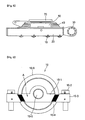
- the turn table 70 is mounted to a center portion of the main frame 50 and a vibration-proof rubber 70-1 is interposed between the turn table 70 and the main frame 50.
- An empty space 70-2 is provided under the turn table 70 and also serves to absorb a shock.
- the shock absorption bridge 40 is fixed to the roller frame 20 at its one side and to the main frame 50 at the other side thereof Referring to FIG 10 , the shock absorption bridge 40 has a stacked structure in which a plurality of vibration-proof rubber plates 40-2 for bridge and a plurality of steel plates 40-3 are alternately stacked. In the shock absorption bridge 40, steel plates 40-1 and 40-4 form the outermost plates and are coupled to the roller frame 20 and the main frame 50, respectively.
- Reference numeral 30 denotes a motor casing.
- FIG 6 and FIG 7 illustrate a front view and a right side view of the vibration-proof roller 10, respectively.
- the vibration-proof rollers 10 are installed between the beams 21.
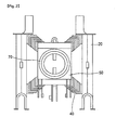
- each vibration-proof roller 10 includes a cylindrical roller body 10-6, a roller shaft 10-5 installed to pass through the center of the cylindrical roller body 10-6, collar units 10-1 installed on both sides of the roller shaft 10-5 and provided with dove-tails A at its end portions, nuts 10-3 for supporting the dove-tails A and fixing the vibration-proof roller 10, and bolts 10-2 associated with the vibration-proof roller through the nuts 10-3, respectively.
- a vibration-proof rubber 10-4 for a roller is interposed between the collar unit 10-1 and the nut 10-3 for absorbing a shock.
- the nut 10-3 has a sloped side corresponding to the dove-tail A.
- FIG 8 and FIG 9 illustrate a partial view of an undercarriage having a shock absorption function, according to another embodiment of the present invention, wherein FIG 8 is a front view and FIG 9 is a right side view.
- the undercarriage according to another embodiment of the present invention has a vibration-proof roller 11.
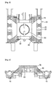
- the vibration-proof roller 11 includes a cylindrical roller body 11-4, collar units 11-1 attached to both sides, respectively, of the roller body 11-4, a roller shaft 11-5 installed to penetrate the center of the roller body 11-4 and the collar units 11-1, and position fixation units 11-2 attached to the both end portions, respectively of the roller shaft 11-5, each of the position fixation unit 11-2 having a vibration-proof rubber inside thereof
- the position fixation unit 11-2 has a hole to be mated with a bolt, so that the vibration-proof roller 11 to be coupled to the roller frame 20 by the bolt.
- the vibration-proof roller in the roller frame 20 primarily absorbs the shock or shake.
- the vibration-proof rollers There are two types of the vibration-proof rollers as described above.
- the vibration-proof rubber 11-3 attached to the position fixation unit 11-2 primarily absorbs a shock.
- the vibration-proof rubber plates 40-2 for bridge of the shock absorption bridge secondarily absorb the remaining of the shock. Since the shock absorption bridge 40 has a structure in which the vibration-proof rubber plates 40-2 for bridge and the steel plates 40-3 are alternately stacked, the shock is effectively absorbed by the shock absorption bridge 40.
- the vibration-proof rubber 70-1 for turn table, attached to under the turn table 70 finally absorbs the remaining of the shock. Further, due to the empty space 70-2 under the turn table 70, the shock is more effectively absorbed.
- the undercarriage according to the present invention has at least the following advantages.
Landscapes
- Engineering & Computer Science (AREA)
- Chemical & Material Sciences (AREA)
- Combustion & Propulsion (AREA)
- Transportation (AREA)
- Mechanical Engineering (AREA)
- Architecture (AREA)
- Structural Engineering (AREA)
- Vibration Prevention Devices (AREA)
- Body Structure For Vehicles (AREA)
- Vibration Dampers (AREA)
- Vehicle Body Suspensions (AREA)
Abstract
Description
- The present invention relates to an undercarriage used for construction equipment, and more particularly, to an undercarriage having a shock absorbing function which is implemented by a vibration-proof roller provided inside a roller frame instead of a conventional roller, and a shock absorbing bridge which serves to absorb a shock applied to the undercarriage and is fixed between a main frame and the roller frame, in which the undercarriage can enhance ride comfort of the construction equipment by minimizing an external shock.
- Generally, an undercarriage is a set of lower drive parts of construction equipment such as excavator for supporting an upper part of the construction equipment and is provided with a rubber track, an endless chain.
-
FIG 12 illustrates a perspective view of a conventional undercarriage andFIG 13 illustrates a right side view of a track roller attached to the conventional undercarriage. Referring toFIG 12 andFIG 13 , a main body of the undercarriage is integrated into a single body and is made of steel. - The conventional undercarriage has a plurality of track rollers (their mounted status is not shown in figures) disposed inside a
roller frame 20a in which each of the track rollers is enclosed by a conventional rubber track. - The
roller frame 20a and amain frame 50a are connected via abody bridge 40a. Themain frame 50a has a hole at the center portion thereof, and a turn table 70a is provided in the hole. - The conventional undercarriages are found in crawler-type vehicles such as construction equipment, and their structure is well known to people skilled in the related arts. Accordingly, detailed description on the structure of the conventional undercarriage will be omitted.
- The above conventional undercarriage does not have a shock absorber. Accordingly, in use of construction equipment such as an excavator provided with a steel endless track, a shock generated due to the condition of the surface of road and caused to the undercarriage is transferred to an operator of the excavator. For such reason, the excavator operator easily gets tired and operation efficiency of the excavator decreases.
- Reason of the foregoing is thought that the undercarriage can not absorb a shock generated due to the roughness of the surface of road and thus all of the shock is transferred to the operator since the undercarriage is made of steel and integrated into a single body. The conventional undercarriage has a further problem that the excavator employing the undercarriage has a short life span due to the external shock.
- The Japanese patent application
JP 04336129 A - The Japanese patent application
JP 04336128 A - Regarding the reduction of traveling vibrations of a crawler, the Japanese patent application
JP 2004-338532 A - The present invention, therefore, is provided to solve aforementioned problems and there is provided an undercarriage having a shock absorption function by employing a vibration-proof roller disposed inside a roller frame instead of a conventional roller and a shock absorbing bridge fixed between a main frame and the roller frame.
- In order to achieve such objects of the present invention, an undercarriage according to claim 1 is provided.
- The above and other features of the present invention will be described in reference to certain exemplary embodiments thereof with reference to the attached drawings in which:
-
FIG 1 is a perspective view illustrating an undercarriage having a shock absorption function, according to one embodiment of the present invention; -
FIG 2 is a plan view illustrating the undercarriage having a shock absorption function, according to one embodiment of the present invention; -
FIG 3 is a bottom view illustrating the undercarriage having a shock absorption function, according to one embodiment of the present invention; -
FIG 4 is a front view illustrating the undercarriage having a shock absorption function, according to one embodiment of the present invention; -
FIG 5 is a right side view illustrating the undercarriage having a shock absorption function, according to one embodiment of the present invention; -
FIG 6 is a front view illustrating a vibration-proof roller of the undercarriage having a shock absorption function, according to the present invention; -
FIG. 7 is a right side view illustrating the vibration-proof roller of the undercarriage having a shock absorption function, according to the present invention; -
FIG 8 is a front view illustrating a roller of an undercarriage having a shock absorption function, according to another embodiment of the present invention; -
FIG 9 is a right side view illustrating the roller of the undercarriage having a shock absorption function, according to another embodiment of the present invention; -
FIG 10 is a right side view illustrating an undercarriage bridge of the undercarriage having a shock absorption function, according to the one embodiment of the present invention; -
FIG 11 is a sectional view illustrating a turn table of the undercarriage having a shock absorption function, according to the one embodiment of the present invention; -
FIG 12 is a perspective view of a conventional undercarriage; and -
FIG 13 is a right side view illustrating a track roller to be attached to the conventional undercarriage. - The present invention will now be described more fully hereinafter with reference to the accompanying drawings, in which preferred embodiments of the invention are shown.
-
FIG 1 illustrates an undercarriage having a shock absorption function according to one embodiment of the present invention andFIGS. 2 to 5 are a plan view, a bottom view, a front view, and a right side view, respectively, of the undercarriage according to the one embodiment of the present invention. - Referring to
FIGS. 1 to 5 , the undercarriage according to the present invention includes a pair ofroller frames 20, amain frame 50 disposed between theroller frames 20 which are facing each other such that it is movable in the vertical direction and the horizontal direction, and ashock absorption bridge 40 extending across a space between themain frame 50 and theroller frame 20. - The undercarriage further includes a plurality of vibration-
proof rollers 10 installed inside a lower portion of theroller frame 20. - Hereinafter, each element constituting the undercarriage will be described in detail.
- A pair of
roller frames 20 comprises a pair ofbeams 21 which are facing each other and aconnection bar 22 fixed between thebeams 21. In eachroller frame 20, that is, between thebeams 21 of theroller frame 20, a plurality of vibration-proof rollers 10 is provided. The structure of the vibration-proof roller 10 will be described later. - The
main frame 50 is installed between theroller frames 20 such that it is movable in the vertical direction and the horizontal direction by theshock absorption bridge 40. Themain frame 50 has a dowserframe connection hole 60 and a high pressure hydraulic hose connection hole 50-1. - Referring to
FIG 11 , the turn table 70 is mounted to a center portion of themain frame 50 and a vibration-proof rubber 70-1 is interposed between the turn table 70 and themain frame 50. An empty space 70-2 is provided under the turn table 70 and also serves to absorb a shock. - The
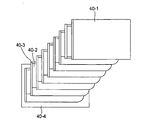
shock absorption bridge 40 is fixed to theroller frame 20 at its one side and to themain frame 50 at the other side thereof Referring toFIG 10 , theshock absorption bridge 40 has a stacked structure in which a plurality of vibration-proof rubber plates 40-2 for bridge and a plurality of steel plates 40-3 are alternately stacked. In theshock absorption bridge 40, steel plates 40-1 and 40-4 form the outermost plates and are coupled to theroller frame 20 and themain frame 50, respectively.Reference numeral 30 denotes a motor casing. -
FIG 6 andFIG 7 illustrate a front view and a right side view of the vibration-proof roller 10, respectively. The vibration-proof rollers 10 are installed between thebeams 21. Referring toFIGS. 6 and7 , each vibration-proof roller 10 includes a cylindrical roller body 10-6, a roller shaft 10-5 installed to pass through the center of the cylindrical roller body 10-6, collar units 10-1 installed on both sides of the roller shaft 10-5 and provided with dove-tails A at its end portions, nuts 10-3 for supporting the dove-tails A and fixing the vibration-proof roller 10, and bolts 10-2 associated with the vibration-proof roller through the nuts 10-3, respectively. A vibration-proof rubber 10-4 for a roller is interposed between the collar unit 10-1 and the nut 10-3 for absorbing a shock. The nut 10-3 has a sloped side corresponding to the dove-tail A. -
FIG 8 andFIG 9 illustrate a partial view of an undercarriage having a shock absorption function, according to another embodiment of the present invention, whereinFIG 8 is a front view andFIG 9 is a right side view. Referring toFIGS. 8 and9 , the undercarriage according to another embodiment of the present invention has a vibration-proof roller 11. The vibration-proof roller 11 includes a cylindrical roller body 11-4, collar units 11-1 attached to both sides, respectively, of the roller body 11-4, a roller shaft 11-5 installed to penetrate the center of the roller body 11-4 and the collar units 11-1, and position fixation units 11-2 attached to the both end portions, respectively of the roller shaft 11-5, each of the position fixation unit 11-2 having a vibration-proof rubber inside thereof On the other hand, the position fixation unit 11-2 has a hole to be mated with a bolt, so that the vibration-proof roller 11 to be coupled to theroller frame 20 by the bolt. - Hereinafter, the shock absorbing operation of the undercarriage will be described.
- In the case that a shock or a shake is caused to the undercarriage, the vibration-proof roller in the
roller frame 20 primarily absorbs the shock or shake. There are two types of the vibration-proof rollers as described above. - In case of using the vibration-
proof roller 10 shown inFIG 6 , a shake applied to the undercarriage in the vertical direction and the horizontal direction is absorbed by the vibration-proof rubber 10-4 for roller disposed between the dove-tail A and the nut 10-3. - In case of using the vibration-
proof roller 11 shown inFIG 8 , the vibration-proof rubber 11-3 attached to the position fixation unit 11-2 primarily absorbs a shock. Then, the vibration-proof rubber plates 40-2 for bridge of the shock absorption bridge secondarily absorb the remaining of the shock. Since theshock absorption bridge 40 has a structure in which the vibration-proof rubber plates 40-2 for bridge and the steel plates 40-3 are alternately stacked, the shock is effectively absorbed by theshock absorption bridge 40. Then, the vibration-proof rubber 70-1 for turn table, attached to under the turn table 70, finally absorbs the remaining of the shock. Further, due to the empty space 70-2 under the turn table 70, the shock is more effectively absorbed. - The undercarriage according to the present invention has at least the following advantages.
- First, it is possible to enhance operator's ride comfort, ensure stability of construction equipment and increase life span of construction equipment not only by absorbing a shock generated due to roughness of the surface of road when driving the construction equipment but also by inhibiting transfer of vibration generated from an upper part of the construction equipment during its operation to a lower part of the construction equipment.
- Second, it is possible to enhance operator's ride comfort with respect to construction equipment and enhance durability of construction equipment by alleviating stepwise a shock generated due to the roughness of the surface of road and bad operation condition of the construction equipment while operating the construction equipment having the undercarriage.
- Third, it is possible to enhance operation efficiency of construction equipment by enhancing operator's ride comfort of the construction equipment and enhancing durability of construction equipment by intercepting a shock to be transferred to a body of an excavator and alleviating vibration and noise.
- Although the present invention has been described with reference to certain exemplary embodiments thereof, it will be understood by those skilled in the art that a variety of modifications and variations may be made to the present invention without departing from the scope of the present invention defined in the appended claims, and their equivalents.
Claims (5)
- An undercarriage having a shock-absorption function, comprising:a pair of roller frames (20) facing each other;a main frame (50) disposed between the roller frames (20), and provided with a turn table (70) at a center portion thereof; anda shock absorption bridge (40) for connecting the main frame (50) to the roller frame (20),characterized in thatthe shock absorption bridge (40) has a stacked structure in which a plurality of vibration-proof rubber plates (40-2) for the bridge (40) and a plurality of steel plates (40-3) are alternately stacked, andeach roller frame (20) has a plurality of vibration-proof rollers (10) inside thereof, at a lower portion thereof.
- The undercarriage according to claim 1, wherein the vibration-proof roller (10) comprises:a cylindrical roller body (10-6);a roller shaft (10-5) installed to pass through a center portion of the roller body (10-6);a collar unit (10-1) disposed on both sides of the roller shaft (10-5) and processed to have dove-tails at its end portions;a nut (10-3) for supporting the dove-tails of the collar unit (10-1) and fixing the vibration-proof roller (10);a bolt (10-2) associated with the vibration-proof roller (10) through the nut (10-3); anda vibration-proof rubber (10-4) for the roller (20) interposed between the collar unit (10-1) and the nut (10-3).
- The undercarriage according to claim 1, wherein the vibration-proof roller (10) comprises:a cylinder roller body (11-4);a collar unit (11-1) attached to both sides of the roller body (11-4);a roller shaft (11-5) installed to penetrate the roller body (11-4) and the collar unit (11-1); anda position fixation unit (11-2) attached to both end portions of the roller shaft (11-5), having a vibration-proof rubber (11-3) at an inner side thereof
- The undercarriage according to claim 1, wherein the turn table (70) is installed at a center portion of the main frame (50) and a vibration-proof rubber (70-1) for the turn table (70) is interposed between the turn table (70) and the main frame (50).
- The undercarriage according to claim 1, wherein the shock absorption bridge (40) is fixed to the main frame (50) at one side thereof and to the roller frame (20) at the other side thereof such that the main frame (50) is movable in the vertical direction and the horizontal direction.
Applications Claiming Priority (1)
| Application Number | Priority Date | Filing Date | Title |
|---|---|---|---|
| KR1020050044559A KR100600337B1 (en) | 2005-05-26 | 2005-05-26 | Undercarriage with shock absorption |
Publications (3)
| Publication Number | Publication Date |
|---|---|
| EP1726515A2 EP1726515A2 (en) | 2006-11-29 |
| EP1726515A3 EP1726515A3 (en) | 2007-06-27 |
| EP1726515B1 true EP1726515B1 (en) | 2009-02-18 |
Family
ID=35735155
Family Applications (1)
| Application Number | Title | Priority Date | Filing Date |
|---|---|---|---|
| EP05027353A Expired - Lifetime EP1726515B1 (en) | 2005-05-26 | 2005-12-14 | Tracked vehicle with undercarriage having shock absorption function |
Country Status (7)
| Country | Link |
|---|---|
| US (1) | US7717201B2 (en) |
| EP (1) | EP1726515B1 (en) |
| JP (1) | JP4287426B2 (en) |
| KR (1) | KR100600337B1 (en) |
| CN (1) | CN100591870C (en) |
| AT (1) | ATE423056T1 (en) |
| DE (1) | DE602005012809D1 (en) |
Families Citing this family (15)
| Publication number | Priority date | Publication date | Assignee | Title |
|---|---|---|---|---|
| JP2005271602A (en) * | 2004-03-22 | 2005-10-06 | Komatsu Ltd | Construction machinery |
| KR101370194B1 (en) | 2007-11-30 | 2014-03-06 | 두산인프라코어 주식회사 | Movable track apparatus having suspension function |
| JP5821425B2 (en) * | 2011-08-31 | 2015-11-24 | マツダ株式会社 | Vehicle body structure |
| CN103171636A (en) * | 2011-12-22 | 2013-06-26 | 天津建筑机械厂 | Crawler-type running system of amphibious special vehicle |
| USD686252S1 (en) * | 2012-05-10 | 2013-07-16 | Hitachi Construction Machinery Co., Ltd. | Frame for a construction machine |
| CN103395454A (en) * | 2013-08-04 | 2013-11-20 | 贵州詹阳动力重工有限公司 | Caterpillar type all-terrain vehicle shock absorption chassis |
| CN104527826B (en) * | 2014-12-25 | 2016-08-17 | 浙江亿森机械有限公司 | A kind of upper lower bearing bracket shock-damping structure being applicable to light track tractor |
| KR101695257B1 (en) * | 2015-03-09 | 2017-01-12 | 한화테크윈 주식회사 | Housing Structure of Track-Type SUGV |
| CN105599815B (en) * | 2016-01-15 | 2019-04-30 | 江苏大学 | A profiling vibration-absorbing crawler-type walking chassis for a grain combine harvester |
| CN108327794B (en) * | 2018-03-14 | 2023-09-05 | 星光农机股份有限公司 | Tractor frame and travelling wheel system |
| CN108487350B (en) * | 2018-04-13 | 2023-11-21 | 新兴移山(天津)重工有限公司 | Mechanical bogie frame |
| CN109367635B (en) * | 2018-09-30 | 2020-07-14 | 湖南农夫机电有限公司 | Crawler tractor damper |
| USD931343S1 (en) * | 2019-06-26 | 2021-09-21 | J.C. Bamford Excavators Limited | Excavator undercarriage |
| EP4331955A4 (en) * | 2021-06-08 | 2024-11-06 | Kobelco Construction Machinery Co., Ltd. | UNDERCARRIAGE OF A MOBILE CRANE AND MOBILE CRANE EQUIPPED WITH IT |
| US12286174B2 (en) | 2021-09-16 | 2025-04-29 | Caterpillar Inc. | Roller mounting and roller block assemblies for ground-engaging track system |
Family Cites Families (31)
| Publication number | Priority date | Publication date | Assignee | Title |
|---|---|---|---|---|
| US1317650A (en) * | 1919-09-30 | Tractor truck mechanism | ||
| US2978050A (en) * | 1958-10-28 | 1961-04-04 | Caterpillar Tractor Co | Front end suspension for tractors |
| US3012624A (en) * | 1959-06-29 | 1961-12-12 | Gen Steel Ind Inc | Equalized crawler device |
| US3764184A (en) * | 1972-05-02 | 1973-10-09 | Allis Chalmers | Shock mounted track carrier roller |
| JPS6028873Y2 (en) * | 1980-10-06 | 1985-09-02 | セイレイ工業株式会社 | Stopper structure in engine vibration isolation structure |
| JPS5973648U (en) * | 1982-11-10 | 1984-05-18 | 株式会社ブリヂストン | air spring suspension system |
| US4501139A (en) * | 1983-08-26 | 1985-02-26 | Mts Systems Corporation | Test system for testing front wheel drive components of automobiles |
| US4733855A (en) * | 1986-12-22 | 1988-03-29 | Lord Corporation | Tapered rubber spring units |
| DE3720126A1 (en) * | 1987-06-16 | 1988-12-29 | Krauss Maffei Ag | Fighting vehicle on tracks - has turret in anti-vibration mountings in hull |
| EP0336627B1 (en) * | 1988-03-31 | 1994-08-03 | Dunlop Limited | Resilient mounting |
| JP2509636Y2 (en) * | 1990-01-23 | 1996-09-04 | 新キャタピラー三菱株式会社 | Elastic suspension for tracked vehicles |
| JPH0616160A (en) * | 1991-01-31 | 1994-01-25 | Komatsu Ltd | Link type suspension system |
| JPH04336128A (en) * | 1991-05-14 | 1992-11-24 | Sumitomo Constr Mach Co Ltd | Device for lower travelling body of construction machine |
| JPH04336129A (en) * | 1991-05-14 | 1992-11-24 | Sumitomo Constr Mach Co Ltd | Connecting device for lower travelling body and upper rotary body of construction machine |
| JPH05319323A (en) * | 1992-05-27 | 1993-12-03 | Yanmar Agricult Equip Co Ltd | Agricultural working vehicle |
| JPH0610078U (en) * | 1992-07-17 | 1994-02-08 | 新キャタピラー三菱株式会社 | Base frame structure for construction machinery |
| US5286044A (en) * | 1993-01-29 | 1994-02-15 | Caterpillar Inc. | Belted multi-purpose trailer |
| SE504773C2 (en) * | 1993-04-30 | 1997-04-21 | Josam Lastbilteknik Ab | Target unit for damaged vehicle bodies and vehicle chassis |
| JPH08105437A (en) * | 1994-10-05 | 1996-04-23 | Shin Caterpillar Mitsubishi Ltd | Vibration reducing swing bearing |
| JP2990590B2 (en) * | 1996-04-08 | 1999-12-13 | ヘンドリクソン・アジア株式会社 | Axle suspension |
| US5676356A (en) * | 1996-05-30 | 1997-10-14 | The Boler Company | Flexible bolster |
| JPH10157660A (en) * | 1996-11-27 | 1998-06-16 | Seirei Ind Co Ltd | Traveling farm work machine |
| US6170588B1 (en) * | 1997-06-03 | 2001-01-09 | Hitachi Construction Machinery Co., Ltd. | Revolving construction machine |
| CA2266791C (en) * | 1998-03-27 | 2005-02-01 | Manitowoc Crane Group, Inc. | Four track crawler crane |
| EP1035258B1 (en) * | 1998-06-15 | 2003-05-28 | Hitachi Construction Machinery Co., Ltd. | Construction machinery with cab |
| US6322104B1 (en) * | 1999-03-02 | 2001-11-27 | Clark Equipment Company | Excavator frame and method of assembly |
| JP3598089B2 (en) * | 2001-10-22 | 2004-12-08 | 住友ゴム工業株式会社 | Roller support structure of crawler traveling device |
| JP2004028302A (en) * | 2002-06-28 | 2004-01-29 | Bridgestone Corp | Layered rubber support and multi-stage type base isolation support device |
| JP2004338532A (en) * | 2003-05-15 | 2004-12-02 | Sumitomo Rubber Ind Ltd | Crawler traveling device |
| US7234723B2 (en) | 2003-06-27 | 2007-06-26 | E-Z Ride Corp. | Bolster spring suspension assembly |
| JP4490699B2 (en) * | 2004-02-12 | 2010-06-30 | ヤンマー株式会社 | Roller wheel of crawler type traveling device |
-
2005
- 2005-05-26 KR KR1020050044559A patent/KR100600337B1/en not_active Expired - Fee Related
- 2005-11-30 JP JP2005347158A patent/JP4287426B2/en not_active Expired - Fee Related
- 2005-12-06 US US11/296,096 patent/US7717201B2/en not_active Expired - Fee Related
- 2005-12-14 DE DE602005012809T patent/DE602005012809D1/en not_active Expired - Lifetime
- 2005-12-14 AT AT05027353T patent/ATE423056T1/en not_active IP Right Cessation
- 2005-12-14 EP EP05027353A patent/EP1726515B1/en not_active Expired - Lifetime
- 2005-12-29 CN CN200510135989A patent/CN100591870C/en not_active Expired - Fee Related
Also Published As
| Publication number | Publication date |
|---|---|
| KR100600337B1 (en) | 2006-07-18 |
| JP4287426B2 (en) | 2009-07-01 |
| CN100591870C (en) | 2010-02-24 |
| EP1726515A3 (en) | 2007-06-27 |
| US20060267304A1 (en) | 2006-11-30 |
| ATE423056T1 (en) | 2009-03-15 |
| US7717201B2 (en) | 2010-05-18 |
| JP2006327567A (en) | 2006-12-07 |
| EP1726515A2 (en) | 2006-11-29 |
| CN1869343A (en) | 2006-11-29 |
| DE602005012809D1 (en) | 2009-04-02 |
Similar Documents
| Publication | Publication Date | Title |
|---|---|---|
| EP1726515A2 (en) | Tracked vehicle with undercarriage having shock absorption function | |
| EP2441652B1 (en) | Apparatus for controlling tension of track | |
| US7231993B2 (en) | Drive track support with vibration isolation | |
| JP2004099017A (en) | Front wheel suspension device utilizing steering gear frame | |
| KR20210158733A (en) | Undercarriage with shock absorption function that blocks transmission of shock loads transmitted to the body of an excavator and reduces vibration and noise | |
| US20030122423A1 (en) | High stiffness track assembly for undercarriage noise reduction | |
| JPH09136676A (en) | Crawler and crawler car | |
| KR20190091850A (en) | Battery Mounting Structure in Electric Vehicle of Frame Type with aluminium material | |
| JP3675927B2 (en) | Frame structure of traveling vehicle | |
| EP1454817B1 (en) | Motor-vehicle having an anti-noise frame carrying the engine and suspension units | |
| CN223721036U (en) | Chassis driving device of crawler-type all-terrain vehicle | |
| CN221874178U (en) | Vehicle with triangular crawler belt damping device | |
| JP4297332B2 (en) | Crawler track | |
| KR100828762B1 (en) | Leaf Spring Suspension in Front Two-Axis Vehicles | |
| JPH03193573A (en) | Intermediate roller supporting device for tractor, etc. | |
| KR200300862Y1 (en) | Asistance buffer equipment have a suspension system of trailer | |
| JPH11343637A (en) | Rotary crawler carrier | |
| JP4276518B2 (en) | Subframe mounting structure | |
| CN211592324U (en) | Tractor chassis with shock-absorbing function | |
| KR100506656B1 (en) | multileaf spring | |
| KR20020048489A (en) | body mounting structure of vehicle | |
| JP3165308B2 (en) | Traveling vehicle | |
| JP2001113928A (en) | Wheel type multi-purpose work vehicle | |
| JPH10230848A (en) | Railcar bogie | |
| JP4014170B2 (en) | Vehicle engine mounting device |
Legal Events
| Date | Code | Title | Description |
|---|---|---|---|
| PUAI | Public reference made under article 153(3) epc to a published international application that has entered the european phase |
Free format text: ORIGINAL CODE: 0009012 |
|
| 17P | Request for examination filed |
Effective date: 20051214 |
|
| AK | Designated contracting states |
Kind code of ref document: A2 Designated state(s): AT BE BG CH CY CZ DE DK EE ES FI FR GB GR HU IE IS IT LI LT LU LV MC NL PL PT RO SE SI SK TR |
|
| AX | Request for extension of the european patent |
Extension state: AL BA HR MK YU |
|
| PUAL | Search report despatched |
Free format text: ORIGINAL CODE: 0009013 |
|
| AK | Designated contracting states |
Kind code of ref document: A3 Designated state(s): AT BE BG CH CY CZ DE DK EE ES FI FR GB GR HU IE IS IT LI LT LU LV MC NL PL PT RO SE SI SK TR |
|
| AX | Request for extension of the european patent |
Extension state: AL BA HR MK YU |
|
| 17Q | First examination report despatched |
Effective date: 20070919 |
|
| AKX | Designation fees paid |
Designated state(s): AT BE BG CH CY CZ DE DK EE ES FI FR GB GR HU IE IS IT LI LT LU LV MC NL PL PT RO SE SI SK TR |
|
| GRAP | Despatch of communication of intention to grant a patent |
Free format text: ORIGINAL CODE: EPIDOSNIGR1 |
|
| GRAS | Grant fee paid |
Free format text: ORIGINAL CODE: EPIDOSNIGR3 |
|
| GRAA | (expected) grant |
Free format text: ORIGINAL CODE: 0009210 |
|
| AK | Designated contracting states |
Kind code of ref document: B1 Designated state(s): AT BE BG CH CY CZ DE DK EE ES FI FR GB GR HU IE IS IT LI LT LU LV MC NL PL PT RO SE SI SK TR |
|
| REG | Reference to a national code |
Ref country code: GB Ref legal event code: FG4D |
|
| REG | Reference to a national code |
Ref country code: CH Ref legal event code: EP |
|
| REG | Reference to a national code |
Ref country code: IE Ref legal event code: FG4D |
|
| REF | Corresponds to: |
Ref document number: 602005012809 Country of ref document: DE Date of ref document: 20090402 Kind code of ref document: P |
|
| PG25 | Lapsed in a contracting state [announced via postgrant information from national office to epo] |
Ref country code: NL Free format text: LAPSE BECAUSE OF FAILURE TO SUBMIT A TRANSLATION OF THE DESCRIPTION OR TO PAY THE FEE WITHIN THE PRESCRIBED TIME-LIMIT Effective date: 20090218 Ref country code: SI Free format text: LAPSE BECAUSE OF FAILURE TO SUBMIT A TRANSLATION OF THE DESCRIPTION OR TO PAY THE FEE WITHIN THE PRESCRIBED TIME-LIMIT Effective date: 20090218 Ref country code: ES Free format text: LAPSE BECAUSE OF FAILURE TO SUBMIT A TRANSLATION OF THE DESCRIPTION OR TO PAY THE FEE WITHIN THE PRESCRIBED TIME-LIMIT Effective date: 20090529 Ref country code: LT Free format text: LAPSE BECAUSE OF FAILURE TO SUBMIT A TRANSLATION OF THE DESCRIPTION OR TO PAY THE FEE WITHIN THE PRESCRIBED TIME-LIMIT Effective date: 20090218 Ref country code: FI Free format text: LAPSE BECAUSE OF FAILURE TO SUBMIT A TRANSLATION OF THE DESCRIPTION OR TO PAY THE FEE WITHIN THE PRESCRIBED TIME-LIMIT Effective date: 20090218 |
|
| NLV1 | Nl: lapsed or annulled due to failure to fulfill the requirements of art. 29p and 29m of the patents act | ||
| PG25 | Lapsed in a contracting state [announced via postgrant information from national office to epo] |
Ref country code: SE Free format text: LAPSE BECAUSE OF FAILURE TO SUBMIT A TRANSLATION OF THE DESCRIPTION OR TO PAY THE FEE WITHIN THE PRESCRIBED TIME-LIMIT Effective date: 20090518 Ref country code: LV Free format text: LAPSE BECAUSE OF FAILURE TO SUBMIT A TRANSLATION OF THE DESCRIPTION OR TO PAY THE FEE WITHIN THE PRESCRIBED TIME-LIMIT Effective date: 20090218 Ref country code: PL Free format text: LAPSE BECAUSE OF FAILURE TO SUBMIT A TRANSLATION OF THE DESCRIPTION OR TO PAY THE FEE WITHIN THE PRESCRIBED TIME-LIMIT Effective date: 20090218 Ref country code: IS Free format text: LAPSE BECAUSE OF FAILURE TO SUBMIT A TRANSLATION OF THE DESCRIPTION OR TO PAY THE FEE WITHIN THE PRESCRIBED TIME-LIMIT Effective date: 20090618 Ref country code: AT Free format text: LAPSE BECAUSE OF FAILURE TO SUBMIT A TRANSLATION OF THE DESCRIPTION OR TO PAY THE FEE WITHIN THE PRESCRIBED TIME-LIMIT Effective date: 20090218 |
|
| PG25 | Lapsed in a contracting state [announced via postgrant information from national office to epo] |
Ref country code: BE Free format text: LAPSE BECAUSE OF FAILURE TO SUBMIT A TRANSLATION OF THE DESCRIPTION OR TO PAY THE FEE WITHIN THE PRESCRIBED TIME-LIMIT Effective date: 20090218 |
|
| PG25 | Lapsed in a contracting state [announced via postgrant information from national office to epo] |
Ref country code: CZ Free format text: LAPSE BECAUSE OF FAILURE TO SUBMIT A TRANSLATION OF THE DESCRIPTION OR TO PAY THE FEE WITHIN THE PRESCRIBED TIME-LIMIT Effective date: 20090218 Ref country code: DK Free format text: LAPSE BECAUSE OF FAILURE TO SUBMIT A TRANSLATION OF THE DESCRIPTION OR TO PAY THE FEE WITHIN THE PRESCRIBED TIME-LIMIT Effective date: 20090218 Ref country code: EE Free format text: LAPSE BECAUSE OF FAILURE TO SUBMIT A TRANSLATION OF THE DESCRIPTION OR TO PAY THE FEE WITHIN THE PRESCRIBED TIME-LIMIT Effective date: 20090218 Ref country code: PT Free format text: LAPSE BECAUSE OF FAILURE TO SUBMIT A TRANSLATION OF THE DESCRIPTION OR TO PAY THE FEE WITHIN THE PRESCRIBED TIME-LIMIT Effective date: 20090727 |
|
| PG25 | Lapsed in a contracting state [announced via postgrant information from national office to epo] |
Ref country code: RO Free format text: LAPSE BECAUSE OF FAILURE TO SUBMIT A TRANSLATION OF THE DESCRIPTION OR TO PAY THE FEE WITHIN THE PRESCRIBED TIME-LIMIT Effective date: 20090218 Ref country code: SK Free format text: LAPSE BECAUSE OF FAILURE TO SUBMIT A TRANSLATION OF THE DESCRIPTION OR TO PAY THE FEE WITHIN THE PRESCRIBED TIME-LIMIT Effective date: 20090218 |
|
| PLBE | No opposition filed within time limit |
Free format text: ORIGINAL CODE: 0009261 |
|
| STAA | Information on the status of an ep patent application or granted ep patent |
Free format text: STATUS: NO OPPOSITION FILED WITHIN TIME LIMIT |
|
| 26N | No opposition filed |
Effective date: 20091119 |
|
| PG25 | Lapsed in a contracting state [announced via postgrant information from national office to epo] |
Ref country code: BG Free format text: LAPSE BECAUSE OF FAILURE TO SUBMIT A TRANSLATION OF THE DESCRIPTION OR TO PAY THE FEE WITHIN THE PRESCRIBED TIME-LIMIT Effective date: 20090518 |
|
| PG25 | Lapsed in a contracting state [announced via postgrant information from national office to epo] |
Ref country code: MC Free format text: LAPSE BECAUSE OF NON-PAYMENT OF DUE FEES Effective date: 20100701 |
|
| REG | Reference to a national code |
Ref country code: CH Ref legal event code: PL |
|
| GBPC | Gb: european patent ceased through non-payment of renewal fee |
Effective date: 20091214 |
|
| REG | Reference to a national code |
Ref country code: FR Ref legal event code: ST Effective date: 20100831 |
|
| REG | Reference to a national code |
Ref country code: IE Ref legal event code: MM4A |
|
| PG25 | Lapsed in a contracting state [announced via postgrant information from national office to epo] |
Ref country code: LI Free format text: LAPSE BECAUSE OF NON-PAYMENT OF DUE FEES Effective date: 20091231 Ref country code: IE Free format text: LAPSE BECAUSE OF NON-PAYMENT OF DUE FEES Effective date: 20091214 Ref country code: GR Free format text: LAPSE BECAUSE OF FAILURE TO SUBMIT A TRANSLATION OF THE DESCRIPTION OR TO PAY THE FEE WITHIN THE PRESCRIBED TIME-LIMIT Effective date: 20090519 Ref country code: FR Free format text: LAPSE BECAUSE OF NON-PAYMENT OF DUE FEES Effective date: 20091231 Ref country code: CH Free format text: LAPSE BECAUSE OF NON-PAYMENT OF DUE FEES Effective date: 20091231 |
|
| PG25 | Lapsed in a contracting state [announced via postgrant information from national office to epo] |
Ref country code: GB Free format text: LAPSE BECAUSE OF NON-PAYMENT OF DUE FEES Effective date: 20091214 |
|
| PG25 | Lapsed in a contracting state [announced via postgrant information from national office to epo] |
Ref country code: IT Free format text: LAPSE BECAUSE OF FAILURE TO SUBMIT A TRANSLATION OF THE DESCRIPTION OR TO PAY THE FEE WITHIN THE PRESCRIBED TIME-LIMIT Effective date: 20090218 |
|
| PG25 | Lapsed in a contracting state [announced via postgrant information from national office to epo] |
Ref country code: LU Free format text: LAPSE BECAUSE OF NON-PAYMENT OF DUE FEES Effective date: 20091214 |
|
| PG25 | Lapsed in a contracting state [announced via postgrant information from national office to epo] |
Ref country code: HU Free format text: LAPSE BECAUSE OF FAILURE TO SUBMIT A TRANSLATION OF THE DESCRIPTION OR TO PAY THE FEE WITHIN THE PRESCRIBED TIME-LIMIT Effective date: 20090819 |
|
| PG25 | Lapsed in a contracting state [announced via postgrant information from national office to epo] |
Ref country code: TR Free format text: LAPSE BECAUSE OF FAILURE TO SUBMIT A TRANSLATION OF THE DESCRIPTION OR TO PAY THE FEE WITHIN THE PRESCRIBED TIME-LIMIT Effective date: 20090218 |
|
| PG25 | Lapsed in a contracting state [announced via postgrant information from national office to epo] |
Ref country code: CY Free format text: LAPSE BECAUSE OF FAILURE TO SUBMIT A TRANSLATION OF THE DESCRIPTION OR TO PAY THE FEE WITHIN THE PRESCRIBED TIME-LIMIT Effective date: 20090218 |
|
| REG | Reference to a national code |
Ref country code: DE Ref legal event code: R082 Ref document number: 602005012809 Country of ref document: DE Representative=s name: GRUENECKER PATENT- UND RECHTSANWAELTE PARTG MB, DE Ref country code: DE Ref legal event code: R081 Ref document number: 602005012809 Country of ref document: DE Owner name: DRB HOLDING CO., LTD, KR Free format text: FORMER OWNER: DONG-IL RUBBER BELT CO., LTD., BUSAN, KR |
|
| PGFP | Annual fee paid to national office [announced via postgrant information from national office to epo] |
Ref country code: DE Payment date: 20171220 Year of fee payment: 13 |
|
| REG | Reference to a national code |
Ref country code: DE Ref legal event code: R119 Ref document number: 602005012809 Country of ref document: DE |
|
| PG25 | Lapsed in a contracting state [announced via postgrant information from national office to epo] |
Ref country code: DE Free format text: LAPSE BECAUSE OF NON-PAYMENT OF DUE FEES Effective date: 20190702 |