EP1726249A1 - Endoscope balloon control device - Google Patents
Endoscope balloon control device Download PDFInfo
- Publication number
- EP1726249A1 EP1726249A1 EP05720791A EP05720791A EP1726249A1 EP 1726249 A1 EP1726249 A1 EP 1726249A1 EP 05720791 A EP05720791 A EP 05720791A EP 05720791 A EP05720791 A EP 05720791A EP 1726249 A1 EP1726249 A1 EP 1726249A1
- Authority
- EP
- European Patent Office
- Prior art keywords
- balloon
- endoscope
- control device
- gas
- control unit
- Prior art date
- Legal status (The legal status is an assumption and is not a legal conclusion. Google has not performed a legal analysis and makes no representation as to the accuracy of the status listed.)
- Withdrawn
Links
Images





Classifications
-
- A—HUMAN NECESSITIES
- A61—MEDICAL OR VETERINARY SCIENCE; HYGIENE
- A61B—DIAGNOSIS; SURGERY; IDENTIFICATION
- A61B1/00—Instruments for performing medical examinations of the interior of cavities or tubes of the body by visual or photographical inspection, e.g. endoscopes; Illuminating arrangements therefor
-
- A—HUMAN NECESSITIES
- A61—MEDICAL OR VETERINARY SCIENCE; HYGIENE
- A61B—DIAGNOSIS; SURGERY; IDENTIFICATION
- A61B1/00—Instruments for performing medical examinations of the interior of cavities or tubes of the body by visual or photographical inspection, e.g. endoscopes; Illuminating arrangements therefor
- A61B1/31—Instruments for performing medical examinations of the interior of cavities or tubes of the body by visual or photographical inspection, e.g. endoscopes; Illuminating arrangements therefor for the rectum, e.g. proctoscopes or sigmoidoscopes
-
- A—HUMAN NECESSITIES
- A61—MEDICAL OR VETERINARY SCIENCE; HYGIENE
- A61B—DIAGNOSIS; SURGERY; IDENTIFICATION
- A61B1/00—Instruments for performing medical examinations of the interior of cavities or tubes of the body by visual or photographical inspection, e.g. endoscopes; Illuminating arrangements therefor
- A61B1/00064—Constructional details of the endoscope body
- A61B1/00071—Insertion part of the endoscope body
- A61B1/0008—Insertion part of the endoscope body characterised by distal tip features
- A61B1/00082—Balloons
-
- A—HUMAN NECESSITIES
- A61—MEDICAL OR VETERINARY SCIENCE; HYGIENE
- A61B—DIAGNOSIS; SURGERY; IDENTIFICATION
- A61B1/00—Instruments for performing medical examinations of the interior of cavities or tubes of the body by visual or photographical inspection, e.g. endoscopes; Illuminating arrangements therefor
- A61B1/00131—Accessories for endoscopes
- A61B1/00135—Oversleeves mounted on the endoscope prior to insertion
-
- A—HUMAN NECESSITIES
- A61—MEDICAL OR VETERINARY SCIENCE; HYGIENE
- A61B—DIAGNOSIS; SURGERY; IDENTIFICATION
- A61B1/00—Instruments for performing medical examinations of the interior of cavities or tubes of the body by visual or photographical inspection, e.g. endoscopes; Illuminating arrangements therefor
- A61B1/00147—Holding or positioning arrangements
- A61B1/00154—Holding or positioning arrangements using guiding arrangements for insertion
-
- A—HUMAN NECESSITIES
- A61—MEDICAL OR VETERINARY SCIENCE; HYGIENE
- A61B—DIAGNOSIS; SURGERY; IDENTIFICATION
- A61B1/00—Instruments for performing medical examinations of the interior of cavities or tubes of the body by visual or photographical inspection, e.g. endoscopes; Illuminating arrangements therefor
- A61B1/012—Instruments for performing medical examinations of the interior of cavities or tubes of the body by visual or photographical inspection, e.g. endoscopes; Illuminating arrangements therefor characterised by internal passages or accessories therefor
- A61B1/015—Control of fluid supply or evacuation
Definitions
- the present invention relates to an endoscope balloon control device, and relates to an endoscope balloon control device which can control pressures inside a balloon provided for a tip peripheral part of an inserting unit of an endoscope and a balloon provided for a tip peripheral part of an inserting unit of an overtube.
- endosocpy has been widely used in an alimentary canal examination.
- a deep alimentary canal such as the small intestine in such an endoscope examination
- the tip of the inserting unit is also drawn and the bending and the slack is not picked up, which makes the deep insertion difficult.
- An endoscope device adapted to prevent the tip of the inserting unit from being drawn when extra bending or slack of the endoscope is picked up by attaching a balloon to the tip peripheral part of the inserting unit of the endoscope and blowing up the balloon and temporally fixing it to the intestines are proposed.
- an endoscope device which can improve operational performance of the endoscope device by providing an overtube through which the inserting unit of the endoscope is inserted and attaching a balloon at the tip peripheral part of the overtube and blowing up or deflating the balloon of the overtube and the balloon of the endoscope as required is proposed.
- the Japanese Patent Laid-Open No. 2002-301019 discloses an endoscope device adapted to supply air from a pump device, while control means measures an air pressure inside each of the balloon of the endoscope and the balloon of the overtube and controls a pressure inside each of the balloons.
- the balloon of the endoscope and the balloon of the overtube are different from each other or if material of a ballo on differs for each time the balloon is exchanged, the balloon blows up different ways even with the same amount of flow. Therefore, in order to keep a constant way of blowing up even if the materials and the type of the balloons are different, the amount of flow of gas sent to each of the balloons needs to be controlled according to the material of the balloon. In order to control the amount of flow of gas sent or a gas sending pressure to each of the balloons, a gas sending time to each of the balloons needs to be measured.
- the present invention is adapted in view of the circumstances, and it is an object of the invention to provide an endoscope balloon control device which can measure a gas sending time or a gas drawing time to or from a balloon of an endoscope and a balloon of an overtube.
- the endoscope balloon control device of the present invention comprises: a pump for supplying or discharging gas to or from a balloon for fixing attached to a peripheral part of a tip part of an inserting unit of an endoscope; a time detecting unit for detecting a gas sending time or a gas drawing time to or from the balloon; and a control unit for controlling a pressure inside the balloon by measuring the gas pressure inside the balloon and operating the pump based on the measured result, and also controlling a pressure inside the balloon based on the detected result by the time detecting unit.
- Figure 1 is a configuration diagram showing an entire configuration of an endoscope system applied with an endoscope balloon control device according to a first embodiment of the present invention.
- an endoscope system 1 having an endoscope balloon control device of the embodiment has an endoscope 2, an overtube 3, a light source device 4, a video processor 5, a monitor 6, an endoscope balloon control device 7 and a remote controller 8.
- the endoscope 2 is used for an alimentary canal endoscope examination, for example, having an inserting unit 2B to be inserted in a body cavity and an operation unit 2A provided at a base end side of the inserting unit 2B.
- An observation optical system including an illumination optical system and a CCD which is an image pickup device (not shown) is provided in the tip part of the inserting unit 2B and illuminates an observed part in the alimentary canal of a subject body and can obtain an observation image in the alimentary canal of the subject body.
- a universal code 2C is extending out from the operation unit 2A. Inside the universal code 2C, a signal line and a light guide cable (not shown) are provided. The base end part of the universal code 2C is connected to a connector 4a of the light source device 4 and a connector 5a of the video processor 5. Accordingly, illumination light from the light source device 4 is supplied to the illumination optical system of the endoscope 2 via the light guide cable in the universal code 2C and illuminates the observed part, and outputs an image pick up signal in the alimentary canal outputted from the CCD to the video processor 5.
- Such an endoscope 2 is adapted to be used inserted through the overtube 3 during an operation.
- a configuration of the overtube 3 will be described later.
- the light source device 4 is a light source device for supplying illumination light to the illumination optical system provided for the endoscope 2 via a light guide (not shown) in the light guide cable.
- the video processor 5 performs signal processing on an image pickup signal from the CCD of the endoscope 2 and supplies image data based on the image pickup signal (for example, endoscope live image data) to the monitor 6.
- the monitor 6 is connected to the video processor 5 by a connecting cable 5A.
- the monitor 6 displays an endoscope image based on image data from the video processor 5.
- a fixing balloon 9 is attached to the tip peripheral part of the inserting unit 2B of the endoscope 2.
- An air supplying tube 10 provided along the inserting unit 2B from the base end part side to the tip part side of the inserting unit 2B is connected to the balloon 9.
- the base end part of the operation unit 2A of the air supplying tube 10 is connected to the connector 2a provided at the bottom of the operation unit 2A.
- a connector 13A which is provided at one end of an endoscope balloon gas sending tube (hereinafter, referred to as the first gas sending tube) 13, the other end of which is connected to an endoscope balloon control device 7 to be described later.
- the balloon 9 is blown up by gas sent from the endoscope balloon control device 7 and temporally fixed to the alimentary canal such as the intestinal canal.
- the overtube 3 is for guiding the inserting unit 2B to be inserted in the alimentary canal, for example, by inserting the endoscope 2 through it, and has a little bit bigger inside diameter than the external diameter of the inserting unit 2B of the endoscope.
- the overtube 3 has a configuration with the same flexibility as the inserting unit 2B of the endoscope 2. Further, to the tip peripheral part of the overtube 3, a tube fixing balloon 11 is attached.
- an air supplying tube 12 provided for the overtube 3 from its base end part side to its tip part side is connected.
- the base end part at the opposite side of the balloon 11 of the air supplying tube 12 (an inserting slot side for inserting the endoscope 2 of the overtube 3) is connected to a connector 3a provided near the inserting slot of the overtube 3.
- a connector 14A which is provided at one end of an overtube balloon gas sending tube (hereinafter referred to as a second gas sending tube) 14, the other end of which is connected to the endoscope balloon control device 7.
- the endoscope balloon control device 7 is for controlling various operations on the amount of flow of gas sent of the balloon 9 of the endoscope 2 and the balloon 11 of the overtube 3 and the like.
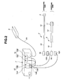
- Figure 2 is a configuration diagram showing an outlined configuration of the endoscope balloon control device.
- a backflow prevention tank 15 is provided for the endoscope balloon control device 7, and a pressure display device 16 and a power source switch 17 are provided at the front side of the device 7.
- the backflow prevention tank 15 is adapted to be able to prevent backflow of a liquid, having a tank 15A for the balloon 9 of the endoscope 2 and a tank 15B for the balloon 11 of the overtube 3.
- the first and the second gas sending tubes 13 and 14 are connected to the corresponding tanks 15A and 15B respectively.
- the tanks 15A and 15B send gas to the balloons 9 and 11 respectively via the first and the second gas sending tubes 13 and 14 by increasing the inside pressure via the first and the second pumps 32a and 32b (see Figure 4) to be described later by the control of the endoscope balloon control device 7, respectively.
- the tanks 15A and 15B are adapted to prevent backflow of a liquid from the first and the second gas sending tubes 13 and 14 by a backflow prevention mechanism (not shown).
- a gas sending duct via the air supplying tube 10 connected to the balloon 9 of the endoscope 2, the first gas sending tube 13, and the tank 15A, a gas sending duct via the air supplying tube 12 connected to the balloon 11 of the overtube 3, the second gas sending tube 14, and the tank 15B are provided for the endoscope balloon control device 7 of the embodiment.
- the pressure display device 16 is for displaying a pressure value of ducts connected to the balloons 9 and 11 by using a detecting device (not shown).
- the pressure display device 16 has a display device 16A for the balloon 9 of the endoscope 2 and a display device 16B for the balloon 11 of the overtube 3.
- the display device 16A displays a pressure value inside the duct for the balloon 9 of the endoscope 2, and the display device 16B displays a pressure value inside the duct for the balloon 11 of the overtube 3.
- the power source switch 17 is a switch for switching the power source of the endoscope balloon control device 7 between ON and OFF.
- the remote controller 8 is connected to a side of the endoscope balloon control device 7 via a connecting cable 8A.
- the remote controller 8 is electrically connected to a control unit 35 provide d inside the endoscope balloon control device 7 to be described later via the connecting cable 8A.
- the endoscope balloon control device 7 is adapted to be supplied with an operation signal for pressure control and gas sending control of each of the balloons 9 and 11 by an operator to manipulate the remote controller 8 during an operation.
- Figure 3 is a diagram showing a configuration example of the remote controller 8.
- the remote controller 8 is set up as its various buttons for controlling an endoscope side balloon and various buttons for controlling an overtube side balloon are divided into right and left of the main body of the remote controller, for example, for facilitating manipulation of the operator.
- a release button 18a At the left side of the remote controller 8, a release button 18a, a gas sending start button 19a, a gas drawing start button 20a and a stop button 21a are provided as operation buttons for controlling the endoscope side balloon.
- a release button 18b To the right side of the remote controller 8, a release button 18b, a gas sending start button 19b, a gas drawing button 20b and a stop button 21b are provided as operation buttons for controlling the overtube side balloon.
- a power source button 22, and an emergency stop button 23 are provided at the bottom of the remote controller 8.
- the release button 18a is a button for indicating to release air in a duct of the balloon 9 of the endoscope 2.
- the gas sending start button 19a is a button for indicting to start sending gas into the balloon 9 of the endoscope 2.
- the gas drawing start button 20a is a button for indicating to start drawing gas from the balloon 9 of the endoscope 2.
- the stop button 21a is a button for performing indication to stop a gas sending operation by the gas sending start button 19a or a gas drawing operation by the gas drawing start button 20a. As the stop button 21a is pressed down, an air pressure inside the balloon 9 can be kept.
- the release button 18b is a button for indicating to release air inside the duct of the balloon 11 of the overtube 3.
- the gas sending start button 19b is a button for indicating to start sending gas into the balloon 11 of the overtube 3.
- the gas drawing start button 20b is a button for indicating to start drawing gas from the balloon 11 of the overtube 3.
- the stop button 21b is a button for performing indication to stop a gas sending operation by the gas sending start button 19b and a gas drawing operation by the gas drawing start button 20b. As the stop button 21b is pressed down, an air pressure inside the balloon 11 or a duct can be kept.
- the power source switch 22 is a button for switching the power source of the endoscope balloon control device 7 between the ON state and the OFF state.
- the emergency stop button 23 is a button for directly turning off the first to the third breaker 31a to 31c to be described later of the endoscope balloon control device 7 and perform emergency stop on gas sending control of each of the balloons 9 and 11 by the endoscope balloon control device 7.
- Figure 4 is a block diagram showing an inner configuration of the endoscope balloon control device.
- the endoscope balloon control device 7 has a switching power source unit 30, a first to a third breakers 31a to 31c, a first and a second pumps 32a, 32b, a first and a second amount of flow adjustment valves 32c, 32d, a duct switching unit 33, a first and a second pressure sensors 34a, 34b, and a control unit 35 which is the control means.
- the switching power source unit 30 converts the supplied AC power into DC power and supplies it to the first to the third breakers 31a to 31c, the first and the second pressure sensors 34a and 34b, the control unit 35 and the emergency stop button 23 of the remote controller 8.
- the first breaker 31a is electrically connected to the first and the second pumps 32a and 32b and the emergency stop button 23 of the remote controller 8.
- the first breaker 31a supplies DC power to the first and the second pumps 32a and 32b. If an operation signal is supplied from the emergency stop button 23, supplying of DC power to the first and the second pumps 32a and 32b is stopped.
- the second breaker 31b is electrically connected to the duct switching unit 33 and the emergency stop button 23 of the remote controller 8.
- the second breaker 31b supplies DC power to the duct switching unit 33. If an operation signal is supplied from the emergency stop button 23, supplying of DC power to the duct switching unit 33 is stopped.
- the third breaker 31c is electrically connected to the first and the second amount of flow adjustment valves 32c and 32d and the emergency stop button 23 of the remote controller 8.
- the third breaker 31c supplies DC power to the first and the second amount of flow adjustment valves 32c and 32d. If an operation signal is supplied from the emergency stop button 23, supplying of DC power to the first and the second amount of flow adjustment valves 32c and 32d is stopped.
- the first and the second pumps 32a and 32b are connected to an input side of the duct switching unit 33 via an air line, respectively.
- the first and the second pumps 32a and 32b are adapted to be controlled for driving based on a control signal from the control unit 35. For example, they are adapted to s end air to the duct switching unit 33 via the air line, or, on the contrary, to draw air from the duct switching unit 33 via the air line.
- the first and the second amount of flow adjustment valves 32c and 32d are connected via an air line, respectively.
- the first and the second amount of flow adjustment valves 32c and 32d are valves which can be adjusted between open and close by the control unit 35, and makes adjustment of the amount of flow of air to be output based on a control signal from the control unit 35.
- the first and the second amount of flow adjustment valves 32c and 32d supply air by the adjusted amount flow within a predetermined range to the first and the second pressure sensors 34a and 34b via a gas sending line, respectively.
- the fist and second pressure sensors 34a and 34b measure air pressures supplied from the first and the second amount of flow adjustment valves 32c and 32d.
- measured results by the first and the second pressure sensors 34a and 35b may be supplied to the control unit 35 and the control unit 35 may be adapted to control the first and the second pumps 32a and 32b to make them desired air pressures based on the supplied measured results respectively.
- Outputs from the first and the second pressure sensors 34a and 34b are adapted to be supplied to the first and the second gas sending tubes 13 and 14 via a gas sending line, connectors 7A, 7B, 13B and 14B, respectively.
- the endoscope balloon control device 7 has a gas sending duct comprising the first amount of flow adjustment valve 32c and the first pressure sensor 34a via the fist pump 32a and the duct switching unit 33, and a gas sending duct comprising the second amount of flow adjustment valve 32d and the second pressure sensor 34b via the second pump 32b and the duct switching unit 33.
- the duct switching unit 33 can switch ducts (not shown) provided inside so as to make it a duct state according to an executing mode in the endoscope balloon control device 7.
- the executing mode there are four executing modes such as a gas sending mode, a gas drawing mode, a keeping mode, and a releasing mode. Therefore, the duct switching unit 33 can switch an inner duct (not shown) to make it a state according to the four modes, i.e., a gas sending state, a gas drawing state, a keeping state, and a releasing state.
- the switching can be controlled based on a control signal from the control unit 35.
- it is adapted to make the duct at the balloon 9 side of the endoscope 2 and the duct at the balloon 11 side of the overtube side 3 connected to the back side duct states based on respective desired executing modes.
- control unit 35 has an amount of flow counter for counting the amount of flow of gas sent to the balloon 9 of the endoscope 2 and the balloon 11 of the overtube 3; a timer counter, which is the gas sending time detecting means for counting each of a gas sending time and a gas drawing time of the balloons 9 and 11 or a timer for measuring a predetermined time; and a storing unit storing a main program to be described later or a program based on various modules.
- the control unit 35 is adapted to control the first and the second pumps 32a and 32b, and the duct switching unit 33 and the first and the second amount of flow adjustment valves 32c, 32d by using the amount of flow counter and the timer counter by executing the program based on an operation signal from the remote controller 8.
- the endoscope balloon control device 7 is adapted to be able to measure a gas sending time or a gas drawing time to or from the balloon 9 of the endoscope 2 and the balloon 11 of the overtube 3, and time of the amount of flow of gas sent and the like, and control the amount of flow of gas sent to the balloon 9 of the endoscope 2 and the balloon 11 of the overtube 3 by using the measured result.
- FIG. 5 shows a state where each balloon is deflated and an endoscope is inserted through the overtube and inserted into the intestines
- Figure 6 shows a state where the balloon of the overtube is blown up and fixed to the intestines
- Figure 7 is a state where the endoscope is further inserted into the overtube from the state of Figure 6
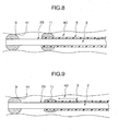
- Figure 8 shows a state where the balloon of the endoscope is blown up and fixed to the intestine wall in the state of Figure 7
- Figure 9 shows a state where the balloon of the overtube is deflated and the overtube is further inserted in the state of Figure 8
- Figure 10 shows a state where the tip of the overtube moves to the endoscope tip from the state of Figure 9
- Figure 11 shows a state where the balloon of the overtube is blown up and fixed to the intestine wall in the state of Figure
- an operator inserts the endoscope 2 into the overtube 3.
- the balloon 9 of the endoscope 2 and the balloon 11 of the overtube 3 are in a deflated state as air inside are drawn respectively, and the operator starts insertion of the endoscope 2 to the subject in this state.
- the operator presses down the gas sending start button 19b (see Figure 3) at the overtube side of the remote controller 8 to supply air into the balloon 11 for fixing the main body attached to the tip of the overtube 3 from the second pump 32b, blow up the balloon 11 and fix it to the intestines 40 of the overtube 3 as shown in Figure 6.
- the operator keeps the overtube 3 to the intestines 40 and inserts only the inserting unit 2B of the endoscope 2 into the deep part as shown in Figure 7.
- the operator presses down the gas sending start button 19a (see Figure 3) at the endoscope side of the remote controller 8 in a state where the inserting unit 2B of the endoscope 2 is inserted by a predetermined distance to supply air into the balloon 9 for fixing the main body attached to the tip of the endoscope 2 from the first pump 32a, blow up the balloon 9 and fix to the intestine wall 41 as shown in Figure 8.
- the operator presses down the release button 18b or the gas drawing start button 20b (see Figure 3) at the overtube side of the remote controller 8 to release air in the balloon 11 by the duct switching unit 33 or draw air in the balloon 11 of the overtube 3 from the second pump 32b and deflate the balloon 11 (see Figure 9).
- the operator inserts the overtube 3 to the deep part along the endoscope 2 and inserts the tip of the overtube 3 near the tip of the inserting unit 2B of the endoscope 2 as shown in Figure 9.
- the operator presses down the gas sending start button 19b (see Figure 3) at the overtube side of the remote controller 8 in the state where the tip of the overtube 3 is inserted near the tip of the inserting section 2B to supply air to the balloon 11 of the overtube 3 from the second pump 32b, blow up the balloon 11 and fix the overtube 3 to the intestines wall, as shown in Figure 11.
- Figure 12 is a flowchart for showing a main program of a control unit
- Figure 13 is a flowchart for showing a processing routine based on a switch state checking module of Figure 12
- Figure 14 is a flowchart for showing a processing routine based on a gas sending module of Figure 13
- Figure 15 is a flowchart for showing a processing routine based on a gas drawing module of Figure 13.
- control unit 35 When the control unit 35 checks the ON state of the power source by the process at the step S1, it performs initialization on various appliances and the like in the endoscope balloon control device 7 by the process at the step S2. As the initialization, for example, the control unit 35 starts the first and the second pumps 32a and 32b and performs initialization so that it is in a duct release state by the duct switching unit 33. The control unit 35 initializes by resetting an amount of flow counter, a timer count and the like (not shown) in the control unit 35.
- control unit 35 determines 20 msec timer interruption by the determination process at the following step S3; and if it determines that it occurred, it transfers the process to the step S4; and if it determines that it did not occur, it keeps performing the determination process.
- the control unit 35 determines whether the counter value of the timer counter for counting one by every 20 msec of the timer is equal to 10 or not by the determination process at the step S4; and if it determines that they are equal, it resets the timer counter and the amount of flow counter by the process at the step S5 and transfers the process to the step S6. On the other hand, if it determines that the counter value is not equal to 10, the control unit 35 transfers the process to the step S6.
- balloon control is performed according to manipulation of various buttons by the operator using the controller 8 by ten times of the processing routine shown in Figure 12, i.e., by the time unit of 200 msec.
- control unit 35 executes the processing routine based on the first pump and the second pump switch state checking module to be described later by the processes at the step S6 and the step S7. Then, after the processing routine based on the switch state checking module has been performed, the control unit 35 adds 1 to the counter value by the timer counter at the process at the step S8 and then returns the process to the determination process at the step S3.
- control unit 35 executes the process at the step S6, it starts the processing routine of the switch state checking module shown in Figure 13.
- the control unit 35 determines the presence of warning by whether the emergency stop button 23 of the remote controller 8 has been pressed down or not by the determination process at the step S11. In such a case, the control unit 35 performs the determination process by detecting ON/OFF of the warning flag.
- the warning flag is adapted to be turned ON not only by the emergency stop button 23 being pressed down but also by the control unit 35 when the endoscope balloon control device 7 has a problem and enters into a warning state.
- the control unit 35 determines that the endoscope balloon control unit 7 is in a warning state because of pressing down of the emergency stop button 23 or the like, and ends the processing routine based on the switch state checking module by the process at the step S20 to keep the current warning process and transfers to the process at the step 7 of Figure 12.
- the control unit 35 determines that the emergency stop button 23 is not pressed down and the endoscope balloon control device 7 is not in a warning state, and transfers to the determination process at the step S12.
- the control unit 35 determines whether the release button 18a of the remote controller 8 shown in Figure 3 is pressed down or not, and if it determines that it is not pressed down, it transfers to the step S14. On the other hand, if it determines that it is pressed down, the control unit 35 stops an operation of the first pump 32a corresponding to the release button 18a by the process at the step S13 and controls the duct switching unit 33 and the first amount of flow adjustment valve 32c so as to release the duct, and then it transfers to the step S20 and ends the processing routine based on the first pump switch state checking module.
- the control unit 35 determines whether the stop button 21a of the remote controller 8 shown in Figure 3 is pressed down or not, and if it determines that it is not pressed down, it transfers to the step S16. On the other hand, if it determines that it is pressed down, the control unit 35 controls the duct switching unit 33 and the first amount of flow adjustment valve 32c so as to close the duct (a duct keeping state) by the process at the step S15, and also stops the operation of the first pump 32a corresponding to the stop button 21a, and then transfers to the step S20 and ends the processing routine based on the first pump switch state checking module.
- the control unit 35 determines whether the gas drawing starting button 20a of the remote controller 8 shown in Figure 3 is pressed down or not; and if it determines that it is not pressed down, it transfers to the step S18. On the other hand, if it determines that it is pressed down, the control unit 35 starts the processing routine based on the gas drawing module shown in Figure 15 to be described later in the process at the step S17, performs gas drawing control corresponding to the gas drawing start button 20a, and then transfers to the step S20 and ends the processing routine based on the first pump switch state checking module.
- the control unit 35 determines whether the gas sending start button 19a of the remote controller 8 shown in Figure 3 is pressed down or not; and if it determines that it is not pressed down, it transfers to the step S20. On the other hand, if it determines that it is pressed down, the control unit 35 starts the processing routine based on a gas sending module shown in Figure 14 to be described later in the process at the step S19, and performs the gas sending control corresponding to the gas sending start button 19a, and then transfers to the step S20 and ends the processing routine based on the first pump switch state checking module.
- control unit 35 is adapted to previously set the pressure maximum value and the pressure upper limit value for comparing them with a pressure measured results from the fist and the second sensors 34a and 34b.
- the pressure upper limit value and the pressure maximum value fulfill relationship of the pressure limit value ⁇ the pressure maximum value.
- the pressure maximum value means the pressure value equal to cause each of the balloons 9 and 11 to be blown up to a dangerous state
- the pressure upper limit value means a pressure value equal to cause each of the balloons 9 and 11 to be blown up and fixed to the intestines.
- control unit 35 executes the process at the step S19, it starts the processing routine of the gas sending module shown in Figure 14.
- the control unit 35 compares a measured result from the first pressure sensor 34a (for example, a pressure analog value) and the previously set pressure maximum value in the determination process at the step S21; and if it determines that the measured result is smaller than the pressure maximum value, it transfers to the step S22; and if it determines that it is bigger, it transfers to the process at the step S29.
- the control unit 35 stops the operation of the first pump 32a and also controls the duct switching unit 33 and the first amount of flow adjustment valve 32c so as to release the duct. Then, the control unit 35 turns on the warning flag in the process at the step S30, then it transfers to the step S37 and ends the processing routine based on the gas sending module.
- the control unit 35 compares a measured result of measuring a gas sending time by an inner timer (gas sending time) and a previously set maximum gas sending time; and if it determines that the gas sending time is shorter than the maximum gas sending time, it transfers to the step 23; and if it determines that the gas sending time is longer than the maximum gas sending time, it transfers to the process at the step S31.
- the control unit 35 stops the operation of the first pump 32a as in the process at the step S29, and controls the duct switching unit 33 and the first amount of flow adjustment valve 32c so as to release the duct. Then, the control unit 35 turns on the warning flag in the process at the step S32 as in the process at the step S30, then transfers to the step S37 and ends the processing routine based on the gas sending module.
- the control unit 35 determines whether the counter value of the timer counter for counting one for every 20 msec of the timer is equal to 1 or not in the determination process at the step S23; and if it determines that it is equal, it stops the operation of the first pump 32a in the process at the step S33 and also controls the duct switching unit 33 and the first amount of flow adjustment valve 32c to keep the duct state. Then, the control unit 35 obtains a measured pressure value by performing pressure measurement by the first and the second pressure sensors 34a and 34b in the process at the step S34 and transfers to the step S24.
- the control unit 35 transfers to the step S24.
- control unit 35 obtains a measured pressure value by performing pressure measurement by the first pressure sensor 34a and compares the obtained measured pressure value (the measured pressure value obtained at the step S34 if it did via a loop of the steps S33 and S34) and a previously set pressure upper limit value in the determination process at the step S24; and if it determines that the measured result is smaller than the pressure upper limit value, it transfers to the step S25; and if it determines that the measured result is bigger than the pressure upper limit value, it transfers to the process at the step S35.
- control unit 35 stops the operation of the first pump 32a and also controls the duct switching unit 33 and the first amount of flow adjustment valve 32c so as to keep the duct state, then it transfers to the step S37 and ends the processing routine based on the gas sending module.
- control unit 35 compares the amount of flow counter value and a predetermined amount of flow of gas sent previously set (amount of flow of gas sent) in the determination process at the step S25; and if it determines that the amount of flow counter value is bigger than the predetermined amount of gas sent, it stops the operation of the first pump 32a in the process at the step S36 and also controls the duct switching unit 33 and the first amount of flow adjustment valve 32c so as to keep the duct state, and then it transfers to the step S37 and ends the processing routine based on the gas sending module.
- the amount of flow counter value is a variable for determining how much amount of gas can be sent in 200 msec (20 msec x 10), and can be set from 0 to 9 according to the timer counter value from 0 to 9, for example. Actually, the amount of flow counter (not shown) counts the amount of flow counter value for every 20 msec.
- the predetermined amount of gas sent indicates an approximate amount of gas sent (amount of gas sent) which can be sent for every 20 msec of the endoscope balloon control device 7.
- the control unit 35 controls the duct switching unit 33 to set a gas sending duct based on the gas sending start buttons 19a and 19b in the process at the step S27. Then, the control unit 35 adds 1 to the amount of flow counter value in the process at the step S27 and then adds 1 to the gas sending time in the process at the following step S28, and transfers to the step S37 and ends the processing routine based on the gas sending module.
- control unit 35 executes the process based on the second pump switch state checking module at the step S7 shown in Figure 12 assuming that the processing routine based on the switch state checking module shown in Figure 13 finished, and thereafter repeatedly executes the processes according to the processing routine shown in Figure 12. Only the operation of the second pump switch state checking module, and a pump, a switch and an object of control are changed, thus, the description of them will be omitted.
- control unit 35 executes the process of the step S17, it starts the process routine of a gas drawing module shown in Figure 15.
- control unit 35 compares the measured result of the gas drawing time measured by the inner timer (a gas drawing time) and a previously set maximum gas drawing time in the determination process at the step S40; and if it determines that the gas drawing time is shorter than the maximum gas drawing time, it transfers to the step S41; and if it determines that the gas drawing time is longer than the maximum gas drawing time, it transfers to the process at the step S47.
- control unit 35 stops the operation of the first pump 32a and also controls the duct switching unit 33 and the first amount of flow adjustment valve 32c to release the duct. Then, the control unit 35 turns on the warning flag in the process at the step S48 and then transfers to the step S53 and end s the processing routine based on the gas drawing module.
- the control unit 35 determines whether the counter value of the timer counter for counting 1 for each 20 msec of the timer is equal to 1 or not in the determination process at the step S41; and if it determines that it is equal, it stops the operation of the first pump 32a in the process at the step S49 and also controls the duct switching unit 33 and the first amount of flow adjustment valve 32c to keep the duct state. Then, the control unit 35 obtains a measured pressure value by performing pressure measurement by the first pressure sensor 34a in the process at the step S50, and transfers to the step S42.
- the control unit 35 transfers to the step S42.
- control unit 35 obtains a measured pressure value by performing pressure measurement by the first pressure sensor 34a and compares the obtained measured pressure value (the measured pressure value obtained at the step S50 if it did via a loop of the steps S49 and S50) and a previously set pressure lower limit value in the determination process at the step S42; and if it determines that the measured result is smaller than the pressure lower limit value, it transfers to the step S51; and if it determines that the measured result is bigger than the pressure lower limit value, it transfers to the process at the step S43.
- the control unit 35 stops the gas drawing operation of the first and the second pumps 32a and 32b and also controls the duct switching unit 33 and the first and the second amount of flow adjustment valves 32c and 32d so as to keep the duct, then it transfers to the step S53 and ends the processing routine based on the gas drawing module.
- the control unit 35 compares the amount of flow counter value and a predetermined amount of gas drawn previously set (amount of gas drawn) in the determination process at the step S43; and if it determines that the amount of flow counter value is bigger than the predetermined amount of gas drawn, it stops the gas drawing operation of the first pump 32a in the process at the step S52 and also controls the duct switching unit 33 and the first amount of flow adjustment valve 32c so as to keep the duct state, and then it transfers to the step S54 and ends the processing routine based on the gas drawing module.
- the predetermined amount of gas drawn indicates an approximate amount of gas drawn (amount of flow of air drawn) which can be drawn for every 20 msec of the endoscope balloon control unit 7.
- control unit 35 controls the duct switching unit 33 to set a gas drawing duct based on the gas drawing start button 20a in the process at the step S44. Then the control unit 35 adds 1 to the amount of flow counter value in the process at the step S45 and adds 1 to the gas drawing time in the process at the following step S46, and transfers to the step S53, and ends the processing routine based on the gas drawing module.
- control unit 35 executes the process based on the first pump control module at the step S7 shown in Figure 12 assuming that the processing routine based on the switch state checking module shown in Figure 13 finished, and thereafter repeatedly executes the process according to the processing routine shown in Figure 12.
- the endoscope balloon control device 7 can measure a gas sending time to the balloon 9 of the endoscope 2 and the balloon 11 of the overtube 3, it can control a pressure inside a balloon so as to release a duct by detecting that the maximum gas sending time, the maximum gas drawing time, the maximum gas sending pressure and the maximum gas drawing pressure are exceeded so that a procedure can be performed without applying great deal of force to the intestine wall.
- the endoscope balloon control device 7 can adjust the amount of flow of gas sent and an amount of flow of gas drawn to or from each of the balloons 9 and 11, it can be adapted to various materials of balloons or various parts.
- the endoscope balloon control device 7 can prevent a serial gas sending operation or a serial gas drawing operation which occurs when a duct such as the first and the second gas sending tubes 13 and 14 and the like, for example, come off.
- the present invention is not limited to that and can be configured with the operation unit 2A of the endoscope 2, which is at hand of the operator, or a foot switch for controlling the endoscope balloon control device 7 at the foot of the operator, for example.
- the controller 8 may be adapted to send various remote control operation signals using infrared radiation, receive the infrared radiation by a photoreceptor provided for the endoscope balloon control device 7 and capture the remote control signal. That further facilitates an operator's manipulation.
- Figure 16 is a configuration diagram showing an outlined configuration of the endoscope balloon control device according to the second embodiment of the present invention.
- Figure 16 gives the same reference numerals to the same components as those of the endoscope balloon control device of the first embodiment and omits the description of them, thus, only different parts will be described.
- the endoscope balloon control device 7 of the embodiment provides the first and the second relief valves 36a and 36b as pressure inside the balloon control means on gas sending ducts (gas sending lines) of two systems.
- the first relief valve 36a is connected to a duct at an output terminal side of the first pressure sensor 34a.
- the second relief valve 36b is connected to a duct at an output terminal side of the second pressure sensor 34b.
- the first and the second relief valves 36a and 36b are for preventing a pressure of a duct from being more than a predetermined pressure by monitoring pressure of ducts, and when the pressure of the duct becomes more than a predetermined pressure (a relief pressure), releasing the duct to the outside.
- first and the second relief valves 36a and 36b mechanical relief valves are used, for example, and the mechanical relief valves are adapted to release a valve fixed with elastic materials to the outside as the pressure inside the duct increases.
- the pressure upper limit value and the pressure maximum value are controlled by the electric type first and the second pressure sensors 34a and 34b which are pressure control methods different from the pressure inside the balloon control means (the first and the second relief valves 36a and 36b).
- An electromagnetic valve for adjusting the amount of flow (not shown) included in the first and the second amount of flow adjustment valves 32c and 32d is also an electric type and controlled by the control unit 35.
- both of the fist and the second pressure sensors 34a and 34b and the first and the second amount of flow adjustment valves 32c and 32d may stop their operations.
- outputs from the first and the second pumps 32a and 32b are directly applied into a living body so that a great deal of pressure may be applied. Even if an operation of a pressure sensor and an amount of flow adjustment valve corresponding to one of the gas sending ducts stops, an output from a corresponding pump may be directly applied into a living body.
- the endoscope balloon control device 7 of the embodiment decreases the applied pressure into a living body as the mechanical first and the second relief valves 36a and 36b which can operate regardless of the electric system failure, if a pressure to the living body exceeds a relief pressure in the abovementioned failure.
- the endoscope balloon control device 7 can decrease an applied pressure into a living body and also can normally operate the other gas sending duct as a corresponding relief valve operates.
- the endoscope balloon control device of the present invention is effective particularly in observation, treatment or the like on cases or various parts performed by changing materials of a balloon, as it can measure a gas sending time or a gas drawing time to a balloon of an endoscope and a balloon of an overtube so that an amount of flow of gas sent or a gas sending pressure to each of the balloons can be controlled.
Landscapes
- Health & Medical Sciences (AREA)
- Life Sciences & Earth Sciences (AREA)
- Surgery (AREA)
- Nuclear Medicine, Radiotherapy & Molecular Imaging (AREA)
- Biomedical Technology (AREA)
- Optics & Photonics (AREA)
- Pathology (AREA)
- Radiology & Medical Imaging (AREA)
- Biophysics (AREA)
- Engineering & Computer Science (AREA)
- Physics & Mathematics (AREA)
- Heart & Thoracic Surgery (AREA)
- Medical Informatics (AREA)
- Molecular Biology (AREA)
- Animal Behavior & Ethology (AREA)
- General Health & Medical Sciences (AREA)
- Public Health (AREA)
- Veterinary Medicine (AREA)
- Endoscopes (AREA)
Abstract
Description
- The present invention relates to an endoscope balloon control device, and relates to an endoscope balloon control device which can control pressures inside a balloon provided for a tip peripheral part of an inserting unit of an endoscope and a balloon provided for a tip peripheral part of an inserting unit of an overtube.
- Generally, endosocpy has been widely used in an alimentary canal examination. When an inserting unit of an endoscope is inserted in a deep alimentary canal, such as the small intestine in such an endoscope examination, it is difficult to insert the inserting unit into the deep part only by pushing the inserting unit in, as the intestines are complicatedly bent and it is hard to convey force to the tip of the inserting unit. For example, when the endoscope is drawn to pick up the extra bending or slack of the endoscope which was made during the deep insertion, the tip of the inserting unit is also drawn and the bending and the slack is not picked up, which makes the deep insertion difficult.
- An endoscope device adapted to prevent the tip of the inserting unit from being drawn when extra bending or slack of the endoscope is picked up by attaching a balloon to the tip peripheral part of the inserting unit of the endoscope and blowing up the balloon and temporally fixing it to the intestines are proposed.
- In the conventional art, an endoscope device which can improve operational performance of the endoscope device by providing an overtube through which the inserting unit of the endoscope is inserted and attaching a balloon at the tip peripheral part of the overtube and blowing up or deflating the balloon of the overtube and the balloon of the endoscope as required is proposed. For example, the
Japanese Patent Laid-Open No. 2002-301019 - In the endoscope device disclosed in the Patent Gazette, if the material of the balloon of the endoscope and the balloon of the overtube are different from each other or if material of a ballo on differs for each time the balloon is exchanged, the balloon blows up different ways even with the same amount of flow. Therefore, in order to keep a constant way of blowing up even if the materials and the type of the balloons are different, the amount of flow of gas sent to each of the balloons needs to be controlled according to the material of the balloon. In order to control the amount of flow of gas sent or a gas sending pressure to each of the balloons, a gas sending time to each of the balloons needs to be measured.
- In a conventional art described in the abovementioned
Japanese Patent Laid-Open No. 2002-301019 - The present invention is adapted in view of the circumstances, and it is an object of the invention to provide an endoscope balloon control device which can measure a gas sending time or a gas drawing time to or from a balloon of an endoscope and a balloon of an overtube.
- In order to achieve the abovementioned object, the endoscope balloon control device of the present invention comprises: a pump for supplying or discharging gas to or from a balloon for fixing attached to a peripheral part of a tip part of an inserting unit of an endoscope; a time detecting unit for detecting a gas sending time or a gas drawing time to or from the balloon; and a control unit for controlling a pressure inside the balloon by measuring the gas pressure inside the balloon and operating the pump based on the measured result, and also controlling a pressure inside the balloon based on the detected result by the time detecting unit.
-
- Figure 1 is a configuration diagram showing an entire configuration of an endoscope system to which an endoscope balloon control device is applied according to a first embodiment of the present invention;
- Figure 2 is a configuration diagram showing an outlined configuration of the endoscope balloon control device of Figure 1;
- Figure 3 is a diagram showing a configuration example of the remote controller of Figure 2;
- Figure 4 is a block diagram showing an inner configuration of the endoscope balloon control device of Figure 2;
- Figure 5 to Figure 11 are for illustrating an operation state of an endoscope and an overtube by using respective balloons, and Figure 5 is an illustration showing a state where respective balloons are deflated and the endoscope is inserted through the overtube and inserted in the intestines;
- Figure 6 is an illustration showing a state where a balloon for an overtube is blown up and fixed in the intestines;
- Figure 7 is an illustration showing a state where the endoscope is further inserted into the overtube from the state of Figure 6;
- Figure 8 is an illustration showing a state where the balloon of the endoscope is blown up and fixed to the wall of the intestines in the state of Figure 7;
- Figure 9 is an illustration showing a state where the balloon of the overtube is deflated and the overtube is further inserted in the state of Figure 8;
- Figure 10 is an illustration showing a state where the tip of the overtube moves to the tip part of the endoscope from the state of Figure 9;
- Figure 11 is an illustration showing a state where the balloon of the overtube is blown up and fixed to the wall of the intestines in the state of Figure 10;
- Figure 12 to Figure 15 are flowcharts for illustrating an operation of an endoscope balloon control device, and Figure 12 is a flowchart showing a main program of a control unit;
- Figure 13 is a flowchart showing a processing routine based on the switch state checking module of Figure 12;
- Figure 14 is a flowchart showing a processing routine based on the gas sending module of Figure 13;
- Figure 15 is a flowchart for showing a processing routine based on the gas drawing module of Figure 13; and
- Figure 16 is a block diagram showing an inner configuration of the endoscope balloon control device according to a second embodiment.
- Embodiments of the present invention will be described with reference to the drawings.
- Figure 1 is a configuration diagram showing an entire configuration of an endoscope system applied with an endoscope balloon control device according to a first embodiment of the present invention.
- As shown in Figure 1, an
endoscope system 1 having an endoscope balloon control device of the embodiment has anendoscope 2, anovertube 3, alight source device 4, avideo processor 5, amonitor 6, an endoscopeballoon control device 7 and aremote controller 8. - The
endoscope 2 is used for an alimentary canal endoscope examination, for example, having aninserting unit 2B to be inserted in a body cavity and anoperation unit 2A provided at a base end side of theinserting unit 2B. An observation optical system including an illumination optical system and a CCD which is an image pickup device (not shown) is provided in the tip part of theinserting unit 2B and illuminates an observed part in the alimentary canal of a subject body and can obtain an observation image in the alimentary canal of the subject body. - A
universal code 2C is extending out from theoperation unit 2A. Inside theuniversal code 2C, a signal line and a light guide cable (not shown) are provided. The base end part of theuniversal code 2C is connected to aconnector 4a of thelight source device 4 and aconnector 5a of thevideo processor 5. Accordingly, illumination light from thelight source device 4 is supplied to the illumination optical system of theendoscope 2 via the light guide cable in theuniversal code 2C and illuminates the observed part, and outputs an image pick up signal in the alimentary canal outputted from the CCD to thevideo processor 5. - Such an
endoscope 2 is adapted to be used inserted through theovertube 3 during an operation. A configuration of theovertube 3 will be described later. - The
light source device 4 is a light source device for supplying illumination light to the illumination optical system provided for theendoscope 2 via a light guide (not shown) in the light guide cable. - The
video processor 5 performs signal processing on an image pickup signal from the CCD of theendoscope 2 and supplies image data based on the image pickup signal (for example, endoscope live image data) to themonitor 6. - The
monitor 6 is connected to thevideo processor 5 by a connectingcable 5A. Themonitor 6 displays an endoscope image based on image data from thevideo processor 5. - In the
endoscope system 1 of the embodiment, afixing balloon 9 is attached to the tip peripheral part of theinserting unit 2B of theendoscope 2. Anair supplying tube 10 provided along theinserting unit 2B from the base end part side to the tip part side of theinserting unit 2B is connected to theballoon 9. - The base end part of the
operation unit 2A of theair supplying tube 10 is connected to theconnector 2a provided at the bottom of theoperation unit 2A. To theconnector 2a is connected aconnector 13A which is provided at one end of an endoscope balloon gas sending tube (hereinafter, referred to as the first gas sending tube) 13, the other end of which is connected to an endoscopeballoon control device 7 to be described later. Thus, theballoon 9 is blown up by gas sent from the endoscopeballoon control device 7 and temporally fixed to the alimentary canal such as the intestinal canal. - The
overtube 3 is for guiding theinserting unit 2B to be inserted in the alimentary canal, for example, by inserting theendoscope 2 through it, and has a little bit bigger inside diameter than the external diameter of theinserting unit 2B of the endoscope. Theovertube 3 has a configuration with the same flexibility as theinserting unit 2B of theendoscope 2. Further, to the tip peripheral part of theovertube 3, atube fixing balloon 11 is attached. - To the
balloon 11, anair supplying tube 12 provided for theovertube 3 from its base end part side to its tip part side is connected. - The base end part at the opposite side of the
balloon 11 of the air supplying tube 12 (an inserting slot side for inserting theendoscope 2 of the overtube 3) is connected to aconnector 3a provided near the inserting slot of theovertube 3. To theconnector 3a is connected aconnector 14A which is provided at one end of an overtube balloon gas sending tube (hereinafter referred to as a second gas sending tube) 14, the other end of which is connected to the endoscopeballoon control device 7. Thus, theballoon 11 is blown up by gas sent from the endoscopeballoon control device 7 and temporally fixed to the alimentary canal such as the intestine canal. - The endoscope
balloon control device 7 is for controlling various operations on the amount of flow of gas sent of theballoon 9 of theendoscope 2 and theballoon 11 of theovertube 3 and the like. - Figure 2 is a configuration diagram showing an outlined configuration of the endoscope balloon control device.
- As shown in Figure 2, a
backflow prevention tank 15 is provided for the endoscopeballoon control device 7, and apressure display device 16 and a power source switch 17 are provided at the front side of thedevice 7. - The
backflow prevention tank 15 is adapted to be able to prevent backflow of a liquid, having atank 15A for theballoon 9 of theendoscope 2 and atank 15B for theballoon 11 of theovertube 3. The first and the second gas sending tubes 13 and 14 are connected to the correspondingtanks - The
tanks balloons second pumps balloon control device 7, respectively. In such a case, thetanks - As such, a gas sending duct via the
air supplying tube 10 connected to theballoon 9 of theendoscope 2, the first gas sending tube 13, and thetank 15A, a gas sending duct via theair supplying tube 12 connected to theballoon 11 of theovertube 3, the second gas sending tube 14, and thetank 15B are provided for the endoscopeballoon control device 7 of the embodiment. - The
pressure display device 16 is for displaying a pressure value of ducts connected to theballoons pressure display device 16 has adisplay device 16A for theballoon 9 of theendoscope 2 and adisplay device 16B for theballoon 11 of theovertube 3. - The
display device 16A displays a pressure value inside the duct for theballoon 9 of theendoscope 2, and thedisplay device 16B displays a pressure value inside the duct for theballoon 11 of theovertube 3. - The
power source switch 17 is a switch for switching the power source of the endoscopeballoon control device 7 between ON and OFF. - As shown in Figure 1 and Figure 2, the
remote controller 8 is connected to a side of the endoscopeballoon control device 7 via a connectingcable 8A. Theremote controller 8 is electrically connected to acontrol unit 35 provide d inside the endoscopeballoon control device 7 to be described later via the connectingcable 8A. - In the embodiment, the endoscope
balloon control device 7 is adapted to be supplied with an operation signal for pressure control and gas sending control of each of theballoons remote controller 8 during an operation. - Figure 3 is a diagram showing a configuration example of the
remote controller 8. - As shown in Figure 3, the
remote controller 8 is set up as its various buttons for controlling an endoscope side balloon and various buttons for controlling an overtube side balloon are divided into right and left of the main body of the remote controller, for example, for facilitating manipulation of the operator. - At the left side of the
remote controller 8, arelease button 18a, a gas sendingstart button 19a, a gasdrawing start button 20a and astop button 21a are provided as operation buttons for controlling the endoscope side balloon. - To the right side of the
remote controller 8, arelease button 18b, a gas sendingstart button 19b, agas drawing button 20b and astop button 21b are provided as operation buttons for controlling the overtube side balloon. - Further, a
power source button 22, and anemergency stop button 23 are provided at the bottom of theremote controller 8. - The
release button 18a is a button for indicating to release air in a duct of theballoon 9 of theendoscope 2. The gas sendingstart button 19a is a button for indicting to start sending gas into theballoon 9 of theendoscope 2. The gasdrawing start button 20a is a button for indicating to start drawing gas from theballoon 9 of theendoscope 2. Thestop button 21a is a button for performing indication to stop a gas sending operation by the gas sendingstart button 19a or a gas drawing operation by the gasdrawing start button 20a. As thestop button 21a is pressed down, an air pressure inside theballoon 9 can be kept. - On the other hand, the
release button 18b is a button for indicating to release air inside the duct of theballoon 11 of theovertube 3. The gas sendingstart button 19b is a button for indicating to start sending gas into theballoon 11 of theovertube 3. The gasdrawing start button 20b is a button for indicating to start drawing gas from theballoon 11 of theovertube 3. Thestop button 21b is a button for performing indication to stop a gas sending operation by the gas sendingstart button 19b and a gas drawing operation by the gasdrawing start button 20b. As thestop button 21b is pressed down, an air pressure inside theballoon 11 or a duct can be kept. - The
power source switch 22 is a button for switching the power source of the endoscopeballoon control device 7 between the ON state and the OFF state. - The
emergency stop button 23 is a button for directly turning off the first to thethird breaker 31a to 31c to be described later of the endoscopeballoon control device 7 and perform emergency stop on gas sending control of each of theballoons balloon control device 7. - Next, an inner configuration of the endoscope
balloon control device 7 will be described with reference to Figure 4. Figure 4 is a block diagram showing an inner configuration of the endoscope balloon control device. - As shown in Figure 4, the endoscope
balloon control device 7 has a switchingpower source unit 30, a first to athird breakers 31a to 31c, a first and asecond pumps flow adjustment valves duct switching unit 33, a first and asecond pressure sensors control unit 35 which is the control means. - To the switching
power source unit 30, AC power is supplied from an external commercial power source via a connecting code (not shown). The switchingpower source unit 30 converts the supplied AC power into DC power and supplies it to the first to thethird breakers 31a to 31c, the first and thesecond pressure sensors control unit 35 and theemergency stop button 23 of theremote controller 8. - The
first breaker 31a is electrically connected to the first and thesecond pumps emergency stop button 23 of theremote controller 8. Thefirst breaker 31a supplies DC power to the first and thesecond pumps emergency stop button 23, supplying of DC power to the first and thesecond pumps - The
second breaker 31b is electrically connected to theduct switching unit 33 and theemergency stop button 23 of theremote controller 8. Thesecond breaker 31b supplies DC power to theduct switching unit 33. If an operation signal is supplied from theemergency stop button 23, supplying of DC power to theduct switching unit 33 is stopped. - The
third breaker 31c is electrically connected to the first and the second amount offlow adjustment valves emergency stop button 23 of theremote controller 8. Thethird breaker 31c supplies DC power to the first and the second amount offlow adjustment valves emergency stop button 23, supplying of DC power to the first and the second amount offlow adjustment valves - The first and the
second pumps duct switching unit 33 via an air line, respectively. The first and thesecond pumps control unit 35. For example, they are adapted to s end air to theduct switching unit 33 via the air line, or, on the contrary, to draw air from theduct switching unit 33 via the air line. - To the output side of the
duct switching unit 33, the first and the second amount offlow adjustment valves flow adjustment valves control unit 35, and makes adjustment of the amount of flow of air to be output based on a control signal from thecontrol unit 35. The first and the second amount offlow adjustment valves second pressure sensors - The fist and
second pressure sensors flow adjustment valves second pressure sensors 34a and 35b may be supplied to thecontrol unit 35 and thecontrol unit 35 may be adapted to control the first and thesecond pumps - Outputs from the first and the
second pressure sensors connectors - As such, the endoscope
balloon control device 7 has a gas sending duct comprising the first amount offlow adjustment valve 32c and thefirst pressure sensor 34a via thefist pump 32a and theduct switching unit 33, and a gas sending duct comprising the second amount offlow adjustment valve 32d and thesecond pressure sensor 34b via thesecond pump 32b and theduct switching unit 33. - The
duct switching unit 33 can switch ducts (not shown) provided inside so as to make it a duct state according to an executing mode in the endoscopeballoon control device 7. For example, as the executing mode, there are four executing modes such as a gas sending mode, a gas drawing mode, a keeping mode, and a releasing mode. Therefore, theduct switching unit 33 can switch an inner duct (not shown) to make it a state according to the four modes, i.e., a gas sending state, a gas drawing state, a keeping state, and a releasing state. The switching can be controlled based on a control signal from thecontrol unit 35. As a result, it is adapted to make the duct at theballoon 9 side of theendoscope 2 and the duct at theballoon 11 side of theovertube side 3 connected to the back side duct states based on respective desired executing modes. - Although they are not shown, the
control unit 35 has an amount of flow counter for counting the amount of flow of gas sent to theballoon 9 of theendoscope 2 and theballoon 11 of theovertube 3; a timer counter, which is the gas sending time detecting means for counting each of a gas sending time and a gas drawing time of theballoons - The
control unit 35 is adapted to control the first and thesecond pumps duct switching unit 33 and the first and the second amount offlow adjustment valves remote controller 8. - Then, the endoscope
balloon control device 7 is adapted to be able to measure a gas sending time or a gas drawing time to or from theballoon 9 of theendoscope 2 and theballoon 11 of theovertube 3, and time of the amount of flow of gas sent and the like, and control the amount of flow of gas sent to theballoon 9 of theendoscope 2 and theballoon 11 of theovertube 3 by using the measured result. - Next, a basic operation state of the
endoscope system 1 will be described with reference to Figure 5 to Figure 11. - From Figure 5 to Figure 11 are illustrations describing a n operation state of an
endoscope 2 and an overtube by using the balloon of the endoscope and the balloon of the overtube. Figure 5 shows a state where each balloon is deflated and an endoscope is inserted through the overtube and inserted into the intestines; Figure 6 shows a state where the balloon of the overtube is blown up and fixed to the intestines; Figure 7 is a state where the endoscope is further inserted into the overtube from the state of Figure 6; Figure 8 shows a state where the balloon of the endoscope is blown up and fixed to the intestine wall in the state of Figure 7; Figure 9 shows a state where the balloon of the overtube is deflated and the overtube is further inserted in the state of Figure 8; Figure 10 shows a state where the tip of the overtube moves to the endoscope tip from the state of Figure 9; and Figure 11 shows a state where the balloon of the overtube is blown up and fixed to the intestine wall in the state of Figure 10, respectively. - As shown in Figure 5, an operator inserts the
endoscope 2 into theovertube 3. In such a case, theballoon 9 of theendoscope 2 and theballoon 11 of theovertube 3 are in a deflated state as air inside are drawn respectively, and the operator starts insertion of theendoscope 2 to the subject in this state. - Next, when the operator inserted the tip of the
endoscope 2 and theovertube 3 to, for example, a descending leg of duodenum, the operator presses down the gas sendingstart button 19b (see Figure 3) at the overtube side of theremote controller 8 to supply air into theballoon 11 for fixing the main body attached to the tip of theovertube 3 from thesecond pump 32b, blow up theballoon 11 and fix it to theintestines 40 of theovertube 3 as shown in Figure 6. Next, the operator keeps theovertube 3 to theintestines 40 and inserts only the insertingunit 2B of theendoscope 2 into the deep part as shown in Figure 7. - Then, the operator presses down the gas sending
start button 19a (see Figure 3) at the endoscope side of theremote controller 8 in a state where the insertingunit 2B of theendoscope 2 is inserted by a predetermined distance to supply air into theballoon 9 for fixing the main body attached to the tip of theendoscope 2 from thefirst pump 32a, blow up theballoon 9 and fix to theintestine wall 41 as shown in Figure 8. - Some patients may have
narrow intestines balloons intestines intestines stop buttons balloons - Next, the operator presses down the
release button 18b or the gasdrawing start button 20b (see Figure 3) at the overtube side of theremote controller 8 to release air in theballoon 11 by theduct switching unit 33 or draw air in theballoon 11 of theovertube 3 from thesecond pump 32b and deflate the balloon 11 (see Figure 9). - Next, the operator inserts the
overtube 3 to the deep part along theendoscope 2 and inserts the tip of theovertube 3 near the tip of the insertingunit 2B of theendoscope 2 as shown in Figure 9. - Then, the operator presses down the gas sending
start button 19b (see Figure 3) at the overtube side of theremote controller 8 in the state where the tip of theovertube 3 is inserted near the tip of the insertingsection 2B to supply air to theballoon 11 of theovertube 3 from thesecond pump 32b, blow up theballoon 11 and fix theovertube 3 to the intestines wall, as shown in Figure 11. - The operator presses down the
release button 18a or the gasdrawing start button 20a at the endoscope side of the remote controller 8 (see Figure 3) to release air in theballoon 9 by theduct switching unit 33 or draw air in theballoon 9 of theendoscope 2 from thefirst pump 32a and deflate theballoon 9 and further insert the insertingunit 2B to the deep part. - As the manipulations from Figure 5 to Figure 11 are repeated, insertion of the
endoscope 2 and theovertube 3 into the deep part is advanced, so that the insertingunit 2B of theendoscope 2 can be inserted to a desired place. - Next, operations of the endoscope balloon control device of the embodiment will be described with reference to Figure 12 to Figure 15.
- From Figure 12 to Figure 15 are for describing operations of the endoscope balloon control device and; Figure 12 is a flowchart for showing a main program of a control unit; Figure 13 is a flowchart for showing a processing routine based on a switch state checking module of Figure 12; Figure 14 is a flowchart for showing a processing routine based on a gas sending module of Figure 13; and Figure 15 is a flowchart for showing a processing routine based on a gas drawing module of Figure 13.
- It is assumed that an operator performs an endoscope examination in the alimentary canal by using the
endoscope system 1 of Figure 1. When the operator presses down apower source button 22 of theremote controller 8 shown in Figure 3 (or a power source switch 17 shown in Figure 2), thecontrol unit 35 reads in a main program shown in Figure 12 from a storing unit (not shown) inside and starts it. - When the
control unit 35 checks the ON state of the power source by the process at the step S1, it performs initialization on various appliances and the like in the endoscopeballoon control device 7 by the process at the step S2. As the initialization, for example, thecontrol unit 35 starts the first and thesecond pumps duct switching unit 33. Thecontrol unit 35 initializes by resetting an amount of flow counter, a timer count and the like (not shown) in thecontrol unit 35. - Then, the
control unit 35 determines 20 msec timer interruption by the determination process at the following step S3; and if it determines that it occurred, it transfers the process to the step S4; and if it determines that it did not occur, it keeps performing the determination process. - For the timer, one for measuring 20 msec is used for operating the processing routine by every 20 msec shown in Figure 12.
- Then, the
control unit 35 determines whether the counter value of the timer counter for counting one by every 20 msec of the timer is equal to 10 or not by the determination process at the step S4; and if it determines that they are equal, it resets the timer counter and the amount of flow counter by the process at the step S5 and transfers the process to the step S6. On the other hand, if it determines that the counter value is not equal to 10, thecontrol unit 35 transfers the process to the step S6. - In the embodiment, it is assumed that balloon control is performed according to manipulation of various buttons by the operator using the
controller 8 by ten times of the processing routine shown in Figure 12, i.e., by the time unit of 200 msec. - Next, the
control unit 35 executes the processing routine based on the first pump and the second pump switch state checking module to be described later by the processes at the step S6 and the step S7. Then, after the processing routine based on the switch state checking module has been performed, thecontrol unit 35 adds 1 to the counter value by the timer counter at the process at the step S8 and then returns the process to the determination process at the step S3. - Next, the processing routine of the first pump switch state checking module by the step S6 will be described with reference to Figure 13.
- When the
control unit 35 executes the process at the step S6, it starts the processing routine of the switch state checking module shown in Figure 13. - Then, the
control unit 35 determines the presence of warning by whether theemergency stop button 23 of theremote controller 8 has been pressed down or not by the determination process at the step S11. In such a case, thecontrol unit 35 performs the determination process by detecting ON/OFF of the warning flag. The warning flag is adapted to be turned ON not only by theemergency stop button 23 being pressed down but also by thecontrol unit 35 when the endoscopeballoon control device 7 has a problem and enters into a warning state. - Here, when it is detected that the warning flag is turned ON, the
control unit 35 determines that the endoscopeballoon control unit 7 is in a warning state because of pressing down of theemergency stop button 23 or the like, and ends the processing routine based on the switch state checking module by the process at the step S20 to keep the current warning process and transfers to the process at thestep 7 of Figure 12. - On the other hand, if it is detected that the warning flag is OFF by the determination process at the step S11, the
control unit 35 determines that theemergency stop button 23 is not pressed down and the endoscopeballoon control device 7 is not in a warning state, and transfers to the determination process at the step S12. - At the determination process at the step S12, the
control unit 35 determines whether therelease button 18a of theremote controller 8 shown in Figure 3 is pressed down or not, and if it determines that it is not pressed down, it transfers to the step S14. On the other hand, if it determines that it is pressed down, thecontrol unit 35 stops an operation of thefirst pump 32a corresponding to therelease button 18a by the process at the step S13 and controls theduct switching unit 33 and the first amount offlow adjustment valve 32c so as to release the duct, and then it transfers to the step S20 and ends the processing routine based on the first pump switch state checking module. - In the determination process at the step S14, the
control unit 35 determines whether thestop button 21a of theremote controller 8 shown in Figure 3 is pressed down or not, and if it determines that it is not pressed down, it transfers to the step S16. On the other hand, if it determines that it is pressed down, thecontrol unit 35 controls theduct switching unit 33 and the first amount offlow adjustment valve 32c so as to close the duct (a duct keeping state) by the process at the step S15, and also stops the operation of thefirst pump 32a corresponding to thestop button 21a, and then transfers to the step S20 and ends the processing routine based on the first pump switch state checking module. - In the determination process at the step S16, the
control unit 35 determines whether the gasdrawing starting button 20a of theremote controller 8 shown in Figure 3 is pressed down or not; and if it determines that it is not pressed down, it transfers to the step S18. On the other hand, if it determines that it is pressed down, thecontrol unit 35 starts the processing routine based on the gas drawing module shown in Figure 15 to be described later in the process at the step S17, performs gas drawing control corresponding to the gasdrawing start button 20a, and then transfers to the step S20 and ends the processing routine based on the first pump switch state checking module. - In the determination process at the step S18, the
control unit 35 determines whether the gas sendingstart button 19a of theremote controller 8 shown in Figure 3 is pressed down or not; and if it determines that it is not pressed down, it transfers to the step S20. On the other hand, if it determines that it is pressed down, thecontrol unit 35 starts the processing routine based on a gas sending module shown in Figure 14 to be described later in the process at the step S19, and performs the gas sending control corresponding to the gas sendingstart button 19a, and then transfers to the step S20 and ends the processing routine based on the first pump switch state checking module. - Next, the processing routine of the gas sending module at the step S19 will be described with reference to Figure 14.
- In the embodiment, the
control unit 35 is adapted to previously set the pressure maximum value and the pressure upper limit value for comparing them with a pressure measured results from the fist and thesecond sensors balloons balloons - When the
control unit 35 executes the process at the step S19, it starts the processing routine of the gas sending module shown in Figure 14. - Then, the
control unit 35 compares a measured result from thefirst pressure sensor 34a (for example, a pressure analog value) and the previously set pressure maximum value in the determination process at the step S21; and if it determines that the measured result is smaller than the pressure maximum value, it transfers to the step S22; and if it determines that it is bigger, it transfers to the process at the step S29. In the process at the step S29, thecontrol unit 35 stops the operation of thefirst pump 32a and also controls theduct switching unit 33 and the first amount offlow adjustment valve 32c so as to release the duct. Then, thecontrol unit 35 turns on the warning flag in the process at the step S30, then it transfers to the step S37 and ends the processing routine based on the gas sending module. - In the process at the step S22, the
control unit 35 compares a measured result of measuring a gas sending time by an inner timer (gas sending time) and a previously set maximum gas sending time; and if it determines that the gas sending time is shorter than the maximum gas sending time, it transfers to thestep 23; and if it determines that the gas sending time is longer than the maximum gas sending time, it transfers to the process at the step S31. - In the process at the step S31, the
control unit 35 stops the operation of thefirst pump 32a as in the process at the step S29, and controls theduct switching unit 33 and the first amount offlow adjustment valve 32c so as to release the duct. Then, thecontrol unit 35 turns on the warning flag in the process at the step S32 as in the process at the step S30, then transfers to the step S37 and ends the processing routine based on the gas sending module. - Then, the
control unit 35 determines whether the counter value of the timer counter for counting one for every 20 msec of the timer is equal to 1 or not in the determination process at the step S23; and if it determines that it is equal, it stops the operation of thefirst pump 32a in the process at the step S33 and also controls theduct switching unit 33 and the first amount offlow adjustment valve 32c to keep the duct state. Then, thecontrol unit 35 obtains a measured pressure value by performing pressure measurement by the first and thesecond pressure sensors - In the determination process at the step S23, if it determines that the counter value of the timer counter is not equal to 1, the
control unit 35 transfers to the step S24. - Then, the
control unit 35 obtains a measured pressure value by performing pressure measurement by thefirst pressure sensor 34a and compares the obtained measured pressure value (the measured pressure value obtained at the step S34 if it did via a loop of the steps S33 and S34) and a previously set pressure upper limit value in the determination process at the step S24; and if it determines that the measured result is smaller than the pressure upper limit value, it transfers to the step S25; and if it determines that the measured result is bigger than the pressure upper limit value, it transfers to the process at the step S35. - In the process at the step S35, the
control unit 35 stops the operation of thefirst pump 32a and also controls theduct switching unit 33 and the first amount offlow adjustment valve 32c so as to keep the duct state, then it transfers to the step S37 and ends the processing routine based on the gas sending module. - Next, the
control unit 35 compares the amount of flow counter value and a predetermined amount of flow of gas sent previously set (amount of flow of gas sent) in the determination process at the step S25; and if it determines that the amount of flow counter value is bigger than the predetermined amount of gas sent, it stops the operation of thefirst pump 32a in the process at the step S36 and also controls theduct switching unit 33 and the first amount offlow adjustment valve 32c so as to keep the duct state, and then it transfers to the step S37 and ends the processing routine based on the gas sending module. - The amount of flow counter value is a variable for determining how much amount of gas can be sent in 200 msec (20 msec x 10), and can be set from 0 to 9 according to the timer counter value from 0 to 9, for example. Actually, the amount of flow counter (not shown) counts the amount of flow counter value for every 20 msec. The predetermined amount of gas sent indicates an approximate amount of gas sent (amount of gas sent) which can be sent for every 20 msec of the endoscope
balloon control device 7. - If the amount of flow counter value is smaller than the predetermined amount of gas sent in the determination process at the step S25, the
control unit 35 controls theduct switching unit 33 to set a gas sending duct based on the gas sendingstart buttons control unit 35 adds 1 to the amount of flow counter value in the process at the step S27 and then adds 1 to the gas sending time in the process at the following step S28, and transfers to the step S37 and ends the processing routine based on the gas sending module. - When the processing routine based on the gas sending module ends, the
control unit 35 executes the process based on the second pump switch state checking module at the step S7 shown in Figure 12 assuming that the processing routine based on the switch state checking module shown in Figure 13 finished, and thereafter repeatedly executes the processes according to the processing routine shown in Figure 12. Only the operation of the second pump switch state checking module, and a pump, a switch and an object of control are changed, thus, the description of them will be omitted. - Next, the processing routine of the gas drawing module at the step S17 shown in Figure 13 will be described with reference to Figure 15.
- When the
control unit 35 executes the process of the step S17, it starts the process routine of a gas drawing module shown in Figure 15. - Then, the
control unit 35 compares the measured result of the gas drawing time measured by the inner timer (a gas drawing time) and a previously set maximum gas drawing time in the determination process at the step S40; and if it determines that the gas drawing time is shorter than the maximum gas drawing time, it transfers to the step S41; and if it determines that the gas drawing time is longer than the maximum gas drawing time, it transfers to the process at the step S47. - In the process at the step S47, the
control unit 35 stops the operation of thefirst pump 32a and also controls theduct switching unit 33 and the first amount offlow adjustment valve 32c to release the duct. Then, thecontrol unit 35 turns on the warning flag in the process at the step S48 and then transfers to the step S53 and end s the processing routine based on the gas drawing module. - Then, the
control unit 35 determines whether the counter value of the timer counter for counting 1 for each 20 msec of the timer is equal to 1 or not in the determination process at the step S41; and if it determines that it is equal, it stops the operation of thefirst pump 32a in the process at the step S49 and also controls theduct switching unit 33 and the first amount offlow adjustment valve 32c to keep the duct state. Then, thecontrol unit 35 obtains a measured pressure value by performing pressure measurement by thefirst pressure sensor 34a in the process at the step S50, and transfers to the step S42. - In the determination process at the step S41, if it determines that the counter value of the timer counter is not equal to 1, the
control unit 35 transfers to the step S42. - Then, the
control unit 35 obtains a measured pressure value by performing pressure measurement by thefirst pressure sensor 34a and compares the obtained measured pressure value (the measured pressure value obtained at the step S50 if it did via a loop of the steps S49 and S50) and a previously set pressure lower limit value in the determination process at the step S42; and if it determines that the measured result is smaller than the pressure lower limit value, it transfers to the step S51; and if it determines that the measured result is bigger than the pressure lower limit value, it transfers to the process at the step S43. - In the process at the step S51, the
control unit 35 stops the gas drawing operation of the first and thesecond pumps duct switching unit 33 and the first and the second amount offlow adjustment valves - Next, the
control unit 35 compares the amount of flow counter value and a predetermined amount of gas drawn previously set (amount of gas drawn) in the determination process at the step S43; and if it determines that the amount of flow counter value is bigger than the predetermined amount of gas drawn, it stops the gas drawing operation of thefirst pump 32a in the process at the step S52 and also controls theduct switching unit 33 and the first amount offlow adjustment valve 32c so as to keep the duct state, and then it transfers to the step S54 and ends the processing routine based on the gas drawing module. The predetermined amount of gas drawn indicates an approximate amount of gas drawn (amount of flow of air drawn) which can be drawn for every 20 msec of the endoscopeballoon control unit 7. - If it determines that the amount of flow counter value is smaller than the predetermined amount of gas drawn in the determination process at the step S43, the
control unit 35 controls theduct switching unit 33 to set a gas drawing duct based on the gasdrawing start button 20a in the process at the step S44. Then thecontrol unit 35 adds 1 to the amount of flow counter value in the process at the step S45 and adds 1 to the gas drawing time in the process at the following step S46, and transfers to the step S53, and ends the processing routine based on the gas drawing module. - When the processing routine based on the gas drawing module ends, the
control unit 35 executes the process based on the first pump control module at the step S7 shown in Figure 12 assuming that the processing routine based on the switch state checking module shown in Figure 13 finished, and thereafter repeatedly executes the process according to the processing routine shown in Figure 12. - As mentioned above, according to the embodiment, as the endoscope
balloon control device 7 can measure a gas sending time to theballoon 9 of theendoscope 2 and theballoon 11 of theovertube 3, it can control a pressure inside a balloon so as to release a duct by detecting that the maximum gas sending time, the maximum gas drawing time, the maximum gas sending pressure and the maximum gas drawing pressure are exceeded so that a procedure can be performed without applying great deal of force to the intestine wall. - As the endoscope
balloon control device 7 can adjust the amount of flow of gas sent and an amount of flow of gas drawn to or from each of theballoons balloon control device 7 can prevent a serial gas sending operation or a serial gas drawing operation which occurs when a duct such as the first and the second gas sending tubes 13 and 14 and the like, for example, come off. - In the embodiment, although a configuration of the
remote controller 8 connected to the endoscopeballoon control device 7 has been described, the present invention is not limited to that and can be configured with theoperation unit 2A of theendoscope 2, which is at hand of the operator, or a foot switch for controlling the endoscopeballoon control device 7 at the foot of the operator, for example. - The
controller 8 may be adapted to send various remote control operation signals using infrared radiation, receive the infrared radiation by a photoreceptor provided for the endoscopeballoon control device 7 and capture the remote control signal. That further facilitates an operator's manipulation. - Figure 16 is a configuration diagram showing an outlined configuration of the endoscope balloon control device according to the second embodiment of the present invention. Figure 16 gives the same reference numerals to the same components as those of the endoscope balloon control device of the first embodiment and omits the description of them, thus, only different parts will be described.
- The endoscope
balloon control device 7 of the embodiment provides the first and thesecond relief valves - As shown in Figure 16, the
first relief valve 36a is connected to a duct at an output terminal side of thefirst pressure sensor 34a. Thesecond relief valve 36b is connected to a duct at an output terminal side of thesecond pressure sensor 34b. - The first and the
second relief valves - In the embodiment, for the first and the
second relief valves - The other configurations are the same as those in the first embodiment.
- The operation of the embodiment will be described with reference to Figure 16.
- In the endoscope
balloon control device 7 shown in Figure 16, the respective relief pressures are set so as to satisfy,
pressure upper limit value < pressure maximum value =< relief pressure. - Generally, the pressure upper limit value and the pressure maximum value are controlled by the electric type first and the
second pressure sensors second relief valves flow adjustment valves control unit 35. - Therefore, as the first and the
second pressure sensors flow adjustment valves second pressure sensors flow adjustment valves - In such a case, outputs from the first and the
second pumps - The endoscope
balloon control device 7 of the embodiment, however, decreases the applied pressure into a living body as the mechanical first and thesecond relief valves - Even if an operation of a pressure sensor and an amount of flow adjustment valve corresponding to a gas sending duct of one of the gas sending ducts of two systems (gas sending lines) stops but a pressure to a living body exceeds a relief pressure, the endoscope
balloon control device 7 can decrease an applied pressure into a living body and also can normally operate the other gas sending duct as a corresponding relief valve operates. - The other operations are the same as those of the first embodiment.
- Therefore, according to the embodiment, the same effects as those of the first embodiment are obtained and an endoscope balloon control device having pressure inside the balloon control means which can ensure safety also to failure such as in an electric system can be realized.
- In the present invention, it is apparent that different embodiments in a wide range can be adapted based on the present invention without departing from the spirit and the scope of the present invention. The present invention is not limited by particular embodiments except for being limited by the range of the attached claims.
- The endoscope balloon control device of the present invention is effective particularly in observation, treatment or the like on cases or various parts performed by changing materials of a balloon, as it can measure a gas sending time or a gas drawing time to a balloon of an endoscope and a balloon of an overtube so that an amount of flow of gas sent or a gas sending pressure to each of the balloons can be controlled.
Claims (24)
- An endoscope balloon control device characterized by comprising:a pump for supplying or discharging gas to or from a ballo on for fixing attached to a peripheral part of a tip part of an inserting unit of an endoscope;a time detecting unit for detecting a gas sending time or a gas drawing time to or from the balloon; anda control unit for controlling a pressure inside the balloon by measuring the gas pressure inside the balloon and operating the pump based on the measured result, and also controlling a pressure inside the balloon based on the detected result by the time detecting unit.
- The endoscope balloon control device according to claim 1, characterized by comprising:a pump for supplying or discharging gas to or from a balloon for fixing attached to a peripheral part of a tip part of an overtube for the endoscope being inserted therethrough; wherein the time detecting unit detects a gas sending time or a gas drawing time to or from the balloon of the endoscope and the balloon of the overtube.
- The endoscope balloon control device according to claim 1, characterized by comprising an amount of flow detecting unit for detecting the amount of flow of gas sent or drawn to or from the balloon, and controlling the amount of flow of gas sent or drawn to or from the balloon by operating the pump based on the detected result by the amount of flow detecting unit.
- The endoscope balloon control device according to claim 2, characterized by comprising an amount of flow detecting unit for detecting the amount of flow of gas sent or drawn to or from a balloon of the endoscope and a balloon of the overtube, and controlling the amount of flow of gas sent or drawn to or from the balloon by operating the pump based on the detected result by the amount of flow detecting unit.
- The endoscope balloon control device according to claim 1, characterized in that the control unit stops an operation of the pump when the detected result from the time detecting means exceeds a set threshold.
- The endoscope balloon control device according to claim 2, characterized in that the control device stops an operation of the pump when the detected result from the time detecting means exceeds a set threshold.
- The endoscope balloon control device according to claim 1, characterized in that the control unit controls a pressure inside the balloon between a first pressure value and a second pressure value, and when the pressure inside the balloon exceeds the second pressure value, which is bigger than the first pressure value, decreases the pressure inside the balloon.
- The endoscope balloon control device according to claim 2, characterized in that the control unit controls pressures inside the balloon of the endoscope and the balloon of the overtube between the first pressure value and the second pressure value, and when the pressure inside the balloon exceeds the second pressure value, which is bigger than the first pressure value, decreases the pressure inside the balloon.
- The endoscope balloon control device according to claim 3, characterized in that, even when a failed control method occurs among a plurality of control methods for controlling a pressure inside the balloon, the control unit can control by the remaining control method.
- The endoscope balloon control device according to claim 4, characterized in that, even when a failed control method occurs among a plurality of control method s for controlling pressures inside the balloon of the endoscope and the balloon of the overtube, the control unit can control by the remaining control method.
- The endoscope balloon control device according to claim 1, characterized in that the control unit has a relief valve for releasing to outside when a pressure inside a duct from the pump to the balloon exceeds a set value.
- The endoscope balloon control device according to claim 2, characterized in that the control unit has a relief valve for releasing to outside when a pressure inside a duct from each of the pumps to each of the balloons exceeds a set value.
- An endoscope balloon control device characterized by comprising:a pump for supplying or discharging gas to or from a balloon for fix ing attached to a peripheral part of a tip part of an inserting unit of an endoscope; anda control unit for controlling a pressure inside the balloon by measuring the gas pressure inside the balloon and operating the pump based on the measured result;wherein the control unit comprises an amount of flow detecting unit for detecting the amount of flow of gas sent or drawn to or from the balloon, and a time detecting unit for detecting a gas sending time or a gas drawing time to or from the balloon, and operates the pump and controls the amount of gas sent or drawn to or from the balloon based on the detected result by the amount of flow detecting means unit and the detected result by the time detecting unit.
- An endoscope balloon control device characterized by comprising:a pump for supplying or discharging gas to or from a balloon for fixing attached to a peripheral part of a tip part of an inserting unit of an endoscope and a balloon for fixing attached to a peripheral part of a tip part of an overtube for the endoscope being inserted therethrough and performs guiding in inserting of the endoscope; anda control unit for controlling a pressure inside each of the balloons by measuring the gas pressure inside each of the balloons and operating the pump based on the measured result;wherein the control unit comprises an amount of flow detecting unit for detecting the amount of flow of gas sent or drawn to or from the balloon, and a time detecting unit for detecting a gas sending time or a gas drawing time to or from the balloon, and operates the pump and controls the amount of gas sent or drawn to or from each of the balloons based on the detected result by the amount of flow detecting unit and the detected result by the time detecting unit.
- The endoscope balloon control device according to claim 13, characterized in that the control unit stops an operation of the pump when the detected result from the amount of flow detecting unit and the detected result from the time detecting unit exceed a set threshold.
- The endoscope balloon control device according to claim 14, characterized in that the control unit stops an operation of the pump when the detected result from the amount of flow detecting unit and the detected result from the time detecting unit exceed a set threshold.
- The endoscope balloon control device according to claim 13, characterized in that the time detecting unit is a timer counter provided in the control unit.
- The endoscope balloon control device according to claim 14, characterized in that the time detecting unit is a timer counter provided in the control unit.
- The endoscope balloon control device according to claim 13, characterized by comprising a remote controller for controlling the control unit.
- The endoscope balloon control device according to claim 14, characterized by comprising a remote controller for controlling the control unit.
- The endoscope balloon control device according to claim 19, characterized in that the remote controller comprises a plurality of operation buttons and an emergency stop button for giving instructions to the control unit; wherein the control unit stops an operation of the pump when the emergency stop button is manipulated.
- The endoscope balloon control device according to claim 20, characterized in that the remote controller comprises a plurality of operation buttons and an emergency stop button for giving instructions to the control unit; wherein the control unit stops an operation of the pump when the emergency stop button is manipulated.
- The endoscope balloon control device according to claim 13, characterized in that the control unit has a relief valve for releasing to outside when a pressure inside a duct from the pump to the balloon exceeds a set value.
- The endoscope balloon control device according to claim 14, characterized in that the control unit has a relief valve for releasing to outside when a pressure inside a duct from each of the pumps to each of the balloons exceeds a set value.
Applications Claiming Priority (3)
| Application Number | Priority Date | Filing Date | Title |
|---|---|---|---|
| JP2004081655 | 2004-03-19 | ||
| JP2004329522A JP4756851B2 (en) | 2004-03-19 | 2004-11-12 | Endoscope balloon control device |
| PCT/JP2005/004534 WO2005089626A1 (en) | 2004-03-19 | 2005-03-15 | Endoscope balloon control device |
Publications (2)
| Publication Number | Publication Date |
|---|---|
| EP1726249A1 true EP1726249A1 (en) | 2006-11-29 |
| EP1726249A4 EP1726249A4 (en) | 2014-11-12 |
Family
ID=34993396
Family Applications (1)
| Application Number | Title | Priority Date | Filing Date |
|---|---|---|---|
| EP05720791.2A Withdrawn EP1726249A4 (en) | 2004-03-19 | 2005-03-15 | Endoscope balloon control device |
Country Status (5)
| Country | Link |
|---|---|
| US (1) | US20070038025A1 (en) |
| EP (1) | EP1726249A4 (en) |
| JP (1) | JP4756851B2 (en) |
| KR (1) | KR100840050B1 (en) |
| WO (1) | WO2005089626A1 (en) |
Families Citing this family (26)
| Publication number | Priority date | Publication date | Assignee | Title |
|---|---|---|---|---|
| JP3834820B2 (en) * | 2004-11-04 | 2006-10-18 | フジノン株式会社 | Balloon control device for endoscope apparatus |
| JP5019757B2 (en) * | 2006-02-10 | 2012-09-05 | 富士フイルム株式会社 | Balloon control device |
| EP2020898B1 (en) * | 2006-05-18 | 2018-11-07 | Smart Medical Systems Ltd. | Flexible endoscope system and functionality |
| JP2008200127A (en) * | 2007-02-16 | 2008-09-04 | Olympus Medical Systems Corp | Medical equipment |
| AU2012226390B9 (en) * | 2011-03-07 | 2017-02-02 | Smart Medical Systems Ltd | Balloon-equipped endoscopic devices and methods thereof |
| JP5400841B2 (en) * | 2011-08-23 | 2014-01-29 | 富士フイルム株式会社 | Endoscope system |
| JP6033147B2 (en) * | 2013-03-26 | 2016-11-30 | オリンパス株式会社 | Insertion device |
| JP6143516B2 (en) * | 2013-03-26 | 2017-06-07 | オリンパス株式会社 | Insertion device |
| US11219351B2 (en) | 2015-09-03 | 2022-01-11 | Neptune Medical Inc. | Device for endoscopic advancement through the small intestine |
| US10765304B2 (en) * | 2015-09-28 | 2020-09-08 | Bio-Medical Engineering (HK) Limited | Endoscopic systems, devices, and methods for performing in vivo procedures |
| US11122971B2 (en) | 2016-08-18 | 2021-09-21 | Neptune Medical Inc. | Device and method for enhanced visualization of the small intestine |
| US12295550B2 (en) | 2017-07-20 | 2025-05-13 | Neptune Medical Inc. | Dynamically rigidizing overtube |
| CN112512396A (en) | 2018-05-31 | 2021-03-16 | 海王星医疗公司 | Apparatus and method for enhanced visualization of small intestine |
| AU2019307743B2 (en) | 2018-07-19 | 2025-04-10 | Neptune Medical Inc. | Dynamically rigidizing composite medical structures |
| EP3955982B1 (en) | 2019-04-17 | 2024-12-11 | Neptune Medical Inc. | Dynamically rigidizing composite medical structures |
| US11793392B2 (en) | 2019-04-17 | 2023-10-24 | Neptune Medical Inc. | External working channels |
| AU2021245989A1 (en) | 2020-03-30 | 2022-10-27 | Neptune Medical Inc. | Layered walls for rigidizing devices |
| KR102486929B1 (en) * | 2020-10-29 | 2023-01-09 | 김응석 | Air infusion stopper for chest catheter |
| WO2022165302A1 (en) | 2021-01-29 | 2022-08-04 | Neptune Medical Inc. | Devices and methods to prevent inadvertent motion of dynamically rigidizing apparatuses |
| KR20230169121A (en) | 2021-03-10 | 2023-12-15 | 넵튠 메디컬 인코포레이티드 | Robotic dynamic stiffening control of complex medical structures |
| WO2022208737A1 (en) * | 2021-03-31 | 2022-10-06 | オリンパス株式会社 | Endoscope overtube |
| CN114081421A (en) * | 2021-11-19 | 2022-02-25 | 湖南省华芯医疗器械有限公司 | Insertion part, endoscope and driving method |
| US12564312B2 (en) | 2022-04-19 | 2026-03-03 | Neptune Medical Inc. | Managing and manipulating a long length robotic endoscope |
| WO2023212641A2 (en) | 2022-04-27 | 2023-11-02 | Neptune Medical Inc. | Hygienic sheath for endoscopy |
| WO2025054618A1 (en) | 2023-09-07 | 2025-03-13 | Neptune Medical Inc. | Pressure rigidization apparatuses and methods |
| KR20260088517A (en) | 2023-09-28 | 2026-06-12 | 넵튠 메디컬 인코포레이티드 | retractable robot |
Family Cites Families (28)
| Publication number | Priority date | Publication date | Assignee | Title |
|---|---|---|---|---|
| US3570488A (en) * | 1969-05-12 | 1971-03-16 | Technion Res & Dev Foundation | Automatic apparatus for urinary bladder irrigation |
| US4040413A (en) * | 1974-07-18 | 1977-08-09 | Fuji Photo Optical Co. Ltd. | Endoscope |
| US4227407A (en) * | 1978-11-30 | 1980-10-14 | Cornell Research Foundation, Inc. | Volume flow measurement system |
| US4445892A (en) * | 1982-05-06 | 1984-05-01 | Laserscope, Inc. | Dual balloon catheter device |
| US4924862A (en) * | 1987-08-19 | 1990-05-15 | Gary Levinson | Pressure controller and leak detector for tracheal tube cuff |
| JP2984296B2 (en) * | 1990-02-05 | 1999-11-29 | オリンパス光学工業株式会社 | Automatic endoscope insertion device |
| US5191878A (en) * | 1990-04-12 | 1993-03-09 | Olympus Optical Co., Ltd. | Endoscope device |
| US5215523A (en) * | 1991-05-30 | 1993-06-01 | Eli Williams | Balloon catheter inflation syringe with remote display |
| US5259838A (en) * | 1992-06-18 | 1993-11-09 | Merit Medical Systems, Inc. | Syringe apparatus with attached pressure gauge and timer |
| US5342298A (en) * | 1992-07-31 | 1994-08-30 | Advanced Cardiovascular Systems, Inc. | Automated fluid pressure control system |
| JPH06269392A (en) * | 1993-03-22 | 1994-09-27 | Olympus Optical Co Ltd | Endoscope |
| US5599301A (en) * | 1993-11-22 | 1997-02-04 | Advanced Cardiovascular Systems, Inc. | Motor control system for an automatic catheter inflation system |
| US5460609A (en) * | 1993-11-22 | 1995-10-24 | Advanced Cardiovascular Systems, Inc. | Electromechanical inflation/deflation system |
| US5749853A (en) * | 1995-03-17 | 1998-05-12 | Advanced Cardiovascular Systems, Inc. | Inflation control system with elapsed time measurement |
| US5800493A (en) * | 1995-04-26 | 1998-09-01 | Gynecare, Inc. | Intrauterine ablation system |
| WO1997022373A1 (en) * | 1995-12-18 | 1997-06-26 | Nippon Zeon Co., Ltd. | Drive unit for medical equipment |
| US5891134A (en) * | 1996-09-24 | 1999-04-06 | Goble; Colin | System and method for applying thermal energy to tissue |
| US6402744B2 (en) * | 1998-02-19 | 2002-06-11 | Curon Medical, Inc. | Systems and methods for forming composite lesions to treat dysfunction in sphincters and adjoining tissue regions |
| US6179815B1 (en) * | 1998-07-21 | 2001-01-30 | Merit Medical Systems, Inc. | Low compliance inflation/deflation system |
| JP4517321B2 (en) * | 2000-06-05 | 2010-08-04 | 有限会社エスアールジェイ | Overtube |
| US6585639B1 (en) * | 2000-10-27 | 2003-07-01 | Pulmonx | Sheath and method for reconfiguring lung viewing scope |
| JP2002301019A (en) * | 2001-04-09 | 2002-10-15 | Hironori Yamamoto | Endoscope device |
| JP4632577B2 (en) * | 2001-05-30 | 2011-02-16 | オリンパス株式会社 | Measuring endoscope device |
| US20030060813A1 (en) * | 2001-09-22 | 2003-03-27 | Loeb Marvin P. | Devices and methods for safely shrinking tissues surrounding a duct, hollow organ or body cavity |
| JP3859491B2 (en) * | 2001-11-15 | 2006-12-20 | オリンパス株式会社 | Endoscope sheath |
| JP2003204920A (en) * | 2002-01-11 | 2003-07-22 | Olympus Optical Co Ltd | Insertion aid |
| US7641668B2 (en) * | 2003-05-16 | 2010-01-05 | Scimed Life Systems, Inc. | Fluid delivery system and related methods of use |
| KR100840051B1 (en) * | 2004-03-19 | 2008-06-19 | 올림푸스 가부시키가이샤 | Abnormal determination method of endoscope balloon control device and endoscope balloon control device |
-
2004
- 2004-11-12 JP JP2004329522A patent/JP4756851B2/en not_active Expired - Fee Related
-
2005
- 2005-03-15 EP EP05720791.2A patent/EP1726249A4/en not_active Withdrawn
- 2005-03-15 WO PCT/JP2005/004534 patent/WO2005089626A1/en not_active Ceased
- 2005-03-15 KR KR1020067019127A patent/KR100840050B1/en not_active Expired - Fee Related
-
2006
- 2006-09-18 US US11/522,826 patent/US20070038025A1/en not_active Abandoned
Also Published As
| Publication number | Publication date |
|---|---|
| US20070038025A1 (en) | 2007-02-15 |
| WO2005089626A1 (en) | 2005-09-29 |
| JP2005296619A (en) | 2005-10-27 |
| KR100840050B1 (en) | 2008-06-19 |
| EP1726249A4 (en) | 2014-11-12 |
| KR20060130228A (en) | 2006-12-18 |
| JP4756851B2 (en) | 2011-08-24 |
Similar Documents
| Publication | Publication Date | Title |
|---|---|---|
| US20070038025A1 (en) | Endoscope balloon control device | |
| EP1731084B1 (en) | Endoscope balloon control device | |
| EP2298150B1 (en) | Overtube balloon control device | |
| CN1933766B (en) | Endoscope balloon control device and abnormality determination method of endoscope balloon control device | |
| US7901347B2 (en) | Balloon controller for endoscopic apparatus | |
| EP1902667B1 (en) | Endoscope apparatus | |
| US11089950B2 (en) | Endoscope apparatus, activation method, and video processor for determining an abnormality | |
| JP5242733B2 (en) | Endoscope balloon control device | |
| US20190082941A1 (en) | Camera control unit for endoscope and endoscope system | |
| US7713191B2 (en) | Balloon controller for endoscope apparatus | |
| US8562514B2 (en) | Medical apparatus and endoscope system with memory function | |
| JP4418285B2 (en) | Endoscope balloon control device | |
| JP2005270335A (en) | Endoscope and endoscope apparatus | |
| JP2003010105A (en) | Endoscope device | |
| KR100848771B1 (en) | Endoscope balloon control device | |
| JP2007185370A (en) | Balloon controller | |
| JP2008245877A (en) | Endoscope apparatus | |
| CN205379286U (en) | Endoscopy system |
Legal Events
| Date | Code | Title | Description |
|---|---|---|---|
| PUAI | Public reference made under article 153(3) epc to a published international application that has entered the european phase |
Free format text: ORIGINAL CODE: 0009012 |
|
| 17P | Request for examination filed |
Effective date: 20060914 |
|
| AK | Designated contracting states |
Kind code of ref document: A1 Designated state(s): DE FR GB |
|
| DAX | Request for extension of the european patent (deleted) | ||
| RBV | Designated contracting states (corrected) |
Designated state(s): DE FR GB |
|
| A4 | Supplementary search report drawn up and despatched |
Effective date: 20141013 |
|
| RIC1 | Information provided on ipc code assigned before grant |
Ipc: A61B 1/00 20060101AFI20141007BHEP |
|
| 17Q | First examination report despatched |
Effective date: 20150325 |
|
| RAP1 | Party data changed (applicant data changed or rights of an application transferred) |
Owner name: OLYMPUS CORPORATION |
|
| RAP1 | Party data changed (applicant data changed or rights of an application transferred) |
Owner name: OLYMPUS CORPORATION |
|
| RIN1 | Information on inventor provided before grant (corrected) |
Inventor name: YOSHIDA, TAKATOSHI |
|
| STAA | Information on the status of an ep patent application or granted ep patent |
Free format text: STATUS: THE APPLICATION IS DEEMED TO BE WITHDRAWN |
|
| 18D | Application deemed to be withdrawn |
Effective date: 20180404 |