EP1725162B1 - Method and apparatus for displaying oct cross sections - Google Patents
Method and apparatus for displaying oct cross sections Download PDFInfo
- Publication number
- EP1725162B1 EP1725162B1 EP05714607.8A EP05714607A EP1725162B1 EP 1725162 B1 EP1725162 B1 EP 1725162B1 EP 05714607 A EP05714607 A EP 05714607A EP 1725162 B1 EP1725162 B1 EP 1725162B1
- Authority
- EP
- European Patent Office
- Prior art keywords
- image
- oct
- eye
- points
- retina
- Prior art date
- Legal status (The legal status is an assumption and is not a legal conclusion. Google has not performed a legal analysis and makes no representation as to the accuracy of the status listed.)
- Expired - Lifetime
Links
Images

Classifications
-
- G—PHYSICS
- G01—MEASURING; TESTING
- G01B—MEASURING LENGTH, THICKNESS OR SIMILAR LINEAR DIMENSIONS; MEASURING ANGLES; MEASURING AREAS; MEASURING IRREGULARITIES OF SURFACES OR CONTOURS
- G01B9/00—Measuring instruments characterised by the use of optical techniques
- G01B9/02—Interferometers
- G01B9/0209—Low-coherence interferometers
- G01B9/02091—Tomographic interferometers, e.g. based on optical coherence
-
- A—HUMAN NECESSITIES
- A61—MEDICAL OR VETERINARY SCIENCE; HYGIENE
- A61B—DIAGNOSIS; SURGERY; IDENTIFICATION
- A61B3/00—Apparatus for testing the eyes; Instruments for examining the eyes
- A61B3/10—Objective types, i.e. instruments for examining the eyes independent of the patients' perceptions or reactions
- A61B3/102—Objective types, i.e. instruments for examining the eyes independent of the patients' perceptions or reactions for optical coherence tomography [OCT]
-
- G—PHYSICS
- G01—MEASURING; TESTING
- G01B—MEASURING LENGTH, THICKNESS OR SIMILAR LINEAR DIMENSIONS; MEASURING ANGLES; MEASURING AREAS; MEASURING IRREGULARITIES OF SURFACES OR CONTOURS
- G01B9/00—Measuring instruments characterised by the use of optical techniques
- G01B9/02—Interferometers
- G01B9/02083—Interferometers characterised by particular signal processing and presentation
Definitions
- This invention relates to the field of Optical Coherence Tomography (OCT), and in particular to a method of displaying OCT sections of the retina of the eye.
- OCT Optical Coherence Tomography
- OCT optical coherence tomography
- OCT optical path difference
- OPD optical path difference
- achievable depth resolution is given by the optical source line-width and not by the numerical aperture of the lens, as is the case in the confocal microscopy.
- the strength of the interference signal diminishes considerably. This explains the selection in depth of the OCT.
- SLD superluminescent diode
- OCT is an excellent method for high resolution imaging of superficial tissue, with penetration depths of up to 2-3 mm, depending on the scattering and absorption properties of the tissue.
- a reflectivity depth profile called an A-scan is obtained by axial scanning. This means changing the OPD in the interferometer, for instance by moving the reference mirror in the reference arm.
- B-scan images which are analogous to ultrasound B-scan, are generated by collecting many A-scans for different and adjacent transverse positions, a method used in the paper by Huang mentioned above.
- the lines in the raster correspond to A-scans, i.e. the lines are oriented along the depth coordinate.
- the transversal scanner (operating along X or Y, or along the radius ⁇ or the polar angle ⁇ in polar coordinates) advances at a slower pace to build a B-scan image.
- a B-scan can be generated by using T-scans.
- the transversal scanner produces the fast lines in the image, as described in the papers by A. Gh. Podoleanu, G. M. Dobre, D. J. Webb, D. A. Jackson, "Coherence imaging by use of a Newton rings sampling function," Opt. Lett. 21, 1789-1791 (1996 ), by A. Gh. Podoleanu, G. M. Dobre, and D. A. Jackson, "En-face coherence imaging using galvanometer scanner modulation," Opt. Lett., 23, 147-149 (1998 ), and by A. Gh. Podoleanu, M. Seeger, G. M. Dobre, D. J.
- a T-scan can be produced by controlling either the transverse scanner along the X-coordinate, or along the Y-coordinate or along the radius ⁇ or the polar angle ⁇ with the other transverse and axial scanners fixed. For instance, a T-scan based B-scan is obtained by driving the X-scanner to produce T-scans while the axial scanner advances slower in depth along the Z-coordinate.
- T-scan A profile of reflectivity obtained while the depth scanning is fixed is called a T-scan.
- C-scans are made from many T-scans along either of X, Y, ⁇ or ⁇ coordinates repeated for different values of the other transverse coordinate, Y, X, ⁇ or ⁇ respectively in the transverse plane.
- the repetition of T-scans along the other transverse coordinate is performed at a slower rate than that of the T-scans, called the frame rate. In this way, a complete raster is generated.
- Typical errors in OCT imaging arise as a result of the specific way in which the image is constructed, i.e. from points of equal OPD, as described in the paper by M. Ohmi, K. Yoden and M. Haruna, "Optical reflection tomography along the geometrical thickness", Proc. SPIE, Vol. 4251, (2001), 76-80 .
- Such errors are accumulated over the depth in the tissue and lead to deviations of zero OPD points from the position of the focus in confocal microscopy, as described in the paper by R. J. Zawadzki, C. Leisser, R. Leitgeb, M. Pircher, A. F. Fercher, 3D Ophthalmic OCT with a refraction correction algorithm, to be published in Proceed.
- n Let us consider the medium homogenous of index of refraction n.
- the frame grabber puts the image point I in the plane (h,v) at a distance from the image point A, equal to the distance AO multiplied by the index of refraction, n.
- the B-scan When performing a B-scan, if the normal to the surface ⁇ deviates from the plane of Fig. 1 , the B-scan will contain points from the volume outside the plane of Fig. 1 .
- the coherence gate selects points from inside the object situated on a curved surface, S.
- the axial error includes the elongation of the image in depth due to the index of refraction, n, of the medium or different media intersected by the ray up to the point O.
- Optical coherence tomography (OCT) images are collected from the retina with different scanning procedures.
- the present invention relates to B-scan images, i.e. images containing the optic axis and oriented in depth.
- First OCT images of the retina have been produced as B- scans, constructed from many A-scans at different transverse positions.
- An A-scan is a profile of reflectivity in depth.
- US patent application no. 2003/0103212 describes a number of techniques for correcting for various image distortions in OCT scanning including distortions resulting from radial scanning.
- the present invention relates to a method wherein B-scan images or deep layers within the B-scan images are conveniently bent to represent more closely the shape of the tissue at the back of the eye.
- a method of a method of creating OCT cross sectional images of the retinal pigment epithelium of an eye under examination comprising: determining the length of the eye; scanning the retinal pigment epithelium with an OCT light beam in a fan configuration from a convergence point in the pupil to create an array of image points defined by a Cartesian coordinate system in an image space; transforming said array of image points in said image space to an array of points defined by polar coordinates from said convergence point in an object space taking into account the length of the eye and the refractive index within the eye; and displaying said array of points in the object space on a display device to provide an OCT cross sectional image of the retina, said image points being transformed taking into account the foveal pit height, H, and the index of refraction of the vitreous, nv, and the average index of refraction of the fovea, nr and wherein the point on the RPE in the center of the fovea is lowered by and all points either side are lowered by proportion
- the invention can compensate for distortions introduced, for example, by fan scanning, different refractive indices within the object, or depressions for the object surface.
- the invention is particularly applicable to OCT images of the eye, especially the human eye, in which case the layers of the retina and vitreous have different refractive indices and the fovial depression introduces further distortion.
- OCT can be implemented, for example, with apparatus described in detail in US Patent no. 5,975,697 .
- the described processing can be carried out with a personal computer, for example, including a PentiumTM microprocessor.
- Fig. 2 shows the fan of rays scanning the retina
- the bottom part represents the image acquired by the OCT for arc circles with the center in C.
- Polar coordinates, r, a and a corresponding Cartesian system with axes x and z are defined for the object space with the center located in the eye pupil, C.
- a simple Cartesian coordinate system (h,v) is used for the image space. The relation between a point in the object space O(r, a) and the corresponding point in the image space I(h,v) needs to be understood.
- k h and k v are scanning scaling factors for the transverse and axial scanner respectively.
- k h is given by the number of sample pixels along the horizontal axis, 2H, divided by the maximum optical ray deflection angle, ⁇ M .
- k v is given by the number of vertical sample pixels in the image along the vertical axis V, divided by the maximum axial range, z M covered by the axial scanner in the reference arm of the OCT interferometer.
- E 1 measures how much the image point I moves laterally relative to the corresponding object point O, while E a signifies how much the image point I moves axially from the corresponding object point O. For a null ⁇ angle, the errors are zero.
- the coherence gate selects those points from the object situated on an arc of circle with the centre in C and radius matching the reference arm length.
- the anterior surface ⁇ 1 appears in the image ( Fig. 3 right) as a curved line, S 1 .
- the other surface, ⁇ 2 whose image is described by S 2 .
- the example in Fig. 3 shows that an horizontal shape of the object surface is represented as a downward curved surface in the image space. This means that the images collected by fan scanning type have to be corrected by curving them up.
- the polar coordinates in the object space are: O r 0 cos ⁇ , artc tan x r 0
- the axial error is 1.2 mm and lateral error 0.44 mm.
- a second aspect of the disclosure is the correction of orientation of layers just below the foveal pit. These layers are important for correct diagnosis of eye diseases.
- a B-scan OCT image of the fovea obtained with T-scanning is shown in Fig. 4a top left.
- the lateral size is small and for simplicity, we choose to ignore here the distortion due to fan scanning presented previously.
- an histological image of the fovea shows that the retinal pigment epithelium (RPE) is a straight oriented layer.
- the RPE layer is slightly curved upwards.
- the OCT image sampled by the square in Fig. 4a top left could be transferred to a calibrated chart containing orthogonal co-ordinate systems (ox to the right, oz downwards) or digitally sampled.
Landscapes
- Health & Medical Sciences (AREA)
- Physics & Mathematics (AREA)
- Life Sciences & Earth Sciences (AREA)
- Engineering & Computer Science (AREA)
- General Health & Medical Sciences (AREA)
- General Physics & Mathematics (AREA)
- Nuclear Medicine, Radiotherapy & Molecular Imaging (AREA)
- Radiology & Medical Imaging (AREA)
- Biomedical Technology (AREA)
- Ophthalmology & Optometry (AREA)
- Biophysics (AREA)
- Heart & Thoracic Surgery (AREA)
- Medical Informatics (AREA)
- Molecular Biology (AREA)
- Surgery (AREA)
- Animal Behavior & Ethology (AREA)
- Signal Processing (AREA)
- Public Health (AREA)
- Veterinary Medicine (AREA)
- Eye Examination Apparatus (AREA)
- Investigating Or Analysing Materials By Optical Means (AREA)
Description
- This invention relates to the field of Optical Coherence Tomography (OCT), and in particular to a method of displaying OCT sections of the retina of the eye.
- Optical coherence tomography (OCT) is a powerful and sensitive tool for characterization of optical properties and imaging of superficial tissue, as described in the paper by D. Huang, E.A. Swanson, C. P. Lin, J. S. Schuman, W. G. Stinson, W. Chang, M. R. Hee, T. Flotte, K. Gregory, C. A. Puliafito and J. G. Fujimoto, 'Optical coherence tomography', published in Science 254, (1991) 1178-1181.
- OCT can achieve micrometer depth resolution and allows accurate in-vivo measurement of thickness, area and volume in the tissue. In OCT, the depth dimension is explored by scanning the optical path difference (OPD) between the object path and reference path in an interferometer illuminated by a low coherence source. The maximum interference signal is obtained for OPD=0. In OCT, achievable depth resolution is given by the optical source line-width and not by the numerical aperture of the lens, as is the case in the confocal microscopy. For OPD values larger than the coherence length of the source used, the strength of the interference signal diminishes considerably. This explains the selection in depth of the OCT. Using a superluminescent diode (SLD) OCT depth resolution better than 15 µm is achievable. Employing a larger bandwidth source, 2 µm depth resolution becomes possible, as described in W. Drexler, U. Morgner, R. K. Ghanta, F. X. Kartner, J. S. Schuman, J. G. Fujimoto, "Ultrahigh-resolution ophthalmic optical coherence tomography", Nature Medicine, Vol. 7, No. 4, 502-507, 2001. OCT is an excellent method for high resolution imaging of superficial tissue, with penetration depths of up to 2-3 mm, depending on the scattering and absorption properties of the tissue.
- A reflectivity depth profile called an A-scan is obtained by axial scanning. This means changing the OPD in the interferometer, for instance by moving the reference mirror in the reference arm.
- B-scan images, which are analogous to ultrasound B-scan, are generated by collecting many A-scans for different and adjacent transverse positions, a method used in the paper by Huang mentioned above. The lines in the raster correspond to A-scans, i.e. the lines are oriented along the depth coordinate. The transversal scanner (operating along X or Y, or along the radius ρ or the polar angle θ in polar coordinates) advances at a slower pace to build a B-scan image.
- Alternatively, a B-scan can be generated by using T-scans. In this case, the transversal scanner produces the fast lines in the image, as described in the papers by A. Gh. Podoleanu, G. M. Dobre, D. J. Webb, D. A. Jackson, "Coherence imaging by use of a Newton rings sampling function," Opt. Lett. 21, 1789-1791 (1996), by A. Gh. Podoleanu, G. M. Dobre, and D. A. Jackson, "En-face coherence imaging using galvanometer scanner modulation," Opt. Lett., 23, 147-149 (1998), and by A. Gh. Podoleanu, M. Seeger, G. M. Dobre, D. J. Webb, D. A. Jackson and F. Fitzke "Transversal and longitudinal images from the retina of the living eye using low coherence reflectometry," J. Biomed Optics, 3, 12-20 (1998). A T-scan can be produced by controlling either the transverse scanner along the X-coordinate, or along the Y-coordinate or along the radius ρ or the polar angle θ with the other transverse and axial scanners fixed. For instance, a T-scan based B-scan is obtained by driving the X-scanner to produce T-scans while the axial scanner advances slower in depth along the Z-coordinate.
- A profile of reflectivity obtained while the depth scanning is fixed is called a T-scan. C-scans are made from many T-scans along either of X, Y, ρ or θ coordinates repeated for different values of the other transverse coordinate, Y, X, ρ or θ respectively in the transverse plane. The repetition of T-scans along the other transverse coordinate is performed at a slower rate than that of the T-scans, called the frame rate. In this way, a complete raster is generated. Different transversal slices are collected for different depths Z, either by advancing the optical path difference in the OCT in steps after each complete transverse (XY) or (ρ, θ) scan, or continuously at a much slower speed than the frame rate, as described in the paper by A.Gh.Podoleanu, J. A. Rogers, D. A. Jackson, S. Dunne, "Three dimensional OCT images from retina and skin", Opt. Express, Vol. 7, No. 9, 292-298, (2000), http://www.opticsexpress.org/abstract.cfm?URI=OPEX-7-9-292.
- Typical errors in OCT imaging arise as a result of the specific way in which the image is constructed, i.e. from points of equal OPD, as described in the paper by M. Ohmi, K. Yoden and M. Haruna, "Optical reflection tomography along the geometrical thickness", Proc. SPIE, Vol. 4251, (2001), 76-80. Such errors are accumulated over the depth in the tissue and lead to deviations of zero OPD points from the position of the focus in confocal microscopy, as described in the paper by R. J. Zawadzki, C. Leisser, R. Leitgeb, M. Pircher, A. F. Fercher, 3D Ophthalmic OCT with a refraction correction algorithm, to be published in Proceed. SPIE, European Conf. Biomedical Optics, 22-25 June 2003, paper 5140-04. The error can exceed the depth resolution achievable with Kerr lens mode-locked lasers, and in some cases, even the resolution achievable with superluminiscent diodes. The lateral errors also can amount to several pixels in the transverse section. These show that correction of images is paramount in order to obtain accurate, interpretable OCT images from the tissue. Diagnosis of glaucoma and macula degeneration relies on the instrument accuracy in determining the retina thickness. There is an increase demand for improving the resolution of the images collected.
- Let us consider a curved surface separating two media of different indexes of refraction. The intersection of this surface with the plane y=0 is described by the contour Σ in
Fig. 1 . For any object point O(x,z), an image point I(h,v) is generated. We orient the axes of the object space and image space along parallel directions. The ray refracted in A, intersects the object point O. The distance in the medium is AO. - Let us consider the medium homogenous of index of refraction n. The frame grabber puts the image point I in the plane (h,v) at a distance from the image point A, equal to the distance AO multiplied by the index of refraction, n. We define two errors, an axial and a lateral error. For instance, in the case of an A-scan, the user expects to collect points from along the line AI in
Fig. 1 , but in fact the OCT system acquires data along the line AO and places them along the line AI. - When performing a B-scan, if the normal to the surface Σ deviates from the plane of
Fig. 1 , the B-scan will contain points from the volume outside the plane ofFig. 1 . - For C-scanning, the user expects to collect an image from a plane II, perpendicular to the axis OZ. However, due to the curvature of the surface Σ, the coherence gate selects points from inside the object situated on a curved surface, S.
- Superposing the origins of the object space and image space in point C, the lateral error E1 and the axial error Ea are defined as:


- The axial error includes the elongation of the image in depth due to the index of refraction, n, of the medium or different media intersected by the ray up to the point O. Optical coherence tomography (OCT) images are collected from the retina with different scanning procedures. The present invention relates to B-scan images, i.e. images containing the optic axis and oriented in depth. First OCT images of the retina have been produced as B- scans, constructed from many A-scans at different transverse positions. An A-scan is a profile of reflectivity in depth.
- Development of en-face OCT leads to scanning the retina transversally or angularly.
- By putting together many T-scans for different depth positions, again a B scan image of the tissue is obtained.
- However, all images so far have been presented as rectangular, i.e. as made of line oriented laterally and axially at 90 degrees. In reality, the eye ball is round.
-
US patent application no. 2003/0103212 describes a number of techniques for correcting for various image distortions in OCT scanning including distortions resulting from radial scanning. - The present invention relates to a method wherein B-scan images or deep layers within the B-scan images are conveniently bent to represent more closely the shape of the tissue at the back of the eye.
- In accordance with the present invention there is provided a method of creating OCT cross sectional images of the retinal pigment epithelium of an eye under examination, the method comprising: determining the length of the eye; scanning the retinal pigment epithelium (RPE) with an OCT light beam in a fan configuration from a convergence point in the pupil to create an array of image points defined by Cartesian coordinates (h,v) in an image space; transforming said array of image points in said image space to an array of points defined by polar coordinates (r,α) from said convergence point in an object space taking into account the length of the eye and the refractive index within the retina, n; wherein the polar coordinates and the Cartesian coordinates are related by:


- Disclosed herein is a method of a method of creating OCT cross sectional images of the retinal pigment epithelium of an eye under examination, comprising: determining the length of the eye; scanning the retinal pigment epithelium with an OCT light beam in a fan configuration from a convergence point in the pupil to create an array of image points defined by a Cartesian coordinate system in an image space; transforming said array of image points in said image space to an array of points defined by polar coordinates from said convergence point in an object space taking into account the length of the eye and the refractive index within the eye; and displaying said array of points in the object space on a display device to provide an OCT cross sectional image of the retina, said image points being transformed taking into account the foveal pit height, H, and the index of refraction of the vitreous, nv, and the average index of refraction of the fovea, nr and wherein the point on the RPE in the center of the fovea is lowered by and all points either side are lowered by proportionally less value as the lateral distance up to an axis perpendicular on the fovea through the foveal pit.
- The invention can compensate for distortions introduced, for example, by fan scanning, different refractive indices within the object, or depressions for the object surface. The invention is particularly applicable to OCT images of the eye, especially the human eye, in which case the layers of the retina and vitreous have different refractive indices and the fovial depression introduces further distortion.
- The invention will now be described in more detail, by way of example only, with reference to the accompanying drawings, in which:
-
Figure 1 shows x,z: object space; h,v: image space; Surface Σ: separates media of different refractive indices; points along the line AO are placed in the image along the line Al, corresponding to a single vertical line in the generated OCT image; S: distorted surface of OPD = constant. -
Figure 2 illustrates the acquisition of an OCT image by fan scanning the object ray. -
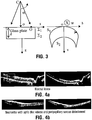
Fig. 3 shows the distorted image of a microscope slide when scanned with a fan of rays. -
Figures 4a and 4b illustrate the bending images of the retina upwards to compensate for fan scanning distortion. The image in the square centred on the fovea of the normal subject is used in the processing of the RPE layer as described below. -
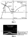
Figure 5 shows the evaluation of the refraction angle at the interface between the vitreous and the retina. -
Figure 6 is an exaggerated representation of the distortion of the RPE contour. - OCT can be implemented, for example, with apparatus described in detail in
US Patent no. 5,975,697 . The described processing can be carried out with a personal computer, for example, including a Pentium™ microprocessor. - The invention will be described with reference to the eye, although it will be understood that it could be applied to other objects having similar structure.
- Consider the case of angular OCT scanning of the eye, where the fan of rays converges in a point C, as illustrated in
Fig. 2 . This is the scanning pattern when imaging the retina. A collimated beam is scanned angularly through the anterior part of the eye, where refractive elements focus it on the retina. The top part ofFig. 2 shows the fan of rays scanning the retina The bottom part represents the image acquired by the OCT for arc circles with the center in C. Polar coordinates, r, a and a corresponding Cartesian system with axes x and z are defined for the object space with the center located in the eye pupil, C. For the image space, a simple Cartesian coordinate system (h,v) is used. The relation between a point in the object space O(r, a) and the corresponding point in the image space I(h,v) needs to be understood. - The frame grabber of the OCT system places the B-scan image in the plane (h,v), where:


- The axial scanner varies the reference path to select points within the retina, situated at a certain radial distance between r0 and r0+Δr. If the scanner moves by z, then the coherence gated spatial window advances from the initial position r0 to:

- Placing the reference for OPD = 0 in the top centre of the image o and also making the object space and the image space coincide in this point, lateral and vertical errors produced by the fan scanning can be computed as:

- E1 measures how much the image point I moves laterally relative to the corresponding object point O, while Ea signifies how much the image point I moves axially from the corresponding object point O. For a null α angle, the errors are zero.
- To better understand the distortions in the fan scanning case, let us consider a simple rectangular object, such as a microscope slide glass in
Fig. 3 left. During scanning, for a certain fixed OPD in the OCT apparatus, the coherence gate selects those points from the object situated on an arc of circle with the centre in C and radius matching the reference arm length. Under these circumstances, the anterior surface Σ1 appears in the image (Fig. 3 right) as a curved line, S1. The same is true for the other surface, Σ2 whose image is described by S2. The example inFig. 3 shows that an horizontal shape of the object surface is represented as a downward curved surface in the image space. This means that the images collected by fan scanning type have to be corrected by curving them up. - For points on the anterior surface, Σ1, the polar coordinates in the object space are:

- In Cartesian coordinates h and v, the points of the anterior surface Σ1 will be located in the B-scan image at points:

- These equations show that the higher the angle α either side of the axis oz, the larger the vertical distortion of the image. A horizontal line in the object is represented as a downwardly curved line in the image space. Similarly, the second surface, Σ2, given by points


Fig. 4 . - We inversed equations of type 6 and 8 written for each point in the image to correct T-scan based B-scan images obtained from the retina. The correction exercise is exemplifies on two images shown in
Figs. 4a and 4b , that of a normal eye and of a case of neuroretinitis with optic disc edema and peripapillary serous detachment of the neurosensory retina. To correct the images, we used an average eye length of 24 mm for a normal subject, the experimental angular span of 350 and an average index of refraction n = 1.38 as presented in literature, as for example in E. Chen, Eye Laboratory, Ophthalmic Res., 25, (1993), 65-68 and in M.Hammer, D.Schweitzer, E.Thamm, A.Kolb, "Optical Properties of ocular fundus tissues determined by optical coherence tomography", Opt. Commun., 186, 149-153, 2000. - It is important to associate the pathology location to the eye curvature, which is correct in the images bent upwards. For the numerical values used, the axial error is 1.2 mm and lateral error 0.44 mm. Although it is possible to estimate the eye length, for more accurate results, OCT should be first used to evaluate the eye length value, and input to the evaluations above.
- A second aspect of the disclosure is the correction of orientation of layers just below the foveal pit. These layers are important for correct diagnosis of eye diseases.
- A B-scan OCT image of the fovea obtained with T-scanning is shown in
Fig. 4a top left. Let us select a small lateral size image around the fovea as that inside the square superposed on the image. The lateral size is small and for simplicity, we choose to ignore here the distortion due to fan scanning presented previously. Due to the cumulated effect of (i) different indexes of refraction of the vitreous and of the retina and (ii) of the foveal depression, the image of the deep layers in the retina is distorted. For instance, an histological image of the fovea shows that the retinal pigment epithelium (RPE) is a straight oriented layer. However, due to the effects mentioned above, the RPE layer is slightly curved upwards. It is the scope of the present invention to evaluate quantitatively the distortion of the shape of the RPE layer and its upward deviation from a straight line. Let us consider the index of refraction of the vitreous, nv= 1.336, and of the retina up to the RPE, nr= 1.35. - The OCT image sampled by the square in
Fig. 4a top left could be transferred to a calibrated chart containing orthogonal co-ordinate systems (ox to the right, oz downwards) or digitally sampled. The contours of the foveal pit can then be approximated by analytical curves:
- In the same system of coordinates, the equation of the middle of the RPE can be approximated by:

- The ray coming from the vitreous is incident on the retina in Aj. The equation of the refracted line AjBj is written for a point Aj(xj,zj) on the inner limiting membrane (ILM) described by equation (19), as:

- The slope is:

- The incidence angle, θj is


- We can calculate the coordinate of each point Bj on the RPE where the line described by the equation (21) intersects the RPE described by equation (20), and obtain the points of coordinates (xp,zp). If the origin of the optical path length in the vitreous is at a coordinate z = z0 (a reference line is shown in
Fig. 5 ), then the optical path length can be evaluated as:
- This determines the shape of the RPE layer in
Fig. 6 . The deviation of the RPE layer from straight line is small and therefore, to illustrate the distortion, the bottom part below the broken line inFig. 6 is represented at a vertical scale multiplied 10 times. - In points such as Bf and Bp, where the ray comes along the normal to the retina (like points in the center, Af or outside the fovea region, AR respectively), the x coordinates are the same and the optical path length is:


- The elevation of the RPE in the center of the image can be simply calculated by subtracting equation (26a) from (26b) which gives:

- Considering a normal average foveal pit value H = (zf - zR ) = 150 µm and the values for the indexes of refraction of the vitreous, nv=1.336, and of the retina up to the RPE, nr= 1.35, δ = 2.1 µm. Such a deviation is hard to be noticed in
Fig. 5 due to the resolution, 12 µm of an SLD based OCT system. However, this deviation is comparable to the depth resolution achievable in high resolution OCT imaging of the fovea.
Claims (4)
- A method of creating OCT cross sectional images of the retinal pigment epithelium of an eye under examination, comprising:determining the length of the eye;scanning the retinal pigment epithelium, RPE, with an OCT light beam in a fan configuration from a convergence point in the pupil to create an array of image points defined by Cartesian coordinates (h,v) in an image space;transforming said array of image points in said image space to an array of points defined by polar coordinates (r,α) from said convergence point in an object space taking into account the length of the eye and the refractive index within the retina, n;wherein the polar coordinates and the Cartesian coordinates are related by:


 said image points being further transformed taking into account the foveal pit height, zf - zR, and the index of refraction of the vitreous, nv, and the average index of refraction of the fovea, nr and wherein the point on the RPE in the center of the fovea is lowered by δ = (nr - nv)(zf - zR) and all points either side are lowered by proportionally less value as the lateral distance up to an axis perpendicular on the fovea through the foveal pit;displaying said array of points in the object space on a display device to provide an OCT cross sectional image of the retina.
 - A method as claimed in claim 1, wherein the length of the eye is measured with an OCT apparatus.
- A method as claimed in claim 1, wherein the length of the eye is estimated.
- A method as claimed in claim 1 wherein the foveal pit height H is evaluated using OCT and the indexes of refraction are nv = 1.336, and of the retina up to the RPE, nr = 1.35.
Applications Claiming Priority (2)
| Application Number | Priority Date | Filing Date | Title |
|---|---|---|---|
| GB0405416A GB2412030A (en) | 2004-03-11 | 2004-03-11 | Image correction in optical coherence tomography |
| PCT/CA2005/000367 WO2005087088A1 (en) | 2004-03-11 | 2005-03-11 | Method and apparatus for displaying oct cross sections |
Publications (3)
| Publication Number | Publication Date |
|---|---|
| EP1725162A1 EP1725162A1 (en) | 2006-11-29 |
| EP1725162A4 EP1725162A4 (en) | 2010-01-13 |
| EP1725162B1 true EP1725162B1 (en) | 2017-04-19 |
Family
ID=32117424
Family Applications (1)
| Application Number | Title | Priority Date | Filing Date |
|---|---|---|---|
| EP05714607.8A Expired - Lifetime EP1725162B1 (en) | 2004-03-11 | 2005-03-11 | Method and apparatus for displaying oct cross sections |
Country Status (6)
| Country | Link |
|---|---|
| US (1) | US7594730B2 (en) |
| EP (1) | EP1725162B1 (en) |
| DK (1) | DK1725162T3 (en) |
| ES (1) | ES2633915T3 (en) |
| GB (1) | GB2412030A (en) |
| WO (1) | WO2005087088A1 (en) |
Families Citing this family (17)
| Publication number | Priority date | Publication date | Assignee | Title |
|---|---|---|---|---|
| US8223143B2 (en) | 2006-10-27 | 2012-07-17 | Carl Zeiss Meditec, Inc. | User interface for efficiently displaying relevant OCT imaging data |
| US8693745B2 (en) * | 2009-05-04 | 2014-04-08 | Duke University | Methods and computer program products for quantitative three-dimensional image correction and clinical parameter computation in optical coherence tomography |
| JP6105852B2 (en) | 2012-04-04 | 2017-03-29 | キヤノン株式会社 | Image processing apparatus and method, and program |
| WO2013188885A1 (en) * | 2012-06-15 | 2013-12-19 | Oregon Health & Science University | Non-invasive 3d imaging and measuring of anterior chamber angle of the eye |
| CN104146681B (en) * | 2014-08-15 | 2015-11-18 | 深圳市斯尔顿科技有限公司 | A kind of eye ground OCT method for correcting image |
| EP3376939B1 (en) * | 2015-11-18 | 2022-05-11 | University Of Louisville Research Foundation, Inc. | Automated methods for the objective quantification of retinal characteristics by retinal region and diagnosis of retinal pathology |
| CA3048197A1 (en) | 2016-12-21 | 2018-06-28 | Acucela Inc. | Miniaturized mobile, low cost optical coherence tomography system for home based ophthalmic applications |
| JP6987522B2 (en) * | 2017-04-10 | 2022-01-05 | キヤノン株式会社 | Image generator, image generation method, and program |
| CN118576146A (en) | 2018-06-20 | 2024-09-03 | 奥克塞拉有限公司 | A miniature, mobile, low-cost optical coherence tomography system for home-based ophthalmic applications |
| GB201916825D0 (en) * | 2019-11-19 | 2020-01-01 | Univ Of Kent | Optical coherence tomography (OCT) apparatus and OCT method |
| US11730363B2 (en) | 2019-12-26 | 2023-08-22 | Acucela Inc. | Optical coherence tomography patient alignment system for home based ophthalmic applications |
| EP3901567A1 (en) * | 2020-04-22 | 2021-10-27 | Zumbach Electronic Ag | Method and device for equalizing coherence tomography images |
| US10959613B1 (en) | 2020-08-04 | 2021-03-30 | Acucela Inc. | Scan pattern and signal processing for optical coherence tomography |
| WO2022035809A1 (en) | 2020-08-14 | 2022-02-17 | Acucela Inc. | System and method for optical coherence tomography a-scan decurving |
| US11393094B2 (en) | 2020-09-11 | 2022-07-19 | Acucela Inc. | Artificial intelligence for evaluation of optical coherence tomography images |
| JP2023544704A (en) | 2020-09-30 | 2023-10-25 | アキュセラ インコーポレイテッド | Myopia prediction, diagnosis, planning, and monitoring devices |
| WO2022204622A1 (en) | 2021-03-24 | 2022-09-29 | Acucela Inc. | Axial length measurement monitor |
Family Cites Families (7)
| Publication number | Priority date | Publication date | Assignee | Title |
|---|---|---|---|---|
| US5384608A (en) * | 1991-10-10 | 1995-01-24 | Computed Anatomy Inc. | Method for displaying corneal topography |
| US5310764A (en) * | 1992-05-08 | 1994-05-10 | Steven Baranowitz | Treatment of age related macular degeneration with beta-carotene |
| US5975697A (en) | 1998-11-25 | 1999-11-02 | Oti Ophthalmic Technologies, Inc. | Optical mapping apparatus with adjustable depth resolution |
| AU2002324605A1 (en) * | 2001-08-03 | 2003-02-17 | Joseph A Izatt | Real-time imaging system and method |
| CA2390072C (en) * | 2002-06-28 | 2018-02-27 | Adrian Gh Podoleanu | Optical mapping apparatus with adjustable depth resolution and multiple functionality |
| US7072047B2 (en) * | 2002-07-12 | 2006-07-04 | Case Western Reserve University | Method and system for quantitative image correction for optical coherence tomography |
| EP1986581B1 (en) * | 2006-01-31 | 2012-10-03 | Regents of the University of Minnesota | Surgical support structure |
-
2004
- 2004-03-11 GB GB0405416A patent/GB2412030A/en not_active Withdrawn
-
2005
- 2005-03-11 US US11/547,922 patent/US7594730B2/en not_active Expired - Lifetime
- 2005-03-11 EP EP05714607.8A patent/EP1725162B1/en not_active Expired - Lifetime
- 2005-03-11 ES ES05714607.8T patent/ES2633915T3/en not_active Expired - Lifetime
- 2005-03-11 DK DK05714607.8T patent/DK1725162T3/en active
- 2005-03-11 WO PCT/CA2005/000367 patent/WO2005087088A1/en not_active Ceased
Non-Patent Citations (1)
| Title |
|---|
| PODOLEANU A ET AL: "Correction of distortions in optical coherence tomography imaging of the eye", PHYSICS IN MEDICINE AND BIOLOGY IOP PUBLISHING UK, vol. 49, no. 7, 7 April 2004 (2004-04-07), pages 1277 - 1294, ISSN: 0031-9155 * |
Also Published As
| Publication number | Publication date |
|---|---|
| EP1725162A4 (en) | 2010-01-13 |
| DK1725162T3 (en) | 2017-08-14 |
| EP1725162A1 (en) | 2006-11-29 |
| ES2633915T3 (en) | 2017-09-26 |
| US20080074617A1 (en) | 2008-03-27 |
| WO2005087088A1 (en) | 2005-09-22 |
| US7594730B2 (en) | 2009-09-29 |
| GB2412030A (en) | 2005-09-14 |
| GB0405416D0 (en) | 2004-04-21 |
Similar Documents
| Publication | Publication Date | Title |
|---|---|---|
| Podoleanu et al. | Correction of distortions in optical coherence tomography imaging of the eye | |
| US7594730B2 (en) | Method and apparatus for displaying OCT cross sections | |
| Hitzenberger et al. | Three-dimensional imaging of the human retina by high-speed optical coherence tomography | |
| EP2612589B1 (en) | Enhanced optical coherence tomography for anatomical mapping | |
| US7878651B2 (en) | Refractive prescription using optical coherence tomography | |
| Ortiz et al. | Corneal topography from spectral optical coherence tomography (sOCT) | |
| CN102599882B (en) | Optical coherence tomographic imaging method and apparatus | |
| Karnowski et al. | Corneal topography with high-speed swept source OCT in clinical examination | |
| Rogers et al. | Topography and volume measurements of the optic nerve using en-face optical coherence tomography | |
| US20150150447A1 (en) | Non-invasive 3d imaging and measuring of anterior chamber angle of the eye | |
| Szkulmowski et al. | Analysis of posterior retinal layers in spectral optical coherence tomography images of the normal retina and retinal pathologies | |
| Shen et al. | Extended scan depth optical coherence tomography for evaluating ocular surface shape | |
| JP7286422B2 (en) | Ophthalmic information processing device, ophthalmic device, ophthalmic information processing method, and program | |
| Li et al. | Simultaneous optical coherence tomography and Scheimpflug imaging using the same incident light | |
| JP7248467B2 (en) | Ophthalmic information processing device, ophthalmic device, ophthalmic information processing method, and program | |
| JP5893248B2 (en) | Optical tomographic imaging method and optical tomographic imaging apparatus | |
| JP7194177B2 (en) | Phase-sensitive optical coherence tomography for measuring optical aberrations in the anterior segment | |
| Plesea et al. | Direct corneal elevation measurements using multiple delay en face optical coherence tomography | |
| JP7796819B2 (en) | Systems and methods for improving scleral promontory visibility in anterior segment OCT images | |
| Wehbe et al. | Automatic retinal blood vessel parameters calculation in spectral domain optical coherence tomography | |
| Podoleanu | Topography and volume measurements of the optic nerve usingen-face optical coherence tomography | |
| Podoleanu et al. | En face optical coherence tomography | |
| Rosen et al. | Multiplanar OCT/confocal ophthalmoscope in the clinic |
Legal Events
| Date | Code | Title | Description |
|---|---|---|---|
| PUAI | Public reference made under article 153(3) epc to a published international application that has entered the european phase |
Free format text: ORIGINAL CODE: 0009012 |
|
| 17P | Request for examination filed |
Effective date: 20061006 |
|
| AK | Designated contracting states |
Kind code of ref document: A1 Designated state(s): AT BE BG CH CY CZ DE DK EE ES FI FR GB GR HU IE IS IT LI LT LU MC NL PL PT RO SE SI SK TR |
|
| DAX | Request for extension of the european patent (deleted) | ||
| A4 | Supplementary search report drawn up and despatched |
Effective date: 20091215 |
|
| RIC1 | Information provided on ipc code assigned before grant |
Ipc: A61B 3/12 20060101ALI20091209BHEP Ipc: A61B 5/00 20060101ALI20091209BHEP Ipc: A61B 3/14 20060101AFI20050927BHEP Ipc: G06T 3/00 20060101ALI20091209BHEP |
|
| 17Q | First examination report despatched |
Effective date: 20120928 |
|
| RAP1 | Party data changed (applicant data changed or rights of an application transferred) |
Owner name: OPTOS PLC |
|
| GRAP | Despatch of communication of intention to grant a patent |
Free format text: ORIGINAL CODE: EPIDOSNIGR1 |
|
| INTG | Intention to grant announced |
Effective date: 20160920 |
|
| GRAJ | Information related to disapproval of communication of intention to grant by the applicant or resumption of examination proceedings by the epo deleted |
Free format text: ORIGINAL CODE: EPIDOSDIGR1 |
|
| STAA | Information on the status of an ep patent application or granted ep patent |
Free format text: STATUS: EXAMINATION IS IN PROGRESS |
|
| INTC | Intention to grant announced (deleted) | ||
| GRAR | Information related to intention to grant a patent recorded |
Free format text: ORIGINAL CODE: EPIDOSNIGR71 |
|
| GRAS | Grant fee paid |
Free format text: ORIGINAL CODE: EPIDOSNIGR3 |
|
| STAA | Information on the status of an ep patent application or granted ep patent |
Free format text: STATUS: GRANT OF PATENT IS INTENDED |
|
| GRAA | (expected) grant |
Free format text: ORIGINAL CODE: 0009210 |
|
| STAA | Information on the status of an ep patent application or granted ep patent |
Free format text: STATUS: THE PATENT HAS BEEN GRANTED |
|
| AK | Designated contracting states |
Kind code of ref document: B1 Designated state(s): AT BE BG CH CY CZ DE DK EE ES FI FR GB GR HU IE IS IT LI LT LU MC NL PL PT RO SE SI SK TR |
|
| INTG | Intention to grant announced |
Effective date: 20170310 |
|
| REG | Reference to a national code |
Ref country code: GB Ref legal event code: FG4D |
|
| REG | Reference to a national code |
Ref country code: CH Ref legal event code: EP |
|
| REG | Reference to a national code |
Ref country code: AT Ref legal event code: REF Ref document number: 885116 Country of ref document: AT Kind code of ref document: T Effective date: 20170515 |
|
| REG | Reference to a national code |
Ref country code: IE Ref legal event code: FG4D |
|
| REG | Reference to a national code |
Ref country code: DE Ref legal event code: R096 Ref document number: 602005051770 Country of ref document: DE |
|
| REG | Reference to a national code |
Ref country code: CH Ref legal event code: NV Representative=s name: SERVOPATENT GMBH, CH |
|
| REG | Reference to a national code |
Ref country code: NL Ref legal event code: FP |
|
| REG | Reference to a national code |
Ref country code: SE Ref legal event code: TRGR |
|
| REG | Reference to a national code |
Ref country code: DK Ref legal event code: T3 Effective date: 20170811 |
|
| REG | Reference to a national code |
Ref country code: LT Ref legal event code: MG4D |
|
| REG | Reference to a national code |
Ref country code: ES Ref legal event code: FG2A Ref document number: 2633915 Country of ref document: ES Kind code of ref document: T3 Effective date: 20170926 |
|
| PG25 | Lapsed in a contracting state [announced via postgrant information from national office to epo] |
Ref country code: GR Free format text: LAPSE BECAUSE OF FAILURE TO SUBMIT A TRANSLATION OF THE DESCRIPTION OR TO PAY THE FEE WITHIN THE PRESCRIBED TIME-LIMIT Effective date: 20170720 Ref country code: LT Free format text: LAPSE BECAUSE OF FAILURE TO SUBMIT A TRANSLATION OF THE DESCRIPTION OR TO PAY THE FEE WITHIN THE PRESCRIBED TIME-LIMIT Effective date: 20170419 |
|
| PG25 | Lapsed in a contracting state [announced via postgrant information from national office to epo] |
Ref country code: PL Free format text: LAPSE BECAUSE OF FAILURE TO SUBMIT A TRANSLATION OF THE DESCRIPTION OR TO PAY THE FEE WITHIN THE PRESCRIBED TIME-LIMIT Effective date: 20170419 Ref country code: BG Free format text: LAPSE BECAUSE OF FAILURE TO SUBMIT A TRANSLATION OF THE DESCRIPTION OR TO PAY THE FEE WITHIN THE PRESCRIBED TIME-LIMIT Effective date: 20170719 Ref country code: IS Free format text: LAPSE BECAUSE OF FAILURE TO SUBMIT A TRANSLATION OF THE DESCRIPTION OR TO PAY THE FEE WITHIN THE PRESCRIBED TIME-LIMIT Effective date: 20170819 |
|
| REG | Reference to a national code |
Ref country code: DE Ref legal event code: R097 Ref document number: 602005051770 Country of ref document: DE |
|
| PG25 | Lapsed in a contracting state [announced via postgrant information from national office to epo] |
Ref country code: SK Free format text: LAPSE BECAUSE OF FAILURE TO SUBMIT A TRANSLATION OF THE DESCRIPTION OR TO PAY THE FEE WITHIN THE PRESCRIBED TIME-LIMIT Effective date: 20170419 Ref country code: EE Free format text: LAPSE BECAUSE OF FAILURE TO SUBMIT A TRANSLATION OF THE DESCRIPTION OR TO PAY THE FEE WITHIN THE PRESCRIBED TIME-LIMIT Effective date: 20170419 Ref country code: RO Free format text: LAPSE BECAUSE OF FAILURE TO SUBMIT A TRANSLATION OF THE DESCRIPTION OR TO PAY THE FEE WITHIN THE PRESCRIBED TIME-LIMIT Effective date: 20170419 Ref country code: CZ Free format text: LAPSE BECAUSE OF FAILURE TO SUBMIT A TRANSLATION OF THE DESCRIPTION OR TO PAY THE FEE WITHIN THE PRESCRIBED TIME-LIMIT Effective date: 20170419 |
|
| PLBE | No opposition filed within time limit |
Free format text: ORIGINAL CODE: 0009261 |
|
| STAA | Information on the status of an ep patent application or granted ep patent |
Free format text: STATUS: NO OPPOSITION FILED WITHIN TIME LIMIT |
|
| REG | Reference to a national code |
Ref country code: FR Ref legal event code: PLFP Year of fee payment: 14 |
|
| 26N | No opposition filed |
Effective date: 20180122 |
|
| PG25 | Lapsed in a contracting state [announced via postgrant information from national office to epo] |
Ref country code: SI Free format text: LAPSE BECAUSE OF FAILURE TO SUBMIT A TRANSLATION OF THE DESCRIPTION OR TO PAY THE FEE WITHIN THE PRESCRIBED TIME-LIMIT Effective date: 20170419 |
|
| PG25 | Lapsed in a contracting state [announced via postgrant information from national office to epo] |
Ref country code: MC Free format text: LAPSE BECAUSE OF FAILURE TO SUBMIT A TRANSLATION OF THE DESCRIPTION OR TO PAY THE FEE WITHIN THE PRESCRIBED TIME-LIMIT Effective date: 20170419 |
|
| REG | Reference to a national code |
Ref country code: IE Ref legal event code: MM4A |
|
| PG25 | Lapsed in a contracting state [announced via postgrant information from national office to epo] |
Ref country code: LU Free format text: LAPSE BECAUSE OF NON-PAYMENT OF DUE FEES Effective date: 20180311 |
|
| PG25 | Lapsed in a contracting state [announced via postgrant information from national office to epo] |
Ref country code: IE Free format text: LAPSE BECAUSE OF NON-PAYMENT OF DUE FEES Effective date: 20180311 |
|
| REG | Reference to a national code |
Ref country code: AT Ref legal event code: UEP Ref document number: 885116 Country of ref document: AT Kind code of ref document: T Effective date: 20170419 |
|
| PG25 | Lapsed in a contracting state [announced via postgrant information from national office to epo] |
Ref country code: TR Free format text: LAPSE BECAUSE OF FAILURE TO SUBMIT A TRANSLATION OF THE DESCRIPTION OR TO PAY THE FEE WITHIN THE PRESCRIBED TIME-LIMIT Effective date: 20170419 |
|
| PG25 | Lapsed in a contracting state [announced via postgrant information from national office to epo] |
Ref country code: HU Free format text: LAPSE BECAUSE OF FAILURE TO SUBMIT A TRANSLATION OF THE DESCRIPTION OR TO PAY THE FEE WITHIN THE PRESCRIBED TIME-LIMIT; INVALID AB INITIO Effective date: 20050311 Ref country code: PT Free format text: LAPSE BECAUSE OF FAILURE TO SUBMIT A TRANSLATION OF THE DESCRIPTION OR TO PAY THE FEE WITHIN THE PRESCRIBED TIME-LIMIT Effective date: 20170419 |
|
| REG | Reference to a national code |
Ref country code: CH Ref legal event code: PCAR Free format text: NEW ADDRESS: WANNERSTRASSE 9/1, 8045 ZUERICH (CH) |
|
| PG25 | Lapsed in a contracting state [announced via postgrant information from national office to epo] |
Ref country code: CY Free format text: LAPSE BECAUSE OF FAILURE TO SUBMIT A TRANSLATION OF THE DESCRIPTION OR TO PAY THE FEE WITHIN THE PRESCRIBED TIME-LIMIT Effective date: 20170419 |
|
| P01 | Opt-out of the competence of the unified patent court (upc) registered |
Effective date: 20230512 |
|
| PGFP | Annual fee paid to national office [announced via postgrant information from national office to epo] |
Ref country code: NL Payment date: 20240311 Year of fee payment: 20 |
|
| PGFP | Annual fee paid to national office [announced via postgrant information from national office to epo] |
Ref country code: AT Payment date: 20240306 Year of fee payment: 20 |
|
| PGFP | Annual fee paid to national office [announced via postgrant information from national office to epo] |
Ref country code: FI Payment date: 20240306 Year of fee payment: 20 Ref country code: DE Payment date: 20240306 Year of fee payment: 20 Ref country code: GB Payment date: 20240315 Year of fee payment: 20 |
|
| PGFP | Annual fee paid to national office [announced via postgrant information from national office to epo] |
Ref country code: SE Payment date: 20240314 Year of fee payment: 20 Ref country code: IT Payment date: 20240304 Year of fee payment: 20 Ref country code: FR Payment date: 20240307 Year of fee payment: 20 Ref country code: DK Payment date: 20240312 Year of fee payment: 20 Ref country code: BE Payment date: 20240311 Year of fee payment: 20 |
|
| PGFP | Annual fee paid to national office [announced via postgrant information from national office to epo] |
Ref country code: CH Payment date: 20240401 Year of fee payment: 20 |
|
| PGFP | Annual fee paid to national office [announced via postgrant information from national office to epo] |
Ref country code: ES Payment date: 20240408 Year of fee payment: 20 |
|
| REG | Reference to a national code |
Ref country code: DE Ref legal event code: R071 Ref document number: 602005051770 Country of ref document: DE |
|
| REG | Reference to a national code |
Ref country code: NL Ref legal event code: MK Effective date: 20250310 |
|
| REG | Reference to a national code |
Ref country code: CH Ref legal event code: PL |
|
| REG | Reference to a national code |
Ref country code: DK Ref legal event code: EUP Expiry date: 20250311 |
|
| REG | Reference to a national code |
Ref country code: GB Ref legal event code: PE20 Expiry date: 20250310 |
|
| REG | Reference to a national code |
Ref country code: AT Ref legal event code: MK07 Ref document number: 885116 Country of ref document: AT Kind code of ref document: T Effective date: 20250311 |
|
| PG25 | Lapsed in a contracting state [announced via postgrant information from national office to epo] |
Ref country code: GB Free format text: LAPSE BECAUSE OF EXPIRATION OF PROTECTION Effective date: 20250310 |
|
| REG | Reference to a national code |
Ref country code: SE Ref legal event code: EUG |
|
| REG | Reference to a national code |
Ref country code: ES Ref legal event code: FD2A Effective date: 20250506 |
|
| REG | Reference to a national code |
Ref country code: BE Ref legal event code: MK Effective date: 20250311 |
|
| PG25 | Lapsed in a contracting state [announced via postgrant information from national office to epo] |
Ref country code: ES Free format text: LAPSE BECAUSE OF EXPIRATION OF PROTECTION Effective date: 20250312 |