EP1725077A2 - Microwave oven having an ultrasonic oscillator - Google Patents
Microwave oven having an ultrasonic oscillator Download PDFInfo
- Publication number
- EP1725077A2 EP1725077A2 EP06018519A EP06018519A EP1725077A2 EP 1725077 A2 EP1725077 A2 EP 1725077A2 EP 06018519 A EP06018519 A EP 06018519A EP 06018519 A EP06018519 A EP 06018519A EP 1725077 A2 EP1725077 A2 EP 1725077A2
- Authority
- EP
- European Patent Office
- Prior art keywords
- cavity
- food article
- ultrasonic oscillator
- microwave oven
- tray
- Prior art date
- Legal status (The legal status is an assumption and is not a legal conclusion. Google has not performed a legal analysis and makes no representation as to the accuracy of the status listed.)
- Withdrawn
Links
Images


Classifications
-
- F—MECHANICAL ENGINEERING; LIGHTING; HEATING; WEAPONS; BLASTING
- F24—HEATING; RANGES; VENTILATING
- F24C—DOMESTIC STOVES OR RANGES ; DETAILS OF DOMESTIC STOVES OR RANGES, OF GENERAL APPLICATION
- F24C7/00—Stoves or ranges heated by electric energy
- F24C7/04—Stoves or ranges heated by electric energy with heat radiated directly from the heating element
-
- H—ELECTRICITY
- H05—ELECTRIC TECHNIQUES NOT OTHERWISE PROVIDED FOR
- H05B—ELECTRIC HEATING; ELECTRIC LIGHT SOURCES NOT OTHERWISE PROVIDED FOR; CIRCUIT ARRANGEMENTS FOR ELECTRIC LIGHT SOURCES, IN GENERAL
- H05B6/00—Heating by electric, magnetic or electromagnetic fields
- H05B6/64—Heating using microwaves
- H05B6/6402—Aspects relating to the microwave cavity
- H05B6/6405—Self-cleaning cavity
-
- H—ELECTRICITY
- H05—ELECTRIC TECHNIQUES NOT OTHERWISE PROVIDED FOR
- H05B—ELECTRIC HEATING; ELECTRIC LIGHT SOURCES NOT OTHERWISE PROVIDED FOR; CIRCUIT ARRANGEMENTS FOR ELECTRIC LIGHT SOURCES, IN GENERAL
- H05B6/00—Heating by electric, magnetic or electromagnetic fields
- H05B6/64—Heating using microwaves
- H05B6/647—Aspects related to microwave heating combined with other heating techniques
Definitions
- the present invention relates to a heating apparatus in a microwave oven in which one of microwave oven elements, namely a tray in a cavity where a food article to be cooked is usually placed is used as a medium of an ultrasonic oscillator.
- a microwave oven cooks a food article positioned in a cooking chamber by application of heat energy from an electric heater as a heat source.
- Another auxiliary heat source, magnetron for example, is sometimes installed to use microwaves as a separate heat source.
- Fig. 1 is a schematic perspective view illustrating a main part of a related art microwave oven.
- the microwave oven includes a case 1; a cavity 2 formed inside of the case 1; a door 3 pivotably fastened to the entire low surface of the case 1 to be able to open/close the cavity 2; an operation display 5 installed at a top front surface of the cavity 2, displaying an operation state of every button needed for operation of the microwave and displaying a state of the oven; a lower heater 7 installed between a low portion of the cavity 2 and the case, providing heat through the bottom of the cavity 2; an upper heater 9 installed at an upper portion of the cavity 2, heating a food article inside the cavity with radiant heat from the heater; a convection heater 11 installed between the bottom surface of the cavity 2 and the case 1; a convection fan 13 installed at the bottom surface of the cavity 2, supplying heated air by the convection heater 11 into the cavity 2; a cooling fan 17 installed between the upper portion of the cavity 2 and the case 1, cooling electric elements; an oven lamp 18 for illuminating an inside of the cooking chamber; and a magnetron 15 for generating microwaves
- a knob 4 On the top end of the door 3 is a knob 4.
- a user wants to open the cavity 2, he or she needs to pull the knob 4 installed at the top end of the door 3. What happens then is the door is rotated by means of a hinge connecting the lower end of the case 1 with the door 3, and the closed cavity 2 is opened.
- a plurality of air passage holes 14 are perforated on the bottom surface of the cavity 2 opposed to the convection heater 11.
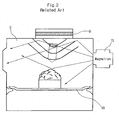
- Fig. 2 is a state diagram illustrating a food article positioned inside of the related art microwave oven's cavity being cooked by heat from a heater and by magnetron.
- heat generated from the upper heater 9, which is installed at the upper portion of the cavity 2 is transmitted to the food article through radiation and convection. Further, by operation of the convection fan 13, heat from the convection heater 11 is also transmitted in form of hot wind to the food article via the plurality of air passage holes 14 formed on the bottom surface of the cavity 2.
- the related art microwave oven poses a serious problem in its heating method.
- a part of the food article is cooked by heat from the upper heater 9 installed at the top end of the cavity 2 through radiation and convection, as shown in Fig. 2.
- the inside of the cavity 2 can have a homogenous temperature field overall.
- the heater 9 is used to cook the food article, heat is not evenly reached the inside of the food article, but only the surface area of the food article is cooked, resulting in overcooking or burning the surface of the food article.
- European Patent application EP 0 455 513 describes a microwave heating system provided with a magnetic mixer. Such a device is in fact only suited to specific applications in which liquids should be stirred.
- An object of the invention is to solve at least the above problems and/or disadvantages and to provide at least the advantages described hereinafter.
- one object of the present invention is to solve the foregoing problems by providing a heating apparatus in a microwave oven that is capable of greatly reducing cooking time, by using a metal tray inside of a cavity where a food article to be cooked is placed as a medium of ultrasonic oscillation generated from an oscillating means and by transmitting ultrasonic waves to the food article to activate molecular structures of the food article, whereby heating speed by heater applied to the food article can be uniform on both surface and inside of the food article and simultaneously, cooking time can be greatly reduced according to the uniform heating speed applied to the food article.
- a heating apparatus having a means for heating an article in a microwave oven, including: a cavity formed inside of a case of the apparatus; a tray installed inside of the cavity, on which the article to be heated is positioned; and an oscillating means connected to the tray for oscillating the tray.
- the oscillating means is in contact with the tray, and fastened at a predetermined position on the cavity by means of a fixing means.
- the oscillating means is in contact with the tray, and fastened to the case by using a bracket as a fixing means.
- the bracket and the case are fastened to each other by means of a hook-shaped suspender or a coupling of a bolt and a nut.
- heating speed applied to the food article by a heater can be uniform at the surface as well as at the inside of the food article.
- cooking time can be greatly reduced.
- Fig. 1 is a schematic perspective view illustrating a main part of a related art microwave oven
- Fig. 2 is a state diagram illustrating a food article positioned inside of a related art microwave oven's cavity being cooked by heat from a heater and by magnetron;
- Fig. 3 illustrates a detailed configuration of a cavity out of main elements of a microwave oven according to a preferred embodiment of the present invention, in which an ultrasonic oscillator is installed at the cavity;
- Fig. 4 is an operational state diagram of a microwave oven to which an ultrasonic oscillator is applied according to the present invention.
- Fig. 5 is an operational state diagram of another embodiment of a microwave oven to which an ultrasonic oscillator is applied.
- ultrasonic waves generated by an oscillating means are transmitted to a food article to be heated and activate molecular structures of the food article.
- heating speed applied to the surface and the inside of the food article is uniform, and thus, cooking time can be greatly reduced.
- Fig. 3 illustrates a detailed configuration of a cavity out of main elements of the microwave oven according to the present invention, in which an ultrasonic oscillator is installed at the cavity.
- the heating apparatus in a microwave oven of the invention includes a cavity 2 formed inside of a case; a tray 19 installed inside of the cavity 2, on which a food article is positioned; a heater 9 installed at an upper part and a lower part of the cavity 2, heating the food article inside of the cavity 2 through radiation or convection; and an ultrasonic oscillator 20 installed at a predetermined position of the cavity 2 to be in contact with the tray 19, activating molecular structures of the food article placed on the tray 19 by using ultrasonic waves.
- a bracket 21 is used to ensure that the ultrasonic oscillator 20 is firmly fastened at the predetermined outside position of the cavity 2 in contact with the tray 19.
- the bracket 21 can be fastened to the cavity 2 by means of a hook-shaped suspender 22, or a coupling of a bolt and a nut.
- the ultrasonic oscillator 20 is installed at the predetermined outside position of the cavity 2 in contact with the tray 19.
- heating speed of the food article that is, heating speed by application of heat from the heater 9, is uniform both on the surface of the food article and inside of the food article.
- microwave oven elements of the invention are identical with those in the related art microwave oven discussed before, so like numerals are used for like and corresponding parts of the various drawings.
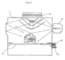
- Fig. 4 is an operational state diagram of the microwave oven to which the ultrasonic oscillator is applied according to the present invention.
- the microwave oven includes a cavity 2 formed inside of a case; a tray 19 installed inside of the cavity 2, on which a food article is positioned; a heater 9 installed at an upper part and a lower part of the cavity 2, heating the food article inside of the cavity 2 through radiation or convection; and an ultrasonic oscillator 20 installed at a predetermined position of the cavity 2 to be in contact with the tray 19, activating molecular structures of the food article placed on the tray 19 by using ultrasonic waves.
- the ultrasonic oscillator 20 oscillates ultrasonic waves having a frequency of equal to or higher than 20, 000Hz, an audibility limit.
- the ultrasonic waves are oscillated to a solid medium with a very strong molecular structure, intermolecular bonding breaks down by the ultrasonic waves, and the solid medium is destroyed.
- the ultrasonic waves are oscillated to a liquid medium that has a relatively weak intermolecular bonding, the liquid gets boiled because of free movement between molecules.
- the tray 19 inside of the cavity 2 is used as a medium of the ultrasonic oscillator 20.
- the ultrasonic oscillator 20 is installed at the predetermined outside position of the cavity 2 in contact with the tray 19.
- the ultrasonic waves oscillated from the ultrasonic oscillator 20 are transmitted to the tray 19, the medium, and eventually to the food article. These transmitted ultrasonic waves activate the molecular structures of the food article.
- the tray 19 is employed as the medium for transmission of the ultrasonic waves from the ultrasonic oscillator 20 to the food article, the molecular structures of the food article are well activated, and thus, heating speed applied to the food article is uniform on the surface and inside. As a result, cooking time can be considerably reduced.
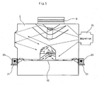
- Fig. 5 is an operational state diagram of another embodiment of the microwave oven to which the ultrasonic oscillator is applied.
- the cavity 2 transmits the ultrasonic waves to the food article placed at the tray 19, and the molecular structures of the food article are activated thereby.
- the microwave oven having the ultrasonic oscillator when a user places a food article at an inside of the cavity 2 and closes the door 3, the cavity 2 starts cooking the food article while the cavity 2 is being shut by the door 3.
- heat from the upper heater 9 installed at the upper end of the cavity 2 is transmitted to the food article through radiation and convection, and simultaneously, the ultrasonic waves from the ultrasonic oscillator 20, which is installed at the predetermined outside position of the cavity 2 in contact with the tray 19, are transmitted to the food article.
- the ultrasonic waves from the ultrasonic oscillator 20 are transmitted to the food article via the tray 19 that is used as the medium, and as a result thereof, intermolecular movements of the food article are activated.
- a magnetron 15 also oscillates microwaves. These microwaves are used as another heat source for the food article.
- the oscillating means can be formed in the case, thereby utilizing the case and the tray as the medium of the ultrasonic oscillation.
- the molecular structures of the food article are activated, and thus, heating speed applied to the food article by the heater can be uniform at the surface as well as at the inside of the food article. As the inside and the outside of the food article are heated at a uniform heating speed, cooking time can be greatly reduced.
- the oscillating mans can be formed, using the case and the tray as the medium of the ultrasonic oscillation.
- the ultrasonic oscillator 20 can also be advantageously used for users to clean the interior of the cavity. Specifically speaking, after using the microwave oven for a certain period of time, food particles stuck to the inner wall of the cavity 2 can be easily removed by the ultrasonic waves oscillated from the ultrasonic oscillator 20 because when the ultrasonic waves are transmitted, molecular structures of the food particles are activated and thus, can be easily removed.
- the heating apparatus in the microwave oven according to the present invention can also be applied to microwave ovens using a high-frequency wave as a heat source.
- the heating apparatus of the present invention can be employed to a steaming cooking system using ultrasonic waves, and a heat exchanger using ultrasonic waves to increase uniform heat transmission.
Abstract
Description
- The present invention relates to a heating apparatus in a microwave oven in which one of microwave oven elements, namely a tray in a cavity where a food article to be cooked is usually placed is used as a medium of an ultrasonic oscillator.
- In general, a microwave oven cooks a food article positioned in a cooking chamber by application of heat energy from an electric heater as a heat source. Another auxiliary heat source, magnetron for example, is sometimes installed to use microwaves as a separate heat source.
- Fig. 1 is a schematic perspective view illustrating a main part of a related art microwave oven.
- As shown in Fig. 1, the microwave oven includes a case 1; a
cavity 2 formed inside of the case 1; adoor 3 pivotably fastened to the entire low surface of the case 1 to be able to open/close thecavity 2; anoperation display 5 installed at a top front surface of thecavity 2, displaying an operation state of every button needed for operation of the microwave and displaying a state of the oven; alower heater 7 installed between a low portion of thecavity 2 and the case, providing heat through the bottom of thecavity 2; anupper heater 9 installed at an upper portion of thecavity 2, heating a food article inside the cavity with radiant heat from the heater; a convection heater 11 installed between the bottom surface of thecavity 2 and the case 1; aconvection fan 13 installed at the bottom surface of thecavity 2, supplying heated air by the convection heater 11 into thecavity 2; acooling fan 17 installed between the upper portion of thecavity 2 and the case 1, cooling electric elements; anoven lamp 18 for illuminating an inside of the cooking chamber; and amagnetron 15 for generating microwaves for cooking the food article. - On the top end of the
door 3 is a knob 4. Thus, when a user wants to open thecavity 2, he or she needs to pull the knob 4 installed at the top end of thedoor 3. What happens then is the door is rotated by means of a hinge connecting the lower end of the case 1 with thedoor 3, and the closedcavity 2 is opened. - Also, to supply heated air by the convection heater 11 into the
cavity 2 through an operation of theconvection fan 13, a plurality of air passage holes 14 are perforated on the bottom surface of thecavity 2 opposed to the convection heater 11. - Fig. 2 is a state diagram illustrating a food article positioned inside of the related art microwave oven's cavity being cooked by heat from a heater and by magnetron.
- An operation of the related art microwave oven with the above configuration is now described.
- When a user places a food article at an inside of the
cavity 2 and closes thedoor 3, thecavity 2 starts cooking the food article while thecavity 2 is being shut by thedoor 3. At this point, heat generated from thelower heater 7, which is installed between the lower portion of thecavity 2 and the case 1, is conducted to the bottom surface of thecavity 2, and the conducted heat is eventually transmitted to the food article through air circulation inside of thecavity 2 and through a tray where the food article is placed. - Moreover, heat generated from the
upper heater 9, which is installed at the upper portion of thecavity 2, is transmitted to the food article through radiation and convection. Further, by operation of theconvection fan 13, heat from the convection heater 11 is also transmitted in form of hot wind to the food article via the plurality of air passage holes 14 formed on the bottom surface of thecavity 2. - However, the related art microwave oven poses a serious problem in its heating method. For example, a part of the food article is cooked by heat from the
upper heater 9 installed at the top end of thecavity 2 through radiation and convection, as shown in Fig. 2. In this case, since an inside temperature of thecavity 2 is forcefully mixed by theconvection fan 13, the inside of thecavity 2 can have a homogenous temperature field overall. However, there is a limit to get the heat to be effectively absorbed by the food article placed at thetray 19 though the above heating method. Particularly, when theheater 9 is used to cook the food article, heat is not evenly reached the inside of the food article, but only the surface area of the food article is cooked, resulting in overcooking or burning the surface of the food article. - To prevent the surface of the food article from burning by heat from the
heater 9, manufacturers made theheater 9 to be turned on/off as needed. However, it turned out that this turning on/off method only prolonged the cooking time more than necessary.
European Patent application EP 0 455 513 describes a microwave heating system provided with a magnetic mixer. Such a device is in fact only suited to specific applications in which liquids should be stirred. - An object of the invention is to solve at least the above problems and/or disadvantages and to provide at least the advantages described hereinafter.
- Accordingly, one object of the present invention is to solve the foregoing problems by providing a heating apparatus in a microwave oven that is capable of greatly reducing cooking time, by using a metal tray inside of a cavity where a food article to be cooked is placed as a medium of ultrasonic oscillation generated from an oscillating means and by transmitting ultrasonic waves to the food article to activate molecular structures of the food article, whereby heating speed by heater applied to the food article can be uniform on both surface and inside of the food article and simultaneously, cooking time can be greatly reduced according to the uniform heating speed applied to the food article.
- The foregoing and other objects and advantages are realized by providing a heating apparatus having a means for heating an article in a microwave oven, including: a cavity formed inside of a case of the apparatus; a tray installed inside of the cavity, on which the article to be heated is positioned; and an oscillating means connected to the tray for oscillating the tray.
- In an embodiment of the invention, the oscillating means is in contact with the tray, and fastened at a predetermined position on the cavity by means of a fixing means.
- In an embodiment of the invention, the oscillating means is in contact with the tray, and fastened to the case by using a bracket as a fixing means.
- In an embodiment of the invention, the bracket and the case are fastened to each other by means of a hook-shaped suspender or a coupling of a bolt and a nut.
- According to the invention, by using a food article-holding tray inside of the cavity as the medium of an ultrasonic oscillator, molecular structures of a food article are activated, and thus, heating speed applied to the food article by a heater can be uniform at the surface as well as at the inside of the food article. As the inside and the outside of the food article are heated at a uniform heating speed, cooking time can be greatly reduced.
- Additional advantages, objects, and features of the invention will be set forth in part in the description which follows and in part will become apparent to those having ordinary skill in the art upon examination of the following or may be learned from practice of the invention. The objects and advantages of the invention may be realized and attained as particularly pointed out in the appended claims.
- The invention will be described in detail with reference to the following drawings in which like reference numerals refer to like elements wherein:
- Fig. 1 is a schematic perspective view illustrating a main part of a related art microwave oven;
- Fig. 2 is a state diagram illustrating a food article positioned inside of a related art microwave oven's cavity being cooked by heat from a heater and by magnetron;
- Fig. 3 illustrates a detailed configuration of a cavity out of main elements of a microwave oven according to a preferred embodiment of the present invention, in which an ultrasonic oscillator is installed at the cavity;
- Fig. 4 is an operational state diagram of a microwave oven to which an ultrasonic oscillator is applied according to the present invention; and
- Fig. 5 is an operational state diagram of another embodiment of a microwave oven to which an ultrasonic oscillator is applied.
- The following detailed description will present a heating apparatus in a microwave oven according to a preferred embodiment of the invention in reference to the accompanying drawings.
- According to the heating apparatus in a microwave oven of the present invention, ultrasonic waves generated by an oscillating means are transmitted to a food article to be heated and activate molecular structures of the food article. Using heat from a heater and a magnetron, heating speed applied to the surface and the inside of the food article is uniform, and thus, cooking time can be greatly reduced.
- Fig. 3 illustrates a detailed configuration of a cavity out of main elements of the microwave oven according to the present invention, in which an ultrasonic oscillator is installed at the cavity.
- Referring to Fig. 3, the heating apparatus in a microwave oven of the invention includes a
cavity 2 formed inside of a case; atray 19 installed inside of thecavity 2, on which a food article is positioned; aheater 9 installed at an upper part and a lower part of thecavity 2, heating the food article inside of thecavity 2 through radiation or convection; and anultrasonic oscillator 20 installed at a predetermined position of thecavity 2 to be in contact with thetray 19, activating molecular structures of the food article placed on thetray 19 by using ultrasonic waves. - As shown in Fig. 3, a
bracket 21 is used to ensure that theultrasonic oscillator 20 is firmly fastened at the predetermined outside position of thecavity 2 in contact with thetray 19. Here, thebracket 21 can be fastened to thecavity 2 by means of a hook-shaped suspender 22, or a coupling of a bolt and a nut. - More details on the heating apparatus in the microwave oven of the present invention are now provided.
- Using the
tray 19 inside of thecavity 2 where the food article is positioned as a medium of theultrasonic oscillator 20, ultrasonic waves from theultrasonic oscillator 20 are transmitted to the food article. Specifically, theultrasonic oscillator 20 is installed at the predetermined outside position of thecavity 2 in contact with thetray 19. As a result, molecular structures of the food article are activated, and at the same time, heating speed of the food article, that is, heating speed by application of heat from theheater 9, is uniform both on the surface of the food article and inside of the food article. - The microwave oven elements of the invention are identical with those in the related art microwave oven discussed before, so like numerals are used for like and corresponding parts of the various drawings.
- Therefore, detailed description of the invention will mainly be focused on the heating apparatus in the microwave oven having an oscillating means.
- Fig. 4 is an operational state diagram of the microwave oven to which the ultrasonic oscillator is applied according to the present invention.
- As shown in Fig. 4, the microwave oven includes a
cavity 2 formed inside of a case; atray 19 installed inside of thecavity 2, on which a food article is positioned; aheater 9 installed at an upper part and a lower part of thecavity 2, heating the food article inside of thecavity 2 through radiation or convection; and anultrasonic oscillator 20 installed at a predetermined position of thecavity 2 to be in contact with thetray 19, activating molecular structures of the food article placed on thetray 19 by using ultrasonic waves. - Particularly, the
ultrasonic oscillator 20 oscillates ultrasonic waves having a frequency of equal to or higher than 20, 000Hz, an audibility limit. When the ultrasonic waves are oscillated to a solid medium with a very strong molecular structure, intermolecular bonding breaks down by the ultrasonic waves, and the solid medium is destroyed. On the other hand, when the ultrasonic waves are oscillated to a liquid medium that has a relatively weak intermolecular bonding, the liquid gets boiled because of free movement between molecules. - To activate the molecular structures of the food article inside of the
cavity 2 by using the ultrasonic waves, and at the same time, to heat the surface of the food article as well as the inside of the food article uniformly by using heat from theheater 9, thetray 19 inside of thecavity 2 is used as a medium of theultrasonic oscillator 20. To this end, theultrasonic oscillator 20 is installed at the predetermined outside position of thecavity 2 in contact with thetray 19. The ultrasonic waves oscillated from theultrasonic oscillator 20 are transmitted to thetray 19, the medium, and eventually to the food article. These transmitted ultrasonic waves activate the molecular structures of the food article. - Moreover, because the
tray 19 is employed as the medium for transmission of the ultrasonic waves from theultrasonic oscillator 20 to the food article, the molecular structures of the food article are well activated, and thus, heating speed applied to the food article is uniform on the surface and inside. As a result, cooking time can be considerably reduced. - Fig. 5 is an operational state diagram of another embodiment of the microwave oven to which the ultrasonic oscillator is applied.
- As illustrated in Fig. 5, when the
ultrasonic oscillator 20 is installed at any position of the top and bottom/right and left side of thecavity 2, thecavity 2 itself is used as a medium of theultrasonic oscillator 20. Therefore, thecavity 2 transmits the ultrasonic waves to the food article placed at thetray 19, and the molecular structures of the food article are activated thereby. - Now, as for the operation of the microwave oven having the ultrasonic oscillator, when a user places a food article at an inside of the
cavity 2 and closes thedoor 3, thecavity 2 starts cooking the food article while thecavity 2 is being shut by thedoor 3. At this point, heat from theupper heater 9 installed at the upper end of thecavity 2 is transmitted to the food article through radiation and convection, and simultaneously, the ultrasonic waves from theultrasonic oscillator 20, which is installed at the predetermined outside position of thecavity 2 in contact with thetray 19, are transmitted to the food article. Especially, the ultrasonic waves from theultrasonic oscillator 20 are transmitted to the food article via thetray 19 that is used as the medium, and as a result thereof, intermolecular movements of the food article are activated. This in turn activates heat transmission into the food article. When theheater 9 is used to heating the food article while allowing the ultrasonic waves oscillated from theultrasonic oscillator 20 to activate the molecular structures of the food article, amagnetron 15 also oscillates microwaves. These microwaves are used as another heat source for the food article. - Accordingly, when heat transmission to the food article is increased by activated intermolecular movements of the food article, not only the surface of the food article but also the inside of the food article can be uniformly heated by the
heater 9. In this manner, the problem found in the related art heating method of the microwave oven, i.e. burning the surface of the food particle, can be resolved. - As for another embodiment, the oscillating means can be formed in the case, thereby utilizing the case and the tray as the medium of the ultrasonic oscillation.
- In conclusion, by using the food article-holding tray inside of the cavity as the medium of the ultrasonic oscillator, the molecular structures of the food article are activated, and thus, heating speed applied to the food article by the heater can be uniform at the surface as well as at the inside of the food article. As the inside and the outside of the food article are heated at a uniform heating speed, cooking time can be greatly reduced.
- While the invention has been shown and described with reference to certain preferred embodiments thereof, it will be understood by those skilled in the art that various changes in form and details may be made therein without departing from the spirit and scope of the invention as defined by the appended claims. For example, the oscillating mans can be formed, using the case and the tray as the medium of the ultrasonic oscillation.
- Moreover, the
ultrasonic oscillator 20 can also be advantageously used for users to clean the interior of the cavity. Specifically speaking, after using the microwave oven for a certain period of time, food particles stuck to the inner wall of thecavity 2 can be easily removed by the ultrasonic waves oscillated from theultrasonic oscillator 20 because when the ultrasonic waves are transmitted, molecular structures of the food particles are activated and thus, can be easily removed. - The heating apparatus in the microwave oven according to the present invention can also be applied to microwave ovens using a high-frequency wave as a heat source.
- As for another embodiment, the heating apparatus of the present invention can be employed to a steaming cooking system using ultrasonic waves, and a heat exchanger using ultrasonic waves to increase uniform heat transmission.
- The foregoing embodiments and advantages are merely exemplary and are not to be construed as limiting the present invention. The present teaching can be readily applied to other types of apparatuses. The description of the present invention is intended to be illustrative, and not to limit the scope of the claims. Many alternatives, modifications, and variations will be apparent to those skilled in the art. In the claims, means-plus-function clauses are intended to cover the structures described herein as performing the recited function and not only structural equivalents but also equivalent structures.
Claims (9)
- A heating apparatus in an oven, including a cavity (2) in which an article is placed,
CHARACTERIZED IN THAT further including an ultrasonic oscillator (20), connected to the cavity (2) so as to clean the inner wall of the cavity(2). - The heating apparatus according to claim 1, wherein the ultrasonic oscillator(20) is installed at a predetermined position of the cavity (2).
- The heating apparatus according to claim 2, wherein the ultrasonic oscillator (20) is fastened to the cavity by using a bracket as a fixing means.
- The heating apparatus according to claim 3, wherein the bracket(21) and the cavity (2) are fastened to each other by means of a hook-shaped suspender (22) or coupling of a bolt and a nut.
- A heating apparatus in an oven, including a cavity (2) in which an article is placed,
CHARACTERIZED IN THAT further including an ultrasonic oscillator (20) fastened to the cavity (2) so as to transmit ultrasonic waves to the article thereby activating molecular structures of the article to be heated. - A heating apparatus according to claim 6, wherein the ultrasonic oscillator (20) is fastened to the cavity by using a bracket as a fixing means.
- The heating apparatus according to claim 7, wherein the bracket (21) and the cavity (2) are fastened to each other by means of a hook-shaped suspender(22) or coupling of a bolt and a nut.
- The heating apparatus according to any one of the claim 5 to 7, wherein the ultrasonic oscillator (20) is connected to a tray (19).
- The heating apparatus according to any one of the claim 5 to 7, wherein the ultrasonic oscillator (20) is connected to a cavity (2).
Applications Claiming Priority (2)
| Application Number | Priority Date | Filing Date | Title |
|---|---|---|---|
| KR10-2003-0037966A KR100518892B1 (en) | 2003-06-12 | 2003-06-12 | Structure for uniformity heating of electric oven |
| EP04290232A EP1489888B1 (en) | 2003-06-12 | 2004-01-29 | Microwave oven having an ultrasonic oscillator |
Related Parent Applications (1)
| Application Number | Title | Priority Date | Filing Date |
|---|---|---|---|
| EP04290232A Division EP1489888B1 (en) | 2003-06-12 | 2004-01-29 | Microwave oven having an ultrasonic oscillator |
Publications (2)
| Publication Number | Publication Date |
|---|---|
| EP1725077A2 true EP1725077A2 (en) | 2006-11-22 |
| EP1725077A3 EP1725077A3 (en) | 2006-11-29 |
Family
ID=33411751
Family Applications (2)
| Application Number | Title | Priority Date | Filing Date |
|---|---|---|---|
| EP04290232A Expired - Fee Related EP1489888B1 (en) | 2003-06-12 | 2004-01-29 | Microwave oven having an ultrasonic oscillator |
| EP06018519A Withdrawn EP1725077A3 (en) | 2003-06-12 | 2004-01-29 | Microwave oven having an ultrasonic oscillator |
Family Applications Before (1)
| Application Number | Title | Priority Date | Filing Date |
|---|---|---|---|
| EP04290232A Expired - Fee Related EP1489888B1 (en) | 2003-06-12 | 2004-01-29 | Microwave oven having an ultrasonic oscillator |
Country Status (5)
| Country | Link |
|---|---|
| US (1) | US6917024B2 (en) |
| EP (2) | EP1489888B1 (en) |
| KR (1) | KR100518892B1 (en) |
| CN (1) | CN1268878C (en) |
| DE (1) | DE602004010199T2 (en) |
Families Citing this family (7)
| Publication number | Priority date | Publication date | Assignee | Title |
|---|---|---|---|---|
| US20070170177A1 (en) * | 2006-01-20 | 2007-07-26 | Avendano Jose G | Power management apparatus, system and method for vending machine |
| US7497352B2 (en) * | 2006-01-20 | 2009-03-03 | Pepsico, Inc. | Method and apparatus for product agitation in a vending machine |
| US20070170174A1 (en) * | 2006-01-20 | 2007-07-26 | Segiet William W | Food inductive heating device and method |
| NO20061025A (en) * | 2006-03-02 | 2007-05-07 | Egebjerg Joergen | Procedure for processing raw fish fillets. |
| ES2526943B1 (en) * | 2013-07-16 | 2015-11-12 | Bsh Electrodomésticos España, S.A. | Cooking appliance |
| CN104397766A (en) * | 2014-11-04 | 2015-03-11 | 江西师范大学 | Method for preparing high-quality low-salt minced grass carp |
| DE102017219286A1 (en) * | 2017-10-26 | 2019-05-02 | BSH Hausgeräte GmbH | Food treatment device |
Citations (5)
| Publication number | Priority date | Publication date | Assignee | Title |
|---|---|---|---|---|
| US3451401A (en) * | 1967-10-12 | 1969-06-24 | Melvin L Levinson | Microwave ultrasonic apparatus |
| JPH0950884A (en) * | 1995-08-09 | 1997-02-18 | Sharp Corp | High frequency heater |
| DE19708114C1 (en) * | 1997-02-28 | 1998-04-30 | Aeg Hausgeraete Gmbh | Self-cleaning cooking field for ceramic cooking hob |
| DE19805276C1 (en) * | 1998-02-11 | 1999-06-17 | Aeg Hausgeraete Gmbh | Self-cleaning baking oven |
| DE10127872A1 (en) * | 2001-06-08 | 2003-01-02 | Miwe Michael Wenz Gmbh | Oven with food-heating chamber is cleaned by importing water and cleaning agent into fluidtightly sealed chamber for circulating ultrasonically to clean off walls. |
Family Cites Families (8)
| Publication number | Priority date | Publication date | Assignee | Title |
|---|---|---|---|---|
| US3410116A (en) * | 1966-10-24 | 1968-11-12 | Melvin L. Levinson | Microwave and ultrasonic apparatus |
| DE2950384A1 (en) * | 1979-12-14 | 1981-06-19 | Bosch-Siemens Hausgeräte GmbH, 7000 Stuttgart | Ultrasonic food cooking - by currents at ultrasonic frequency producing thermal in addition to sonotrode energy |
| US4518839A (en) * | 1982-03-03 | 1985-05-21 | Hitachi Heating Appliances Co., Ltd. | High frequency heating apparatus with wireless temperature probe |
| US5206479A (en) * | 1990-05-04 | 1993-04-27 | Cem Corporation | Microwave heating system |
| GB2259230B (en) * | 1991-08-26 | 1995-04-19 | Toshiba Kk | Microwave oven |
| US5914140A (en) * | 1994-10-25 | 1999-06-22 | General Mills, Inc. | Food products having acoustic bonds between food layers |
| JPH08171987A (en) * | 1994-12-19 | 1996-07-02 | Sanyo Electric Co Ltd | Microwave oven |
| DE10049839A1 (en) * | 2000-05-03 | 2001-11-08 | Fritz Kortschack | Continuous treatment of raw sausage meat, used in skinless sausage production, involves direct surface contact with ultrasound sonotrode and microwave and completing cooking by (in)direct heating |
-
2003
- 2003-06-12 KR KR10-2003-0037966A patent/KR100518892B1/en not_active IP Right Cessation
-
2004
- 2004-01-29 DE DE602004010199T patent/DE602004010199T2/en not_active Expired - Lifetime
- 2004-01-29 EP EP04290232A patent/EP1489888B1/en not_active Expired - Fee Related
- 2004-01-29 EP EP06018519A patent/EP1725077A3/en not_active Withdrawn
- 2004-01-30 US US10/766,937 patent/US6917024B2/en not_active Expired - Lifetime
- 2004-02-26 CN CNB2004100067718A patent/CN1268878C/en not_active Expired - Fee Related
Patent Citations (5)
| Publication number | Priority date | Publication date | Assignee | Title |
|---|---|---|---|---|
| US3451401A (en) * | 1967-10-12 | 1969-06-24 | Melvin L Levinson | Microwave ultrasonic apparatus |
| JPH0950884A (en) * | 1995-08-09 | 1997-02-18 | Sharp Corp | High frequency heater |
| DE19708114C1 (en) * | 1997-02-28 | 1998-04-30 | Aeg Hausgeraete Gmbh | Self-cleaning cooking field for ceramic cooking hob |
| DE19805276C1 (en) * | 1998-02-11 | 1999-06-17 | Aeg Hausgeraete Gmbh | Self-cleaning baking oven |
| DE10127872A1 (en) * | 2001-06-08 | 2003-01-02 | Miwe Michael Wenz Gmbh | Oven with food-heating chamber is cleaned by importing water and cleaning agent into fluidtightly sealed chamber for circulating ultrasonically to clean off walls. |
Also Published As
| Publication number | Publication date |
|---|---|
| DE602004010199T2 (en) | 2008-04-03 |
| EP1489888B1 (en) | 2007-11-21 |
| US6917024B2 (en) | 2005-07-12 |
| KR20040107113A (en) | 2004-12-20 |
| DE602004010199D1 (en) | 2008-01-03 |
| CN1268878C (en) | 2006-08-09 |
| EP1725077A3 (en) | 2006-11-29 |
| EP1489888A1 (en) | 2004-12-22 |
| US20040251251A1 (en) | 2004-12-16 |
| KR100518892B1 (en) | 2005-09-30 |
| CN1573219A (en) | 2005-02-02 |
Similar Documents
| Publication | Publication Date | Title |
|---|---|---|
| EP1741986A1 (en) | Cooking apparatus and cooking method | |
| KR101474495B1 (en) | Complex microwave range | |
| EP1489888B1 (en) | Microwave oven having an ultrasonic oscillator | |
| KR100395559B1 (en) | Microwave oven having a heater | |
| JPH102562A (en) | Heating cooker | |
| KR102424691B1 (en) | Cocking apparatus and controlling method thereof | |
| EP2009958A2 (en) | Method of preheating microwave oven | |
| KR100432751B1 (en) | A heating temperature control method of microwave oven | |
| JP5066063B2 (en) | High frequency heating device | |
| JP2004012095A (en) | High-frequency heating cooking device | |
| KR100555420B1 (en) | Structure for deodorization catalyst of electric oven | |
| KR20000043279A (en) | Method for saving power of microwave oven | |
| KR960006981B1 (en) | Convection pan and waveguide of microwave oven | |
| JPH118054A (en) | Device and method for cooking | |
| KR100306666B1 (en) | Device and method for displaying output level of microwave oven | |
| KR950009707Y1 (en) | Electronic range | |
| KR100293343B1 (en) | Rotary type heater of microwave oven | |
| KR200182324Y1 (en) | A heat reflecting device in multifunctional microwave oven | |
| JP2002243157A (en) | Cooker | |
| KR20060013872A (en) | A structure of oven section for electric oven range | |
| KR100207071B1 (en) | Control method of heater for microwave oven | |
| JP2002276947A (en) | Heating cooker | |
| KR20070053567A (en) | Heating structure of pizza oven with an electronic oven | |
| KR19980057987A (en) | Microwave temperature control method | |
| JP2006064228A (en) | High frequency cooking device |
Legal Events
| Date | Code | Title | Description |
|---|---|---|---|
| PUAI | Public reference made under article 153(3) epc to a published international application that has entered the european phase |
Free format text: ORIGINAL CODE: 0009012 |
|
| PUAL | Search report despatched |
Free format text: ORIGINAL CODE: 0009013 |
|
| AC | Divisional application: reference to earlier application |
Ref document number: 1489888 Country of ref document: EP Kind code of ref document: P |
|
| AK | Designated contracting states |
Kind code of ref document: A2 Designated state(s): DE FR GB IT |
|
| AK | Designated contracting states |
Kind code of ref document: A3 Designated state(s): DE FR GB IT |
|
| RIN1 | Information on inventor provided before grant (corrected) |
Inventor name: KIM, WAN SOO Inventor name: KIM, YANG KYEONG Inventor name: LEE, YOUNG MINLG DA RESEARCH CENTER, Inventor name: KIM, JONG SIK |
|
| 17P | Request for examination filed |
Effective date: 20070322 |
|
| 17Q | First examination report despatched |
Effective date: 20070511 |
|
| AKX | Designation fees paid |
Designated state(s): DE FR GB IT |
|
| STAA | Information on the status of an ep patent application or granted ep patent |
Free format text: STATUS: THE APPLICATION IS DEEMED TO BE WITHDRAWN |
|
| 18D | Application deemed to be withdrawn |
Effective date: 20080729 |