EP1725026A2 - Display device and method for timer recording a broadcast program - Google Patents
Display device and method for timer recording a broadcast program Download PDFInfo
- Publication number
- EP1725026A2 EP1725026A2 EP06252638A EP06252638A EP1725026A2 EP 1725026 A2 EP1725026 A2 EP 1725026A2 EP 06252638 A EP06252638 A EP 06252638A EP 06252638 A EP06252638 A EP 06252638A EP 1725026 A2 EP1725026 A2 EP 1725026A2
- Authority
- EP
- European Patent Office
- Prior art keywords
- display
- recording
- recording device
- timer
- code
- Prior art date
- Legal status (The legal status is an assumption and is not a legal conclusion. Google has not performed a legal analysis and makes no representation as to the accuracy of the status listed.)
- Withdrawn
Links
Images




Classifications
-
- H—ELECTRICITY
- H04—ELECTRIC COMMUNICATION TECHNIQUE
- H04N—PICTORIAL COMMUNICATION, e.g. TELEVISION
- H04N5/00—Details of television systems
- H04N5/76—Television signal recording
-
- H—ELECTRICITY
- H04—ELECTRIC COMMUNICATION TECHNIQUE
- H04N—PICTORIAL COMMUNICATION, e.g. TELEVISION
- H04N21/00—Selective content distribution, e.g. interactive television or video on demand [VOD]
- H04N21/40—Client devices specifically adapted for the reception of or interaction with content, e.g. set-top-box [STB]; Operations thereof
- H04N21/41—Structure of client; Structure of client peripherals
- H04N21/4104—Peripherals receiving signals from specially adapted client devices
- H04N21/4126—The peripheral being portable, e.g. PDAs or mobile phones
- H04N21/41265—The peripheral being portable, e.g. PDAs or mobile phones having a remote control device for bidirectional communication between the remote control device and client device
-
- H—ELECTRICITY
- H04—ELECTRIC COMMUNICATION TECHNIQUE
- H04N—PICTORIAL COMMUNICATION, e.g. TELEVISION
- H04N21/00—Selective content distribution, e.g. interactive television or video on demand [VOD]
- H04N21/40—Client devices specifically adapted for the reception of or interaction with content, e.g. set-top-box [STB]; Operations thereof
- H04N21/41—Structure of client; Structure of client peripherals
- H04N21/414—Specialised client platforms, e.g. receiver in car or embedded in a mobile appliance
- H04N21/4147—PVR [Personal Video Recorder]
-
- H—ELECTRICITY
- H04—ELECTRIC COMMUNICATION TECHNIQUE
- H04N—PICTORIAL COMMUNICATION, e.g. TELEVISION
- H04N21/00—Selective content distribution, e.g. interactive television or video on demand [VOD]
- H04N21/40—Client devices specifically adapted for the reception of or interaction with content, e.g. set-top-box [STB]; Operations thereof
- H04N21/43—Processing of content or additional data, e.g. demultiplexing additional data from a digital video stream; Elementary client operations, e.g. monitoring of home network or synchronising decoder's clock; Client middleware
- H04N21/433—Content storage operation, e.g. storage operation in response to a pause request, caching operations
- H04N21/4334—Recording operations
-
- H—ELECTRICITY
- H04—ELECTRIC COMMUNICATION TECHNIQUE
- H04N—PICTORIAL COMMUNICATION, e.g. TELEVISION
- H04N21/00—Selective content distribution, e.g. interactive television or video on demand [VOD]
- H04N21/40—Client devices specifically adapted for the reception of or interaction with content, e.g. set-top-box [STB]; Operations thereof
- H04N21/47—End-user applications
-
- H—ELECTRICITY
- H04—ELECTRIC COMMUNICATION TECHNIQUE
- H04N—PICTORIAL COMMUNICATION, e.g. TELEVISION
- H04N21/00—Selective content distribution, e.g. interactive television or video on demand [VOD]
- H04N21/40—Client devices specifically adapted for the reception of or interaction with content, e.g. set-top-box [STB]; Operations thereof
- H04N21/47—End-user applications
- H04N21/472—End-user interface for requesting content, additional data or services; End-user interface for interacting with content, e.g. for content reservation or setting reminders, for requesting event notification, for manipulating displayed content
- H04N21/47214—End-user interface for requesting content, additional data or services; End-user interface for interacting with content, e.g. for content reservation or setting reminders, for requesting event notification, for manipulating displayed content for content reservation or setting reminders; for requesting event notification, e.g. of sport results or stock market
-
- H—ELECTRICITY
- H04—ELECTRIC COMMUNICATION TECHNIQUE
- H04N—PICTORIAL COMMUNICATION, e.g. TELEVISION
- H04N5/00—Details of television systems
- H04N5/76—Television signal recording
- H04N5/78—Television signal recording using magnetic recording
- H04N5/782—Television signal recording using magnetic recording on tape
-
- H—ELECTRICITY
- H04—ELECTRIC COMMUNICATION TECHNIQUE
- H04N—PICTORIAL COMMUNICATION, e.g. TELEVISION
- H04N5/00—Details of television systems
- H04N5/76—Television signal recording
- H04N5/765—Interface circuits between an apparatus for recording and another apparatus
- H04N5/775—Interface circuits between an apparatus for recording and another apparatus between a recording apparatus and a television receiver
-
- H—ELECTRICITY
- H04—ELECTRIC COMMUNICATION TECHNIQUE
- H04N—PICTORIAL COMMUNICATION, e.g. TELEVISION
- H04N5/00—Details of television systems
- H04N5/76—Television signal recording
- H04N5/84—Television signal recording using optical recording
- H04N5/85—Television signal recording using optical recording on discs or drums
Definitions
- the present invention relates to a method of recording. It more particularly relates to a method of timer recording a broadcast program.
- DTV digital television
- Broadcasting of digital data is advantageous since all elements or factors such as video, audio, and data are converted into digital data and compressed, as is done with computer data. Furthermore, if video and audio is digital signal processed, the data can be converted into digital data, which permits transmission of digital data with other data attached thereto.
- An example of a digital television includes an input device such as a remote control device, an audio and video (A/V) processor for decoding audio and video signals, a data processor for separating various channel information from service information, a database for storing the separated channel information, and a controller for controlling the display of a menu and an Electronic Program Guide (EPG).
- an input device such as a remote control device
- an audio and video (A/V) processor for decoding audio and video signals
- a data processor for separating various channel information from service information
- a database for storing the separated channel information
- EPG Electronic Program Guide
- the operation of the digital television is as follows.
- the digital television receives broadcast signals.
- a demultiplexer demultiplexes the audio and video information and the service information from the received broadcast signals.
- the separated audio and video signals are processed to the A/V processor, and the service information is stored in the database.
- the service information includes Program Association Table (PAT), Time Date Table (TDT)/Time Offset Table (TOT), and Event Information Table (EIT) to name a few.
- the PAT includes information related to a plurality of programs
- the TDT/TOT includes time information of each program
- the EIT includes information such as title, synopsis, program rating, and start/end time of the program.
- the data processor extracts the EIT information from the stored service information, and then formats the extracted information using a specified format before storing the formatted information in the database.
- EPG the following figures are used.
- Figure 1 is an example of a conventional EPG menu screen
- Figure 2 illustrates the EPG menu screen of Figure 1 when a specific channel is selected.
- the EPG menu screen illustrates channels, order of programs, and time corresponding to the programs.
- a viewer selects a specific channel from the EPG of Figure 1. If the viewer selects MBC TV, for example, the EPG provides a detailed information of the current program and the following program broadcasting on MBC.
- the stored service information provided via the EPG menu screen including the current program and the following program broadcasting on the selected channel, according to the viewer's selection. Furthermore, the EPG provides a list of plurality of channels, current time information, title of the program (A), time of broadcast (B), and a synopsis of the program (C).
- the viewer can choose to record the current program or time record another program. If the program is selected to be time recorded, the controller records the time recorded program to a hard disk drive (HDD) provided internally at the scheduled time. However, if the television does not have an integrated HDD, the program can be recorded to an external device such as a video cassette recorder (VCR) or a digital video disk (DVD) recorder.
- HDD hard disk drive
- VCR video cassette recorder
- DVD digital video disk
- the conventional technology is functional, there are some problems that can be improved.
- the television does not have a time-record function.
- the display device cannot record if a memory device is not internally provided.
- the present invention seeks to provide an improved display device and method for timer recording of broadcast programs.
- a first aspect of the invention provides a method of recording using a timer recording function in a display device, the method comprising: receiving an input data, wherein the input data is a user inputted instruction information for executing a timer recording function; storing the instruction information which includes an instruction for a display recording device to begin and end recording a broadcast program of a certain designated channel at a specified time period in the future; determining whether at least two display recording devices are connected to the display device; selecting the display recording device for recording the broadcast program; and transmitting control data to the selected display recording device.
- Another aspect of the invention provides a method of recording using a timer recording function in a display device, the method comprising: displaying an Electronic Program Guide (EPG); selecting from the EPG a broadcast program for timer recording or for timer viewing; storing information on timer viewing if timer viewing is selected, wherein the timer viewing information includes a specified time in the future to begin viewing the selected broadcast program on a certain designated channel; and returning to the EPG display after the timer viewing information is stored.
- EPG Electronic Program Guide
- Another aspect of the invention provides a method of recording using a timer recording function in a display device, the method comprising: displaying an Electronic Program Guide (EPG); selecting from the EPG a broadcast program for timer recording or for timer viewing; storing information on timer viewing if timer viewing is selected, wherein the timer viewing information includes a specified time in the future to begin viewing the selected broadcast program on a certain designated channel; and returning to the EPG display after the timer viewing information is stored.
- EPG Electronic Program Guide
- a display device comprising: a wireless transceiver arranged to receive input data from an outside source and transmitting control data for controlling at least one display recording device; at least one memory arranged to store the input data and the control data, wherein the first memory is arranged to store the input data and the second memory is arranged to store the control data; and a control unit arranged to acquire the control data from the second memory and transmit the control data to the display recording device via the wireless transceiver.
- a display device comprising: a wireless receiver arranged to receive input data from an outside source; a memory arranged to store the input data and the control data; a control unit arranged to acquire the control data from the memory; and a two-way communication cable connecting the display device and the display recording device.
- FIG. 1 illustrates an example of a conventional EPG menu screen
- FIG. 2 illustrates the EPG menu screen of Figure 1 when a specific channel is selected
- FIG. 3 illustrates a block diagram of a display device according to a first embodiment of the present invention
- FIG. 4 is another block diagram of display device illustrating a second embodiment of the present invention.
- FIG. 5 is a flowchart illustrating a method of timer recording in a display device according to the present invention
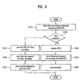
- FIG. 6 is a flowchart illustrating a method of recording a broadcasting program from the timer recording method of Figure 5;
- FIG. 7 is a flowchart illustrating a method of selecting a display recording device for the timer recording method of Figure 5;
- FIG. 8 is a flowchart illustrating a method of recording using a timer recording function according to the second embodiment of the present invention.
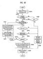
- FIG. 9 is a flowchart illustrating a method of recording using a timer recording function in a VCR in connection with the method of Figure 8.
- FIG. 10 is a flowchart illustrating a method of recording using a timer recording function in a DVD recorder in connection with the method of Figure 8.
- a display device 10 comprises a tuner 11, a controller 12, a wireless transmitter/receiver 13, a video decoder 14, an On Screen Display (OSD) processor 15, a video processor 16, a display 17, an interface 18, and a memory 19 which further includes a first memory 19a and a second memory 19b.
- OSD On Screen Display
- a user selects a desired channel via the tuner 11.
- the wireless transmitter/receiver 13 receives control related wireless data from an outside source or transmits control codes related to wireless data to a device such as a display recording device.
- the wireless communication can take place using an Infrared Data Association (IrDA) or Bluetooth, for example.
- IrDA Infrared Data Association
- Bluetooth for example.
- the video display 14 can decode the video information, transmitted from the transmission protocol (TP) via the selected channel, into red, green, and blue (RGB) signals.
- the OSD processor 15 processes the service information such as an Electronic Program Guide (EPG) information so that the EPG menu can be displayed on the display 17.
- EPG Electronic Program Guide
- the video processor 16 processes the RGB signals and the EPG information so as to display the EPG menu on the display 17, which can display the RGB video signals and/or the EPG menu screen.
- the interface 18 can be connected to at least one video display recorder, such as a first video display recording device 50 and a second video recording device 60.
- the interface 18 receives the received broadcast program or recorded program in the memory 53 via communication cables 30, 40 which connect to display recording device from the interface 18 of the display device 10.
- a first cable 30 connects the first display recording 50 and a second cable 40 connects the second display recording device 60.
- the memory 19 further includes the first memory 19a and the second memory 19b.
- the first memory 19a can store codes related to power on/off, start recording, and end recording, for example, according to the names of the manufacturers of the display recording devices.
- the second memory 19b can store the timer programmed recording status (e.g., broadcast program time for programmed recording, programmed channel for programmed recording) of programs selected and a detailed programmed recording information of the display recording devices 50, 60.
- the timer recording or timer programmed recording is programming a recording device to begin and end recording a broadcast program (e.g., movie, news, sports) on a certain channel at some time in the future.
- the operation of timer recording is illustrated in Figures 5 and 6 using flowcharts.
- control 12 transmits the time programmed recording status information stored in the second memory 19b and the control codes stored in the first memory 19a to the display recording devices 50, 60 via the wireless transmitter/receiver 13.
- the user enters data for timer recording (e.g., date and time for timer recording, channel to be recorded) using a wireless signal transmitter 20 (e.g., remote control device) to the wireless transmitter/receiver 13 while viewing the broadcast program on the display 17 or by using the EPG menu screen.
- a wireless signal transmitter 20 e.g., remote control device
- the user can also select the display recording device 50, 60.
- the control 12 stores information on the data for timer recording and the selected display recording device 50, 60 to the second memory 19a.
- a method of inputting command for timer recording is not limited to using the wireless signal transmitter, but can also be inputted directly using local keys (not illustrated) provided on the display device 10.
- the control 12 transmits in sequence the control codes (e.g., code for turning on power to the display recording device, code for starting recording), based on the manufacturer type, from the first memory 19a to the wireless receiver 51 of the display recording devices 50, 60 via the wireless transmitter/receiver 13. Moreover, when it is time to terminate the recording according to the selected timer recording, the control 12 transmits in sequence the control codes (e.g., code for stop recording, code for turning off power to the display recording device), based on the manufacturer type, from the second memory 19b to the wireless receiver 51 of the display recording devices 50, 60 via the wireless transmitter/receiver 13.
- the control 12 reads and acquires the control codes per manufacturer before sequentially transmitting to the display recording devices 50, 60. Therefore, it is convenient for the transmission to be made based on an order of preference (e.g., number of sales per country).
- the transmission cables 30, 40 connecting the display device 10 and the display recording devices 50, 60 can be a non-digital cable or a digital cable, such as IEEE1394 cable or high definition multimedia interface (HDMI) cable, depending on the selected display recording device.
- a non-digital cable or a digital cable such as IEEE1394 cable or high definition multimedia interface (HDMI) cable
- HDMI high definition multimedia interface
- the IEEE1394 cable and the HDMI cable are two-way communication cables whereas the non-digital cables are one-way communication cable.
- the display device can acquire the company code of the display recording device via the two-way communication line. Therefore, when the display device transmits the control code to the display recording device, the control code corresponds to the manufacturer of the display recording device.
- any combination of a VCR, a DVD recorder, a DVD recorder with HDD, a digital video home system (DVHS), can be used, for example.
- the recorded program(s) is transmitted to the display device 10 and in turn, the user can view the recorded program through the display 17 of the display device 10.
- the display recording device 50 includes a wireless receiver 51, an interface 52, a memory 53, and a control 54.
- an exemplary mode of operation of the display recording device is as follows.
- the wireless receiver 51 receives in sequence control codes (e.g., power on code, start recording code, end recording code, and power off code) from the wireless transmitter/receiver 13 of the display device 10. Thereafter, the wireless receiver 51 transmits the received control codes to the control 54.
- the control 54 turns on the display recording device 50, records the broadcasting program to the memory 53 (e.g., video cassette, DVD, HDD), and then terminates recording and turns power off.
- the memory 53 e.g., video cassette, DVD, HDD
- the composition of the display device according to the second embodiment, shown in Figure 4, is similar to the display device 10 of the first embodiment.
- the display device 10 of the second embodiment includes a tuner 11, a control 12, a wireless receiver 13a, a video decoder 14, an OSD processor 15, a video processor 16, a display 17, an interface 18, and a memory 19.
- the cables 70, 80 of the second embodiment are two-way communication cables or digital interface cables (e.g., IEEE 1394 cable, HDMI cable).
- the cable 70 connects the interface 18 of the display device 10 with the interface 52 of the display recording device 50.
- the wireless transmitter/receiver 13 of the first embodiment is replaced with the wireless receiver 13a in the second embodiment.
- the second embodiment includes only one memory, namely, a memory 19.
- the control codes e.g., power on/off, start/end recording
- timer recording status information e.g., program record start/end times, program record channel
- the two-way communication cables 70, 80 permit transmitting and receiving of data/information between the display device 10 and the display recording devices 70, 80, the display does not have to transmit control codes wirelessly, and since the display device 10 already has company code information of the display recording devices via the two-way communication cables, unnecessary transmissions of control signals according to preference can be reduced or eliminated.
- the second embodiment is operative if all the communication cables are two-way cables or digital interface cables. If, however, one of the cables is a one-way cable, such as the VCR cable or DVD cable, having a wireless transmitter/receiver 13 of the first embodiment would be more effective and efficient than the wireless receiver 13a of the second embodiment.
- the user enters the broadcast time and broadcast channel for timer recording to the display device, and the user inputted information is stored in the display device (S100).
- the display device determines whether more than two display recording devices are connected to the display device (S200). If it is determined that there are more than two display recording devices connected to the display device, the user can choose a first display recording device for timer recording a broadcast program and choose a second display recording device for timer recording another broadcast program (S300).
- display recording devices a VCR, a DVD recorder, a DVD recorder with HDD, and DVHS, to name a few, can be used.
- the control of the display device determines whether the current time matches the timer recording time (S400). If the program time and current time match, the control of the display device transmits the power on code and start recording code in sequence to the display recording devices (S500).
- the transmission of control codes can be made to the display recording devices based on preference (e.g., number of display recording devices sold per country). For example, assume that a first display recording device is manufactured by company A and a second display recording device is manufactured by company B. If the first display recording device has a higher sales volume than the second display recording device, the control codes are first transmitted to the first display recording device of company A, and thereafter transmitted to the second display recording device of company B.
- the selected display recording device turns on the power and records the broadcast program. After that, the control signal of the display device determines whether it is time to end recording of the broadcasting program (S600). If the control of the display device determines that is time to end recording, the control transmits the end recording code and the power off code in sequence to the display recording devices based on the preference (S700).
- a user selects a timer recording function or a program guide menu (or key) using a wireless signal transmitter 20 (S 110).
- the display device determines whether an electronic program guide (EPG) is available (S120). If the EPG is not available, an OSD is provided for timer recording (S 130). Thereafter, the user can enter timer recording information and the channel to be recorded (S 140). Upon completion of command input, the entered information is stored and the OSD is cleared from the screen (S 150).
- EPG electronic program guide
- the EPG menu is displayed (S160). From the EPG menu, the user can select timer recording (S 170), and the selected information is then stored (S 180).
- FIG. 7 illustrating a method of selecting a display recording device for the timer recording method in connection with Figure 5, at least two display recording devices are connected to the display device.
- the user can select from the OSD a timer recording option based on the type of connection cable or the display recording device (S310).
- the user can choose between a non-digital cable or a digital interface cable (S320).
- the non-digital cable enables one-way communication between the display device and the display recording device.
- the digital cable enables two-way communication between the display device and the display recording device.
- one display recording device can be a VCR connected with a non-digital cable
- the other display recording device can be a DVD recorder connected with a digital interface cable (e.g., IEEE1394 cable or HDMI cable).
- a message on the OSD would appear to ask the user to select a connection cable connected to either the display device or the display recording device from the two non-digital cables.
- the user can choose any one of the connected display recording devices (e.g., VCR or DVD recorder) from the menu on the OSD (S330).
- the connected display recording devices e.g., VCR or DVD recorder
- the display device determines the status of the connection between the display device and the user selected display recording device (S340). If it is determined that the cable is not connected or improperly connected, a message is provided asking the user to check the connection and to establish proper connection (S350). If, however, it is determined that the connection of the cable is properly established, the display device then checks if it is time to begin recording the user-selected broadcast program (S400).
- the EPG can be selected by the user by pressing the EPG selection button (or key) or the EPG from the menu (S1100).
- the EPG screen is display on the screen from which the user can select timer recording function, including the channel to be recorded, or the user can choose to view a certain broadcast program at a specified future time (S 1200). Thereafter, the display device determines which selection (i.e., timer recording or timer viewing) was made by the user (S 1300).
- a timer viewing confirmation inquiry i.e., yes or no
- the display device stores the timer viewing information (e.g., time and channel) (S1500).
- timer viewing the certain broadcast program is displayed over the currently viewing broadcast program at the time of the programmed time. For example, if the viewer was viewing a broadcast program on Channel 7 and the timer viewing programmed broadcast program is on Channel 10, when it is time to view according to the programmed timer viewing feature, the channel switches from Channel 7 to Channel 10.
- a message indicating impending channel change can be displayed at specified time prior to switching the channel.
- the message indicating change of channel from Channel 7 to Channel 10 can be displayed two minutes before the switch.
- the message display can be in various forms, such as a picture-in-picture, a picture-on-picture, a ticker, etc.
- the display device can be automatically turned on if the display device is turned off, and it is time programmed in the timer viewing feature, the display device can be automatically turned on.
- the user is asked to select a display recording device (e.g., VCR or DVD recorder) from the OSD menu (S1600).
- a display recording device e.g., VCR or DVD recorder
- the connection status between the display device and the VCR is confirmed (S 1700), and the control codes for the VCR based on manufacturer preference can be sorted (S1900).
- the DVD recorder is selected to perform timer recording, the connection status between the display device and the DVD recorder is checked (S 1800).
- the display device stores the timer recording information of the selected broadcasting program (e.g., display recording device, channel to be recorded, and detailed information including time) (S2000).
- the control of the display device determines whether it is time to begin recording (S2100). If it is time to begin recording, the display device transmits in sequence the control code for turning on power of the display recording device and the control code for begin recording according to the preference of the display recording device manufacturer (S2200). Thereafter, the control of the display device determines if it is time to stop recording (S2300). If it is time to stop recording, the display device transmits in sequence the control code for end recording and the control code for turning off power of the display recording device according to the preference of the display recording device manufacturer (S2400).
- the display device determines whether the broadcast program is a paid program (S2030). If it is determined that the broadcast program is not a paid program, the timer recording information of the selected broadcast program is stored in the display device (S2040), and as message notifying that the timer recording has been programmed is displayed (S2090).
- a message is displayed asking if the user wants to add an item (S2050).
- Adding an item includes a display on screen asking the user to select any one of the choices (S2051).
- the choices are video, audio, or confirm.
- the user is further asked to select primary audio, secondary audio, or primary/secondary audio (S2052). Thereafter, the selection is stored (S2056).
- the secondary audio can include a plurality of languages, such as English, Chinese, Japanese, and French.
- multi-view refers to a plurality of camera angles from which the video was shot (e.g., video shot from camera 1, camera 2, or camera 3). If the user selects the multi-view function, the user can then select the camera angle (or which camera) to view the video (S2054), and this selection information is temporarily stored (S2056).
- the user selects a primary video or secondary video to view the video (S2055), and this selection is stored (S2056).
- a digital broadcasting standard definition quality
- the secondary video which means three to four broadcast programs transmitted simultaneously, the user would have to choose from one broadcast program from the transmission.
- the user is asked if the user desires to add another item (S2060). If the user selects to add another item, the user can then add a new item such as a multi-view function, primary audio or video, or secondary audio or video (refer to S2050 for detail). However, if the user chooses not to add another item, the user is asked to pay for the paid program (e.g., pay-per-view) (S2070).
- a paid program e.g., pay-per-view
- the recording information temporarily stored is stored in the display device (S2080).
- the temporality stored recording information would be timer recording information and the channel to be recorded information.
- the EPG screen is presented to the user for making other selections (S1200).
- the user is asked to add an item (S2050) as is the case in Figure 9. If however, the user decides to change the display recording device, the other display recording device currently connected to the display device (e.g., computer) besides the selected display recording device is determined and displayed (S2081). Thereafter, the user can select one of the displayed display recording device (S2091), and after which, the user can be asked to add an item (S2050). The remaining steps are same as the steps of Figure 9.
Landscapes
- Engineering & Computer Science (AREA)
- Multimedia (AREA)
- Signal Processing (AREA)
- Business, Economics & Management (AREA)
- Finance (AREA)
- Strategic Management (AREA)
- Databases & Information Systems (AREA)
- Human Computer Interaction (AREA)
- Two-Way Televisions, Distribution Of Moving Picture Or The Like (AREA)
- Television Signal Processing For Recording (AREA)
- Details Of Television Systems (AREA)
Abstract
Description
- The present invention relates to a method of recording. It more particularly relates to a method of timer recording a broadcast program.
- Since the introduction of color television, digital technology, such as stereo sound, a remote control device, and closed captioning function, to name a few, has appeared as a part of the television system. Starting in the '90s, technology related to computers and network has been rapidly increasing and such a rapid improvement has fueled the public's interest for higher quality picture and multi-function television - hence, the introduction of digital television (DTV).
- Broadcasting of digital data is advantageous since all elements or factors such as video, audio, and data are converted into digital data and compressed, as is done with computer data. Furthermore, if video and audio is digital signal processed, the data can be converted into digital data, which permits transmission of digital data with other data attached thereto.
- Based on current technology, it is possible to transmit one high definition television program and three standard definition television program via a single channel. By broadcasting using digital signals, the quality of the picture can be improved significantly. Moreover, digital signal broadcasting self-resolves problems such as ghosting, which is caused by signals bouncing off obstacles, while providing quality and sound to home systems before enjoyed only in movie theaters.
- An example of a digital television, whose advantageous are described above, includes an input device such as a remote control device, an audio and video (A/V) processor for decoding audio and video signals, a data processor for separating various channel information from service information, a database for storing the separated channel information, and a controller for controlling the display of a menu and an Electronic Program Guide (EPG).
- The operation of the digital television is as follows. The digital television receives broadcast signals. Next, a demultiplexer demultiplexes the audio and video information and the service information from the received broadcast signals. The separated audio and video signals are processed to the A/V processor, and the service information is stored in the database. Here, the service information includes Program Association Table (PAT), Time Date Table (TDT)/Time Offset Table (TOT), and Event Information Table (EIT) to name a few. More specifically, the PAT includes information related to a plurality of programs, the TDT/TOT includes time information of each program, and the EIT includes information such as title, synopsis, program rating, and start/end time of the program.
- The data processor extracts the EIT information from the stored service information, and then formats the extracted information using a specified format before storing the formatted information in the database. To describe the EPG, the following figures are used.
- Figure 1 is an example of a conventional EPG menu screen, and Figure 2 illustrates the EPG menu screen of Figure 1 when a specific channel is selected.
- In Figure 1, the EPG menu screen illustrates channels, order of programs, and time corresponding to the programs. In Figure 2, a viewer selects a specific channel from the EPG of Figure 1. If the viewer selects MBC TV, for example, the EPG provides a detailed information of the current program and the following program broadcasting on MBC.
- As illustrated in Figures 1 and 2, the stored service information provided via the EPG menu screen, including the current program and the following program broadcasting on the selected channel, according to the viewer's selection. Furthermore, the EPG provides a list of plurality of channels, current time information, title of the program (A), time of broadcast (B), and a synopsis of the program (C).
- After reviewing the provided information, the viewer can choose to record the current program or time record another program. If the program is selected to be time recorded, the controller records the time recorded program to a hard disk drive (HDD) provided internally at the scheduled time. However, if the television does not have an integrated HDD, the program can be recorded to an external device such as a video cassette recorder (VCR) or a digital video disk (DVD) recorder.
- Although the conventional technology, as describe above, is functional, there are some problems that can be improved. First, the television does not have a time-record function. Second, even with the EPG, the display device cannot record if a memory device is not internally provided. Lastly, it is difficult for the viewer to time-record the VCR or the DVD recorder compared to programming the EPG of the display device to record a future program.
- The present invention seeks to provide an improved display device and method for timer recording of broadcast programs.
- Advantages and features of embodiments of the invention will be set forth in part in the description which follows and which will become apparent to those having ordinary skill in the art upon examination of the following.
- A first aspect of the invention provides a method of recording using a timer recording function in a display device, the method comprising: receiving an input data, wherein the input data is a user inputted instruction information for executing a timer recording function; storing the instruction information which includes an instruction for a display recording device to begin and end recording a broadcast program of a certain designated channel at a specified time period in the future; determining whether at least two display recording devices are connected to the display device; selecting the display recording device for recording the broadcast program; and transmitting control data to the selected display recording device.
- Another aspect of the invention provides a method of recording using a timer recording function in a display device, the method comprising: displaying an Electronic Program Guide (EPG); selecting from the EPG a broadcast program for timer recording or for timer viewing; storing information on timer viewing if timer viewing is selected, wherein the timer viewing information includes a specified time in the future to begin viewing the selected broadcast program on a certain designated channel; and returning to the EPG display after the timer viewing information is stored.
- Another aspect of the invention provides a method of recording using a timer recording function in a display device, the method comprising: displaying an Electronic Program Guide (EPG); selecting from the EPG a broadcast program for timer recording or for timer viewing; storing information on timer viewing if timer viewing is selected, wherein the timer viewing information includes a specified time in the future to begin viewing the selected broadcast program on a certain designated channel; and returning to the EPG display after the timer viewing information is stored.
- Another aspect of the invention provides a display device, comprising: a wireless transceiver arranged to receive input data from an outside source and transmitting control data for controlling at least one display recording device; at least one memory arranged to store the input data and the control data, wherein the first memory is arranged to store the input data and the second memory is arranged to store the control data; and a control unit arranged to acquire the control data from the second memory and transmit the control data to the display recording device via the wireless transceiver.
- Another aspect of the invention provides a display device, comprising: a wireless receiver arranged to receive input data from an outside source; a memory arranged to store the input data and the control data; a control unit arranged to acquire the control data from the memory; and a two-way communication cable connecting the display device and the display recording device.
- It is to be understood that both the foregoing general description and the following detailed description of the present invention are exemplary and explanatory and are intended to provide further explanation of the invention as claimed.
- Embodiments of the invention will now be described by way of non-limiting example only, with reference to the drawings, in which:
- FIG. 1 illustrates an example of a conventional EPG menu screen;
- FIG. 2 illustrates the EPG menu screen of Figure 1 when a specific channel is selected;
- FIG. 3 illustrates a block diagram of a display device according to a first embodiment of the present invention;
- FIG. 4 is another block diagram of display device illustrating a second embodiment of the present invention;
- FIG. 5 is a flowchart illustrating a method of timer recording in a display device according to the present invention;
- FIG. 6 is a flowchart illustrating a method of recording a broadcasting program from the timer recording method of Figure 5;
- FIG. 7 is a flowchart illustrating a method of selecting a display recording device for the timer recording method of Figure 5;
- FIG. 8 is a flowchart illustrating a method of recording using a timer recording function according to the second embodiment of the present invention;
- FIG. 9 is a flowchart illustrating a method of recording using a timer recording function in a VCR in connection with the method of Figure 8; and
- FIG. 10 is a flowchart illustrating a method of recording using a timer recording function in a DVD recorder in connection with the method of Figure 8.
- Wherever possible, the same reference numbers will be used throughout the drawings to refer to the same or like parts.
- In Figure 3, a
display device 10 comprises atuner 11, acontroller 12, a wireless transmitter/receiver 13, avideo decoder 14, an On Screen Display (OSD)processor 15, avideo processor 16, adisplay 17, aninterface 18, and a memory 19 which further includes afirst memory 19a and asecond memory 19b. - In operation, a user selects a desired channel via the
tuner 11. The wireless transmitter/receiver 13 receives control related wireless data from an outside source or transmits control codes related to wireless data to a device such as a display recording device. Here, the wireless communication can take place using an Infrared Data Association (IrDA) or Bluetooth, for example. - In addition, the
video display 14 can decode the video information, transmitted from the transmission protocol (TP) via the selected channel, into red, green, and blue (RGB) signals. The OSDprocessor 15 processes the service information such as an Electronic Program Guide (EPG) information so that the EPG menu can be displayed on thedisplay 17. - The
video processor 16 processes the RGB signals and the EPG information so as to display the EPG menu on thedisplay 17, which can display the RGB video signals and/or the EPG menu screen. - Furthermore, the
interface 18 can be connected to at least one video display recorder, such as a first videodisplay recording device 50 and a secondvideo recording device 60. Theinterface 18 receives the received broadcast program or recorded program in thememory 53 viacommunication cables interface 18 of thedisplay device 10. In this figure, afirst cable 30 connects thefirst display recording 50 and asecond cable 40 connects the seconddisplay recording device 60. - The memory 19 further includes the
first memory 19a and thesecond memory 19b. Thefirst memory 19a can store codes related to power on/off, start recording, and end recording, for example, according to the names of the manufacturers of the display recording devices. In addition, thesecond memory 19b can store the timer programmed recording status (e.g., broadcast program time for programmed recording, programmed channel for programmed recording) of programs selected and a detailed programmed recording information of thedisplay recording devices - In addition to controlling the
display device 10, thecontrol 12 transmits the time programmed recording status information stored in thesecond memory 19b and the control codes stored in thefirst memory 19a to thedisplay recording devices receiver 13. - In the first embodiment, the user enters data for timer recording (e.g., date and time for timer recording, channel to be recorded) using a wireless signal transmitter 20 (e.g., remote control device) to the wireless transmitter/
receiver 13 while viewing the broadcast program on thedisplay 17 or by using the EPG menu screen. In timer recording, the user can also select thedisplay recording device control 12 stores information on the data for timer recording and the selecteddisplay recording device second memory 19a. In this embodiment, a method of inputting command for timer recording is not limited to using the wireless signal transmitter, but can also be inputted directly using local keys (not illustrated) provided on thedisplay device 10. - When it is time to start recording according to the selected timer recording, the
control 12 transmits in sequence the control codes (e.g., code for turning on power to the display recording device, code for starting recording), based on the manufacturer type, from thefirst memory 19a to thewireless receiver 51 of thedisplay recording devices receiver 13. Moreover, when it is time to terminate the recording according to the selected timer recording, thecontrol 12 transmits in sequence the control codes (e.g., code for stop recording, code for turning off power to the display recording device), based on the manufacturer type, from thesecond memory 19b to thewireless receiver 51 of thedisplay recording devices receiver 13. Here, thecontrol 12 reads and acquires the control codes per manufacturer before sequentially transmitting to thedisplay recording devices - Furthermore, the
transmission cables display device 10 and thedisplay recording devices display recording devices - It is through the
communication cables display device 10 and in turn, the user can view the recorded program through thedisplay 17 of thedisplay device 10. - The
display recording device 50 includes awireless receiver 51, aninterface 52, amemory 53, and acontrol 54. In this embodiment an exemplary mode of operation of the display recording device is as follows. Thewireless receiver 51 receives in sequence control codes (e.g., power on code, start recording code, end recording code, and power off code) from the wireless transmitter/receiver 13 of thedisplay device 10. Thereafter, thewireless receiver 51 transmits the received control codes to thecontrol 54. According to the action commands of the control codes, thecontrol 54 turns on thedisplay recording device 50, records the broadcasting program to the memory 53 (e.g., video cassette, DVD, HDD), and then terminates recording and turns power off. - The composition of the display device according to the second embodiment, shown in Figure 4, is similar to the
display device 10 of the first embodiment. In detail, thedisplay device 10 of the second embodiment includes atuner 11, acontrol 12, a wireless receiver 13a, avideo decoder 14, anOSD processor 15, avideo processor 16, adisplay 17, aninterface 18, and a memory 19. - Unlike the first embodiment, the cables 70, 80 of the second embodiment are two-way communication cables or digital interface cables (e.g., IEEE 1394 cable, HDMI cable). Here, the cable 70 connects the
interface 18 of thedisplay device 10 with theinterface 52 of thedisplay recording device 50. In addition, the wireless transmitter/receiver 13 of the first embodiment is replaced with the wireless receiver 13a in the second embodiment. Furthermore, where the first embodiment included afirst memory 19a and asecond memory 19b, the second embodiment includes only one memory, namely, a memory 19. As such, the control codes (e.g., power on/off, start/end recording) and timer recording status information (e.g., program record start/end times, program record channel), formerly stored in two memories are stored in the memory 19. - To put differently, because the two-way communication cables 70, 80 permit transmitting and receiving of data/information between the
display device 10 and the display recording devices 70, 80, the display does not have to transmit control codes wirelessly, and since thedisplay device 10 already has company code information of the display recording devices via the two-way communication cables, unnecessary transmissions of control signals according to preference can be reduced or eliminated. - The second embodiment is operative if all the communication cables are two-way cables or digital interface cables. If, however, one of the cables is a one-way cable, such as the VCR cable or DVD cable, having a wireless transmitter/
receiver 13 of the first embodiment would be more effective and efficient than the wireless receiver 13a of the second embodiment. - As shown in Figure 5, the user enters the broadcast time and broadcast channel for timer recording to the display device, and the user inputted information is stored in the display device (S100). Next, the display device determines whether more than two display recording devices are connected to the display device (S200). If it is determined that there are more than two display recording devices connected to the display device, the user can choose a first display recording device for timer recording a broadcast program and choose a second display recording device for timer recording another broadcast program (S300). As examples of display recording devices, a VCR, a DVD recorder, a DVD recorder with HDD, and DVHS, to name a few, can be used.
- After the user has selected the display recording device and the selection is stored in the display device, the control of the display device determines whether the current time matches the timer recording time (S400). If the program time and current time match, the control of the display device transmits the power on code and start recording code in sequence to the display recording devices (S500). Here, the transmission of control codes can be made to the display recording devices based on preference (e.g., number of display recording devices sold per country). For example, assume that a first display recording device is manufactured by company A and a second display recording device is manufactured by company B. If the first display recording device has a higher sales volume than the second display recording device, the control codes are first transmitted to the first display recording device of company A, and thereafter transmitted to the second display recording device of company B.
- Based on the transmitted control codes, the selected display recording device turns on the power and records the broadcast program. After that, the control signal of the display device determines whether it is time to end recording of the broadcasting program (S600). If the control of the display device determines that is time to end recording, the control transmits the end recording code and the power off code in sequence to the display recording devices based on the preference (S700).
- Turning now to the flowchart of Figure 6, illustrating a method of recording a broadcasting program from the timer recording method of Figure 5, a user selects a timer recording function or a program guide menu (or key) using a wireless signal transmitter 20 (S 110). The display device then determines whether an electronic program guide (EPG) is available (S120). If the EPG is not available, an OSD is provided for timer recording (S 130). Thereafter, the user can enter timer recording information and the channel to be recorded (S 140). Upon completion of command input, the entered information is stored and the OSD is cleared from the screen (S 150).
- If, however, the EPG is available, the EPG menu is displayed (S160). From the EPG menu, the user can select timer recording (S 170), and the selected information is then stored (S 180).
- Turning now to the flowchart of Figure 7 illustrating a method of selecting a display recording device for the timer recording method in connection with Figure 5, at least two display recording devices are connected to the display device. The user can select from the OSD a timer recording option based on the type of connection cable or the display recording device (S310).
- If the user selects to record using a timer recording function based on the connection cable type, the user can choose between a non-digital cable or a digital interface cable (S320). The non-digital cable enables one-way communication between the display device and the display recording device. The digital cable enables two-way communication between the display device and the display recording device. For example, if the user selects the choose a recording medium based on the connection cable, one display recording device can be a VCR connected with a non-digital cable, while the other display recording device can be a DVD recorder connected with a digital interface cable (e.g., IEEE1394 cable or HDMI cable). However, if the connection cables for the VCR and the DVD recorder are both non-digital cables, a message on the OSD would appear to ask the user to select a connection cable connected to either the display device or the display recording device from the two non-digital cables.
- If, on the other hand, the user selects to record using a timer recording function based on the recording device type, the user can choose any one of the connected display recording devices (e.g., VCR or DVD recorder) from the menu on the OSD (S330).
- After the user has made a selection between the connection cable-based recording or the display recording device-based recording, the display device determines the status of the connection between the display device and the user selected display recording device (S340). If it is determined that the cable is not connected or improperly connected, a message is provided asking the user to check the connection and to establish proper connection (S350). If, however, it is determined that the connection of the cable is properly established, the display device then checks if it is time to begin recording the user-selected broadcast program (S400).
- In Figure 8, the EPG can be selected by the user by pressing the EPG selection button (or key) or the EPG from the menu (S1100). When selected, the EPG screen is display on the screen from which the user can select timer recording function, including the channel to be recorded, or the user can choose to view a certain broadcast program at a specified future time (S 1200). Thereafter, the display device determines which selection (i.e., timer recording or timer viewing) was made by the user (S 1300).
- If it is determined that the user has selected to view a certain broadcast program at a specified future time, a timer viewing confirmation inquiry (i.e., yes or no) is displayed on the screen (S1400). In response, if the user selects 'yes,' the display device stores the timer viewing information (e.g., time and channel) (S1500). In operation of timer viewing, the certain broadcast program is displayed over the currently viewing broadcast program at the time of the programmed time. For example, if the viewer was viewing a broadcast program on Channel 7 and the timer viewing programmed broadcast program is on
Channel 10, when it is time to view according to the programmed timer viewing feature, the channel switches from Channel 7 toChannel 10. Moreover, a message indicating impending channel change can be displayed at specified time prior to switching the channel. For example, the message indicating change of channel from Channel 7 to Channel 10 can be displayed two minutes before the switch. Also, the message display can be in various forms, such as a picture-in-picture, a picture-on-picture, a ticker, etc. In addition, if the display device is turned off, and it is time programmed in the timer viewing feature, the display device can be automatically turned on. - However, if it is determined that the user has selected to record a broadcast program, the user is asked to select a display recording device (e.g., VCR or DVD recorder) from the OSD menu (S1600).
- Here, if the VCR is selected as a medium to perform timer recording, the connection status between the display device and the VCR is confirmed (S 1700), and the control codes for the VCR based on manufacturer preference can be sorted (S1900). However, if the DVD recorder is selected to perform timer recording, the connection status between the display device and the DVD recorder is checked (S 1800).
- After the connection status has been determined, the display device stores the timer recording information of the selected broadcasting program (e.g., display recording device, channel to be recorded, and detailed information including time) (S2000). Next, the control of the display device determines whether it is time to begin recording (S2100). If it is time to begin recording, the display device transmits in sequence the control code for turning on power of the display recording device and the control code for begin recording according to the preference of the display recording device manufacturer (S2200). Thereafter, the control of the display device determines if it is time to stop recording (S2300). If it is time to stop recording, the display device transmits in sequence the control code for end recording and the control code for turning off power of the display recording device according to the preference of the display recording device manufacturer (S2400).
- In Figure 9, after the connection has been firmly established between the display device and the VCR (or a video tape recorder), the control codes are sorted and the VCR recording screen is displayed as OSD (S2010). Next, the display device asks via the OSD whether the user wishes to select additional recording features (S2020).
- If the user does not decide to perform a detailed recording, the display device determines whether the broadcast program is a paid program (S2030). If it is determined that the broadcast program is not a paid program, the timer recording information of the selected broadcast program is stored in the display device (S2040), and as message notifying that the timer recording has been programmed is displayed (S2090).
- However, if it is determined that the user has decided to perform a detailed recording, or the broadcast program is a paid program, a message is displayed asking if the user wants to add an item (S2050). Adding an item includes a display on screen asking the user to select any one of the choices (S2051). The choices are video, audio, or confirm.
- If the user selects 'confirm,' it means that a paid program has been purchased, or the user no longer desires to continue with the detailed recording. Therefore, the confirmation of end detailed recording is displayed (S2090).
- Alternatively, if it is determined that the user has selected 'audio,' the user is further asked to select primary audio, secondary audio, or primary/secondary audio (S2052). Thereafter, the selection is stored (S2056). Here, the secondary audio can include a plurality of languages, such as English, Chinese, Japanese, and French.
- Alternatively, if it is determined that the user has selected 'video,' the user is asked is select a multi-view function (S2053). Here, multi-view refers to a plurality of camera angles from which the video was shot (e.g., video shot from
camera 1,camera 2, or camera 3). If the user selects the multi-view function, the user can then select the camera angle (or which camera) to view the video (S2054), and this selection information is temporarily stored (S2056). - However, if the user did not select the multi-view function, the user then selects a primary video or secondary video to view the video (S2055), and this selection is stored (S2056). Here, if a digital broadcasting (standard definition quality) is used in the secondary video which means three to four broadcast programs transmitted simultaneously, the user would have to choose from one broadcast program from the transmission.
- Next, the user is asked if the user desires to add another item (S2060). If the user selects to add another item, the user can then add a new item such as a multi-view function, primary audio or video, or secondary audio or video (refer to S2050 for detail). However, if the user chooses not to add another item, the user is asked to pay for the paid program (e.g., pay-per-view) (S2070).
- If the user pays for the paid program, the recording information temporarily stored is stored in the display device (S2080). Here, the temporality stored recording information would be timer recording information and the channel to be recorded information. However, if the user decides not to pay for paid program, the EPG screen is presented to the user for making other selections (S1200).
- In Figure 10, the steps of timer recording are similar to that of Figure 9 with an exception of a step providing a user an option to change the display recording device (S2071).
- If the display recording device is kept and not changed by the user, the user is asked to add an item (S2050) as is the case in Figure 9. If however, the user decides to change the display recording device, the other display recording device currently connected to the display device (e.g., computer) besides the selected display recording device is determined and displayed (S2081). Thereafter, the user can select one of the displayed display recording device (S2091), and after which, the user can be asked to add an item (S2050). The remaining steps are same as the steps of Figure 9.
- It will be apparent to those skilled in the art that various modifications and variations can be made in the present invention without departing from the scope of the invention. Thus, it is intended that the present invention covers the modifications and variations of this invention provided they come within the scope of the appended claims.
Claims (29)
- A method of recording using a timer recording function in a display device, the method comprising:receiving an input data, wherein the input data is a user inputted instruction information for executing a timer recording function;storing the instruction information which includes an instruction for a display recording device to begin and end recording a broadcast program of a certain designated channel at a specified time period in the future;determining whether at least two display recording devices are connected to the display device;selecting the display recording device for recording the broadcast program; andtransmitting control data to the selected display recording device.
- The method of claim 1, wherein the control data includes a first code which instructs the display recording device to turn on power, a second code which instructs the display recording device to begin recording, a third code which instructs the display recording device to stop recording, and a fourth code which instructs the display recording device to turn off power.
- The method of claim 1 or 2, further comprising:determining if an Electronic Program Guide (EPG) is available;displaying the EPG for providing broadcast information if the EGP is available, wherein the broadcast information includes begin and end time of a broadcast program and a channel on which the broadcast program is broadcasted;selecting the broadcast information to execute timer recording function; andstoring the selected broadcast information.
- The method of claim 1 or 2, further comprising:determining if an Electronic Program Guide (EPG) is available;providing an On Screen Display (OSD) for allowing the user to enter the instruction information if the EPG is not available; andstoring the entered instruction information.
- The method of any preceding claim, wherein the display recording device is selected based on a first cable or a second cable.
- The method of claim 5, wherein the second cable is a digital cable which enables two-way communication between the display device and the display recording device.
- The method of any preceding claim, wherein the display recording device is selected based on a specific display recording device.
- The method of claim 7, wherein the display recording device is a VCR, VTR, DVD recorder, DVD recorder with HDD, or DVHS
- A method of recording using a timer recording function in a display device, the method comprising:displaying an Electronic Program Guide (EPG);selecting from the EPG a broadcast program for timer recording or for timer viewing;selecting a display recording device for recording the broadcast program if the timer recording is selected;organizing control data for providing operational instructions to the display recording device;storing information of the broadcast program and the control data; andtransmitting in sequence the control data to the display recording device.
- The method of claim 9, wherein the control data includes a first code which instructs the display recording device to turn on power, a second code which instructs the display recording device to begin recording, a third code which instructs the display recording device to stop recording, and a fourth code which instructs the display recording device to turn off power.
- The method of claim 10, wherein the first code and the second code are transmitted in sequence to the display recording device when a current time matches begin recording time entered by a user.
- The method of claim 10 or 11, wherein the third code and the fourth code are transmitted in sequence to the display recording device when a current time matches a ending time of the broadcast program.
- The method of claim 10 or 11, wherein the third code and the fourth code are transmitted in sequence to the display recording device when a current time matches stop recording time entered by a user.
- A method of recording using a timer recording function in a display device, the method comprising:displaying an Electronic Program Guide (EPG);selecting from the EPG a broadcast program for timer recording or for timer viewing;storing information on timer viewing if timer viewing is selected, wherein the timer viewing information includes a specified time in the future to begin viewing the selected broadcast program on a certain designated channel; andreturning to the EPG display after the timer viewing information is stored.
- The method of claim 14, further comprising:selecting a display recording device for recording the broadcast program if the timer recording is selected;organizing control codes for providing operational instructions to the display recording device;storing information of the broadcast program and the control codes; andtransmitting in sequence the control codes to the display recording device.
- The method of claim 14 or 15, further comprising:displaying a selection for a detailed recording feature;selecting the detailed recording feature which includes a video option and an audio option;selecting any one of the video option, the audio option, or the video and audio options;storing, temporarily, the selected option until purchase of the selected option is made;storing the selected option if the selected option is purchased; anddisplaying confirmation of the detailed recording feature selection.
- The method of claim 16, wherein the video option includes a multi-view feature, which includes camera shots from various angles, and a primary video or a secondary video.
- The method of claim 17, wherein the secondary video is any one of a plurality of the broadcasting programs received in standard definition (SD) quality.
- The method of claim 18, wherein the audio option includes a primary audio or a secondary audio.
- The method of claim 19, wherein the primary audio is a language in which a broadcast is being broadcasted, and the secondary audio is the language in which an original broadcast was recorded or filmed.
- The method of any one of claims 16 to 20, further comprising:displaying a display recording device change option before selecting any one of the video option, the audio option, or the video and audio options;selecting from the display recording device change option to change the display recording device;displaying the plurality of display recording devices connected to the display device; andselecting any one of the connected display recording device.
- A display device, comprising:a wireless transceiver arranged to receive input data from an outside source and transmitting control data for controlling at least one display recording device;at least one memory arranged to store the input data and the control data, wherein the first memory is arranged to store the input data and the second memory is arranged to store the control data; anda control unit arranged to acquire the control data from the second memory and to transmit the control data to the display recording device via the wireless transceiver.
- The device of claim 22, wherein the outside source is a remote control device.
- The device of claim 22, wherein the input data, which is stored in the first memory, is a user inputted command for executing timer recording and is arranged to be transmitted to the display recording device from the wireless transceiver.
- The device of claim 22, wherein the control data, which is stored in the second memory, includes a code for turning on power to the display recording device, and/or a code for begin recording from the display recording device, and/or a code for end recording from the display device and/or a code for turning off power to the display recording device.
- The device of claim 22, further comprising a communication cable arranged to transmit a recorded video from the display recording device to the display device.
- A display device, comprising:a wireless receiver arranged to receive input data from an outside source;a memory arranged to store the input data and the control data;a control unit arranged to acquire the control data from the memory; anda two-way communication cable connecting the display device and the display recording device.
- The device of claim 27, wherein the outside source is a remote control device and/or wherein the input data is a user inputted command for executing timer recording and is transmitted to the display recording device via the two-way communication cable and/or wherein the control data includes codes for turning on/off power to the display recording device and code for begin/end recording from the display recording device.
- The device of claim 27 or 28, wherein the two-way communication cable is a digital cable.
Applications Claiming Priority (1)
| Application Number | Priority Date | Filing Date | Title |
|---|---|---|---|
| KR1020050042523A KR100698272B1 (en) | 2005-05-20 | 2005-05-20 | Video equipment and scheduled recording method using the same |
Publications (2)
| Publication Number | Publication Date |
|---|---|
| EP1725026A2 true EP1725026A2 (en) | 2006-11-22 |
| EP1725026A3 EP1725026A3 (en) | 2008-10-29 |
Family
ID=36698628
Family Applications (1)
| Application Number | Title | Priority Date | Filing Date |
|---|---|---|---|
| EP06252638A Withdrawn EP1725026A3 (en) | 2005-05-20 | 2006-05-19 | Display device and method for timer recording a broadcast program |
Country Status (5)
| Country | Link |
|---|---|
| US (1) | US8503865B2 (en) |
| EP (1) | EP1725026A3 (en) |
| JP (1) | JP4464367B2 (en) |
| KR (1) | KR100698272B1 (en) |
| CN (1) | CN1867052A (en) |
Cited By (1)
| Publication number | Priority date | Publication date | Assignee | Title |
|---|---|---|---|---|
| EP2076029A1 (en) * | 2007-12-27 | 2009-07-01 | EchoStar Technologies Corporation | A method of informing a first electronic device of the control of a second electronic device, and an electronic system |
Families Citing this family (7)
| Publication number | Priority date | Publication date | Assignee | Title |
|---|---|---|---|---|
| JP4533395B2 (en) * | 2007-03-13 | 2010-09-01 | キヤノン株式会社 | Digital broadcast receiving apparatus and control method thereof |
| JP2009038577A (en) * | 2007-08-01 | 2009-02-19 | Sharp Corp | Digital broadcast receiver and recording reservation setting method |
| JP5339573B2 (en) | 2007-11-15 | 2013-11-13 | ソニー エスパナ,エス.エー. | Display device, program information display method in display device, receiving device, and signal transmission method in receiving device |
| KR101470630B1 (en) * | 2008-03-06 | 2014-12-09 | 엘지디스플레이 주식회사 | TV system |
| KR101552147B1 (en) * | 2008-04-24 | 2015-09-11 | 삼성전자주식회사 | Method for recommending broadcasting contents and apparatus thereof |
| KR101528857B1 (en) * | 2008-04-24 | 2015-06-16 | 삼성전자주식회사 | A method and apparatus for providing broadcast program information |
| KR101517769B1 (en) * | 2008-04-24 | 2015-05-06 | 삼성전자주식회사 | A method and apparatus for recommending broadcast contents in a media content playback apparatus |
Family Cites Families (21)
| Publication number | Priority date | Publication date | Assignee | Title |
|---|---|---|---|---|
| JP2981293B2 (en) | 1991-01-23 | 1999-11-22 | シャープ株式会社 | Television receiver |
| JPH0775030A (en) | 1993-07-07 | 1995-03-17 | Hitachi Ltd | Television receiver |
| JP3567438B2 (en) | 1993-12-28 | 2004-09-22 | ソニー株式会社 | Electronic device control method |
| KR100209677B1 (en) | 1996-02-27 | 1999-07-15 | 구자홍 | How to use TV to provide data for recording reservation to TV, TV and VRC adapted to this method |
| JP3911047B2 (en) | 1996-04-30 | 2007-05-09 | ソニー株式会社 | Recording reservation control system and recording reservation control method |
| US5986650A (en) * | 1996-07-03 | 1999-11-16 | News America Publications, Inc. | Electronic television program guide schedule system and method with scan feature |
| DE69735516T2 (en) | 1996-10-08 | 2006-10-26 | Matsushita Electric Industrial Co., Ltd., Kadoma | Information receiving method and apparatus using this |
| JP3453489B2 (en) | 1997-03-21 | 2003-10-06 | キヤノン株式会社 | Electronic device control device and image editing device |
| TW392402B (en) | 1997-10-22 | 2000-06-01 | Hitachi Ltd | Method for using audio and video machine and audio and video machine system |
| JPH11232727A (en) | 1998-02-18 | 1999-08-27 | Hitachi Ltd | AV equipment and recording methods for AV equipment |
| JPH11259926A (en) | 1998-03-16 | 1999-09-24 | Matsushita Electric Ind Co Ltd | Recording / playback control device, recording / playback device, and recording / playback system using the same |
| JPH11355707A (en) | 1998-06-10 | 1999-12-24 | Toshiba Corp | Timer reservation device |
| JP2000268440A (en) | 1999-03-15 | 2000-09-29 | Toshiba Corp | Broadcast receiver and reservation recording system |
| JP2001008150A (en) | 1999-06-25 | 2001-01-12 | Nec Corp | Centralized management device |
| JP3682205B2 (en) | 2000-05-26 | 2005-08-10 | シャープ株式会社 | Electronic program guide display control apparatus and method, and recording medium |
| US6760918B2 (en) * | 2001-06-29 | 2004-07-06 | Scientific-Atlanta, Inc. | Method and apparatus for recordable media content distribution |
| JP3729395B2 (en) * | 2001-07-25 | 2005-12-21 | ソニー株式会社 | Display control device |
| AU2003239385A1 (en) * | 2002-05-10 | 2003-11-11 | Richard R. Reisman | Method and apparatus for browsing using multiple coordinated device |
| KR100529306B1 (en) * | 2002-08-23 | 2005-11-17 | 삼성전자주식회사 | Optical disk player having quick playback function and method thereof |
| US20040187164A1 (en) * | 2003-02-11 | 2004-09-23 | Logic City, Inc. | Method of and apparatus for selecting television programs for recording and remotely transmitting control information to a recording device to record the selected television programs |
| US20050034154A1 (en) * | 2003-08-08 | 2005-02-10 | Yeh Sabrina Tai-Chen | User interface for a video display device |
-
2005
- 2005-05-20 KR KR1020050042523A patent/KR100698272B1/en not_active Expired - Fee Related
-
2006
- 2006-05-19 US US11/436,607 patent/US8503865B2/en not_active Expired - Fee Related
- 2006-05-19 CN CNA2006100846203A patent/CN1867052A/en active Pending
- 2006-05-19 EP EP06252638A patent/EP1725026A3/en not_active Withdrawn
- 2006-05-22 JP JP2006142182A patent/JP4464367B2/en not_active Expired - Fee Related
Cited By (3)
| Publication number | Priority date | Publication date | Assignee | Title |
|---|---|---|---|---|
| EP2076029A1 (en) * | 2007-12-27 | 2009-07-01 | EchoStar Technologies Corporation | A method of informing a first electronic device of the control of a second electronic device, and an electronic system |
| US9083914B2 (en) | 2007-12-27 | 2015-07-14 | Echostar Technologies Corporation | Electronic system informing a first electronic device of user remote control activity involving a second electronic device |
| US9942603B2 (en) | 2007-12-27 | 2018-04-10 | Echostar Technologies L.L.C. | Electronic system informing a first electronic device of user remote control activity involving a second electronic device |
Also Published As
| Publication number | Publication date |
|---|---|
| US20070019926A1 (en) | 2007-01-25 |
| JP4464367B2 (en) | 2010-05-19 |
| CN1867052A (en) | 2006-11-22 |
| EP1725026A3 (en) | 2008-10-29 |
| KR20060119469A (en) | 2006-11-24 |
| JP2006333476A (en) | 2006-12-07 |
| US8503865B2 (en) | 2013-08-06 |
| KR100698272B1 (en) | 2007-03-22 |
Similar Documents
| Publication | Publication Date | Title |
|---|---|---|
| US8306402B2 (en) | Time shift view/listening system, display device, and time shift view/listening method | |
| CN100536548C (en) | Method for recording multiple program in digital broadcasting receiver | |
| US20070201824A1 (en) | TV broadcast viewing and recording system | |
| US20100115556A1 (en) | Method and apparatus for displaying video clips | |
| JP2007067947A (en) | Playback device | |
| EP1184865A2 (en) | Video/audio information retrieving apparatus and method | |
| CN100596179C (en) | Method and apparatus for providing simplified peer-to-peer records | |
| US8503865B2 (en) | Display device and method for timer recording a broadcast program | |
| JP2005524297A (en) | Continuous digital recording via channel change and user-selectable buffer erasure | |
| EP1226712B1 (en) | Television receiver in a television program distribution system | |
| JPH10243348A (en) | Multi-channel recording device and multi-channel playback device | |
| JP2003018495A (en) | Digital broadcast receiving apparatus and digital broadcast receiving method | |
| US20030231864A1 (en) | Digital broadcast receiver, remote controller, and regenerating method | |
| JP2003198999A (en) | Broadcast receiver with recording device control function | |
| JP4228787B2 (en) | Recording method and apparatus | |
| JP4026638B2 (en) | Digital television receiver connected to IEEE 1394 serial bus, and controller device connected to IEEE 1394 serial bus | |
| JP4789866B2 (en) | Reservation execution method, reservation execution system, and display device | |
| US8072548B2 (en) | Output control apparatus controlling an output of video or audio by automatically switching an input of a reproduction device and an output control system, a reproduction apparatus and a television for performing the same | |
| US20060291799A1 (en) | Method for tuning to an interconnected ieee-1394 compliant device | |
| US20060204208A1 (en) | Method for controlled recording to an interconnected ieee-1394 compliant device | |
| JP4135157B2 (en) | Data broadcast program recording / playback device | |
| JP2012151799A (en) | Video recording apparatus | |
| MXPA05011873A (en) | Method for tuning to an interconnected ieee-1394 compliant device |
Legal Events
| Date | Code | Title | Description |
|---|---|---|---|
| PUAI | Public reference made under article 153(3) epc to a published international application that has entered the european phase |
Free format text: ORIGINAL CODE: 0009012 |
|
| 17P | Request for examination filed |
Effective date: 20060524 |
|
| AK | Designated contracting states |
Kind code of ref document: A2 Designated state(s): AT BE BG CH CY CZ DE DK EE ES FI FR GB GR HU IE IS IT LI LT LU LV MC NL PL PT RO SE SI SK TR |
|
| AX | Request for extension of the european patent |
Extension state: AL BA HR MK YU |
|
| PUAL | Search report despatched |
Free format text: ORIGINAL CODE: 0009013 |
|
| AK | Designated contracting states |
Kind code of ref document: A3 Designated state(s): AT BE BG CH CY CZ DE DK EE ES FI FR GB GR HU IE IS IT LI LT LU LV MC NL PL PT RO SE SI SK TR |
|
| AX | Request for extension of the european patent |
Extension state: AL BA HR MK YU |
|
| 17Q | First examination report despatched |
Effective date: 20090610 |
|
| AKX | Designation fees paid |
Designated state(s): DE FR GB NL |
|
| STAA | Information on the status of an ep patent application or granted ep patent |
Free format text: STATUS: THE APPLICATION IS DEEMED TO BE WITHDRAWN |
|
| 18D | Application deemed to be withdrawn |
Effective date: 20131203 |