EP1724894A2 - Recessed tower for floor-mounted electrical installations, with reinforced cover - Google Patents
Recessed tower for floor-mounted electrical installations, with reinforced cover Download PDFInfo
- Publication number
- EP1724894A2 EP1724894A2 EP06113986A EP06113986A EP1724894A2 EP 1724894 A2 EP1724894 A2 EP 1724894A2 EP 06113986 A EP06113986 A EP 06113986A EP 06113986 A EP06113986 A EP 06113986A EP 1724894 A2 EP1724894 A2 EP 1724894A2
- Authority
- EP
- European Patent Office
- Prior art keywords
- cover
- tower according
- container body
- seat
- tower
- Prior art date
- Legal status (The legal status is an assumption and is not a legal conclusion. Google has not performed a legal analysis and makes no representation as to the accuracy of the status listed.)
- Granted
Links
Images


Classifications
-
- H—ELECTRICITY
- H02—GENERATION; CONVERSION OR DISTRIBUTION OF ELECTRIC POWER
- H02G—INSTALLATION OF ELECTRIC CABLES OR LINES, OR OF COMBINED OPTICAL AND ELECTRIC CABLES OR LINES
- H02G3/00—Installations of electric cables or lines or protective tubing therefor in or on buildings, equivalent structures or vehicles
- H02G3/36—Installations of cables or lines in walls, floors or ceilings
- H02G3/38—Installations of cables or lines in walls, floors or ceilings the cables or lines being installed in preestablished conduits or ducts
- H02G3/383—Installations of cables or lines in walls, floors or ceilings the cables or lines being installed in preestablished conduits or ducts in floors
-
- H—ELECTRICITY
- H02—GENERATION; CONVERSION OR DISTRIBUTION OF ELECTRIC POWER
- H02G—INSTALLATION OF ELECTRIC CABLES OR LINES, OR OF COMBINED OPTICAL AND ELECTRIC CABLES OR LINES
- H02G3/00—Installations of electric cables or lines or protective tubing therefor in or on buildings, equivalent structures or vehicles
- H02G3/02—Details
- H02G3/08—Distribution boxes; Connection or junction boxes
- H02G3/18—Distribution boxes; Connection or junction boxes providing line outlets
- H02G3/185—Floor outlets and access cups
Abstract
Description
- The present invention concerns in general the field of electrical installations, and in particular a recessed tower for floor-mounted electrical installations.
- More specifically, the invention concerns a tower of the type mentioned in the preamble of claim 1.
- Recessed floor-mounted towers according to the prior art generally comprise a cover made from rigid plastic material suitable for supporting the weight of a person or of light vehicles travelling on them without deformation.
- A drawback of such towers is represented by the mechanical fragility of the cover in conditions in which it must support heavy loads. This can occur, for example, in the case of towers installed on floors of industrial buildings, crossed by trucks or other vehicles for moving heavy loads, where the loads applied easily reach hundreds of kilograms.
- The present invention sets itself the task of providing a satisfactory solution to such a drawback of the prior art, i.e. to provide a recessed floor-mounted tower suitable for supporting heavy loads, and in particular loads in the order of hundreds of kilograms, at the same time ensuring ease and safety of access for the operators called to intervene on the electrical devices contained therein.
- According to the present invention such purposes are accomplished thanks to a tower having the characteristics outlined in claim 1.
- Particular embodiments are outlined in the dependent claims.
- Further characteristics and advantages of the invention shall be outlined in greater detail in the following detailed description of an embodiment thereof, given as a non-limiting example, with reference to the attached drawings, in which:
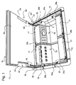
- figure 1 is an overall perspective view of a recessed floor-mounted tower according to the invention, in a state with the cover open;
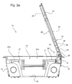
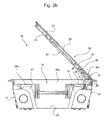
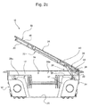
- figures 2a-2d are side views partially in section of the tower of figure 1 with the cover respectively in the open position, in two partially open positions and in the closed position;
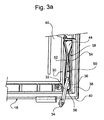
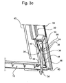
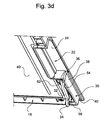
- figures 3a-3d show a detailed view of a braking device of the cover in the open, partially open and closed positions of figures 2a-2d;
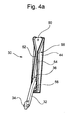
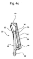
- figures 4a-4d show the elements making up the braking device illustrated in figures 3a-3d; and
- figure 5 shows a detail of a device for lifting the cover.
- In the figures, a recessed tower for floor-mounted electrical installations, comprising a
container body 12 adapted to define ahousing space 14 for modularelectrical devices 16, in general connection devices such as plug sockets, TV sockets, telephone connectors and EDP connectors, normally collected into device-holder supports 17, functionally similar to the supports used with wall-mounted boxes, is wholly indicated with 10. - The
housing space 14 is closed by acover 18 adapted to take up a closed position at the level of a treadable plane, like, for example, a raised or floating floor. - The
cover 18 is hinged to the container body at an edge thereof, and is adapted to take up a rotated open position, which in the currently preferred embodiment is a position near to the perpendicular arrangement with respect to the closed position, and in particular a position forming an acute angle, preferably 70°, with the closed position. - The cover is made with a rigid plastic structure and is provided, on the side facing towards the
housing space 14, with ametal reinforcement plate 20 of a width equal to the width of the cover and of a thickness equal to at least 2 mm, and preferably equal to 3 mm. - The cover has a pair of
side notches 22, adapted to allow the connection cables between an external device and an electrical device housed in the tower to pass through, which are closed on top, at the treadable surface, by asoft sealing insert 24, for example made from soft rubber, adapted to be removably coupled with the cover so as to be able to be replaced in the case of damage. Preferably, such an insert is provided with a plurality of ridges or ribs suitable for being forcibly inserted into respective guides formed on the plastic shape of the cover, to allow a coupling of the insert with the rigid structure of the cover that is as stable as possible, so as to prevent it from accidentally slipping away, for example due to prolonged treading on the cover. - The
container body 12 comprises abase wall 25 and a pair ofopposite side walls shoulders side walls base wall 25intermediate support formations 28c advantageously rise, in the form of middle partitions. - The
reinforcement plate 20 arranged on the side of the cover facing towards the housing space, allows the treadable cover to support heavy loads, in particular to support weights of up to a few hundreds of kilograms at the centre of the cover, avoiding elastic deformations of the structure of the cover and of the frame of the container body. In the closed position of the cover it rests upon the upper surfaces of theangular shoulders middle partitions 28c ensuring a better distribution of the loads on the structure of the tower (i.e. on the container body). - Moreover, the arrangement of the
plate 20 on the side of the cover facing towards thehousing space 14 ensures that it is - with the cover in closed position - entirely inside the space itself, thus substantially preventing it from uncovering and becoming accidentally exposed in the case of wear of the treadable coating of the cover with possible danger for the people or vehicles travelling on it. - Since the arrangement of the
metal reinforcement plate 20 substantially increases the weight of the cover, and its accidental closing could cause injury to an operator engaged in an intervention on the devices contained inside the tower, the tower is equipped with at least one braking device suitable for slowing down the cover in its closing travel. - In the currently preferred embodiment it is provided with a pair of
brake devices 30, arranged on opposite sides of the tower adjacent to the side in which the cover is hinged to the container body. - The individual braking device is described in detail here with reference to figures 3a-3d and 4a-4d, which respectively reproduce a portion of the structure of the
cover 18 without themetal plate 20 for the sake of ease of illustration, and a braking device cooperating with it in the open, partially open and closed positions, as well as the elements making up such a device. - The individual braking device comprises a
strut element 32 rotatably mounted, at a first end thereof 34, in ahousing seat 35 formed on thecontainer body 12 of the tower, preferably on the upper surfaces of theangular shoulders strut element 32 with the cover in closed position. On the opposite side to thearticulation end 34, theelement 32 has afree head 36 suitable for being received in a corresponding slidingseat 38 that is parallelepiped in shape, formed in theplastic structure 40 of the cover, and preferably in abutment on the base of theseat 38. - As highlighted in figure 1, the
reinforcement plate 20 of the cover hascorresponding slits 42 adapted to allow thestrut element 32 to pass through and move in its operating travel. - The sliding
seat 38 is provided, at least on its base surface, with acoating 44 of rubber or similar material adapted to have friction against the sliding of thehead 36 of thestrut element 32. - In the
seat 38, along the direction of translation of the head of the strut element, anelastic fork element 50 is also housed, comprising a pair of elasticallydeformable platens base 56, converging along a first section up to a point of maximum proximity orstricture 58 and then diverging in the final section. - In operation, the
braking device 30 is adapted to counteract the closing movement of the cover by the production of friction forces and elastic counteraction forces acting upon thestrut element 32. - In its closing movement, the
cover 18 pushes upon thestrut element 32 through thehead 36 cooperating with theseat 38, causing the rotation of the strut element around thearticulation end 34 until it is completely arranged in thehousing seat 35 in a rest position. During the course of such a movement, thehead 36 of the strut element slides in theseat 38 with friction by virtue of the contact with the coating of thebase 44, thus determining a first braking action, practically continuous along the entire closing travel of the cover. - In its sliding in the
seat 38, the head of the strut element laterally cooperates with theelastic platens fork element 50, forcing it to spread apart as, in its traverse in theseat 38, it moves closer to thestricture point 58, at the same time undergoing the elastic reaction force that acts to slow down the translation and consequently to brake the closing of the cover. - This second braking effect manifests itself with a sudden slowing down of the closing movement of the cover shortly after half of its closing travel.
- Advantageously, since the presence of the
reinforcement plate 20 increases the weight of the cover, the latter is provided with aretractable lifting device 60 formed on its treadable surface, preferably at the edge opposite the edge in which it is hinged to the container body. - With reference to figure 5, such a device comprises a
lever 62 rotatably mounted in aseat 64 formed on the treadable surface of the cover, adapted to take up a rest position in which it lies parallel to the cover and a use position in which it rises from the surface of the cover to allow it to be gripped by an operator. The lifting of the lever is made easier by the presence of arecess 66 for access to its seat, adapted to allow the introduction of a finger of an operator, and by making acorrugated portion 68 of its outer surface to make it easier to grip. - In a currently preferred embodiment, the seat for the lever also houses a locking device (not depicted) adapted to lock the cover in a closed state, comprising a latch that can translate between a position that allows it to be opened and a locking position through a key-operated actuation cylinder or, more simply, by means of a tool like a screwdriver.
- It should be noted that the embodiment proposed for the present invention in the above discussion is purely a non-limiting example. A man skilled in the art can easily carry out the present invention in different embodiments that do not however depart from the principles outlined here.
- This applies in particular as regards the possibility of inverting the arrangement of the braking device between container body and cover of the tower, by mounting the strut element in a housing seat formed on the cover and forming a sliding seat of its head in the plastic structure of the container body.
- Without affecting the principle of the invention, the embodiments and the embodying details can be widely varied with respect to what has been described and illustrated, without for this reason departing from the scope of protection of the present invention defined by the attached claims.
Claims (18)
- Tower for floor-mounted electrical installations, comprising a container body (12) adapted to define a housing space (14) for electrical devices (16) and a closing cover (18) adapted to be arranged, in a closed position, at the level of a treadable plane,
characterised in that said cover (18) includes a metal reinforcement plate (20) arranged on the side of the cover facing towards said housing space (14). - Tower according to claim 1, in which said container body (12) has angular support formations adapted to form a support for said metal plate (20), which include shoulder formations (28a, 28b) adjacent to side walls (26a, 26b) of said body (12) or integral therewith.
- Tower according to claim 1 or 2, in which said container body (12) has intermediate support formations adapted to form a support for said metal plate (20), which include middle partitions (28c) that rise from a base wall (25) of the container body (12).
- Tower according to any one of claims 1 to 3, in which said metal reinforcement plate (20) has a thickness at least equal to or greater than two millimetres.
- Tower according to claim 4, in which said metal reinforcement plate (20) has a thickness equal to three millimetres.
- Tower according to any one of the previous claims, characterised in that said closing cover (18) is hinged at an edge of said container body (12).
- Tower according to claim 6, in which said cover (18) is adapted to take up a rotated open position in which it forms an acute angle with respect to its closed position.
- Tower according to claim 6 or 7, comprising at least one braking device (30) adapted to slow down the cover (18) during the closing movement.
- Tower according to claim 8, in which said braking device (30) is arranged to counteract the closing movement of the cover (18) exerting a friction force.
- Tower according to claim 9, in which said braking device (30) comprises a strut element (32) rotatably coupled with said container body (12) (cover (18)) and adapted to cooperate with a surface of said cover (18) (container body (12)), exerting a braking action by friction against said surface.
- Tower according to claim 10, in which said strut element (32) has a first end (34) rotatably coupled with the container body (12), and in which said cover (18) has a sliding seat (38) adapted to receive a second free end (36) of the strut element (32), said braking action being exerted by friction between the free end (36) of the strut element (32) and said seat (38).
- Tower according to claim 11, in which said seat has (38) at least one rubber surface (44) for contact with the free end (36) of the strut element (32).
- Tower according to claim 11 or 12, in which said sliding seat (38) of the free end (36) of the strut element (32) has at least one elastically deformable element (50) arranged to exert an elastic counteraction force to the movement of said end (36) in the closing travel of the cover (18).
- Tower according to claim 13, in which said elastically deformable element (50) comprises at least one leaf spring (52, 54, 56) arranged so as to progressively narrow the section of said seat (38) in the direction in which the end (36) of the strut element (32) crosses said seat (38) in the closing travel of the cover (18).
- Tower according to any one of claims 9 to 14, comprising a pair of braking devices (30) arranged at opposite sides of the tower.
- Tower according to any one of the previous claims, in which said cover (18) is provided with at least one retractable lifting device (60).
- Tower according to claim 16, in which said lifting device (60) comprises a lever (62) rotatably mounted in a seat (64) formed on the treadable surface of the cover (18) and adapted to take up a rest position in which it is arranged parallel to the cover and a use position in which it rises from the surface of the cover to allow it to be gripped by an operator.
- Tower according to claim 17, in which the seat (64) of said lever (62) carries a locking device adapted to lock the cover in a closed condition.
Applications Claiming Priority (1)
| Application Number | Priority Date | Filing Date | Title |
|---|---|---|---|
| ITTO20050335 ITTO20050335A1 (en) | 2005-05-17 | 2005-05-17 | RETRACTABLE TURRET FOR ELECTRIC FLOOR INSTALLATIONS, WITH REINFORCED COVER |
Publications (3)
| Publication Number | Publication Date |
|---|---|
| EP1724894A2 true EP1724894A2 (en) | 2006-11-22 |
| EP1724894A3 EP1724894A3 (en) | 2010-06-23 |
| EP1724894B1 EP1724894B1 (en) | 2013-05-01 |
Family
ID=36649070
Family Applications (1)
| Application Number | Title | Priority Date | Filing Date |
|---|---|---|---|
| EP20060113986 Active EP1724894B1 (en) | 2005-05-17 | 2006-05-16 | Recessed tower for floor-mounted electrical installations, with reinforced cover |
Country Status (4)
| Country | Link |
|---|---|
| EP (1) | EP1724894B1 (en) |
| CR (1) | CR8393A (en) |
| IT (1) | ITTO20050335A1 (en) |
| MX (1) | MXPA06005521A (en) |
Cited By (2)
| Publication number | Priority date | Publication date | Assignee | Title |
|---|---|---|---|---|
| GB2450556A (en) * | 2007-06-29 | 2008-12-31 | Novar Ed & S Ltd | Service outlet floor box |
| WO2012160268A1 (en) | 2011-05-23 | 2012-11-29 | Legrand France | Access hatch to electrical appliances |
Family Cites Families (2)
| Publication number | Priority date | Publication date | Assignee | Title |
|---|---|---|---|---|
| SE9502383L (en) * | 1995-06-30 | 1996-11-25 | Thorsman & Co Ab | Hinge arrangement for a floor mounted socket |
| DE29712728U1 (en) * | 1997-07-18 | 1997-09-18 | Ackermann Albert Gmbh Co | Underfloor device insert with a hinged lid |
-
2005
- 2005-05-17 IT ITTO20050335 patent/ITTO20050335A1/en unknown
-
2006
- 2006-05-11 CR CR8393A patent/CR8393A/en unknown
- 2006-05-16 MX MXPA06005521 patent/MXPA06005521A/en active IP Right Grant
- 2006-05-16 EP EP20060113986 patent/EP1724894B1/en active Active
Non-Patent Citations (1)
| Title |
|---|
| None |
Cited By (2)
| Publication number | Priority date | Publication date | Assignee | Title |
|---|---|---|---|---|
| GB2450556A (en) * | 2007-06-29 | 2008-12-31 | Novar Ed & S Ltd | Service outlet floor box |
| WO2012160268A1 (en) | 2011-05-23 | 2012-11-29 | Legrand France | Access hatch to electrical appliances |
Also Published As
| Publication number | Publication date |
|---|---|
| EP1724894B1 (en) | 2013-05-01 |
| ITTO20050335A1 (en) | 2006-11-18 |
| EP1724894A3 (en) | 2010-06-23 |
| CR8393A (en) | 2007-03-08 |
| MXPA06005521A (en) | 2007-04-24 |
Similar Documents
| Publication | Publication Date | Title |
|---|---|---|
| US9035182B2 (en) | Floor box cover assembly | |
| US8921695B2 (en) | Latching floor box cover | |
| EP3235748A1 (en) | Foldable container | |
| CA2832063A1 (en) | Cover assembly for an electrical box | |
| US20130020813A1 (en) | Door latch assembly with movable lock plate | |
| KR19980702142A (en) | Slidable detachable connection generating device between movable barrier and barrier guide means | |
| EP1724894B1 (en) | Recessed tower for floor-mounted electrical installations, with reinforced cover | |
| CA2983000C (en) | Floor box cover | |
| CN102530688B (en) | Elevator equipment | |
| CN205692982U (en) | Cable clamp and comprise its bifurcation connector | |
| ITTO20060077A1 (en) | CONCEALED TURRET FOR ELECTRIC FLOOR INSTALLATIONS WITH REMOVABLE LID | |
| CN109650232B (en) | Elevator layer door lock device and elevator layer door device | |
| KR20080082879A (en) | Device for guiding a front door of elevator | |
| KR200489027Y1 (en) | A shock absorber of interlocking type door | |
| JP6022692B2 (en) | Elevator guide device | |
| EP2086065B1 (en) | Clasping device for the engagement with a suspended electrical duct | |
| JP4951424B2 (en) | Iron lid opening and closing device | |
| KR101333052B1 (en) | Slider mounting device for slide door | |
| CN207572773U (en) | A kind of box type substation door interlock | |
| JP7194617B2 (en) | pit cover | |
| JP5244252B1 (en) | Transport vehicle door device | |
| KR101380668B1 (en) | Door apparatus | |
| JP6400901B2 (en) | Rail vehicle sliding door structure | |
| CN213460240U (en) | Electric socket | |
| EP2891617A1 (en) | Insulating loading bay |
Legal Events
| Date | Code | Title | Description |
|---|---|---|---|
| PUAI | Public reference made under article 153(3) epc to a published international application that has entered the european phase |
Free format text: ORIGINAL CODE: 0009012 |
|
| AK | Designated contracting states |
Kind code of ref document: A2 Designated state(s): AT BE BG CH CY CZ DE DK EE ES FI FR GB GR HU IE IS IT LI LT LU LV MC NL PL PT RO SE SI SK TR |
|
| AX | Request for extension of the european patent |
Extension state: AL BA HR MK YU |
|
| PUAL | Search report despatched |
Free format text: ORIGINAL CODE: 0009013 |
|
| AK | Designated contracting states |
Kind code of ref document: A3 Designated state(s): AT BE BG CH CY CZ DE DK EE ES FI FR GB GR HU IE IS IT LI LT LU LV MC NL PL PT RO SE SI SK TR |
|
| AX | Request for extension of the european patent |
Extension state: AL BA HR MK YU |
|
| RIC1 | Information provided on ipc code assigned before grant |
Ipc: H02G 3/18 20060101ALI20100519BHEP Ipc: H02G 3/00 20060101AFI20060727BHEP |
|
| 17P | Request for examination filed |
Effective date: 20101223 |
|
| AKX | Designation fees paid |
Designated state(s): AT BE BG CH CY CZ DE DK EE ES FI FR GB GR HU IE IS IT LI LT LU LV MC NL PL PT RO SE SI SK TR |
|
| GRAP | Despatch of communication of intention to grant a patent |
Free format text: ORIGINAL CODE: EPIDOSNIGR1 |
|
| GRAS | Grant fee paid |
Free format text: ORIGINAL CODE: EPIDOSNIGR3 |
|
| GRAA | (expected) grant |
Free format text: ORIGINAL CODE: 0009210 |
|
| AK | Designated contracting states |
Kind code of ref document: B1 Designated state(s): AT BE BG CH CY CZ DE DK EE ES FI FR GB GR HU IE IS IT LI LT LU LV MC NL PL PT RO SE SI SK TR |
|
| REG | Reference to a national code |
Ref country code: GB Ref legal event code: FG4D |
|
| REG | Reference to a national code |
Ref country code: CH Ref legal event code: EP Ref country code: AT Ref legal event code: REF Ref document number: 610442 Country of ref document: AT Kind code of ref document: T Effective date: 20130515 |
|
| REG | Reference to a national code |
Ref country code: IE Ref legal event code: FG4D |
|
| REG | Reference to a national code |
Ref country code: DE Ref legal event code: R096 Ref document number: 602006035999 Country of ref document: DE Effective date: 20130704 |
|
| REG | Reference to a national code |
Ref country code: AT Ref legal event code: MK05 Ref document number: 610442 Country of ref document: AT Kind code of ref document: T Effective date: 20130501 |
|
| REG | Reference to a national code |
Ref country code: NL Ref legal event code: VDEP Effective date: 20130501 |
|
| REG | Reference to a national code |
Ref country code: LT Ref legal event code: MG4D |
|
| PG25 | Lapsed in a contracting state [announced via postgrant information from national office to epo] |
Ref country code: PT Free format text: LAPSE BECAUSE OF FAILURE TO SUBMIT A TRANSLATION OF THE DESCRIPTION OR TO PAY THE FEE WITHIN THE PRESCRIBED TIME-LIMIT Effective date: 20130902 Ref country code: GR Free format text: LAPSE BECAUSE OF FAILURE TO SUBMIT A TRANSLATION OF THE DESCRIPTION OR TO PAY THE FEE WITHIN THE PRESCRIBED TIME-LIMIT Effective date: 20130802 Ref country code: SE Free format text: LAPSE BECAUSE OF FAILURE TO SUBMIT A TRANSLATION OF THE DESCRIPTION OR TO PAY THE FEE WITHIN THE PRESCRIBED TIME-LIMIT Effective date: 20130501 Ref country code: LT Free format text: LAPSE BECAUSE OF FAILURE TO SUBMIT A TRANSLATION OF THE DESCRIPTION OR TO PAY THE FEE WITHIN THE PRESCRIBED TIME-LIMIT Effective date: 20130501 Ref country code: FI Free format text: LAPSE BECAUSE OF FAILURE TO SUBMIT A TRANSLATION OF THE DESCRIPTION OR TO PAY THE FEE WITHIN THE PRESCRIBED TIME-LIMIT Effective date: 20130501 Ref country code: AT Free format text: LAPSE BECAUSE OF FAILURE TO SUBMIT A TRANSLATION OF THE DESCRIPTION OR TO PAY THE FEE WITHIN THE PRESCRIBED TIME-LIMIT Effective date: 20130501 Ref country code: IS Free format text: LAPSE BECAUSE OF FAILURE TO SUBMIT A TRANSLATION OF THE DESCRIPTION OR TO PAY THE FEE WITHIN THE PRESCRIBED TIME-LIMIT Effective date: 20130901 Ref country code: SI Free format text: LAPSE BECAUSE OF FAILURE TO SUBMIT A TRANSLATION OF THE DESCRIPTION OR TO PAY THE FEE WITHIN THE PRESCRIBED TIME-LIMIT Effective date: 20130501 Ref country code: ES Free format text: LAPSE BECAUSE OF FAILURE TO SUBMIT A TRANSLATION OF THE DESCRIPTION OR TO PAY THE FEE WITHIN THE PRESCRIBED TIME-LIMIT Effective date: 20130812 |
|
| PG25 | Lapsed in a contracting state [announced via postgrant information from national office to epo] |
Ref country code: CY Free format text: LAPSE BECAUSE OF FAILURE TO SUBMIT A TRANSLATION OF THE DESCRIPTION OR TO PAY THE FEE WITHIN THE PRESCRIBED TIME-LIMIT Effective date: 20130501 Ref country code: BG Free format text: LAPSE BECAUSE OF FAILURE TO SUBMIT A TRANSLATION OF THE DESCRIPTION OR TO PAY THE FEE WITHIN THE PRESCRIBED TIME-LIMIT Effective date: 20130801 Ref country code: PL Free format text: LAPSE BECAUSE OF FAILURE TO SUBMIT A TRANSLATION OF THE DESCRIPTION OR TO PAY THE FEE WITHIN THE PRESCRIBED TIME-LIMIT Effective date: 20130501 |
|
| PG25 | Lapsed in a contracting state [announced via postgrant information from national office to epo] |
Ref country code: LV Free format text: LAPSE BECAUSE OF FAILURE TO SUBMIT A TRANSLATION OF THE DESCRIPTION OR TO PAY THE FEE WITHIN THE PRESCRIBED TIME-LIMIT Effective date: 20130501 |
|
| REG | Reference to a national code |
Ref country code: CH Ref legal event code: PL |
|
| PG25 | Lapsed in a contracting state [announced via postgrant information from national office to epo] |
Ref country code: CH Free format text: LAPSE BECAUSE OF NON-PAYMENT OF DUE FEES Effective date: 20130531 Ref country code: DK Free format text: LAPSE BECAUSE OF FAILURE TO SUBMIT A TRANSLATION OF THE DESCRIPTION OR TO PAY THE FEE WITHIN THE PRESCRIBED TIME-LIMIT Effective date: 20130501 Ref country code: EE Free format text: LAPSE BECAUSE OF FAILURE TO SUBMIT A TRANSLATION OF THE DESCRIPTION OR TO PAY THE FEE WITHIN THE PRESCRIBED TIME-LIMIT Effective date: 20130501 Ref country code: SK Free format text: LAPSE BECAUSE OF FAILURE TO SUBMIT A TRANSLATION OF THE DESCRIPTION OR TO PAY THE FEE WITHIN THE PRESCRIBED TIME-LIMIT Effective date: 20130501 Ref country code: DE Free format text: LAPSE BECAUSE OF NON-PAYMENT OF DUE FEES Effective date: 20131203 Ref country code: CZ Free format text: LAPSE BECAUSE OF FAILURE TO SUBMIT A TRANSLATION OF THE DESCRIPTION OR TO PAY THE FEE WITHIN THE PRESCRIBED TIME-LIMIT Effective date: 20130501 Ref country code: LI Free format text: LAPSE BECAUSE OF NON-PAYMENT OF DUE FEES Effective date: 20130531 Ref country code: MC Free format text: LAPSE BECAUSE OF FAILURE TO SUBMIT A TRANSLATION OF THE DESCRIPTION OR TO PAY THE FEE WITHIN THE PRESCRIBED TIME-LIMIT Effective date: 20130501 Ref country code: BE Free format text: LAPSE BECAUSE OF FAILURE TO SUBMIT A TRANSLATION OF THE DESCRIPTION OR TO PAY THE FEE WITHIN THE PRESCRIBED TIME-LIMIT Effective date: 20130501 |
|
| REG | Reference to a national code |
Ref country code: IE Ref legal event code: MM4A |
|
| REG | Reference to a national code |
Ref country code: DE Ref legal event code: R119 Ref document number: 602006035999 Country of ref document: DE Effective date: 20131203 |
|
| PG25 | Lapsed in a contracting state [announced via postgrant information from national office to epo] |
Ref country code: RO Free format text: LAPSE BECAUSE OF FAILURE TO SUBMIT A TRANSLATION OF THE DESCRIPTION OR TO PAY THE FEE WITHIN THE PRESCRIBED TIME-LIMIT Effective date: 20130501 Ref country code: NL Free format text: LAPSE BECAUSE OF FAILURE TO SUBMIT A TRANSLATION OF THE DESCRIPTION OR TO PAY THE FEE WITHIN THE PRESCRIBED TIME-LIMIT Effective date: 20130501 |
|
| PLBE | No opposition filed within time limit |
Free format text: ORIGINAL CODE: 0009261 |
|
| STAA | Information on the status of an ep patent application or granted ep patent |
Free format text: STATUS: NO OPPOSITION FILED WITHIN TIME LIMIT |
|
| 26N | No opposition filed |
Effective date: 20140204 |
|
| GBPC | Gb: european patent ceased through non-payment of renewal fee |
Effective date: 20130801 |
|
| PG25 | Lapsed in a contracting state [announced via postgrant information from national office to epo] |
Ref country code: IE Free format text: LAPSE BECAUSE OF NON-PAYMENT OF DUE FEES Effective date: 20130516 |
|
| PG25 | Lapsed in a contracting state [announced via postgrant information from national office to epo] |
Ref country code: GB Free format text: LAPSE BECAUSE OF NON-PAYMENT OF DUE FEES Effective date: 20130801 |
|
| PG25 | Lapsed in a contracting state [announced via postgrant information from national office to epo] |
Ref country code: TR Free format text: LAPSE BECAUSE OF FAILURE TO SUBMIT A TRANSLATION OF THE DESCRIPTION OR TO PAY THE FEE WITHIN THE PRESCRIBED TIME-LIMIT Effective date: 20130501 |
|
| PG25 | Lapsed in a contracting state [announced via postgrant information from national office to epo] |
Ref country code: LU Free format text: LAPSE BECAUSE OF NON-PAYMENT OF DUE FEES Effective date: 20130516 Ref country code: HU Free format text: LAPSE BECAUSE OF FAILURE TO SUBMIT A TRANSLATION OF THE DESCRIPTION OR TO PAY THE FEE WITHIN THE PRESCRIBED TIME-LIMIT; INVALID AB INITIO Effective date: 20060516 |
|
| REG | Reference to a national code |
Ref country code: FR Ref legal event code: PLFP Year of fee payment: 11 |
|
| REG | Reference to a national code |
Ref country code: FR Ref legal event code: PLFP Year of fee payment: 12 |
|
| REG | Reference to a national code |
Ref country code: FR Ref legal event code: PLFP Year of fee payment: 13 |
|
| PGFP | Annual fee paid to national office [announced via postgrant information from national office to epo] |
Ref country code: FR Payment date: 20210421 Year of fee payment: 16 |
|
| PG25 | Lapsed in a contracting state [announced via postgrant information from national office to epo] |
Ref country code: FR Free format text: LAPSE BECAUSE OF NON-PAYMENT OF DUE FEES Effective date: 20220531 |
|
| PGFP | Annual fee paid to national office [announced via postgrant information from national office to epo] |
Ref country code: IT Payment date: 20230420 Year of fee payment: 18 |