EP1724541A1 - Food temperature setting using RFID technology - Google Patents
Food temperature setting using RFID technology Download PDFInfo
- Publication number
- EP1724541A1 EP1724541A1 EP05445035A EP05445035A EP1724541A1 EP 1724541 A1 EP1724541 A1 EP 1724541A1 EP 05445035 A EP05445035 A EP 05445035A EP 05445035 A EP05445035 A EP 05445035A EP 1724541 A1 EP1724541 A1 EP 1724541A1
- Authority
- EP
- European Patent Office
- Prior art keywords
- compartment
- appliance according
- climate
- control unit
- user interface
- Prior art date
- Legal status (The legal status is an assumption and is not a legal conclusion. Google has not performed a legal analysis and makes no representation as to the accuracy of the status listed.)
- Withdrawn
Links
Images



Classifications
-
- F—MECHANICAL ENGINEERING; LIGHTING; HEATING; WEAPONS; BLASTING
- F25—REFRIGERATION OR COOLING; COMBINED HEATING AND REFRIGERATION SYSTEMS; HEAT PUMP SYSTEMS; MANUFACTURE OR STORAGE OF ICE; LIQUEFACTION SOLIDIFICATION OF GASES
- F25D—REFRIGERATORS; COLD ROOMS; ICE-BOXES; COOLING OR FREEZING APPARATUS NOT OTHERWISE PROVIDED FOR
- F25D29/00—Arrangement or mounting of control or safety devices
-
- F—MECHANICAL ENGINEERING; LIGHTING; HEATING; WEAPONS; BLASTING
- F25—REFRIGERATION OR COOLING; COMBINED HEATING AND REFRIGERATION SYSTEMS; HEAT PUMP SYSTEMS; MANUFACTURE OR STORAGE OF ICE; LIQUEFACTION SOLIDIFICATION OF GASES
- F25D—REFRIGERATORS; COLD ROOMS; ICE-BOXES; COOLING OR FREEZING APPARATUS NOT OTHERWISE PROVIDED FOR
- F25D29/00—Arrangement or mounting of control or safety devices
- F25D29/005—Mounting of control devices
-
- F—MECHANICAL ENGINEERING; LIGHTING; HEATING; WEAPONS; BLASTING
- F25—REFRIGERATION OR COOLING; COMBINED HEATING AND REFRIGERATION SYSTEMS; HEAT PUMP SYSTEMS; MANUFACTURE OR STORAGE OF ICE; LIQUEFACTION SOLIDIFICATION OF GASES
- F25D—REFRIGERATORS; COLD ROOMS; ICE-BOXES; COOLING OR FREEZING APPARATUS NOT OTHERWISE PROVIDED FOR
- F25D17/00—Arrangements for circulating cooling fluids; Arrangements for circulating gas, e.g. air, within refrigerated spaces
- F25D17/04—Arrangements for circulating cooling fluids; Arrangements for circulating gas, e.g. air, within refrigerated spaces for circulating air, e.g. by convection
-
- F—MECHANICAL ENGINEERING; LIGHTING; HEATING; WEAPONS; BLASTING
- F25—REFRIGERATION OR COOLING; COMBINED HEATING AND REFRIGERATION SYSTEMS; HEAT PUMP SYSTEMS; MANUFACTURE OR STORAGE OF ICE; LIQUEFACTION SOLIDIFICATION OF GASES
- F25D—REFRIGERATORS; COLD ROOMS; ICE-BOXES; COOLING OR FREEZING APPARATUS NOT OTHERWISE PROVIDED FOR
- F25D23/00—General constructional features
- F25D23/02—Doors; Covers
-
- G—PHYSICS
- G06—COMPUTING OR CALCULATING; COUNTING
- G06K—GRAPHICAL DATA READING; PRESENTATION OF DATA; RECORD CARRIERS; HANDLING RECORD CARRIERS
- G06K19/00—Record carriers for use with machines and with at least a part designed to carry digital markings
- G06K19/06—Record carriers for use with machines and with at least a part designed to carry digital markings characterised by the kind of the digital marking, e.g. shape, nature, code
- G06K19/067—Record carriers with conductive marks, printed circuits or semiconductor circuit elements, e.g. credit or identity cards also with resonating or responding marks without active components
- G06K19/07—Record carriers with conductive marks, printed circuits or semiconductor circuit elements, e.g. credit or identity cards also with resonating or responding marks without active components with integrated circuit chips
- G06K19/077—Constructional details, e.g. mounting of circuits in the carrier
-
- G—PHYSICS
- G06—COMPUTING OR CALCULATING; COUNTING
- G06K—GRAPHICAL DATA READING; PRESENTATION OF DATA; RECORD CARRIERS; HANDLING RECORD CARRIERS
- G06K19/00—Record carriers for use with machines and with at least a part designed to carry digital markings
- G06K19/06—Record carriers for use with machines and with at least a part designed to carry digital markings characterised by the kind of the digital marking, e.g. shape, nature, code
- G06K19/067—Record carriers with conductive marks, printed circuits or semiconductor circuit elements, e.g. credit or identity cards also with resonating or responding marks without active components
- G06K19/07—Record carriers with conductive marks, printed circuits or semiconductor circuit elements, e.g. credit or identity cards also with resonating or responding marks without active components with integrated circuit chips
- G06K19/077—Constructional details, e.g. mounting of circuits in the carrier
- G06K19/0772—Physical layout of the record carrier
- G06K19/07735—Physical layout of the record carrier the record carrier comprising means for protecting against electrostatic discharge
-
- F—MECHANICAL ENGINEERING; LIGHTING; HEATING; WEAPONS; BLASTING
- F25—REFRIGERATION OR COOLING; COMBINED HEATING AND REFRIGERATION SYSTEMS; HEAT PUMP SYSTEMS; MANUFACTURE OR STORAGE OF ICE; LIQUEFACTION SOLIDIFICATION OF GASES
- F25B—REFRIGERATION MACHINES, PLANTS OR SYSTEMS; COMBINED HEATING AND REFRIGERATION SYSTEMS; HEAT PUMP SYSTEMS
- F25B2600/00—Control issues
- F25B2600/07—Remote controls
-
- F—MECHANICAL ENGINEERING; LIGHTING; HEATING; WEAPONS; BLASTING
- F25—REFRIGERATION OR COOLING; COMBINED HEATING AND REFRIGERATION SYSTEMS; HEAT PUMP SYSTEMS; MANUFACTURE OR STORAGE OF ICE; LIQUEFACTION SOLIDIFICATION OF GASES
- F25B—REFRIGERATION MACHINES, PLANTS OR SYSTEMS; COMBINED HEATING AND REFRIGERATION SYSTEMS; HEAT PUMP SYSTEMS
- F25B2700/00—Sensing or detecting of parameters; Sensors therefor
- F25B2700/02—Humidity
-
- F—MECHANICAL ENGINEERING; LIGHTING; HEATING; WEAPONS; BLASTING
- F25—REFRIGERATION OR COOLING; COMBINED HEATING AND REFRIGERATION SYSTEMS; HEAT PUMP SYSTEMS; MANUFACTURE OR STORAGE OF ICE; LIQUEFACTION SOLIDIFICATION OF GASES
- F25D—REFRIGERATORS; COLD ROOMS; ICE-BOXES; COOLING OR FREEZING APPARATUS NOT OTHERWISE PROVIDED FOR
- F25D17/00—Arrangements for circulating cooling fluids; Arrangements for circulating gas, e.g. air, within refrigerated spaces
- F25D17/04—Arrangements for circulating cooling fluids; Arrangements for circulating gas, e.g. air, within refrigerated spaces for circulating air, e.g. by convection
- F25D17/042—Air treating means within refrigerated spaces
-
- F—MECHANICAL ENGINEERING; LIGHTING; HEATING; WEAPONS; BLASTING
- F25—REFRIGERATION OR COOLING; COMBINED HEATING AND REFRIGERATION SYSTEMS; HEAT PUMP SYSTEMS; MANUFACTURE OR STORAGE OF ICE; LIQUEFACTION SOLIDIFICATION OF GASES
- F25D—REFRIGERATORS; COLD ROOMS; ICE-BOXES; COOLING OR FREEZING APPARATUS NOT OTHERWISE PROVIDED FOR
- F25D23/00—General constructional features
- F25D23/02—Doors; Covers
- F25D23/025—Secondary closures
-
- F—MECHANICAL ENGINEERING; LIGHTING; HEATING; WEAPONS; BLASTING
- F25—REFRIGERATION OR COOLING; COMBINED HEATING AND REFRIGERATION SYSTEMS; HEAT PUMP SYSTEMS; MANUFACTURE OR STORAGE OF ICE; LIQUEFACTION SOLIDIFICATION OF GASES
- F25D—REFRIGERATORS; COLD ROOMS; ICE-BOXES; COOLING OR FREEZING APPARATUS NOT OTHERWISE PROVIDED FOR
- F25D2317/00—Details or arrangements for circulating cooling fluids; Details or arrangements for circulating gas, e.g. air, within refrigerated spaces, not provided for in other groups of this subclass
- F25D2317/06—Details or arrangements for circulating cooling fluids; Details or arrangements for circulating gas, e.g. air, within refrigerated spaces, not provided for in other groups of this subclass with forced air circulation
- F25D2317/061—Details or arrangements for circulating cooling fluids; Details or arrangements for circulating gas, e.g. air, within refrigerated spaces, not provided for in other groups of this subclass with forced air circulation through special compartments
-
- F—MECHANICAL ENGINEERING; LIGHTING; HEATING; WEAPONS; BLASTING
- F25—REFRIGERATION OR COOLING; COMBINED HEATING AND REFRIGERATION SYSTEMS; HEAT PUMP SYSTEMS; MANUFACTURE OR STORAGE OF ICE; LIQUEFACTION SOLIDIFICATION OF GASES
- F25D—REFRIGERATORS; COLD ROOMS; ICE-BOXES; COOLING OR FREEZING APPARATUS NOT OTHERWISE PROVIDED FOR
- F25D2400/00—General features of, or devices for refrigerators, cold rooms, ice-boxes, or for cooling or freezing apparatus not covered by any other subclass
- F25D2400/36—Visual displays
- F25D2400/361—Interactive visual displays
-
- F—MECHANICAL ENGINEERING; LIGHTING; HEATING; WEAPONS; BLASTING
- F25—REFRIGERATION OR COOLING; COMBINED HEATING AND REFRIGERATION SYSTEMS; HEAT PUMP SYSTEMS; MANUFACTURE OR STORAGE OF ICE; LIQUEFACTION SOLIDIFICATION OF GASES
- F25D—REFRIGERATORS; COLD ROOMS; ICE-BOXES; COOLING OR FREEZING APPARATUS NOT OTHERWISE PROVIDED FOR
- F25D25/00—Charging, supporting, and discharging the articles to be cooled
- F25D25/02—Charging, supporting, and discharging the articles to be cooled by shelves
- F25D25/024—Slidable shelves
- F25D25/025—Drawers
-
- F—MECHANICAL ENGINEERING; LIGHTING; HEATING; WEAPONS; BLASTING
- F25—REFRIGERATION OR COOLING; COMBINED HEATING AND REFRIGERATION SYSTEMS; HEAT PUMP SYSTEMS; MANUFACTURE OR STORAGE OF ICE; LIQUEFACTION SOLIDIFICATION OF GASES
- F25D—REFRIGERATORS; COLD ROOMS; ICE-BOXES; COOLING OR FREEZING APPARATUS NOT OTHERWISE PROVIDED FOR
- F25D2700/00—Means for sensing or measuring; Sensors therefor
- F25D2700/08—Sensors using Radio Frequency Identification [RFID]
-
- F—MECHANICAL ENGINEERING; LIGHTING; HEATING; WEAPONS; BLASTING
- F25—REFRIGERATION OR COOLING; COMBINED HEATING AND REFRIGERATION SYSTEMS; HEAT PUMP SYSTEMS; MANUFACTURE OR STORAGE OF ICE; LIQUEFACTION SOLIDIFICATION OF GASES
- F25D—REFRIGERATORS; COLD ROOMS; ICE-BOXES; COOLING OR FREEZING APPARATUS NOT OTHERWISE PROVIDED FOR
- F25D2700/00—Means for sensing or measuring; Sensors therefor
- F25D2700/12—Sensors measuring the inside temperature
- F25D2700/121—Sensors measuring the inside temperature of particular compartments
-
- H—ELECTRICITY
- H01—ELECTRIC ELEMENTS
- H01H—ELECTRIC SWITCHES; RELAYS; SELECTORS; EMERGENCY PROTECTIVE DEVICES
- H01H2207/00—Connections
- H01H2207/048—Inductive or infrared coupling
-
- H—ELECTRICITY
- H01—ELECTRIC ELEMENTS
- H01H—ELECTRIC SWITCHES; RELAYS; SELECTORS; EMERGENCY PROTECTIVE DEVICES
- H01H2219/00—Legends
- H01H2219/002—Legends replaceable; adaptable
-
- H—ELECTRICITY
- H01—ELECTRIC ELEMENTS
- H01H—ELECTRIC SWITCHES; RELAYS; SELECTORS; EMERGENCY PROTECTIVE DEVICES
- H01H2223/00—Casings
- H01H2223/01—Mounting on appliance
- H01H2223/018—Mounting on appliance rotatably
-
- H—ELECTRICITY
- H01—ELECTRIC ELEMENTS
- H01H—ELECTRIC SWITCHES; RELAYS; SELECTORS; EMERGENCY PROTECTIVE DEVICES
- H01H2300/00—Orthogonal indexing scheme relating to electric switches, relays, selectors or emergency protective devices covered by H01H
- H01H2300/03—Application domotique, e.g. for house automation, bus connected switches, sensors, loads or intelligent wiring
- H01H2300/032—Application domotique, e.g. for house automation, bus connected switches, sensors, loads or intelligent wiring using RFID technology in switching devices
-
- Y—GENERAL TAGGING OF NEW TECHNOLOGICAL DEVELOPMENTS; GENERAL TAGGING OF CROSS-SECTIONAL TECHNOLOGIES SPANNING OVER SEVERAL SECTIONS OF THE IPC; TECHNICAL SUBJECTS COVERED BY FORMER USPC CROSS-REFERENCE ART COLLECTIONS [XRACs] AND DIGESTS
- Y02—TECHNOLOGIES OR APPLICATIONS FOR MITIGATION OR ADAPTATION AGAINST CLIMATE CHANGE
- Y02B—CLIMATE CHANGE MITIGATION TECHNOLOGIES RELATED TO BUILDINGS, e.g. HOUSING, HOUSE APPLIANCES OR RELATED END-USER APPLICATIONS
- Y02B90/00—Enabling technologies or technologies with a potential or indirect contribution to GHG emissions mitigation
- Y02B90/20—Smart grids as enabling technology in buildings sector
-
- Y—GENERAL TAGGING OF NEW TECHNOLOGICAL DEVELOPMENTS; GENERAL TAGGING OF CROSS-SECTIONAL TECHNOLOGIES SPANNING OVER SEVERAL SECTIONS OF THE IPC; TECHNICAL SUBJECTS COVERED BY FORMER USPC CROSS-REFERENCE ART COLLECTIONS [XRACs] AND DIGESTS
- Y04—INFORMATION OR COMMUNICATION TECHNOLOGIES HAVING AN IMPACT ON OTHER TECHNOLOGY AREAS
- Y04S—SYSTEMS INTEGRATING TECHNOLOGIES RELATED TO POWER NETWORK OPERATION, COMMUNICATION OR INFORMATION TECHNOLOGIES FOR IMPROVING THE ELECTRICAL POWER GENERATION, TRANSMISSION, DISTRIBUTION, MANAGEMENT OR USAGE, i.e. SMART GRIDS
- Y04S20/00—Management or operation of end-user stationary applications or the last stages of power distribution; Controlling, monitoring or operating thereof
- Y04S20/14—Protecting elements, switches, relays or circuit breakers
Definitions
- the present invention relates to an appliance having a storage compartment with an opening for access into the compartment.
- a cover is being arranged for covering the opening in order to enclose the compartment.
- the apparatus further comprising a climate control system being provided to control the climate inside the compartment, the system comprising a control unit for control and adjustment of climate parameters of the compartment.
- the system further comprises means to detect the parameters.
- the cabinet comprises at least one compartment for which the temperature needs to be controlled. Most common is to control the temperature, but it might also happen that other climate parameters, such as air humidity, is controlled.
- US patent US6170276 from Maytag Corporation discloses a cooling cabinet wherein the cabinet comprises some compartment in which the climate is controlled. As shown there is at least one compartment 30 where the climate is specifically controlled.
- a climate device indicated with a fan 71 and inlet/outlet 76/77, makes the adjustment of the climate parameters based on information from a control unit 58.
- the control system further comprises means, such as temperature and humidity sensors connected to the control unit, to detect the climate inside the compartment.
- the compartment therefore comprises means to provide such a wishful storage. For instance should the walls be isolated from the rest of the compartment and the control system needs to be sufficient enough to enable the climate control.
- an object of the present invention is to provide a more consumer innovative solution, meaning a solution that understands the needs of the user. Moreover, an object of the present invention is to provide a solution that is cheaper and easier to industrialize.
- the present invention relates to an appliance having a storage compartment with a opening for access into the compartment.
- a cover is being arranged for covering the opening in order to enclose the compartment.
- the apparatus further comprising a climate control system being provided to control the climate inside the compartment, the system comprising a control unit for control and adjustment of climate parameters of the compartment.
- the system further comprises means to detect the parameters.
- the system comprises a user interface enabling the user to determine the operation of the system.
- the user interface is being arranged on the cover and comprises a limited number of functions for the determination. Each of the functions corresponds to a defined set of values of the climate parameters.
- FIGS. 1-10 show an illustrative embodiment of an appliance with a compartment having a climate control system in accordance with the invention.
- the illustrative embodiment shall not be interpreted as a limitation of the invention. Its purpose is to illustrate how the invention can be applied and to further illustrate the scope of the invention.
- Fig. 1 shows a front perspective view of a cooling cabinet 10 in which a compartment 11 with a climate control system is integrated.
- the figure only illustrates the basic concepts of the technical field, which is climate-controlled compartment. This means that the person skilled in the art should not read the specification and the accompanying drawings as a strict limitation of the scope of the invention, which in fact relates to the features of the climate control system, see fig. 2 - 5.
- Fig. 1 illustrates how the cooling cabinet 10, having a regular cooling system of some kind, and the compartment 11 could cooperate.
- air is provided to flow between the cooling compartment 12 of the cooling cabinet and the inside 13 of the compartment.
- the flow is illustrated with arrows, flow from the compartment 12 to the inside 13 by arrows 14 and flow from the inside to the compartment 12 by arrows 15.
- a climate device such as this is, as part of the climate control system, enables the airflow.
- Such as device preferably comprises at least one fan and/or a damper (not shown).
- the compartment 11 comprises surrounding walls 16 and an opening 17. Moreover, a cover 18 is arranged for covering the opening in order to enclose the compartment.
- the cover of the illustrative embodiment is preferably part of a receptacle that is slidably mounted at the compartment, in order to be able to slide as a drawer in and out of the compartment.
- the complete receptacle is not shown in the drawings, since it is not essential for the present invention and since it is part of common knowledge.
- Arrow 19 illustrates how the cover of the illustrative embodiment can move during use.
- the cover could be a door or lid hinged at the compartment. This means that the cover design is not essential for the present invention.
- Fig. 2 shows a front perspective view of the compartment 11 in which the climate control system is further illustrated.
- the surrounding walls 16 and the cover 17 are shown.
- the climate control system is shown.
- the task for this system is to control the climate parameters, such as temperature and air humidity, inside the compartment.
- the system comprises some parts.
- a control unit 20 preferable as a PCB board with a microcomputer.
- the control unit could be separate and unique for this compartment or part of a larger control system for more compartments and/or the whole cooling cabinet.
- the control unit 20 is connected to sensors or probes, in the illustrative embodiment one temperature sensor 21 and one air humidity sensor 22. These provide information to the control unit about the values of the climate parameters inside the compartment 11. They are for instance connected to the control unit by wire connections 35 or wireless.
- the compartment further comprises a user interface 23 mounted on the cover 18 and an antenna 24 mounted at the lower part of the compartment. The antenna could as an alternative be arranged at the top of the compartment or somewhere else preferable for the operations of the compartment or the whole cabinet.
- the user interface is the most essential part of the present invention and will therefore be described in detail in relation to fig. 3 - 5.
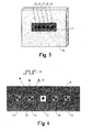
- Fig. 3 shows a front perspective view of the cover 18 of the compartment in which the user interface is further illustrated, while fig. 4 shows in a front view the user interface in a more detailed view.
- the main idea having a user interface for this kind of climate control system is to enable for the user to determine the operation of the system. This means that the user can set the values of the climate parameters. For instance, if the user wishes to have a setting of 2 degree Celsius temperature and 70% air humidity inside the compartment 11 he/she determines the values on the interface and the control system will make sure to adjust the climate inside the compartment to enable the determined parameter values.
- the user interface of the present invention intends to solve this problem.
- the user interface is provided with five functions, illustrated by numbers 25 - 29, for user determination.
- Each of these functions corresponds to a defined setting of values for the climate parameters.
- one function 25 corresponds to a setting of 2 degree Celsius temperature and 70% air humidity.
- Another function 29 for instance corresponds to a setting of 0 degree Celsius temperature and 50% air humidity. This means that the user does not need to know the actual settings. Instead he/she selects one of five functions and the climate control system does the rest.
- each function has a symbol (printed or electronically displayed). The star of function 27 illustrates such a symbol.
- the picture of specific provisions, such as a vegetable is shown (see fig. 4).
- Radio Frequency Identifiers These small electronic circuits does not need any energy supply and can transmit a digital code to identify itself. Depending on the frequency in which the RFID works it can transmit more or less complex signals.
- the RFID also comprises some kind of antenna, such as a coil, which can receive magnetic or electrical field signals and use these to energize the RFID and thereby be able to transmit the digital code. In the future it is also expected that the energy RFID receives can be user to do more than transmit a digital code.
- RFID is a very convenient technique to use in the present invention.
- the basic principle is to arrange one unique RFID 25 - 29 at each function symbol of the cover.
- Each unique RFID has its own digital code.
- one of the functions, 26, is illustrated with an RFID 30.
- the arrows 31 illustrate the radio frequency signal sent out when the RFID is energized while the symbol 35 illustrates the digital code carried by the frequency sent.
- the climate control system uses the antenna 24, see fig. 2, both to energize the RFID:s and to receive the radio frequency signals transmitted back. It will therefore either "see” the RFID continuously or on regular basis ask for (shake hand) with the RFID circuits by energizing them. Having the communication, it will be possible to communicate the function selected by the user to the control unit.
- the present invention uses shielding to enable this, as illustrated in fig. 5.
- Fig. 5 shows a front perspective view of the principle idea for the user interface of the illustrative embodiment.
- the user interface further comprises a mechanism with a moving part 32 being able to indicate the function 25 - 29 determined by the user.
- the figure also shows the symbol (the star) of number 27 function.
- the mechanism of the embodiment comprises a sliding frame 33, see fig. 4, which supports the moving part. Of course a rotating or any other mechanism can be used instead to enable to same function.
- the position of the moving part can by indicated in many ways, which is why the illustrative embodiment does not describe any particular indication. One way could be to have a frame indicating the symbol selected. Another way could be to energize light means on the RFID lightning up or change color of the symbol selected.
- the idea with a moving part 32 is that when it is positioned at an RFID, the signals to and from this RFID will be shielded off. This means that the climate control system will no "see” this RFID. Still it sees the other four RFID:s. This means that the system will easily determine which function the user has selected and activate the adjustments needed to change the climate in accordance with the function.
- the arrow 34 illustrates the sliding function.
- the user interface is arranged on the cover 19 and that it comprises a limited number of functions (25-29) for the users determination of the systems operation.
Landscapes
- Engineering & Computer Science (AREA)
- Physics & Mathematics (AREA)
- Chemical & Material Sciences (AREA)
- Combustion & Propulsion (AREA)
- Mechanical Engineering (AREA)
- Thermal Sciences (AREA)
- General Engineering & Computer Science (AREA)
- Microelectronics & Electronic Packaging (AREA)
- Computer Hardware Design (AREA)
- General Physics & Mathematics (AREA)
- Theoretical Computer Science (AREA)
- Cold Air Circulating Systems And Constructional Details In Refrigerators (AREA)
- Devices That Are Associated With Refrigeration Equipment (AREA)
- Air Conditioning Control Device (AREA)
- Electric Ovens (AREA)
- Selective Calling Equipment (AREA)
Abstract
Description
- The present invention relates to an appliance having a storage compartment with an opening for access into the compartment. A cover is being arranged for covering the opening in order to enclose the compartment. The apparatus further comprising a climate control system being provided to control the climate inside the compartment, the system comprising a control unit for control and adjustment of climate parameters of the compartment. The system further comprises means to detect the parameters.
- Systems to control the climate inside a compartment are well known. For instance in the area of cooling cabinets, for instance refrigerators or freezers, the cabinet comprises at least one compartment for which the temperature needs to be controlled. Most common is to control the temperature, but it might also happen that other climate parameters, such as air humidity, is controlled.
-
US patent US6170276 from Maytag Corporation discloses a cooling cabinet wherein the cabinet comprises some compartment in which the climate is controlled. As shown there is at least onecompartment 30 where the climate is specifically controlled. A climate device, indicated with a fan 71 and inlet/outlet 76/77, makes the adjustment of the climate parameters based on information from a control unit 58. The control system further comprises means, such as temperature and humidity sensors connected to the control unit, to detect the climate inside the compartment. - As mentioned is said patent there is a great need by consumers to store fruit and vegetables or other provisions in a separate storage compartment in order to be able to provide the most sufficient storage climate for this specific provisions. The compartment therefore comprises means to provide such a wishful storage. For instance should the walls be isolated from the rest of the compartment and the control system needs to be sufficient enough to enable the climate control.
- One problem with the disclosed solution by Maytag and many other solutions is that the control unit is very complex to handle. The user is in most cases not aware of the proper settings for specific provisions and will have problems to handle the buttons of the disclosed user interface. Another problem is that the user interface is arranged in a very inconvenient position. It is difficult for the user to be able to bend down and try to read and understand the user interface when it is positioned like that at a small unit next to the drawer cover. Moreover, one problem with the Maytag solution in that the user interface demands space, which results in a decreased volume for the provisions compartment.
- Therefore an object of the present invention is to provide a more consumer innovative solution, meaning a solution that understands the needs of the user. Moreover, an object of the present invention is to provide a solution that is cheaper and easier to industrialize.
- The present invention relates to an appliance having a storage compartment with a opening for access into the compartment. A cover is being arranged for covering the opening in order to enclose the compartment. The apparatus further comprising a climate control system being provided to control the climate inside the compartment, the system comprising a control unit for control and adjustment of climate parameters of the compartment. The system further comprises means to detect the parameters.
- Furthermore, the system comprises a user interface enabling the user to determine the operation of the system. The user interface is being arranged on the cover and comprises a limited number of functions for the determination. Each of the functions corresponds to a defined set of values of the climate parameters.
- The invention will now be described further with reference to the accompanying drawings, in which:
- Fig. 1 shows a front perspective view of a cooling cabinet in which a compartment with a climate control system is integrated.
- Fig. 2 shows a front perspective view of the compartment according to fig. 1 in which the climate control system is further illustrated.
- Fig. 3 shows a front perspective view of the cover of the compartment according to fig. 1 - 2 in which the user interface is further illustrated.
- Fig. 4 shows in a front view the user interface of fig. 3 in a more detailed view.
- Fig. 5 shows a front perspective view of the determination mechanism of the user interface.
- The figures show an illustrative embodiment of an appliance with a compartment having a climate control system in accordance with the invention. The illustrative embodiment shall not be interpreted as a limitation of the invention. Its purpose is to illustrate how the invention can be applied and to further illustrate the scope of the invention.
- Fig. 1 shows a front perspective view of a
cooling cabinet 10 in which acompartment 11 with a climate control system is integrated. The figure only illustrates the basic concepts of the technical field, which is climate-controlled compartment. This means that the person skilled in the art should not read the specification and the accompanying drawings as a strict limitation of the scope of the invention, which in fact relates to the features of the climate control system, see fig. 2 - 5. - Fig. 1 illustrates how the
cooling cabinet 10, having a regular cooling system of some kind, and thecompartment 11 could cooperate. In this embodiment it is illustrated that air is provided to flow between thecooling compartment 12 of the cooling cabinet and theinside 13 of the compartment. The flow is illustrated with arrows, flow from thecompartment 12 to theinside 13 byarrows 14 and flow from the inside to thecompartment 12 byarrows 15. A climate device such as this is, as part of the climate control system, enables the airflow. Such as device preferably comprises at least one fan and/or a damper (not shown). Moreover, in order to adjust humidity, means enabling the adjustment of humidity could be included. Since the features of the climate device is not essential, the device will not be further described. Is should moreover be understood that the climate device as an alternative could comprise a separate cooling system, such as by compressor or by Peltier element operated. This means that the compartment does not have to be arranged into a cooling cabinet as disclosed in the present embodiment. - The
compartment 11 comprises surroundingwalls 16 and anopening 17. Moreover, acover 18 is arranged for covering the opening in order to enclose the compartment. The cover of the illustrative embodiment is preferably part of a receptacle that is slidably mounted at the compartment, in order to be able to slide as a drawer in and out of the compartment. The complete receptacle is not shown in the drawings, since it is not essential for the present invention and since it is part of common knowledge. Arrow 19 illustrates how the cover of the illustrative embodiment can move during use. As an alternative the cover could be a door or lid hinged at the compartment. This means that the cover design is not essential for the present invention. - Fig. 2 shows a front perspective view of the
compartment 11 in which the climate control system is further illustrated. The surroundingwalls 16 and thecover 17 are shown. Moreover, the climate control system is shown. The task for this system is to control the climate parameters, such as temperature and air humidity, inside the compartment. In order to enable this operation, the system comprises some parts. At first there is acontrol unit 20 preferable as a PCB board with a microcomputer. The control unit could be separate and unique for this compartment or part of a larger control system for more compartments and/or the whole cooling cabinet. - The
control unit 20 is connected to sensors or probes, in the illustrative embodiment onetemperature sensor 21 and oneair humidity sensor 22. These provide information to the control unit about the values of the climate parameters inside thecompartment 11. They are for instance connected to the control unit bywire connections 35 or wireless. The compartment further comprises auser interface 23 mounted on thecover 18 and anantenna 24 mounted at the lower part of the compartment. The antenna could as an alternative be arranged at the top of the compartment or somewhere else preferable for the operations of the compartment or the whole cabinet. - The user interface is the most essential part of the present invention and will therefore be described in detail in relation to fig. 3 - 5.
- Fig. 3 shows a front perspective view of the
cover 18 of the compartment in which the user interface is further illustrated, while fig. 4 shows in a front view the user interface in a more detailed view. The main idea having a user interface for this kind of climate control system is to enable for the user to determine the operation of the system. This means that the user can set the values of the climate parameters. For instance, if the user wishes to have a setting of 2 degree Celsius temperature and 70% air humidity inside thecompartment 11 he/she determines the values on the interface and the control system will make sure to adjust the climate inside the compartment to enable the determined parameter values. As mentioned above one of the problems with many now common user interfaces is that they are difficult for the user to handle. The user interface of the present invention intends to solve this problem. - As shown in fig. 3 - 4 of the illustrative embodiment, the user interface is provided with five functions, illustrated by numbers 25 - 29, for user determination. Each of these functions corresponds to a defined setting of values for the climate parameters. For instance one
function 25 corresponds to a setting of 2 degree Celsius temperature and 70% air humidity. Anotherfunction 29 for instance corresponds to a setting of 0 degree Celsius temperature and 50% air humidity. This means that the user does not need to know the actual settings. Instead he/she selects one of five functions and the climate control system does the rest. In order to communicate to the user what provisions the settings of a specific function relates to, each function has a symbol (printed or electronically displayed). The star offunction 27 illustrates such a symbol. Preferably, the picture of specific provisions, such as a vegetable, is shown (see fig. 4). - As mentioned above, another problem with commonly known user interfaces in this technical field is that they are often small and positioned at the side of the cover. This often means that the interface has to be small and difficult to see and read. In order to avoid this the
user interface 23 of the present invention is arranged on thecover 18. This means that it can be larger and easier to handle. In order to provide a convenient technical solution to enable the user interface to be positioned on a movable part such as the cover, the present invention proposes an arrangement as described below. - A newly introduced technology for radio frequency communication is Radio Frequency Identifiers, RFID. These small electronic circuits does not need any energy supply and can transmit a digital code to identify itself. Depending on the frequency in which the RFID works it can transmit more or less complex signals. In order to be able to transmit signals, the RFID also comprises some kind of antenna, such as a coil, which can receive magnetic or electrical field signals and use these to energize the RFID and thereby be able to transmit the digital code. In the future it is also expected that the energy RFID receives can be user to do more than transmit a digital code.
- RFID is a very convenient technique to use in the present invention. The basic principle is to arrange one unique RFID 25 - 29 at each function symbol of the cover. Each unique RFID has its own digital code. In fig. 4 one of the functions, 26, is illustrated with an
RFID 30. Thearrows 31 illustrate the radio frequency signal sent out when the RFID is energized while thesymbol 35 illustrates the digital code carried by the frequency sent. -
- 1.Hall sensors. Add before 12 months.
- 2. Maybe something else
- The idea is that the climate control system uses the
antenna 24, see fig. 2, both to energize the RFID:s and to receive the radio frequency signals transmitted back. It will therefore either "see" the RFID continuously or on regular basis ask for (shake hand) with the RFID circuits by energizing them. Having the communication, it will be possible to communicate the function selected by the user to the control unit. The present invention uses shielding to enable this, as illustrated in fig. 5. - Fig. 5 shows a front perspective view of the principle idea for the user interface of the illustrative embodiment. In the figure, two
RFID:s part 32 being able to indicate the function 25 - 29 determined by the user. The figure also shows the symbol (the star) ofnumber 27 function. The mechanism of the embodiment comprises a slidingframe 33, see fig. 4, which supports the moving part. Of course a rotating or any other mechanism can be used instead to enable to same function. The position of the moving part can by indicated in many ways, which is why the illustrative embodiment does not describe any particular indication. One way could be to have a frame indicating the symbol selected. Another way could be to energize light means on the RFID lightning up or change color of the symbol selected. - The idea with a moving
part 32 is that when it is positioned at an RFID, the signals to and from this RFID will be shielded off. This means that the climate control system will no "see" this RFID. Still it sees the other four RFID:s. This means that the system will easily determine which function the user has selected and activate the adjustments needed to change the climate in accordance with the function. Thearrow 34 illustrates the sliding function. - There are obvious advantages to have a wireless connection between the
user interface 23 and thecontrol unit 20, especially if the user interface is positioned on a moving part, such as the cover. Having a wire connection will cause mechanical stress on wires. Moreover, the user will not be able to, in a convenient way, to remove the drawer from the compartment and clean it. Having a mainly mechanical solution also means that it will be easier to last the lifetime of the compartment. - It should be obvious by a person skilled in the art that the proposal of using RFID, or the mechanical solution proposed, should not be read as a limitation of the scope of the invention. The scope is that the user interface is arranged on the
cover 19 and that it comprises a limited number of functions (25-29) for the users determination of the systems operation.
Claims (19)
- An appliance (10) having a storage compartment (11) with an opening (17) for access into the compartment (11), a cover (18) being arranged for covering the opening (17) in order to enclose the compartment (11), a climate control system being provided to control the climate inside the compartment (11), the system comprising a control unit (20) for control and adjustment of climate parameters of the compartment (11), the system further comprising means (21.22) to detect the parameters and a climate device (14,15) enabling the adjustment characterized in
that the system comprises a user interface (23) enabling the user to determine the operation of the system, the user interface being arranged on the cover (18) and comprising a limited number of functions (25-29) for the determination, each of the functions (25-29) corresponds to a defined set of values of the climate parameters. - An appliance according to any of the preceding claims wherein the cover (18) consists in a door being attached by hinges to the appliance (10).
- An appliance according to claim 1 wherein the cover (18) being part of a receptacle being slidably mounted at the compartment (11) for movement between an open position enabling access to the compartment (11) and a closed position enclosing the compartment (11).
- An appliance according to any of the preceding claims wherein the control unit (20) comprises a microcomputer for enabling the control and processing the adjustments of the climate parameters based on the determination of the operation of the system.
- An appliance according to any of the preceding claims wherein the detections means comprises sensors (21,22) to detect climate parameters such as temperature and/or air humidity.
- An appliance according to any of the preceding claims wherein the appliance consist in a refrigerator and/or freezer, the climate system comprising means to introduce a flow of cooling air (14,15) from the appliance in order to enable the adjustment of the climate parameters.
- An appliance according to any of the preceding claims wherein the user interface (23) comprises a mechanism (33) having a movable part (32) being able to move to indicate the function (25-29) determined.
- An appliance according to any of the preceding claims wherein each of said functions (25-29) being illustrated by a graphic symbol arranged at the user interface (23), the symbol for instance being created electronically or printed.
- An appliance according to any of the preceding claims wherein the user interface (23) communicates with the control system via radio frequency signals (31).
- An appliance according to any of the preceding claims wherein information about the function determined is communicated to the control unit by an electronic circuit (25-29,30) being able to transmit radio frequency signals, the electronic circuit being arranged at the user interface (23).
- An appliance according to claim 10 wherein the electronic circuit (25-29), when being powered by the control unit (20), transmits a radio frequency signal (31) carrying a digital code (35) to be received by the control unit (20), the circuit being powered by an electric and/or magnetic field.
- An appliance according to any of the claims 10 - 11 wherein each function corresponds to a separate electronic circuit (25-29) in that each circuit being able to transmit a unique digital code (35) via a radio frequency signals (31), wherein the control unit (20) detects the determined function based on the received digital codes (35).
- An appliance according to claim 12 wherein the control unit during operation detects the determined function (25-29) based on the digital codes (35) received.
- An appliance according to any of the claims 12 - 13 wherein each function corresponds to a graphic symbol arranged at the user interface (23) and in that a separate electronic circuit (25-29) is arranged at the vicinity of each graphic symbol.
- An appliance according to claim 14 wherein the determination of function is enabled by a mechanism having a movable (32) part being able to move to indicate the function determined, the mechanism further comprises shielding means (32) to control the communication between the control unit and each of said electronic circuits (25-29).
- An appliance according to claim 15 wherein said shielding means (32) shields of radio frequency signals (31) from at least one of said electronic circuits (25-29) to be received by the control unit (20).
- An appliance according to claim 16 wherein the shielding means (32) at operation shields radio frequency signals (31) from the separate electronic circuit (25-29) which is arranged at the vicinity of the graphical symbol that corresponds to the manually determined function.
- An appliance according to any of the claims 10 - 17 wherein the radio frequency signals (31) are received by the control unit (20) via an antenna (24).
- An appliance according to claim 18 wherein the antenna (24) transmits signals being received by the electronic circuits (25-29).
Priority Applications (9)
| Application Number | Priority Date | Filing Date | Title |
|---|---|---|---|
| EP05445035A EP1724541A1 (en) | 2005-05-18 | 2005-05-18 | Food temperature setting using RFID technology |
| AU2006249141A AU2006249141A1 (en) | 2005-05-18 | 2006-05-17 | Food temperature setting using RFID technology |
| BRPI0610418A BRPI0610418A2 (en) | 2005-05-18 | 2006-05-17 | utensil having a storage behavior |
| MX2007014401A MX2007014401A (en) | 2005-05-18 | 2006-05-17 | Food temperature setting using wireless technology. |
| KR1020077029024A KR20080028368A (en) | 2005-05-18 | 2006-05-17 | Food temperature setting using RFID |
| PCT/EP2006/004675 WO2006122783A2 (en) | 2005-05-18 | 2006-05-17 | Food temperature setting using rfid technology |
| JP2008511624A JP2008545942A (en) | 2005-05-18 | 2006-05-17 | Food temperature setting using wireless technology |
| RU2007147009/12A RU2007147009A (en) | 2005-05-18 | 2006-05-17 | SETTING FOOD TEMPERATURE USING WIRELESS TECHNOLOGIES |
| CNA2006800170557A CN101175963A (en) | 2005-05-18 | 2006-05-17 | Apparatus for food temperature setting using wireless technology |
Applications Claiming Priority (1)
| Application Number | Priority Date | Filing Date | Title |
|---|---|---|---|
| EP05445035A EP1724541A1 (en) | 2005-05-18 | 2005-05-18 | Food temperature setting using RFID technology |
Publications (1)
| Publication Number | Publication Date |
|---|---|
| EP1724541A1 true EP1724541A1 (en) | 2006-11-22 |
Family
ID=35240870
Family Applications (1)
| Application Number | Title | Priority Date | Filing Date |
|---|---|---|---|
| EP05445035A Withdrawn EP1724541A1 (en) | 2005-05-18 | 2005-05-18 | Food temperature setting using RFID technology |
Country Status (9)
| Country | Link |
|---|---|
| EP (1) | EP1724541A1 (en) |
| JP (1) | JP2008545942A (en) |
| KR (1) | KR20080028368A (en) |
| CN (1) | CN101175963A (en) |
| AU (1) | AU2006249141A1 (en) |
| BR (1) | BRPI0610418A2 (en) |
| MX (1) | MX2007014401A (en) |
| RU (1) | RU2007147009A (en) |
| WO (1) | WO2006122783A2 (en) |
Cited By (4)
| Publication number | Priority date | Publication date | Assignee | Title |
|---|---|---|---|---|
| WO2008137409A1 (en) * | 2007-05-04 | 2008-11-13 | Sealed Air Corporation (Us) | Insulated container having a temperature monitoring device |
| KR100969789B1 (en) * | 2007-11-29 | 2010-07-13 | 주식회사 엘지화학 | RF ID tag for external temperature sensing with fused thermoelectric generator and antenna |
| JP2013257145A (en) * | 2011-05-26 | 2013-12-26 | Mitsubishi Electric Corp | Refrigerator |
| WO2017144490A1 (en) * | 2016-02-23 | 2017-08-31 | Dbk David + Baader Gmbh | Switch device |
Families Citing this family (190)
| Publication number | Priority date | Publication date | Assignee | Title |
|---|---|---|---|---|
| US9991741B1 (en) | 2014-07-14 | 2018-06-05 | Energous Corporation | System for tracking and reporting status and usage information in a wireless power management system |
| US9824815B2 (en) | 2013-05-10 | 2017-11-21 | Energous Corporation | Wireless charging and powering of healthcare gadgets and sensors |
| US10291066B1 (en) | 2014-05-07 | 2019-05-14 | Energous Corporation | Power transmission control systems and methods |
| US9948135B2 (en) | 2015-09-22 | 2018-04-17 | Energous Corporation | Systems and methods for identifying sensitive objects in a wireless charging transmission field |
| US10128693B2 (en) | 2014-07-14 | 2018-11-13 | Energous Corporation | System and method for providing health safety in a wireless power transmission system |
| US10312715B2 (en) | 2015-09-16 | 2019-06-04 | Energous Corporation | Systems and methods for wireless power charging |
| US9882430B1 (en) | 2014-05-07 | 2018-01-30 | Energous Corporation | Cluster management of transmitters in a wireless power transmission system |
| US9923386B1 (en) | 2012-07-06 | 2018-03-20 | Energous Corporation | Systems and methods for wireless power transmission by modifying a number of antenna elements used to transmit power waves to a receiver |
| US9876648B2 (en) | 2014-08-21 | 2018-01-23 | Energous Corporation | System and method to control a wireless power transmission system by configuration of wireless power transmission control parameters |
| US10141791B2 (en) | 2014-05-07 | 2018-11-27 | Energous Corporation | Systems and methods for controlling communications during wireless transmission of power using application programming interfaces |
| US9871398B1 (en) | 2013-07-01 | 2018-01-16 | Energous Corporation | Hybrid charging method for wireless power transmission based on pocket-forming |
| US10223717B1 (en) | 2014-05-23 | 2019-03-05 | Energous Corporation | Systems and methods for payment-based authorization of wireless power transmission service |
| US10103582B2 (en) | 2012-07-06 | 2018-10-16 | Energous Corporation | Transmitters for wireless power transmission |
| US10206185B2 (en) | 2013-05-10 | 2019-02-12 | Energous Corporation | System and methods for wireless power transmission to an electronic device in accordance with user-defined restrictions |
| US10124754B1 (en) | 2013-07-19 | 2018-11-13 | Energous Corporation | Wireless charging and powering of electronic sensors in a vehicle |
| US10128699B2 (en) | 2014-07-14 | 2018-11-13 | Energous Corporation | Systems and methods of providing wireless power using receiver device sensor inputs |
| US20150041459A1 (en) * | 2013-08-06 | 2015-02-12 | DvineWave Inc. | Wireless electrical temperature regulator for food and beverages |
| US10063106B2 (en) | 2014-05-23 | 2018-08-28 | Energous Corporation | System and method for a self-system analysis in a wireless power transmission network |
| US10439448B2 (en) | 2014-08-21 | 2019-10-08 | Energous Corporation | Systems and methods for automatically testing the communication between wireless power transmitter and wireless power receiver |
| US9941707B1 (en) | 2013-07-19 | 2018-04-10 | Energous Corporation | Home base station for multiple room coverage with multiple transmitters |
| US9843213B2 (en) | 2013-08-06 | 2017-12-12 | Energous Corporation | Social power sharing for mobile devices based on pocket-forming |
| US12057715B2 (en) | 2012-07-06 | 2024-08-06 | Energous Corporation | Systems and methods of wirelessly delivering power to a wireless-power receiver device in response to a change of orientation of the wireless-power receiver device |
| US9939864B1 (en) | 2014-08-21 | 2018-04-10 | Energous Corporation | System and method to control a wireless power transmission system by configuration of wireless power transmission control parameters |
| US10186913B2 (en) | 2012-07-06 | 2019-01-22 | Energous Corporation | System and methods for pocket-forming based on constructive and destructive interferences to power one or more wireless power receivers using a wireless power transmitter including a plurality of antennas |
| US9825674B1 (en) | 2014-05-23 | 2017-11-21 | Energous Corporation | Enhanced transmitter that selects configurations of antenna elements for performing wireless power transmission and receiving functions |
| US10211682B2 (en) | 2014-05-07 | 2019-02-19 | Energous Corporation | Systems and methods for controlling operation of a transmitter of a wireless power network based on user instructions received from an authenticated computing device powered or charged by a receiver of the wireless power network |
| US9900057B2 (en) | 2012-07-06 | 2018-02-20 | Energous Corporation | Systems and methods for assigning groups of antenas of a wireless power transmitter to different wireless power receivers, and determining effective phases to use for wirelessly transmitting power using the assigned groups of antennas |
| US10050462B1 (en) | 2013-08-06 | 2018-08-14 | Energous Corporation | Social power sharing for mobile devices based on pocket-forming |
| US9853692B1 (en) | 2014-05-23 | 2017-12-26 | Energous Corporation | Systems and methods for wireless power transmission |
| US9887584B1 (en) | 2014-08-21 | 2018-02-06 | Energous Corporation | Systems and methods for a configuration web service to provide configuration of a wireless power transmitter within a wireless power transmission system |
| US10263432B1 (en) | 2013-06-25 | 2019-04-16 | Energous Corporation | Multi-mode transmitter with an antenna array for delivering wireless power and providing Wi-Fi access |
| US9368020B1 (en) | 2013-05-10 | 2016-06-14 | Energous Corporation | Off-premises alert system and method for wireless power receivers in a wireless power network |
| US9899873B2 (en) | 2014-05-23 | 2018-02-20 | Energous Corporation | System and method for generating a power receiver identifier in a wireless power network |
| US10063064B1 (en) | 2014-05-23 | 2018-08-28 | Energous Corporation | System and method for generating a power receiver identifier in a wireless power network |
| US9893555B1 (en) | 2013-10-10 | 2018-02-13 | Energous Corporation | Wireless charging of tools using a toolbox transmitter |
| US10199849B1 (en) | 2014-08-21 | 2019-02-05 | Energous Corporation | Method for automatically testing the operational status of a wireless power receiver in a wireless power transmission system |
| US9966765B1 (en) | 2013-06-25 | 2018-05-08 | Energous Corporation | Multi-mode transmitter |
| US9893554B2 (en) | 2014-07-14 | 2018-02-13 | Energous Corporation | System and method for providing health safety in a wireless power transmission system |
| US10090699B1 (en) | 2013-11-01 | 2018-10-02 | Energous Corporation | Wireless powered house |
| US10992185B2 (en) | 2012-07-06 | 2021-04-27 | Energous Corporation | Systems and methods of using electromagnetic waves to wirelessly deliver power to game controllers |
| US10224758B2 (en) | 2013-05-10 | 2019-03-05 | Energous Corporation | Wireless powering of electronic devices with selective delivery range |
| US10243414B1 (en) | 2014-05-07 | 2019-03-26 | Energous Corporation | Wearable device with wireless power and payload receiver |
| US9859797B1 (en) | 2014-05-07 | 2018-01-02 | Energous Corporation | Synchronous rectifier design for wireless power receiver |
| US9843201B1 (en) | 2012-07-06 | 2017-12-12 | Energous Corporation | Wireless power transmitter that selects antenna sets for transmitting wireless power to a receiver based on location of the receiver, and methods of use thereof |
| US9893768B2 (en) | 2012-07-06 | 2018-02-13 | Energous Corporation | Methodology for multiple pocket-forming |
| US10063105B2 (en) | 2013-07-11 | 2018-08-28 | Energous Corporation | Proximity transmitters for wireless power charging systems |
| US9793758B2 (en) | 2014-05-23 | 2017-10-17 | Energous Corporation | Enhanced transmitter using frequency control for wireless power transmission |
| US9941747B2 (en) | 2014-07-14 | 2018-04-10 | Energous Corporation | System and method for manually selecting and deselecting devices to charge in a wireless power network |
| US11502551B2 (en) | 2012-07-06 | 2022-11-15 | Energous Corporation | Wirelessly charging multiple wireless-power receivers using different subsets of an antenna array to focus energy at different locations |
| US10270261B2 (en) | 2015-09-16 | 2019-04-23 | Energous Corporation | Systems and methods of object detection in wireless power charging systems |
| US9847679B2 (en) | 2014-05-07 | 2017-12-19 | Energous Corporation | System and method for controlling communication between wireless power transmitter managers |
| US10008889B2 (en) | 2014-08-21 | 2018-06-26 | Energous Corporation | Method for automatically testing the operational status of a wireless power receiver in a wireless power transmission system |
| US9838083B2 (en) | 2014-07-21 | 2017-12-05 | Energous Corporation | Systems and methods for communication with remote management systems |
| US9891669B2 (en) | 2014-08-21 | 2018-02-13 | Energous Corporation | Systems and methods for a configuration web service to provide configuration of a wireless power transmitter within a wireless power transmission system |
| US9859756B2 (en) | 2012-07-06 | 2018-01-02 | Energous Corporation | Transmittersand methods for adjusting wireless power transmission based on information from receivers |
| US10291055B1 (en) | 2014-12-29 | 2019-05-14 | Energous Corporation | Systems and methods for controlling far-field wireless power transmission based on battery power levels of a receiving device |
| US10199835B2 (en) | 2015-12-29 | 2019-02-05 | Energous Corporation | Radar motion detection using stepped frequency in wireless power transmission system |
| US9899861B1 (en) | 2013-10-10 | 2018-02-20 | Energous Corporation | Wireless charging methods and systems for game controllers, based on pocket-forming |
| US9912199B2 (en) | 2012-07-06 | 2018-03-06 | Energous Corporation | Receivers for wireless power transmission |
| US9806564B2 (en) | 2014-05-07 | 2017-10-31 | Energous Corporation | Integrated rectifier and boost converter for wireless power transmission |
| US10224982B1 (en) | 2013-07-11 | 2019-03-05 | Energous Corporation | Wireless power transmitters for transmitting wireless power and tracking whether wireless power receivers are within authorized locations |
| US10381880B2 (en) | 2014-07-21 | 2019-08-13 | Energous Corporation | Integrated antenna structure arrays for wireless power transmission |
| US10965164B2 (en) | 2012-07-06 | 2021-03-30 | Energous Corporation | Systems and methods of wirelessly delivering power to a receiver device |
| US10218227B2 (en) | 2014-05-07 | 2019-02-26 | Energous Corporation | Compact PIFA antenna |
| US10992187B2 (en) | 2012-07-06 | 2021-04-27 | Energous Corporation | System and methods of using electromagnetic waves to wirelessly deliver power to electronic devices |
| US9882427B2 (en) | 2013-05-10 | 2018-01-30 | Energous Corporation | Wireless power delivery using a base station to control operations of a plurality of wireless power transmitters |
| US10193396B1 (en) | 2014-05-07 | 2019-01-29 | Energous Corporation | Cluster management of transmitters in a wireless power transmission system |
| US9859757B1 (en) | 2013-07-25 | 2018-01-02 | Energous Corporation | Antenna tile arrangements in electronic device enclosures |
| US9812890B1 (en) | 2013-07-11 | 2017-11-07 | Energous Corporation | Portable wireless charging pad |
| US10075008B1 (en) | 2014-07-14 | 2018-09-11 | Energous Corporation | Systems and methods for manually adjusting when receiving electronic devices are scheduled to receive wirelessly delivered power from a wireless power transmitter in a wireless power network |
| US10148097B1 (en) | 2013-11-08 | 2018-12-04 | Energous Corporation | Systems and methods for using a predetermined number of communication channels of a wireless power transmitter to communicate with different wireless power receivers |
| US10211680B2 (en) | 2013-07-19 | 2019-02-19 | Energous Corporation | Method for 3 dimensional pocket-forming |
| US9876394B1 (en) | 2014-05-07 | 2018-01-23 | Energous Corporation | Boost-charger-boost system for enhanced power delivery |
| US10038337B1 (en) | 2013-09-16 | 2018-07-31 | Energous Corporation | Wireless power supply for rescue devices |
| US9876379B1 (en) | 2013-07-11 | 2018-01-23 | Energous Corporation | Wireless charging and powering of electronic devices in a vehicle |
| US10230266B1 (en) | 2014-02-06 | 2019-03-12 | Energous Corporation | Wireless power receivers that communicate status data indicating wireless power transmission effectiveness with a transmitter using a built-in communications component of a mobile device, and methods of use thereof |
| US10205239B1 (en) | 2014-05-07 | 2019-02-12 | Energous Corporation | Compact PIFA antenna |
| US9906065B2 (en) | 2012-07-06 | 2018-02-27 | Energous Corporation | Systems and methods of transmitting power transmission waves based on signals received at first and second subsets of a transmitter's antenna array |
| US9438045B1 (en) | 2013-05-10 | 2016-09-06 | Energous Corporation | Methods and systems for maximum power point transfer in receivers |
| US9887739B2 (en) | 2012-07-06 | 2018-02-06 | Energous Corporation | Systems and methods for wireless power transmission by comparing voltage levels associated with power waves transmitted by antennas of a plurality of antennas of a transmitter to determine appropriate phase adjustments for the power waves |
| US10141768B2 (en) | 2013-06-03 | 2018-11-27 | Energous Corporation | Systems and methods for maximizing wireless power transfer efficiency by instructing a user to change a receiver device's position |
| US9787103B1 (en) | 2013-08-06 | 2017-10-10 | Energous Corporation | Systems and methods for wirelessly delivering power to electronic devices that are unable to communicate with a transmitter |
| US10090886B1 (en) | 2014-07-14 | 2018-10-02 | Energous Corporation | System and method for enabling automatic charging schedules in a wireless power network to one or more devices |
| US9853458B1 (en) | 2014-05-07 | 2017-12-26 | Energous Corporation | Systems and methods for device and power receiver pairing |
| US9831718B2 (en) | 2013-07-25 | 2017-11-28 | Energous Corporation | TV with integrated wireless power transmitter |
| US9941754B2 (en) | 2012-07-06 | 2018-04-10 | Energous Corporation | Wireless power transmission with selective range |
| US9954374B1 (en) | 2014-05-23 | 2018-04-24 | Energous Corporation | System and method for self-system analysis for detecting a fault in a wireless power transmission Network |
| US20140008993A1 (en) | 2012-07-06 | 2014-01-09 | DvineWave Inc. | Methodology for pocket-forming |
| US9252628B2 (en) | 2013-05-10 | 2016-02-02 | Energous Corporation | Laptop computer as a transmitter for wireless charging |
| US10211674B1 (en) | 2013-06-12 | 2019-02-19 | Energous Corporation | Wireless charging using selected reflectors |
| US9124125B2 (en) | 2013-05-10 | 2015-09-01 | Energous Corporation | Wireless power transmission with selective range |
| US20150326070A1 (en) | 2014-05-07 | 2015-11-12 | Energous Corporation | Methods and Systems for Maximum Power Point Transfer in Receivers |
| US9867062B1 (en) | 2014-07-21 | 2018-01-09 | Energous Corporation | System and methods for using a remote server to authorize a receiving device that has requested wireless power and to determine whether another receiving device should request wireless power in a wireless power transmission system |
| US10256657B2 (en) | 2015-12-24 | 2019-04-09 | Energous Corporation | Antenna having coaxial structure for near field wireless power charging |
| US9847677B1 (en) | 2013-10-10 | 2017-12-19 | Energous Corporation | Wireless charging and powering of healthcare gadgets and sensors |
| US9143000B2 (en) | 2012-07-06 | 2015-09-22 | Energous Corporation | Portable wireless charging pad |
| US9419443B2 (en) | 2013-05-10 | 2016-08-16 | Energous Corporation | Transducer sound arrangement for pocket-forming |
| US9537357B2 (en) | 2013-05-10 | 2017-01-03 | Energous Corporation | Wireless sound charging methods and systems for game controllers, based on pocket-forming |
| US9866279B2 (en) | 2013-05-10 | 2018-01-09 | Energous Corporation | Systems and methods for selecting which power transmitter should deliver wireless power to a receiving device in a wireless power delivery network |
| US9538382B2 (en) | 2013-05-10 | 2017-01-03 | Energous Corporation | System and method for smart registration of wireless power receivers in a wireless power network |
| US9819230B2 (en) | 2014-05-07 | 2017-11-14 | Energous Corporation | Enhanced receiver for wireless power transmission |
| US10103552B1 (en) | 2013-06-03 | 2018-10-16 | Energous Corporation | Protocols for authenticated wireless power transmission |
| US10003211B1 (en) | 2013-06-17 | 2018-06-19 | Energous Corporation | Battery life of portable electronic devices |
| US10021523B2 (en) | 2013-07-11 | 2018-07-10 | Energous Corporation | Proximity transmitters for wireless power charging systems |
| US9979440B1 (en) | 2013-07-25 | 2018-05-22 | Energous Corporation | Antenna tile arrangements configured to operate as one functional unit |
| US10075017B2 (en) | 2014-02-06 | 2018-09-11 | Energous Corporation | External or internal wireless power receiver with spaced-apart antenna elements for charging or powering mobile devices using wirelessly delivered power |
| US9935482B1 (en) | 2014-02-06 | 2018-04-03 | Energous Corporation | Wireless power transmitters that transmit at determined times based on power availability and consumption at a receiving mobile device |
| US9966784B2 (en) | 2014-06-03 | 2018-05-08 | Energous Corporation | Systems and methods for extending battery life of portable electronic devices charged by sound |
| US10158257B2 (en) | 2014-05-01 | 2018-12-18 | Energous Corporation | System and methods for using sound waves to wirelessly deliver power to electronic devices |
| US10153645B1 (en) | 2014-05-07 | 2018-12-11 | Energous Corporation | Systems and methods for designating a master power transmitter in a cluster of wireless power transmitters |
| US10153653B1 (en) | 2014-05-07 | 2018-12-11 | Energous Corporation | Systems and methods for using application programming interfaces to control communications between a transmitter and a receiver |
| US10170917B1 (en) | 2014-05-07 | 2019-01-01 | Energous Corporation | Systems and methods for managing and controlling a wireless power network by establishing time intervals during which receivers communicate with a transmitter |
| US9800172B1 (en) | 2014-05-07 | 2017-10-24 | Energous Corporation | Integrated rectifier and boost converter for boosting voltage received from wireless power transmission waves |
| US9973008B1 (en) | 2014-05-07 | 2018-05-15 | Energous Corporation | Wireless power receiver with boost converters directly coupled to a storage element |
| US9876536B1 (en) | 2014-05-23 | 2018-01-23 | Energous Corporation | Systems and methods for assigning groups of antennas to transmit wireless power to different wireless power receivers |
| US10116143B1 (en) | 2014-07-21 | 2018-10-30 | Energous Corporation | Integrated antenna arrays for wireless power transmission |
| US10068703B1 (en) | 2014-07-21 | 2018-09-04 | Energous Corporation | Integrated miniature PIFA with artificial magnetic conductor metamaterials |
| US9871301B2 (en) | 2014-07-21 | 2018-01-16 | Energous Corporation | Integrated miniature PIFA with artificial magnetic conductor metamaterials |
| US9917477B1 (en) | 2014-08-21 | 2018-03-13 | Energous Corporation | Systems and methods for automatically testing the communication between power transmitter and wireless receiver |
| US9965009B1 (en) | 2014-08-21 | 2018-05-08 | Energous Corporation | Systems and methods for assigning a power receiver to individual power transmitters based on location of the power receiver |
| US10122415B2 (en) | 2014-12-27 | 2018-11-06 | Energous Corporation | Systems and methods for assigning a set of antennas of a wireless power transmitter to a wireless power receiver based on a location of the wireless power receiver |
| US9893535B2 (en) | 2015-02-13 | 2018-02-13 | Energous Corporation | Systems and methods for determining optimal charging positions to maximize efficiency of power received from wirelessly delivered sound wave energy |
| US9906275B2 (en) | 2015-09-15 | 2018-02-27 | Energous Corporation | Identifying receivers in a wireless charging transmission field |
| US12283828B2 (en) | 2015-09-15 | 2025-04-22 | Energous Corporation | Receiver devices configured to determine location within a transmission field |
| US10523033B2 (en) | 2015-09-15 | 2019-12-31 | Energous Corporation | Receiver devices configured to determine location within a transmission field |
| US11710321B2 (en) | 2015-09-16 | 2023-07-25 | Energous Corporation | Systems and methods of object detection in wireless power charging systems |
| US10199850B2 (en) | 2015-09-16 | 2019-02-05 | Energous Corporation | Systems and methods for wirelessly transmitting power from a transmitter to a receiver by determining refined locations of the receiver in a segmented transmission field associated with the transmitter |
| US9893538B1 (en) | 2015-09-16 | 2018-02-13 | Energous Corporation | Systems and methods of object detection in wireless power charging systems |
| US9941752B2 (en) | 2015-09-16 | 2018-04-10 | Energous Corporation | Systems and methods of object detection in wireless power charging systems |
| US9871387B1 (en) | 2015-09-16 | 2018-01-16 | Energous Corporation | Systems and methods of object detection using one or more video cameras in wireless power charging systems |
| US10008875B1 (en) | 2015-09-16 | 2018-06-26 | Energous Corporation | Wireless power transmitter configured to transmit power waves to a predicted location of a moving wireless power receiver |
| US10186893B2 (en) | 2015-09-16 | 2019-01-22 | Energous Corporation | Systems and methods for real time or near real time wireless communications between a wireless power transmitter and a wireless power receiver |
| US10211685B2 (en) | 2015-09-16 | 2019-02-19 | Energous Corporation | Systems and methods for real or near real time wireless communications between a wireless power transmitter and a wireless power receiver |
| US10158259B1 (en) | 2015-09-16 | 2018-12-18 | Energous Corporation | Systems and methods for identifying receivers in a transmission field by transmitting exploratory power waves towards different segments of a transmission field |
| US10778041B2 (en) | 2015-09-16 | 2020-09-15 | Energous Corporation | Systems and methods for generating power waves in a wireless power transmission system |
| US10020678B1 (en) | 2015-09-22 | 2018-07-10 | Energous Corporation | Systems and methods for selecting antennas to generate and transmit power transmission waves |
| US10135295B2 (en) | 2015-09-22 | 2018-11-20 | Energous Corporation | Systems and methods for nullifying energy levels for wireless power transmission waves |
| US10033222B1 (en) | 2015-09-22 | 2018-07-24 | Energous Corporation | Systems and methods for determining and generating a waveform for wireless power transmission waves |
| US10128686B1 (en) | 2015-09-22 | 2018-11-13 | Energous Corporation | Systems and methods for identifying receiver locations using sensor technologies |
| US10153660B1 (en) | 2015-09-22 | 2018-12-11 | Energous Corporation | Systems and methods for preconfiguring sensor data for wireless charging systems |
| US10135294B1 (en) | 2015-09-22 | 2018-11-20 | Energous Corporation | Systems and methods for preconfiguring transmission devices for power wave transmissions based on location data of one or more receivers |
| US10027168B2 (en) | 2015-09-22 | 2018-07-17 | Energous Corporation | Systems and methods for generating and transmitting wireless power transmission waves using antennas having a spacing that is selected by the transmitter |
| US10050470B1 (en) | 2015-09-22 | 2018-08-14 | Energous Corporation | Wireless power transmission device having antennas oriented in three dimensions |
| US10734717B2 (en) | 2015-10-13 | 2020-08-04 | Energous Corporation | 3D ceramic mold antenna |
| US10333332B1 (en) | 2015-10-13 | 2019-06-25 | Energous Corporation | Cross-polarized dipole antenna |
| US9853485B2 (en) | 2015-10-28 | 2017-12-26 | Energous Corporation | Antenna for wireless charging systems |
| US9899744B1 (en) | 2015-10-28 | 2018-02-20 | Energous Corporation | Antenna for wireless charging systems |
| US10063108B1 (en) | 2015-11-02 | 2018-08-28 | Energous Corporation | Stamped three-dimensional antenna |
| US10027180B1 (en) | 2015-11-02 | 2018-07-17 | Energous Corporation | 3D triple linear antenna that acts as heat sink |
| US10135112B1 (en) | 2015-11-02 | 2018-11-20 | Energous Corporation | 3D antenna mount |
| US10320446B2 (en) | 2015-12-24 | 2019-06-11 | Energous Corporation | Miniaturized highly-efficient designs for near-field power transfer system |
| US10027159B2 (en) | 2015-12-24 | 2018-07-17 | Energous Corporation | Antenna for transmitting wireless power signals |
| US10256677B2 (en) | 2016-12-12 | 2019-04-09 | Energous Corporation | Near-field RF charging pad with adaptive loading to efficiently charge an electronic device at any position on the pad |
| US10186892B2 (en) | 2015-12-24 | 2019-01-22 | Energous Corporation | Receiver device with antennas positioned in gaps |
| US11863001B2 (en) | 2015-12-24 | 2024-01-02 | Energous Corporation | Near-field antenna for wireless power transmission with antenna elements that follow meandering patterns |
| US10079515B2 (en) | 2016-12-12 | 2018-09-18 | Energous Corporation | Near-field RF charging pad with multi-band antenna element with adaptive loading to efficiently charge an electronic device at any position on the pad |
| US10038332B1 (en) | 2015-12-24 | 2018-07-31 | Energous Corporation | Systems and methods of wireless power charging through multiple receiving devices |
| US10263476B2 (en) | 2015-12-29 | 2019-04-16 | Energous Corporation | Transmitter board allowing for modular antenna configurations in wireless power transmission systems |
| CN106196811B (en) * | 2016-07-14 | 2019-11-19 | 青岛海尔特种电冰柜有限公司 | Refrigeration equipment with dynamic identification function |
| US10923954B2 (en) | 2016-11-03 | 2021-02-16 | Energous Corporation | Wireless power receiver with a synchronous rectifier |
| JP6691273B2 (en) | 2016-12-12 | 2020-04-28 | エナージャス コーポレイション | A method for selectively activating the antenna area of a near-field charging pad to maximize delivered wireless power |
| US10439442B2 (en) | 2017-01-24 | 2019-10-08 | Energous Corporation | Microstrip antennas for wireless power transmitters |
| US10389161B2 (en) | 2017-03-15 | 2019-08-20 | Energous Corporation | Surface mount dielectric antennas for wireless power transmitters |
| US10680319B2 (en) | 2017-01-06 | 2020-06-09 | Energous Corporation | Devices and methods for reducing mutual coupling effects in wireless power transmission systems |
| WO2018183892A1 (en) | 2017-03-30 | 2018-10-04 | Energous Corporation | Flat antennas having two or more resonant frequencies for use in wireless power transmission systems |
| US10511097B2 (en) | 2017-05-12 | 2019-12-17 | Energous Corporation | Near-field antennas for accumulating energy at a near-field distance with minimal far-field gain |
| US12074460B2 (en) | 2017-05-16 | 2024-08-27 | Wireless Electrical Grid Lan, Wigl Inc. | Rechargeable wireless power bank and method of using |
| US11462949B2 (en) | 2017-05-16 | 2022-10-04 | Wireless electrical Grid LAN, WiGL Inc | Wireless charging method and system |
| US10848853B2 (en) | 2017-06-23 | 2020-11-24 | Energous Corporation | Systems, methods, and devices for utilizing a wire of a sound-producing device as an antenna for receipt of wirelessly delivered power |
| US10122219B1 (en) | 2017-10-10 | 2018-11-06 | Energous Corporation | Systems, methods, and devices for using a battery as a antenna for receiving wirelessly delivered power from radio frequency power waves |
| US11342798B2 (en) | 2017-10-30 | 2022-05-24 | Energous Corporation | Systems and methods for managing coexistence of wireless-power signals and data signals operating in a same frequency band |
| US10615647B2 (en) | 2018-02-02 | 2020-04-07 | Energous Corporation | Systems and methods for detecting wireless power receivers and other objects at a near-field charging pad |
| US11159057B2 (en) | 2018-03-14 | 2021-10-26 | Energous Corporation | Loop antennas with selectively-activated feeds to control propagation patterns of wireless power signals |
| US11515732B2 (en) | 2018-06-25 | 2022-11-29 | Energous Corporation | Power wave transmission techniques to focus wirelessly delivered power at a receiving device |
| US11437735B2 (en) | 2018-11-14 | 2022-09-06 | Energous Corporation | Systems for receiving electromagnetic energy using antennas that are minimally affected by the presence of the human body |
| US11539243B2 (en) | 2019-01-28 | 2022-12-27 | Energous Corporation | Systems and methods for miniaturized antenna for wireless power transmissions |
| CN113661660B (en) | 2019-02-06 | 2023-01-24 | 艾诺格思公司 | Method for estimating optimal phase, wireless power transmitting device and storage medium |
| US12155231B2 (en) | 2019-04-09 | 2024-11-26 | Energous Corporation | Asymmetric spiral antennas for wireless power transmission and reception |
| US11381118B2 (en) | 2019-09-20 | 2022-07-05 | Energous Corporation | Systems and methods for machine learning based foreign object detection for wireless power transmission |
| US11411441B2 (en) | 2019-09-20 | 2022-08-09 | Energous Corporation | Systems and methods of protecting wireless power receivers using multiple rectifiers and establishing in-band communications using multiple rectifiers |
| WO2021055900A1 (en) | 2019-09-20 | 2021-03-25 | Energous Corporation | Classifying and detecting foreign objects using a power amplifier controller integrated circuit in wireless power transmission systems |
| WO2021055898A1 (en) | 2019-09-20 | 2021-03-25 | Energous Corporation | Systems and methods for machine learning based foreign object detection for wireless power transmission |
| WO2021055901A1 (en) | 2019-09-20 | 2021-03-25 | Energous Corporation | Asymmetric spiral antennas with parasitic elements for wireless power transmission |
| US11355966B2 (en) | 2019-12-13 | 2022-06-07 | Energous Corporation | Charging pad with guiding contours to align an electronic device on the charging pad and efficiently transfer near-field radio-frequency energy to the electronic device |
| US10985617B1 (en) | 2019-12-31 | 2021-04-20 | Energous Corporation | System for wirelessly transmitting energy at a near-field distance without using beam-forming control |
| US11799324B2 (en) | 2020-04-13 | 2023-10-24 | Energous Corporation | Wireless-power transmitting device for creating a uniform near-field charging area |
| US11469629B2 (en) | 2020-08-12 | 2022-10-11 | Energous Corporation | Systems and methods for secure wireless transmission of power using unidirectional communication signals from a wireless-power-receiving device |
| US12306285B2 (en) | 2020-12-01 | 2025-05-20 | Energous Corporation | Systems and methods for using one or more sensors to detect and classify objects in a keep-out zone of a wireless-power transmission field, and antennas with integrated sensor arrangements |
| US11916398B2 (en) | 2021-12-29 | 2024-02-27 | Energous Corporation | Small form-factor devices with integrated and modular harvesting receivers, and shelving-mounted wireless-power transmitters for use therewith |
| US12142939B2 (en) | 2022-05-13 | 2024-11-12 | Energous Corporation | Integrated wireless-power-transmission platform designed to operate in multiple bands, and multi-band antennas for use therewith |
Citations (8)
| Publication number | Priority date | Publication date | Assignee | Title |
|---|---|---|---|---|
| DE3810655A1 (en) * | 1988-03-22 | 1990-01-18 | Holzer Walter | Additional device for refrigerators with freezing compartments |
| US6170276B1 (en) * | 1999-02-26 | 2001-01-09 | Maytag Corporation | High performance food storage system for a refrigerator |
| JP2001235273A (en) * | 2000-02-18 | 2001-08-31 | Sanden Corp | Cold insulation cabinet |
| US6412286B1 (en) * | 2001-04-24 | 2002-07-02 | Samsung Electronics Co., Ltd. | Storage box using a thermoelement and a cooling method for a storage box |
| EP1284400A1 (en) * | 2001-08-14 | 2003-02-19 | Whirlpool Corporation | Removable food support element with temperature setting means, and a refrigerator containing such a support element |
| EP1327921A2 (en) * | 2002-01-14 | 2003-07-16 | Whirlpool Corporation | Control device of simple construction for a household electrical appliance |
| EP1445560A1 (en) * | 2003-01-21 | 2004-08-11 | Whirlpool Corporation | Refrigerator with internal compartment divisible into independent temperature zones |
| EP1503159A2 (en) * | 2003-07-30 | 2005-02-02 | Whirlpool Corporation | Power bus for removable refrigerator shelves |
-
2005
- 2005-05-18 EP EP05445035A patent/EP1724541A1/en not_active Withdrawn
-
2006
- 2006-05-17 JP JP2008511624A patent/JP2008545942A/en not_active Withdrawn
- 2006-05-17 WO PCT/EP2006/004675 patent/WO2006122783A2/en not_active Ceased
- 2006-05-17 RU RU2007147009/12A patent/RU2007147009A/en not_active Application Discontinuation
- 2006-05-17 MX MX2007014401A patent/MX2007014401A/en not_active Application Discontinuation
- 2006-05-17 AU AU2006249141A patent/AU2006249141A1/en not_active Abandoned
- 2006-05-17 BR BRPI0610418A patent/BRPI0610418A2/en not_active IP Right Cessation
- 2006-05-17 KR KR1020077029024A patent/KR20080028368A/en not_active Withdrawn
- 2006-05-17 CN CNA2006800170557A patent/CN101175963A/en active Pending
Patent Citations (8)
| Publication number | Priority date | Publication date | Assignee | Title |
|---|---|---|---|---|
| DE3810655A1 (en) * | 1988-03-22 | 1990-01-18 | Holzer Walter | Additional device for refrigerators with freezing compartments |
| US6170276B1 (en) * | 1999-02-26 | 2001-01-09 | Maytag Corporation | High performance food storage system for a refrigerator |
| JP2001235273A (en) * | 2000-02-18 | 2001-08-31 | Sanden Corp | Cold insulation cabinet |
| US6412286B1 (en) * | 2001-04-24 | 2002-07-02 | Samsung Electronics Co., Ltd. | Storage box using a thermoelement and a cooling method for a storage box |
| EP1284400A1 (en) * | 2001-08-14 | 2003-02-19 | Whirlpool Corporation | Removable food support element with temperature setting means, and a refrigerator containing such a support element |
| EP1327921A2 (en) * | 2002-01-14 | 2003-07-16 | Whirlpool Corporation | Control device of simple construction for a household electrical appliance |
| EP1445560A1 (en) * | 2003-01-21 | 2004-08-11 | Whirlpool Corporation | Refrigerator with internal compartment divisible into independent temperature zones |
| EP1503159A2 (en) * | 2003-07-30 | 2005-02-02 | Whirlpool Corporation | Power bus for removable refrigerator shelves |
Non-Patent Citations (1)
| Title |
|---|
| PATENT ABSTRACTS OF JAPAN vol. 2000, no. 25 12 April 2001 (2001-04-12) * |
Cited By (6)
| Publication number | Priority date | Publication date | Assignee | Title |
|---|---|---|---|---|
| WO2008137409A1 (en) * | 2007-05-04 | 2008-11-13 | Sealed Air Corporation (Us) | Insulated container having a temperature monitoring device |
| US8152367B2 (en) | 2007-05-04 | 2012-04-10 | Sealed Air Corporation (Us) | Insulated container having a temperature monitoring device |
| KR100969789B1 (en) * | 2007-11-29 | 2010-07-13 | 주식회사 엘지화학 | RF ID tag for external temperature sensing with fused thermoelectric generator and antenna |
| JP2013257145A (en) * | 2011-05-26 | 2013-12-26 | Mitsubishi Electric Corp | Refrigerator |
| WO2017144490A1 (en) * | 2016-02-23 | 2017-08-31 | Dbk David + Baader Gmbh | Switch device |
| US10509424B2 (en) | 2016-02-23 | 2019-12-17 | Dbk David + Baader Gmbh | Switch device |
Also Published As
| Publication number | Publication date |
|---|---|
| MX2007014401A (en) | 2008-11-06 |
| CN101175963A (en) | 2008-05-07 |
| AU2006249141A1 (en) | 2006-11-23 |
| KR20080028368A (en) | 2008-03-31 |
| WO2006122783A3 (en) | 2007-02-01 |
| JP2008545942A (en) | 2008-12-18 |
| BRPI0610418A2 (en) | 2016-11-08 |
| RU2007147009A (en) | 2009-07-10 |
| WO2006122783A2 (en) | 2006-11-23 |
Similar Documents
| Publication | Publication Date | Title |
|---|---|---|
| WO2006122783A2 (en) | Food temperature setting using rfid technology | |
| EP2792979B1 (en) | Low temperature storage apparatus and a method of operating the same | |
| JP3748369B2 (en) | Food management storage | |
| EP3719424B1 (en) | Refrigerator and refrigerator system | |
| JP2021050909A (en) | Notification method, system | |
| US8250871B2 (en) | Refrigerator | |
| US20170205138A1 (en) | Refrigerator and controlling method thereof | |
| US20090306827A1 (en) | Display device and household appliance including the same | |
| US20140184046A1 (en) | Home appliance | |
| US20100222938A1 (en) | Wireless food temperature detecting device | |
| KR20140139736A (en) | Refrigerator and method for controlling the same | |
| US11335010B2 (en) | Methods for viewing and tracking stored items | |
| CA2453615A1 (en) | Menu-based control system for refrigerator that predicts order and replace dates for filter | |
| JP2009250480A (en) | Storage and refrigerator | |
| US20150068233A1 (en) | Refrigerating apparatus and method | |
| KR20050014683A (en) | Power bus for removable refrigerator shelves | |
| WO2017190792A1 (en) | Cooking appliance with improved manufacturability | |
| CN116034244B (en) | Refrigeration appliance with movable camera | |
| WO2009099441A1 (en) | Refrigerating apparatus and method | |
| EP2778586A1 (en) | Cooler, in particular domestic cooler | |
| EP3903036A1 (en) | A cooking device | |
| US10677522B1 (en) | Modular design for manual or electrical control of refrigerator drawer temperature | |
| EP0849553A2 (en) | Device for controlling the temperature of a chamber within the refrigeration compartment of a refrigerator | |
| EP3742053B1 (en) | Cooking device | |
| KR102331087B1 (en) | Commercial microwave oven |
Legal Events
| Date | Code | Title | Description |
|---|---|---|---|
| PUAI | Public reference made under article 153(3) epc to a published international application that has entered the european phase |
Free format text: ORIGINAL CODE: 0009012 |
|
| AK | Designated contracting states |
Kind code of ref document: A1 Designated state(s): AT BE BG CH CY CZ DE DK EE ES FI FR GB GR HU IE IS IT LI LT LU MC NL PL PT RO SE SI SK TR |
|
| AX | Request for extension of the european patent |
Extension state: AL BA HR LV MK YU |
|
| 17P | Request for examination filed |
Effective date: 20070522 |
|
| AKX | Designation fees paid |
Designated state(s): AT BE BG CH CY CZ DE DK EE ES FI FR GB GR HU IE IS IT LI LT LU MC NL PL PT RO SE SI SK TR |
|
| STAA | Information on the status of an ep patent application or granted ep patent |
Free format text: STATUS: THE APPLICATION HAS BEEN WITHDRAWN |
|
| 18W | Application withdrawn |
Effective date: 20090429 |