EP1724488A2 - Scheibenbremse - Google Patents
Scheibenbremse Download PDFInfo
- Publication number
- EP1724488A2 EP1724488A2 EP06010178A EP06010178A EP1724488A2 EP 1724488 A2 EP1724488 A2 EP 1724488A2 EP 06010178 A EP06010178 A EP 06010178A EP 06010178 A EP06010178 A EP 06010178A EP 1724488 A2 EP1724488 A2 EP 1724488A2
- Authority
- EP
- European Patent Office
- Prior art keywords
- rotor
- piston
- bore
- horizontal projection
- caliper
- Prior art date
- Legal status (The legal status is an assumption and is not a legal conclusion. Google has not performed a legal analysis and makes no representation as to the accuracy of the status listed.)
- Withdrawn
Links
Images

Classifications
-
- F—MECHANICAL ENGINEERING; LIGHTING; HEATING; WEAPONS; BLASTING
- F16—ENGINEERING ELEMENTS AND UNITS; GENERAL MEASURES FOR PRODUCING AND MAINTAINING EFFECTIVE FUNCTIONING OF MACHINES OR INSTALLATIONS; THERMAL INSULATION IN GENERAL
- F16D—COUPLINGS FOR TRANSMITTING ROTATION; CLUTCHES; BRAKES
- F16D55/00—Brakes with substantially-radial braking surfaces pressed together in axial direction, e.g. disc brakes
- F16D55/02—Brakes with substantially-radial braking surfaces pressed together in axial direction, e.g. disc brakes with axially-movable discs or pads pressed against axially-located rotating members
- F16D55/22—Brakes with substantially-radial braking surfaces pressed together in axial direction, e.g. disc brakes with axially-movable discs or pads pressed against axially-located rotating members by clamping an axially-located rotating disc between movable braking members, e.g. movable brake discs or brake pads
- F16D55/224—Brakes with substantially-radial braking surfaces pressed together in axial direction, e.g. disc brakes with axially-movable discs or pads pressed against axially-located rotating members by clamping an axially-located rotating disc between movable braking members, e.g. movable brake discs or brake pads with a common actuating member for the braking members
- F16D55/225—Brakes with substantially-radial braking surfaces pressed together in axial direction, e.g. disc brakes with axially-movable discs or pads pressed against axially-located rotating members by clamping an axially-located rotating disc between movable braking members, e.g. movable brake discs or brake pads with a common actuating member for the braking members the braking members being brake pads
- F16D55/226—Brakes with substantially-radial braking surfaces pressed together in axial direction, e.g. disc brakes with axially-movable discs or pads pressed against axially-located rotating members by clamping an axially-located rotating disc between movable braking members, e.g. movable brake discs or brake pads with a common actuating member for the braking members the braking members being brake pads in which the common actuating member is moved axially, e.g. floating caliper disc brakes
Definitions
- This invention relates to a disc brake having a stationary support member with a horizontal projection having a first bore therein for receiving a first piston and a peripheral surface that is received in a second bore in a caliper to define an actuation chamber such that when pressurized fluid is presented to the actuation chamber a force is created that moves the first and second pistons into engagement with a rotor to effect a brake application.
- Disc brakes having spaced apart rails that extend from a support member that is fixed to a frame of a vehicle guide to align and position first and second friction pads with respect to a rotor of which the structure in the following U.S. Patents 4,200,173 and 6,454,056 may be considered as representative of the prior art.
- first and second guide pins fixed to a caliper extend through ears on the support member and are retained in corresponding first and second bores that are parallel with the first and second rails.
- a piston located in a bore of the caliper is connected to the first friction pad and when pressurized fluid is presented to the bore, a force is created the pushes the piston toward the caliper and pulls the caliper toward the caliper to bring the first and second friction pads into engagement with the rotor to effect a brake application.
- Such disc brakes function in an adequate manner except movement by the caliper to bring the second friction pad into engagement with the rotor requires the caliper to move about twice the distance of the movement of the piston and as a result retraction of the first and second friction pads away from the rotor to define a desire running clearance may not always equally achieve between each friction pad and rotor.
- unequal running clearance result when a vehicle is traveling on certain terrain it is possible that a friction pad may inadvertently engage the rotor causing unwanted wear and noise to occur.
- a primary advantage of the disc brake of the present invention resides in structure wherein first and second friction member are each moved into engagement with a rotor and both are equally moved a same distance away from the rotor to define a same running clearance with the rotor on the termination of a brake application.
- the disc brake has a support member that is fixed to a housing of a vehicle.
- the support member has first and second spaced apart rails that extends there from in a first direction on which a first friction member is aligned adjacent a first side of a rotor and on which a second friction member that is aligned adjacent a second side of the rotor.
- the support member has a horizontal projection that extends in a second direction away from the rotor with a first bore therein and a peripheral surface on the end of horizontal projection that is received into a second bore in a caliper.
- a first piston is located in the first bore such that an actuation chamber is defined by the first piston, horizontal projection and the second bore.
- the first piston is connected to the first friction member while an arm of the caliper extends over the rotor such that the engagement of the second bore with the horizontal projection aligns the caliper with the rotor to position the second friction member at a position to achieve a desired running clearance with respect to the rotor.
- pressurized fluid is presented to the actuation chamber a same force is developed that acts on the first piston and a second piston defined by the housing of the caliper such that the first and second friction members are moved into engagement with the rotor to effect the brake application and are moved a same distance away from the rotor on termination of the pressurized fluid to establish a running clearance.
- An advantage of this disc brake resides in the relationship defined between a horizontal projection on a support member that retains a first piston and a resulting second piston defined by a caviler to achieve perpendicular alignment between a rotor and the caliper.
- a further advantage of this disc brake resides in a caliper being suspended over a rotor through the engagement of horizontal projection on the support member and a bore within the caliper.
- An object of the present invention is to provide a disc brake with structure whereby running clearances between first and second friction members and a rotor are substantially equal even when such friction members have different wear characteristics.
- An object of the present invention is to provide a disc brake with structure to define a running clearance between a rotor and first and second friction members that is a function of a fixed relationship between a horizontal projection on an anchor and the rotor.
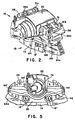
- the disc brake 10 shown in Figures 1-5 is distinguished from disc brakes of the prior art such as disclosed in U.S. Patent 4,200,173 by the relationship between a caliper 16 and an anchor or support member 12 of the present invention.
- the anchor 12 has a base 35 that is fixed to the housing 14 of a vehicle by bolts 15,15' with first 36 and second 38 rails that are spaced apart and extend there from along perpendicular planes such that an ear 29a on backing plate 29 of a first friction member 30 and ear 31 a on backing plate 31 of a second friction member 32 are respectively located on the first rail 36 while ear 29b on backing plate 29 of the first friction member 30 and ear 31 b on backing plate 31 of the second friction member 32 are respectively located on the second rail 38 such that face 30f on the first friction member 30 and face 32f on the second friction member 32 are in respective parallel alignment with face 34a and 34b on rotor 34.
- the caliper 16 is solely supported on the anchor or support member 12 such the spring clip 40 on second friction member 32 is attached to arm 20 that extends from a bridge 22 such that face 32f of the second friction member 32 is radially aligned face 34b of rotor 34.
- face 30f of the first friction member 30 is aligned with face 34a of rotor 34 by being attached to a piston 26 associated with the actuation section 18 of the disc brake 10.
- pressurized fluid is supplied to an actuation section 18 to develop a force for moving the face 30f on first friction member 30 into engagement with face 34a and for moving face 32f on the second friction member 32 into engagement with face 34b of rotor to retard the rotation of rotor 34 and effect a brake application.
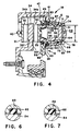
- the anchor 12 further includes a horizontal projection 50 that extends from a flange 49 on base 35 in a direction away opposite from the rails 36 and 38, as best illustrated, in Figure 4 to an end 51.
- the horizontal projection 50 has a bore 52 that extends from face 47 to end 51 that is parallel to the rails 36 and 38.
- Bore 52 has a first diameter 54 adjacent face 47 that is separated from a second diameter 56 adjacent end 51 by a shoulder 58 with a radial groove 59 adjacent face 47 for receiving a first seal 61 and an axial groove 60 located in the first diameter 54 from receiving a square faced seal 62, see Figure 6.
- a piston 64 having a first diameter 66 separated from a second diameter 68 by a shoulder 70 is received in bore 52 such that seal 62 engages the first diameter 66 to define an effective diameter D 1 within bore 52.
- the engagement of piston 64 with bore 52 is such that the piston 64 is located in perpendicular alignment with rotor 34.
- the horizontal projection 50 of anchor 12 is further characterized in that a peripheral surface 67 thereon has a first diameter 69 that is separated from a second diameter 71 by a shoulder 73 such that the second diameter 71 is equal to the first diameter 66 of bore 54.
- the caliper 16 is distinguished in that the actuation section 18 has a housing 74 with bore 76 therein as illustrated in Figure 4 with a first diameter 78 and a second diameter 80 with the first diameter corresponding and concentric with diameter 69 and diameter 80 corresponding concentric with diameter 71 on peripheral surface 67 of the horizontal projection 50.
- An axial groove 82 located in diameter 80 receives a square face seal 84 identical to face seal 62 such that when bore 76 receives end 51 on the horizontal projection 50 an actuation chamber 88 is defined for actuation section 18 and the housing 74 functions as a second piston having an effective diameter D 2 that is equal to the effective area of piston 64.
- the housing 74 has a radial groove 90 adjacent diameter 80 that receives a seal 92 such that surface defined by diameter 80 is protected from the environment.
- the length of the horizontal projection 50 from face 47 to end 51 is such that when caliper housing 74 is positioned thereon as illustrated in Figure 4, the caliper 16 is suspended and held over the rotor 34.
- the housing 74 is held in a horizontal plane and kept from rotating by keys 96, 96' that extend from base 35 being located in slots 94, 94' in housing 74 as illustrated in Figure 5.
- pressurized fluid is presented to actuation chamber 88 that acts on piston 64 to move the first friction member 30 toward rotor 34 and acts on the second piston defined by housing 74 to move caliper 16 away from end 51 of the horizontal projection 50 such that bridge 22 pulls the second friction member 32 toward rotor 34.
- the effective area defined by diameter 66 for piston 64 and the effective area defined by diameter 78 for housing 74 are equal and as a result a same actuation force moves piston 64 and housing 74 to effect a brake application.
Landscapes
- Engineering & Computer Science (AREA)
- General Engineering & Computer Science (AREA)
- Mechanical Engineering (AREA)
- Braking Arrangements (AREA)
Applications Claiming Priority (1)
| Application Number | Priority Date | Filing Date | Title |
|---|---|---|---|
| US10/908,592 US20060260887A1 (en) | 2005-05-18 | 2005-05-18 | Disc Brake |
Publications (2)
| Publication Number | Publication Date |
|---|---|
| EP1724488A2 true EP1724488A2 (de) | 2006-11-22 |
| EP1724488A3 EP1724488A3 (de) | 2008-01-23 |
Family
ID=36859156
Family Applications (1)
| Application Number | Title | Priority Date | Filing Date |
|---|---|---|---|
| EP06010178A Withdrawn EP1724488A3 (de) | 2005-05-18 | 2006-05-17 | Scheibenbremse |
Country Status (2)
| Country | Link |
|---|---|
| US (1) | US20060260887A1 (de) |
| EP (1) | EP1724488A3 (de) |
Citations (2)
| Publication number | Priority date | Publication date | Assignee | Title |
|---|---|---|---|---|
| US4200173A (en) | 1978-08-01 | 1980-04-29 | Kelsey-Hayes Company | Sliding caliper disc brake |
| US6454056B1 (en) | 2001-05-31 | 2002-09-24 | Robert Bosch Corporation | Disc brake with anti-caming and constant bearing length for guide pins |
Family Cites Families (10)
| Publication number | Priority date | Publication date | Assignee | Title |
|---|---|---|---|---|
| US3361229A (en) * | 1966-04-25 | 1968-01-02 | Kelsey Hayes Co | Caliper-type disk brakes |
| US3724606A (en) * | 1970-03-30 | 1973-04-03 | Aisin Seiki | Disk brake assembly |
| JPS5316463B2 (de) * | 1973-02-16 | 1978-06-01 | ||
| JPS5382966A (en) * | 1976-12-29 | 1978-07-21 | Tokico Ltd | Brake cylinder |
| US4220173A (en) * | 1978-07-31 | 1980-09-02 | Brien John W O | Time delay fluid valve |
| DE19601434A1 (de) * | 1996-01-17 | 1997-07-24 | Teves Gmbh Alfred | Scheibenbremse für Kraftfahrzeuge |
| WO1998002338A2 (en) * | 1996-07-12 | 1998-01-22 | Kelsey Hayes Company | Caliper for disc brake assembly |
| US6378664B1 (en) * | 2000-02-28 | 2002-04-30 | Delpi Technologies, Inc. | Consistent retraction device for disc brake calipers |
| US6345701B1 (en) * | 2000-06-28 | 2002-02-12 | Kelsey-Hayes Company | Anchor bracket and brake shoe assembly for use in a disc brake assembly |
| US6719104B1 (en) * | 2001-12-28 | 2004-04-13 | Kelsey-Hayes Company | Composite caliper for a disc brake assembly and method for producing same |
-
2005
- 2005-05-18 US US10/908,592 patent/US20060260887A1/en not_active Abandoned
-
2006
- 2006-05-17 EP EP06010178A patent/EP1724488A3/de not_active Withdrawn
Patent Citations (2)
| Publication number | Priority date | Publication date | Assignee | Title |
|---|---|---|---|---|
| US4200173A (en) | 1978-08-01 | 1980-04-29 | Kelsey-Hayes Company | Sliding caliper disc brake |
| US6454056B1 (en) | 2001-05-31 | 2002-09-24 | Robert Bosch Corporation | Disc brake with anti-caming and constant bearing length for guide pins |
Also Published As
| Publication number | Publication date |
|---|---|
| US20060260887A1 (en) | 2006-11-23 |
| EP1724488A3 (de) | 2008-01-23 |
Similar Documents
| Publication | Publication Date | Title |
|---|---|---|
| US6386335B1 (en) | Anchor bracket and brake shoe assembly for use in a disc brake assembly | |
| CN113195923B (zh) | 用于制动卡钳的衬垫-弹簧组件 | |
| US5947234A (en) | Disc brake | |
| US6298953B1 (en) | Disc brake | |
| US7201258B2 (en) | Disc brake | |
| US6257378B1 (en) | Caliper for disc brake assembly | |
| WO2002099303A1 (en) | Floating caliper brake guide pin arrangement | |
| US7337881B1 (en) | Full float multi-force caliper assembly | |
| US12234871B2 (en) | Brake pad retainer system, brake pad, and vehicle | |
| EP1724488A2 (de) | Scheibenbremse | |
| CN110892170B (zh) | 制动卡钳与至少一个衬垫的组件 | |
| EP1963701B1 (de) | Scheibenbremsensattel | |
| WO2009070198A2 (en) | A disc brake | |
| CA1177001A (en) | Disc brake anti-rattle device | |
| JPS6049778B2 (ja) | 摺動キヤリパ式デイスクブレーキ | |
| JP5879032B2 (ja) | ディスクブレーキ | |
| US20070068747A1 (en) | Self-energizing sliding caliper | |
| EP1350038B1 (de) | Montage von reibungselementen an scheibenbremsen | |
| US6926124B2 (en) | Floating disk brake | |
| GB2291150A (en) | Disc brake | |
| CA1088002A (en) | Torque bars for sliding caliper disc brake | |
| JP3792877B2 (ja) | ディスクブレーキ装置 | |
| EP1346165B1 (de) | Stütz- und führungsanordnung für reibelemente in scheibenbremsen | |
| JPH075302Y2 (ja) | 車両用ディスクブレーキの摩擦パッド戻し構造 | |
| US20020088675A1 (en) | Disc brake |
Legal Events
| Date | Code | Title | Description |
|---|---|---|---|
| PUAI | Public reference made under article 153(3) epc to a published international application that has entered the european phase |
Free format text: ORIGINAL CODE: 0009012 |
|
| AK | Designated contracting states |
Kind code of ref document: A2 Designated state(s): AT BE BG CH CY CZ DE DK EE ES FI FR GB GR HU IE IS IT LI LT LU LV MC NL PL PT RO SE SI SK TR |
|
| AX | Request for extension of the european patent |
Extension state: AL BA HR MK YU |
|
| PUAL | Search report despatched |
Free format text: ORIGINAL CODE: 0009013 |
|
| AK | Designated contracting states |
Kind code of ref document: A3 Designated state(s): AT BE BG CH CY CZ DE DK EE ES FI FR GB GR HU IE IS IT LI LT LU LV MC NL PL PT RO SE SI SK TR |
|
| AX | Request for extension of the european patent |
Extension state: AL BA HR MK YU |
|
| RIC1 | Information provided on ipc code assigned before grant |
Ipc: F16D 65/00 20060101ALI20071219BHEP Ipc: F16D 55/226 20060101ALI20071219BHEP Ipc: F16D 55/224 20060101AFI20060926BHEP |
|
| AKX | Designation fees paid | ||
| STAA | Information on the status of an ep patent application or granted ep patent |
Free format text: STATUS: THE APPLICATION IS DEEMED TO BE WITHDRAWN |
|
| 18D | Application deemed to be withdrawn |
Effective date: 20080724 |
|
| REG | Reference to a national code |
Ref country code: DE Ref legal event code: 8566 |