EP1723482B1 - Power system - Google Patents
Power system Download PDFInfo
- Publication number
- EP1723482B1 EP1723482B1 EP05711053A EP05711053A EP1723482B1 EP 1723482 B1 EP1723482 B1 EP 1723482B1 EP 05711053 A EP05711053 A EP 05711053A EP 05711053 A EP05711053 A EP 05711053A EP 1723482 B1 EP1723482 B1 EP 1723482B1
- Authority
- EP
- European Patent Office
- Prior art keywords
- power
- line
- voltage
- impedance
- load
- Prior art date
- Legal status (The legal status is an assumption and is not a legal conclusion. Google has not performed a legal analysis and makes no representation as to the accuracy of the status listed.)
- Expired - Lifetime
Links
- 238000000034 method Methods 0.000 claims abstract description 21
- 230000005540 biological transmission Effects 0.000 claims abstract description 10
- 230000006641 stabilisation Effects 0.000 claims abstract description 4
- 238000011105 stabilization Methods 0.000 claims abstract description 4
- 238000012546 transfer Methods 0.000 claims description 8
- 238000004088 simulation Methods 0.000 description 7
- 230000006870 function Effects 0.000 description 5
- 230000001419 dependent effect Effects 0.000 description 3
- 230000033228 biological regulation Effects 0.000 description 2
- 238000013178 mathematical model Methods 0.000 description 2
- 238000013139 quantization Methods 0.000 description 2
- 238000005070 sampling Methods 0.000 description 2
- 230000003068 static effect Effects 0.000 description 2
- 230000001052 transient effect Effects 0.000 description 2
- 238000004804 winding Methods 0.000 description 2
- 230000003416 augmentation Effects 0.000 description 1
- 239000003990 capacitor Substances 0.000 description 1
- 230000008859 change Effects 0.000 description 1
- 244000145845 chattering Species 0.000 description 1
- 230000001143 conditioned effect Effects 0.000 description 1
- 238000011217 control strategy Methods 0.000 description 1
- 230000003247 decreasing effect Effects 0.000 description 1
- 238000013461 design Methods 0.000 description 1
- 238000010586 diagram Methods 0.000 description 1
- 238000005183 dynamical system Methods 0.000 description 1
- 230000000694 effects Effects 0.000 description 1
- 238000001914 filtration Methods 0.000 description 1
- 230000003993 interaction Effects 0.000 description 1
- 230000007774 longterm Effects 0.000 description 1
- 230000000087 stabilizing effect Effects 0.000 description 1
Images





Classifications
-
- G—PHYSICS
- G05—CONTROLLING; REGULATING
- G05F—SYSTEMS FOR REGULATING ELECTRIC OR MAGNETIC VARIABLES
- G05F1/00—Automatic systems in which deviations of an electric quantity from one or more predetermined values are detected at the output of the system and fed back to a device within the system to restore the detected quantity to its predetermined value or values, i.e. retroactive systems
- G05F1/10—Regulating voltage or current
- G05F1/12—Regulating voltage or current wherein the variable actually regulated by the final control device is AC
- G05F1/14—Regulating voltage or current wherein the variable actually regulated by the final control device is AC using tap transformers or tap changing inductors as final control devices
Definitions
- the present invention relates to a power system and in particular to a method for voltage stabilization of an electrical power network system comprising a producing power network system side and a consuming power network side to maintain voltage.
- a power system consists of several electrical components (e.g. generators, transmission lines, loads) connected together, its purpose being generation, transfer and usage of electrical power.
- OLTC On-Line Tap Changer
- Voltage stability of a power system is defined by the IEEE Power System Engineering Committee as being the ability of the system to maintain voltage such that when load admittance is increased, load power will increase so that both power and voltage are controllable [2].
- Voltage stability in power networks is a widely studied problem. Several voltage collapses resulting in system-wide black-outs made this problem of major concern in the power system community.
- the actions taken by the power companies is usually one or both of the following:
- a three-phase four-wire power conditioner with load-dependent voltage regulation for energy saving is presented.
- the power conditioner employs the rectifier-inverter topology and combines active power filtering with load voltage regulation for energy saving purposes.
- This invention is concerned with dynamic stability of a power systems.
- the inventors propose a dynamic feedback and feed-forward based compensation that aims at stabilization of the power grid.
- This control structure is intended to function as an emergency control scheme, i.e., it will be active in critical situations when the network is near voltage collapse.
- the considered power system is shown in Figure 1 . It is a radial system containing a generator E s , a transmission line with impedance Z ⁇ ln , a transformer with an on-line tap changer (OLTC) and a load with impedance Z ⁇ LD .
- the on-line tap changer regulates the voltage on the load side at a desired value V ref .
- the load itself dynamically changes its impedance. Most of the loads are such that they try to absorb a certain amount of power. That implies that when the load voltage drops, the loads will decrease their impedance to keep power constant.
- the invention according to claim 1 proposes a method that momentarily changes the behavior of the OLTC when the line impedance changes such that the system is driven into the critical operation regime.
- changes of the load impedance is taken into account.
- the proposed control structure is meant to operate in case of dynamic instabilities. This means that after a line and/or load impedance change (for example due to a line failure or an increase of power request from the load) the power grid is still statically capable of transferring the load power request.
- the present invention makes use of a mathematical model:
- the present mathematical model is able to capture two instability scenarios.
- the methods described in the present application adds stability margins so that the risk of the second scenario is significantly reduced.
- the stabilizing property of the methods will also help restoring stability after an overload condition when load shedding has been applied.
- FIG. 7 A block diagram over the structure of the proposed compensator is shown in Figure 7 .
- the compensator consists of two susbsystems.
- the first susbsystems consists of a feed-forward compensator and the second consists of a feedback controller.
- the goal of the feed-forward compensation is to improve the convergence ratio of the system in case of a fault in the transmission line.
- the compensator will drive the system to the stable equilibrium point in case of a line fault.
- this method works only if, after the fault the system is still the stable region (i.e. n 2 Y LD Z In ⁇ 1).
- This compensating subsystem aims to prevent the grid from entering an unstable operating regime. For this it uses information about the line impedance.
- the second control subsystem aims to drive the grid from the unstable operation regime to the stable operation regime. For this it uses information about the line impedance, load impedance, and transformer ratio.
- the chosen quantization step q is 0.027.
- the chosen sampling time is 30 seconds, which approximates the mechanical delay of the tap-changer and the OLTC delay timer.
- the three-stage control system consists of the following compensator:
- V ff is conditioned by V fb .
- Q ref 0.16.
- the first 800 seconds in the simulations represent the initial transient to the studied equilibrium point and it has no physical interpretation.
- V ff shows a significant increase.
- the new equilibrium point is not achieved the system ends up in the unstable operating region (at around 1100 seconds). This will trigger the second stage of the controller, decreasing V fb . This will result in a decrease of the overall voltage reference value such that the system is brought back in the stable region.
- the third control stage load shedding
- V ff the first step
- the delay timer is inverse proportional to the control error
Landscapes
- Engineering & Computer Science (AREA)
- Power Engineering (AREA)
- Physics & Mathematics (AREA)
- Electromagnetism (AREA)
- General Physics & Mathematics (AREA)
- Radar, Positioning & Navigation (AREA)
- Automation & Control Theory (AREA)
- Supply And Distribution Of Alternating Current (AREA)
- Control Of Electrical Variables (AREA)
- Control Of Eletrric Generators (AREA)
Abstract
Description
- The present invention relates to a power system and in particular to a method for voltage stabilization of an electrical power network system comprising a producing power network system side and a consuming power network side to maintain voltage.
- A power system consists of several electrical components (e.g. generators, transmission lines, loads) connected together, its purpose being generation, transfer and usage of electrical power.
- In a conventional On-Line Tap Changer (OLTC) the control is given by a simple integrator with a time delay and deadband. The size of the deadband sets the tolerance for long term voltage deviation. The reference signal for the integrator is the secondary voltage setpoint. This is usually kept constant at the desired secondary voltage.
- Voltage stability of a power system is defined by the IEEE Power System Engineering Committee as being the ability of the system to maintain voltage such that when load admittance is increased, load power will increase so that both power and voltage are controllable [2].
- Voltage stability in power networks is a widely studied problem. Several voltage collapses resulting in system-wide black-outs made this problem of major concern in the power system community.
- In todays state-of-the-art practice, the following methods are used to detect that the system is close to voltage instability:
- 1. As too much power is requested by the load, the generators will start using their rotational energy, implying that the frequency of the voltage (50/60 Hz) will start to decrease. Detecting a low frequency has been a too slow measure to stop the voltage collapse in for example eastern USA in 2003.
- 2. Another sign of overload is that the load voltage drops. However, it has been shown that neither this is a good measure for the instability of the grid.
- Using any of the above methods (or similar), the actions taken by the power companies is usually one or both of the following:
- 1. Connect capacitor banks, to increase the active effect that can be consumed by the load. If this is done in time, a voltage collapse can sometimes be avoided. A disadvantage of this method is that it makes the network more sensible to ioad variations.
- 2. Disconnect certain amounts of load (load shedding). This is a very "expensive" measure, and therefore avoided for as long as possible by the power company. However this measure can prevent the whole power net from collapsing.
- In
US 6,313,614 to Persson et al. a method is presented to control the secondary voltage in a transformer device connected to a power network, the transformer comprising a tap-changer which, in dependence on a supplied control signal influences the voltage ratio of the transformer device. The control signal is dependent on the deviation between a control quantity and a given reference value therefore, wherein the control quantity is dependent on the voltage and frequency of the secondary voltage mentioned above. - In [7] the voltage instability phenomena in power systems is described and how it can be analyzed and prevented.
- In [8] a three-phase four-wire power conditioner with load-dependent voltage regulation for energy saving is presented. The power conditioner employs the rectifier-inverter topology and combines active power filtering with load voltage regulation for energy saving purposes.
- In [9] it is discussed how the maximum power transfer limit can be affected by operation of on-load tap changers.
- In [10] the voltage instability problem from a hybrid system view is presented.
- This invention is concerned with dynamic stability of a power systems. The inventors propose a dynamic feedback and feed-forward based compensation that aims at stabilization of the power grid. This control structure is intended to function as an emergency control scheme, i.e., it will be active in critical situations when the network is near voltage collapse.
- The considered power system is shown in
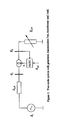
Figure 1 . It is a radial system containing a generator Es , a transmission line with impedance Z̃ln, a transformer with an on-line tap changer (OLTC) and a load with impedance Z̃ LD . The on-line tap changer regulates the voltage on the load side at a desired value Vref. The load itself dynamically changes its impedance. Most of the loads are such that they try to absorb a certain amount of power. That implies that when the load voltage drops, the loads will decrease their impedance to keep power constant. - There are two control loops in this system, acting independently of each other.
- The On-Line Tap Changer (OLTC) in the transformer, which tries to keep the voltage on the load side constant at the reference value Vref.
- The load itself can be viewed as a control system, which changes its impedance (or equally admittance) in order to absorb a given power.
- The problem is that these two independent control loops can, due to their non-linear interaction, drive the system to voltage instability even if the system could handle the power required by the load.
- The invention according to
claim 1 proposes a method that momentarily changes the behavior of the OLTC when the line impedance changes such that the system is driven into the critical operation regime. In an embodiment of the invention changes of the load impedance is taken into account. - It is important to again point out that the proposed control structure is meant to operate in case of dynamic instabilities. This means that after a line and/or load impedance change (for example due to a line failure or an increase of power request from the load) the power grid is still statically capable of transferring the load power request.
- In particular the method of the invention is characterized in that the power transfer YLD, wherein YLD is power load admittance, is dynamically maintained below the loci for maximum power transfer, n2YLDZLN = 1, wherein YLD is power load admittance, ZLN is transmission line impedance and n is transformer ratio, preferably YLD is maintained at a stable equilibrium.
- The present invention makes use of a mathematical model:
- For ease of reference a list of used variables is compiled below:
- · Z̃ LD = Z LDe jΦ - load impedance,
- · Ỹ LD =1/Z̃ LD - load admittance,
- · Z̃ LN = ZLN e jΘ- transmission line impedance,
- · Ẽ s = Ese j0 - generator voltage,
- · Ṽ 1 - voltage on the primary side of the transformer,
- · Ṽ 2-voltage on the secondary side of the transformer,
- · n - transformator ratio,
- · Vref - reference voltage,
- · Ĩ 1 - current in the primary winding of the transformer,
- · Ĩ 2- current in the secondary winding of the transformer
- For the system in
Figure 1 , some basic relations can be stated [4]:


- The function is a nonlinear function that determines the typical dependence of the active power on the line and load impedance (
Figure 2 ). Initially, for increasing YLD, the active power will increase. However, after a certain load admittance the transfered active power starts to decrease. For ZLD /n 2 = ZIn a maximum active power will be transmitted through the line. - Then for a constant active power load, a suitable model is:

while the OLTC can be approximated by an integrator:
- In order to understand the behavior of the proposed model, consider first the dynamical system in equation (1). Due to the built-in non-linearity, the system can have two equilibrium points corresponding the reference active power (see
Figure 2 ). It can be shown that the one to the left of the peak is stable while the other is unstable. This will determine the typical behavior of a power system. After achieving the maximum value of the transfered active power, if the load admittance continues to increase, the system enters the unstable region. This will lead to instability if the load admittance achieves the value corresponding to the unstable equilibrium point. - Simulation results for the above model are shown in
Figure 3 . The variable in the plot are the maximum transferable active power, the transfered active power and load admittance. In this scenario the load is trying to absorb an active power of 0.7 (dashed line). The initial value for the line impedance is 1. At t=75 a fault is simulated in the line by changing its impedance to 1.5. As shown in the first sub-plot, this implies that the maximum power that can be transferred through the line will drop just below 0.7. The load tries to absorb the desired active power by reducing its impedance (see the second and third sub-plot). However since that power is not achievable, the system will end up in instability and voltage collapse. - Considering both equations (1) and (2) in the model, similar qualitative behavior is retain as for the scalar case.
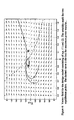
Figure 4 shows the vector field near the equilibrium points (marked with asterisks). The dashed line is given by the curve n 2 YLDZ ln =1, i.e. the loci of maximum power transfer (this happens if the line impedance and the load impedance are equal). Notice the unstable behavior to the right of this curve. - The present mathematical model is able to capture two instability scenarios.
- 1. The first case is shown in
Figure 3 , where due to some fault in the transmission line the system is no longer able to transfer the requested active power. This corresponds to the situation when the system has no real equilibrium points. This is the classical case, which can be analyzed even with static methods. - 2. Another instability scenario is when a stable equilibrium point exists, but where the system ends up in instability due to some transients. In
Figure 6 , at 50 time units, a fault in the transmission line is simulated by a step increase of the line impedance. This step is such that a stable equilibrium point still exists, that is, the network should be able to transfer the requested active power. However, due to the fact that the operating point is close to the maximum transferable active power, an overshoot in Yn2, will drive the system in the unstable region and the voltage will collapse. - The methods described in the present application adds stability margins so that the risk of the second scenario is significantly reduced. The stabilizing property of the methods will also help restoring stability after an overload condition when load shedding has been applied.
- The proposed methods comes in before the
methods - As can be seen in
Figure 4 , it is desirable to move the system away from the unstable region above the stability limit (dashed curve). Since the load dynamics cannot be changed (except by load shedding), we suggest to momentarily alter the transformer ratio n so as to avoid the unstable region. - The following sections describe how this can be done in practice, indirectly, by changing the voltage reference Vref given to the standard OLTC.
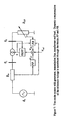
- A block diagram over the structure of the proposed compensator is shown in
Figure 7 . - The compensator consists of two susbsystems. The first susbsystems consists of a feed-forward compensator and the second consists of a feedback controller.
The goal of the feed-forward compensation is to improve the convergence ratio of the system in case of a fault in the transmission line. In other words, the compensator will drive the system to the stable equilibrium point in case of a line fault. However, this method works only if, after the fault the system is still the stable region (i.e. n 2 YLDZ In < 1). - The idea of using such compensation is suggested by the structure of the presented simplified model. It is rather straightforward to show that the line impedance Z ln acts as a load disturbance on the system, similarly to Pref. In addition, the line impedance can be considered measurable. It is natural then to use a feed-forward compensation from the line impedance in order to diminish the influence of line faults. If the transformer ratio n would be directly accessible for control purposes, the transient influence of line fault could be (at least theoretically) completely removed. Although only Vref is accessible, it is still possible to considerably improve the line-fault behavior of the system.
- This compensating subsystem aims to prevent the grid from entering an unstable operating regime. For this it uses information about the line impedance.
- A suitable feedforward compensation is given by the first order filter

where T, Td are tuning parameters. - In case the system enters the unstable region (i.e. n 2 YLDZ ln > 1), another control strategy has to be applied, which is described in the next section.
- When the system is in the unstable region, it is desirable to drive it back to the stable operation regime. This can be done by reducing the reference voltage as long as the system is in the unstable region. Such a compensation can be achieved by a static nonlinear feedback. In
Figure 4 , as a result of the compensation, the vector field above the line n 2 YLDZ ln = 1 will point inwards (seeFigure 5 ). It can be seen in the the plots that the region of attraction for the stable equilibrium point has been considerably increased. - It is to be mentioned here that the idea of using the distance from the peak of the function f, corresponding to equation (1) (see
Figure 2 ) in voltage stability studies has been recently proposed in [3]. However, it has never been used (to the best of the authors knowledge) for dynamic compensation of the voltage reference signal. - Thus the second control subsystem aims to drive the grid from the unstable operation regime to the stable operation regime. For this it uses information about the line impedance, load impedance, and transformer ratio.
- A suitable feedback controller is:

where α is a tuning parameter that is influencing the region of atraction of the equilibrium point. - In order to obtain more realistic simulation results the initial design model has been modified as follows:
- the dynamics have been scaled according to the benchmark model [5],
- additional dynamics have been introduced for the load argument, ϕ,
- load shedding input k has been added,
- saturation and quantization is introduced on the transformer ration n. The latter is intended to simulate the mechanical tap-changer,
- since the tap-changer is inherently a discrete system, a discrete time representation of the OLTC dynamics is used. Notice that the tap-changer can make only one step at the time.
- in order to avoid chattering, an OLTC system usually contains a dead-zone on the control error.
- The saturation on n has the limits n min=0.75,n max=1.25, and the dead-zone has the limits ±0.03. The chosen quantization step q is 0.027. The chosen sampling time is 30 seconds, which approximates the mechanical delay of the tap-changer and the OLTC delay timer.
- The three-stage control system consists of the following compensator:
- feed-forward compensation:

- feedback compensation:
Vfb = -max(0,α(n 2 YLD /1/Z ln)). The parameter a influences the region of attraction of the equilibrium point. In the simulations α=1.1. - The first two control signals ( and ) augment the reference value as follows:

where dzn is the dead-zone function. - However, a more complex augmentation is also possible, e.g. Vff is conditioned by Vfb.
- In the simulations, the following parameters have been used: Vref =1.1, Pref = 0.78, Es =1.5, T=60, and θ=1.47 radians. In addition, in the first simulation scenario (
Figure 8 ) the reference reactive power is Qref = 0.16. The scenario consists of a line tripping at t=800 seconds, when the line impedance Z ln is increased from 1 to 1.2. The first 800 seconds in the simulations represent the initial transient to the studied equilibrium point and it has no physical interpretation. At the moment of the fault, Vff shows a significant increase. However, since the new equilibrium point is not achieved the system ends up in the unstable operating region (at around 1100 seconds). This will trigger the second stage of the controller, decreasing Vfb . This will result in a decrease of the overall voltage reference value such that the system is brought back in the stable region. Notice that throughout the entire control sequence, the third control stage (load shedding) is not engaged, i.e. k=0. - It is important to remark that the first step (i.e. Vff ) is sensitive to the fault timing due to the low sampling frequency. Similarly if multiple steps (e.g. two) would be possible, the performance would increase significantly. Nevertheless, even in the case of the state-of-the-art OLTCs, where the delay timer is inverse proportional to the control error, considerable improvements can be obtained in compensating for line tripping.
-
- [1] Miroslav Begovic and Damir Novosel. A novel method for voltage instability protection. In Proceedings of the 35th Hawaii Internation Conference on System Sciences, 2002.
- [2] Miroslav Begovic, Damir Novosel, and Mile Milisavljevic. Trends in power system protection and control. In .
- [3] D.E. Julian, R.P. Schulz, K.T. Vu, W.H. Quaintance, N.B. Bhatt, and D. Novosel. Quantifying proximity to voltage collapse using the voltage instability predictor (vip). In Power Engineering Society Summer Meeting, IEEE, 2000.
- [4] Prabha Kundur. Power System Stability and Control. McGraw-Hill, Inc., 1993.
- [5] Mats Larsson. A simple test system illustrating load-voltage dynamics in power sytems. In http://www.dii.unisi.it/hybrid/cc/ .
- [6] Khoi Tien Vu and Damir Novosel. Voltage instability predictor (VIP) - method and system for performing adaptive control to improve voltage stability in power systems. In United States Patent Nr.
US 6,219,591 B1, 2001 . - [7] Thierry van Cutsem. Voltage Instability: Phenomena, Countermeasures, and Analysis Methods. In Proceedings of the IEEE, vol. 88, no. 2, February 2000; pp.208-227.
- [8] S.J. Chiang. A three-phase Four-wire Power conditioner With Load-Dependent Voltage Regulation For Energy Saving. In 18th Annual IEEE Applied Power Conference and Exposition (APEC 2003), February 9-13, 2003; pp. 159-164.
- [9] T.X. Thu et al., An Investigation into the OLTC Effects on Voltage Collapse. In IEEE Transactions on Power Systems, vol. 15, no. 2, May 2000; pp. 515-521.
- [10]Q.Y. Tong et al., Hybrid system View of Voltage Instability Problem. In Proceedings of the Second International Conference on Machine Learning and Cybernetics, Xian, 2-5 November 2003; pp. 915-918.


Claims (4)
- Method for voltage stabilization of an electrical power network system, the electrical power network system comprising a producing power network system side, a consuming power network side comprising a power load, a power transmission line with impedance ZLN , a transformer and an on-line tap changer (OLTC) added to the transformer,
the method characterised by,
in case of dynamic instabilities measuring the line impedance and controlling a transformer ratio (n) by changing a voltage reference (Vref) of the on-line tap changer, where the voltage reference is changed according to a feed forward compensation from the line impedance. - Method according to claim 1, characterised in that
the feed forward compensation drives the power network system to a stable equilibrium point in a stable region where the stable region lies below the loci for maximum power transfer, n 2 YLDZLN =1, wherein YLD is power load admittance, ZLN is transmission line impedance and n is transformer ratio. - Method according to claim 1 or 2, characterised in that
the feed forward compensation is provided by a first order filter Hff (s) = sTd /(sT + 1) , wherein T and Td are tuning parameters. - Method according to any of claims 1 to 3, characterised in that
a feedback controller (FB) is provided according to the equation
Vfb = -max(0,a(n 2 YLD -1/ZLN ), wherein a is a tuning parameter that is influencing the region of attraction of the equilibrium point.
Applications Claiming Priority (2)
| Application Number | Priority Date | Filing Date | Title |
|---|---|---|---|
| SE0400301A SE0400301D0 (en) | 2004-02-11 | 2004-02-11 | Power system |
| PCT/SE2005/000192 WO2005078546A1 (en) | 2004-02-11 | 2005-02-11 | Power system |
Publications (2)
| Publication Number | Publication Date |
|---|---|
| EP1723482A1 EP1723482A1 (en) | 2006-11-22 |
| EP1723482B1 true EP1723482B1 (en) | 2008-04-09 |
Family
ID=31885297
Family Applications (1)
| Application Number | Title | Priority Date | Filing Date |
|---|---|---|---|
| EP05711053A Expired - Lifetime EP1723482B1 (en) | 2004-02-11 | 2005-02-11 | Power system |
Country Status (7)
| Country | Link |
|---|---|
| US (1) | US7982442B2 (en) |
| EP (1) | EP1723482B1 (en) |
| CN (1) | CN1954280A (en) |
| AT (1) | ATE391950T1 (en) |
| DE (1) | DE602005005965T2 (en) |
| SE (1) | SE0400301D0 (en) |
| WO (1) | WO2005078546A1 (en) |
Cited By (1)
| Publication number | Priority date | Publication date | Assignee | Title |
|---|---|---|---|---|
| WO2010119136A1 (en) | 2009-04-16 | 2010-10-21 | Kuehn Walter | Method and apparatus for automatic network stabilization in electric power supply systems using at least one converter |
Families Citing this family (11)
| Publication number | Priority date | Publication date | Assignee | Title |
|---|---|---|---|---|
| NO319363B1 (en) | 2002-12-12 | 2005-07-18 | Magtech As | Voltage stabilization system for power supply lines |
| EP2140533A2 (en) * | 2007-03-28 | 2010-01-06 | ABB Research LTD | Damping multiple modes of electromagnetic oscillations in power distribution systems |
| GB0712749D0 (en) * | 2007-07-02 | 2007-08-08 | Areva T & D Uk Ltd | Method of determining voltage stability margin for load shedding within an electrical power system |
| US7884592B2 (en) * | 2009-01-26 | 2011-02-08 | The United States Of America As Represented By The Secretary Of The Navy | Energy efficient method for changing the voltage of a DC source to another voltage in order to supply a load that requires a different voltage |
| WO2011060811A1 (en) * | 2009-11-17 | 2011-05-26 | Areva T&D Uk Limited | Method of adjusting a voltage across terminals of a load |
| US9400512B2 (en) * | 2013-12-17 | 2016-07-26 | General Electric Company | System and method for operating an on load tap changer for regulating voltage on an electric power system |
| WO2016067438A1 (en) * | 2014-10-31 | 2016-05-06 | 株式会社日立製作所 | System stabilizing control device and method |
| US10048709B2 (en) | 2016-09-19 | 2018-08-14 | General Electric Company | System and method for regulation of voltage on an electric power system |
| US11063435B2 (en) | 2017-08-07 | 2021-07-13 | Raytheon Company | Energy-based adaptive stability control system |
| WO2019114936A1 (en) * | 2017-12-12 | 2019-06-20 | Telefonaktiebolaget Lm Ericsson (Publ) | Improved latency management |
| US11349292B2 (en) | 2019-04-09 | 2022-05-31 | Raytheon Company | Arc flash protection of power systems |
Family Cites Families (9)
| Publication number | Priority date | Publication date | Assignee | Title |
|---|---|---|---|---|
| US2753512A (en) * | 1954-02-23 | 1956-07-03 | Sorensen & Company Inc | Voltage regulator |
| NL144070B (en) * | 1964-06-27 | 1974-11-15 | Philips Nv | DC VOLTAGE SOURCE WITH REDUCED DYNAMIC OUTPUT IMPEDANCE. |
| US3507096A (en) * | 1967-03-07 | 1970-04-21 | Cottrell Res Inc | Method and apparatus for automatic voltage control of electrostatic precipitators |
| US4434388A (en) * | 1981-09-03 | 1984-02-28 | Carver Leroy J | Electrical lighting controller |
| US4560917A (en) * | 1983-12-21 | 1985-12-24 | Westinghouse Electric Corp. | Static VAR generator having reduced harmonics |
| SE503374C2 (en) * | 1994-11-15 | 1996-06-03 | Asea Brown Boveri | Method and apparatus for controlling a series compensated rectifier station included in a system for transmitting high voltage direct current |
| SE511265C2 (en) * | 1998-01-21 | 1999-09-06 | Abb Ab | Method and apparatus for controlling a secondary voltage of a winding switch transformer device |
| US6219591B1 (en) * | 1998-05-15 | 2001-04-17 | Abb Power T&D Company Inc. | Voltage instability predictor (VIP)—method and system for performing adaptive control to improve voltage stability in power systems |
| US20060022648A1 (en) * | 2004-08-02 | 2006-02-02 | Green Power Technologies Ltd. | Method and control circuitry for improved-performance switch-mode converters |
-
2004
- 2004-02-11 SE SE0400301A patent/SE0400301D0/en unknown
-
2005
- 2005-02-11 CN CNA2005800045302A patent/CN1954280A/en active Pending
- 2005-02-11 US US10/589,197 patent/US7982442B2/en not_active Expired - Fee Related
- 2005-02-11 DE DE602005005965T patent/DE602005005965T2/en not_active Expired - Lifetime
- 2005-02-11 AT AT05711053T patent/ATE391950T1/en not_active IP Right Cessation
- 2005-02-11 WO PCT/SE2005/000192 patent/WO2005078546A1/en not_active Ceased
- 2005-02-11 EP EP05711053A patent/EP1723482B1/en not_active Expired - Lifetime
Cited By (1)
| Publication number | Priority date | Publication date | Assignee | Title |
|---|---|---|---|---|
| WO2010119136A1 (en) | 2009-04-16 | 2010-10-21 | Kuehn Walter | Method and apparatus for automatic network stabilization in electric power supply systems using at least one converter |
Also Published As
| Publication number | Publication date |
|---|---|
| EP1723482A1 (en) | 2006-11-22 |
| SE0400301D0 (en) | 2004-02-11 |
| WO2005078546A1 (en) | 2005-08-25 |
| US7982442B2 (en) | 2011-07-19 |
| CN1954280A (en) | 2007-04-25 |
| ATE391950T1 (en) | 2008-04-15 |
| DE602005005965T2 (en) | 2009-07-02 |
| DE602005005965D1 (en) | 2008-05-21 |
| US20080122414A1 (en) | 2008-05-29 |
Similar Documents
| Publication | Publication Date | Title |
|---|---|---|
| Tambey et al. | Damping of power system oscillations with unified power flow controller (UPFC) | |
| Arnborg et al. | On influence of load modelling for undervoltage load shedding studies | |
| Kocaarslan et al. | Fuzzy logic controller in interconnected electrical power systems for load-frequency control | |
| Çam et al. | A fuzzy gain scheduling PI controller application for an interconnected electrical power system | |
| US7982442B2 (en) | Power system | |
| Wang | Interactions and multivariable design of multiple control functions of a unified power flow controller | |
| Vu et al. | Voltage instability: mechanisms and control strategies [power systems] | |
| Wang et al. | A nonlinear controller design for SVC to improve power system voltage stability | |
| JP5367252B2 (en) | AC voltage control method | |
| JP3955758B2 (en) | Reactive power compensator | |
| US4686447A (en) | Static var compensators | |
| Raza et al. | Adaptive drooping control scheme for VSC-MTDC system with multiple renewable energy sites based on variable droop constant | |
| Russo et al. | Robust decentralized PI controllers design for voltage regulation in distribution networks with DG | |
| Ramakrishnan | Delay-dependent stability of networked generator-excitation control systems: An LMI based approach | |
| Devotta et al. | Application of superconducting magnetic energy storage unit in multi-machine power systems | |
| Sabzevari et al. | A novel partial transient active-reactive power coupling method for reactive power sharing | |
| JP4908192B2 (en) | Reactive power compensation apparatus and method | |
| Nanba et al. | Studies on VIPI based control methods for improving voltage stability | |
| Dizdarevic et al. | Possible alleviation of voltage stability problem by use of Unified Power Flow Controller | |
| ELGebaly et al. | Control algorithms of discrete reactive power compensators with pi and fuzzy logic controllers | |
| JPS61156320A (en) | Static reactive power compensator | |
| Gianto | Application of SVC for Electromechanical Oscillation Damping Improvement in Multi-Machine Power System | |
| Chowdhury et al. | An expert system as a system operator's aid in real-time solutions of the optimal power flow | |
| El-Sadek et al. | Combined use of tap-changing transformer and static VAR compensator for enhancement of steady-state voltage stabilities | |
| Fan et al. | Strategy design and transient analysis of ITER PPEN transformer on-load tap changer during converter operation |
Legal Events
| Date | Code | Title | Description |
|---|---|---|---|
| PUAI | Public reference made under article 153(3) epc to a published international application that has entered the european phase |
Free format text: ORIGINAL CODE: 0009012 |
|
| 17P | Request for examination filed |
Effective date: 20060620 |
|
| AK | Designated contracting states |
Kind code of ref document: A1 Designated state(s): AT BE BG CH CY CZ DE DK EE ES FI FR GB GR HU IE IS IT LI LT LU MC NL PL PT RO SE SI SK TR |
|
| 17Q | First examination report despatched |
Effective date: 20070410 |
|
| DAX | Request for extension of the european patent (deleted) | ||
| RIN1 | Information on inventor provided before grant (corrected) |
Inventor name: RANTZER, ANDERS Inventor name: LINCOLN, BO Inventor name: SOLYOM, STEFAN |
|
| RIN1 | Information on inventor provided before grant (corrected) |
Inventor name: RANTZER, ANDERS Inventor name: LINCOLN, BO Inventor name: SOLYOM, STEFAN |
|
| GRAP | Despatch of communication of intention to grant a patent |
Free format text: ORIGINAL CODE: EPIDOSNIGR1 |
|
| GRAS | Grant fee paid |
Free format text: ORIGINAL CODE: EPIDOSNIGR3 |
|
| GRAA | (expected) grant |
Free format text: ORIGINAL CODE: 0009210 |
|
| AK | Designated contracting states |
Kind code of ref document: B1 Designated state(s): AT BE BG CH CY CZ DE DK EE ES FI FR GB GR HU IE IS IT LI LT LU MC NL PL PT RO SE SI SK TR |
|
| REG | Reference to a national code |
Ref country code: GB Ref legal event code: FG4D |
|
| REG | Reference to a national code |
Ref country code: CH Ref legal event code: EP |
|
| REG | Reference to a national code |
Ref country code: IE Ref legal event code: FG4D |
|
| REF | Corresponds to: |
Ref document number: 602005005965 Country of ref document: DE Date of ref document: 20080521 Kind code of ref document: P |
|
| REG | Reference to a national code |
Ref country code: SE Ref legal event code: TRGR |
|
| PG25 | Lapsed in a contracting state [announced via postgrant information from national office to epo] |
Ref country code: SI Free format text: LAPSE BECAUSE OF FAILURE TO SUBMIT A TRANSLATION OF THE DESCRIPTION OR TO PAY THE FEE WITHIN THE PRESCRIBED TIME-LIMIT Effective date: 20080409 |
|
| NLV1 | Nl: lapsed or annulled due to failure to fulfill the requirements of art. 29p and 29m of the patents act | ||
| ET | Fr: translation filed | ||
| PG25 | Lapsed in a contracting state [announced via postgrant information from national office to epo] |
Ref country code: PT Free format text: LAPSE BECAUSE OF FAILURE TO SUBMIT A TRANSLATION OF THE DESCRIPTION OR TO PAY THE FEE WITHIN THE PRESCRIBED TIME-LIMIT Effective date: 20080909 Ref country code: NL Free format text: LAPSE BECAUSE OF FAILURE TO SUBMIT A TRANSLATION OF THE DESCRIPTION OR TO PAY THE FEE WITHIN THE PRESCRIBED TIME-LIMIT Effective date: 20080409 Ref country code: BG Free format text: LAPSE BECAUSE OF FAILURE TO SUBMIT A TRANSLATION OF THE DESCRIPTION OR TO PAY THE FEE WITHIN THE PRESCRIBED TIME-LIMIT Effective date: 20080709 Ref country code: ES Free format text: LAPSE BECAUSE OF FAILURE TO SUBMIT A TRANSLATION OF THE DESCRIPTION OR TO PAY THE FEE WITHIN THE PRESCRIBED TIME-LIMIT Effective date: 20080720 Ref country code: FI Free format text: LAPSE BECAUSE OF FAILURE TO SUBMIT A TRANSLATION OF THE DESCRIPTION OR TO PAY THE FEE WITHIN THE PRESCRIBED TIME-LIMIT Effective date: 20080409 |
|
| PG25 | Lapsed in a contracting state [announced via postgrant information from national office to epo] |
Ref country code: AT Free format text: LAPSE BECAUSE OF FAILURE TO SUBMIT A TRANSLATION OF THE DESCRIPTION OR TO PAY THE FEE WITHIN THE PRESCRIBED TIME-LIMIT Effective date: 20080409 Ref country code: PL Free format text: LAPSE BECAUSE OF FAILURE TO SUBMIT A TRANSLATION OF THE DESCRIPTION OR TO PAY THE FEE WITHIN THE PRESCRIBED TIME-LIMIT Effective date: 20080409 |
|
| PG25 | Lapsed in a contracting state [announced via postgrant information from national office to epo] |
Ref country code: IS Free format text: LAPSE BECAUSE OF FAILURE TO SUBMIT A TRANSLATION OF THE DESCRIPTION OR TO PAY THE FEE WITHIN THE PRESCRIBED TIME-LIMIT Effective date: 20080809 |
|
| PG25 | Lapsed in a contracting state [announced via postgrant information from national office to epo] |
Ref country code: LT Free format text: LAPSE BECAUSE OF FAILURE TO SUBMIT A TRANSLATION OF THE DESCRIPTION OR TO PAY THE FEE WITHIN THE PRESCRIBED TIME-LIMIT Effective date: 20080409 Ref country code: DK Free format text: LAPSE BECAUSE OF FAILURE TO SUBMIT A TRANSLATION OF THE DESCRIPTION OR TO PAY THE FEE WITHIN THE PRESCRIBED TIME-LIMIT Effective date: 20080409 Ref country code: CZ Free format text: LAPSE BECAUSE OF FAILURE TO SUBMIT A TRANSLATION OF THE DESCRIPTION OR TO PAY THE FEE WITHIN THE PRESCRIBED TIME-LIMIT Effective date: 20080409 |
|
| PLBE | No opposition filed within time limit |
Free format text: ORIGINAL CODE: 0009261 |
|
| STAA | Information on the status of an ep patent application or granted ep patent |
Free format text: STATUS: NO OPPOSITION FILED WITHIN TIME LIMIT |
|
| PG25 | Lapsed in a contracting state [announced via postgrant information from national office to epo] |
Ref country code: SK Free format text: LAPSE BECAUSE OF FAILURE TO SUBMIT A TRANSLATION OF THE DESCRIPTION OR TO PAY THE FEE WITHIN THE PRESCRIBED TIME-LIMIT Effective date: 20080409 Ref country code: RO Free format text: LAPSE BECAUSE OF FAILURE TO SUBMIT A TRANSLATION OF THE DESCRIPTION OR TO PAY THE FEE WITHIN THE PRESCRIBED TIME-LIMIT Effective date: 20080409 Ref country code: BE Free format text: LAPSE BECAUSE OF FAILURE TO SUBMIT A TRANSLATION OF THE DESCRIPTION OR TO PAY THE FEE WITHIN THE PRESCRIBED TIME-LIMIT Effective date: 20080409 |
|
| 26N | No opposition filed |
Effective date: 20090112 |
|
| PG25 | Lapsed in a contracting state [announced via postgrant information from national office to epo] |
Ref country code: EE Free format text: LAPSE BECAUSE OF FAILURE TO SUBMIT A TRANSLATION OF THE DESCRIPTION OR TO PAY THE FEE WITHIN THE PRESCRIBED TIME-LIMIT Effective date: 20080409 |
|
| PG25 | Lapsed in a contracting state [announced via postgrant information from national office to epo] |
Ref country code: IT Free format text: LAPSE BECAUSE OF FAILURE TO SUBMIT A TRANSLATION OF THE DESCRIPTION OR TO PAY THE FEE WITHIN THE PRESCRIBED TIME-LIMIT Effective date: 20080409 |
|
| PG25 | Lapsed in a contracting state [announced via postgrant information from national office to epo] |
Ref country code: CY Free format text: LAPSE BECAUSE OF FAILURE TO SUBMIT A TRANSLATION OF THE DESCRIPTION OR TO PAY THE FEE WITHIN THE PRESCRIBED TIME-LIMIT Effective date: 20080409 Ref country code: MC Free format text: LAPSE BECAUSE OF NON-PAYMENT OF DUE FEES Effective date: 20090228 |
|
| REG | Reference to a national code |
Ref country code: CH Ref legal event code: PL |
|
| PG25 | Lapsed in a contracting state [announced via postgrant information from national office to epo] |
Ref country code: CH Free format text: LAPSE BECAUSE OF NON-PAYMENT OF DUE FEES Effective date: 20090228 Ref country code: LI Free format text: LAPSE BECAUSE OF NON-PAYMENT OF DUE FEES Effective date: 20090228 |
|
| PG25 | Lapsed in a contracting state [announced via postgrant information from national office to epo] |
Ref country code: IE Free format text: LAPSE BECAUSE OF NON-PAYMENT OF DUE FEES Effective date: 20090211 |
|
| PG25 | Lapsed in a contracting state [announced via postgrant information from national office to epo] |
Ref country code: GR Free format text: LAPSE BECAUSE OF FAILURE TO SUBMIT A TRANSLATION OF THE DESCRIPTION OR TO PAY THE FEE WITHIN THE PRESCRIBED TIME-LIMIT Effective date: 20080710 |
|
| PG25 | Lapsed in a contracting state [announced via postgrant information from national office to epo] |
Ref country code: LU Free format text: LAPSE BECAUSE OF NON-PAYMENT OF DUE FEES Effective date: 20090211 |
|
| PG25 | Lapsed in a contracting state [announced via postgrant information from national office to epo] |
Ref country code: HU Free format text: LAPSE BECAUSE OF FAILURE TO SUBMIT A TRANSLATION OF THE DESCRIPTION OR TO PAY THE FEE WITHIN THE PRESCRIBED TIME-LIMIT Effective date: 20081010 |
|
| PG25 | Lapsed in a contracting state [announced via postgrant information from national office to epo] |
Ref country code: TR Free format text: LAPSE BECAUSE OF FAILURE TO SUBMIT A TRANSLATION OF THE DESCRIPTION OR TO PAY THE FEE WITHIN THE PRESCRIBED TIME-LIMIT Effective date: 20080409 |
|
| REG | Reference to a national code |
Ref country code: FR Ref legal event code: PLFP Year of fee payment: 12 |
|
| PGFP | Annual fee paid to national office [announced via postgrant information from national office to epo] |
Ref country code: DE Payment date: 20160218 Year of fee payment: 12 |
|
| PGFP | Annual fee paid to national office [announced via postgrant information from national office to epo] |
Ref country code: GB Payment date: 20160217 Year of fee payment: 12 Ref country code: SE Payment date: 20160217 Year of fee payment: 12 Ref country code: FR Payment date: 20160218 Year of fee payment: 12 |
|
| REG | Reference to a national code |
Ref country code: DE Ref legal event code: R082 Ref document number: 602005005965 Country of ref document: DE Representative=s name: BECKER, KURIG, STRAUS, DE Ref country code: DE Ref legal event code: R081 Ref document number: 602005005965 Country of ref document: DE Owner name: ABB SCHWEIZ AG, CH Free format text: FORMER OWNER: ABB TECHNOLOGY LTD., ZUERICH, CH |
|
| REG | Reference to a national code |
Ref country code: DE Ref legal event code: R119 Ref document number: 602005005965 Country of ref document: DE |
|
| REG | Reference to a national code |
Ref country code: SE Ref legal event code: EUG |
|
| GBPC | Gb: european patent ceased through non-payment of renewal fee |
Effective date: 20170211 |
|
| PG25 | Lapsed in a contracting state [announced via postgrant information from national office to epo] |
Ref country code: SE Free format text: LAPSE BECAUSE OF NON-PAYMENT OF DUE FEES Effective date: 20170212 |
|
| REG | Reference to a national code |
Ref country code: FR Ref legal event code: ST Effective date: 20171031 |
|
| PG25 | Lapsed in a contracting state [announced via postgrant information from national office to epo] |
Ref country code: DE Free format text: LAPSE BECAUSE OF NON-PAYMENT OF DUE FEES Effective date: 20170901 Ref country code: FR Free format text: LAPSE BECAUSE OF NON-PAYMENT OF DUE FEES Effective date: 20170228 |
|
| PG25 | Lapsed in a contracting state [announced via postgrant information from national office to epo] |
Ref country code: GB Free format text: LAPSE BECAUSE OF NON-PAYMENT OF DUE FEES Effective date: 20170211 |