EP1722489B1 - Apparatus for coupling communication signals in a power line - Google Patents
Apparatus for coupling communication signals in a power line Download PDFInfo
- Publication number
- EP1722489B1 EP1722489B1 EP06009033A EP06009033A EP1722489B1 EP 1722489 B1 EP1722489 B1 EP 1722489B1 EP 06009033 A EP06009033 A EP 06009033A EP 06009033 A EP06009033 A EP 06009033A EP 1722489 B1 EP1722489 B1 EP 1722489B1
- Authority
- EP
- European Patent Office
- Prior art keywords
- antenna
- conductor loop
- switchgear
- voltage
- tube
- Prior art date
- Legal status (The legal status is an assumption and is not a legal conclusion. Google has not performed a legal analysis and makes no representation as to the accuracy of the status listed.)
- Not-in-force
Links
- 230000008878 coupling Effects 0.000 title claims description 30
- 238000010168 coupling process Methods 0.000 title claims description 30
- 238000005859 coupling reaction Methods 0.000 title claims description 30
- 238000004891 communication Methods 0.000 title description 2
- 239000004020 conductor Substances 0.000 claims abstract description 93
- 230000005540 biological transmission Effects 0.000 claims description 11
- 238000004804 winding Methods 0.000 claims description 7
- 238000009434 installation Methods 0.000 claims description 4
- 230000007935 neutral effect Effects 0.000 claims description 2
- 229910052751 metal Inorganic materials 0.000 description 9
- 239000002184 metal Substances 0.000 description 9
- 230000001939 inductive effect Effects 0.000 description 5
- 230000005672 electromagnetic field Effects 0.000 description 3
- 230000008054 signal transmission Effects 0.000 description 3
- 239000007787 solid Substances 0.000 description 3
- RYGMFSIKBFXOCR-UHFFFAOYSA-N Copper Chemical compound [Cu] RYGMFSIKBFXOCR-UHFFFAOYSA-N 0.000 description 2
- 238000005452 bending Methods 0.000 description 2
- 229910052802 copper Inorganic materials 0.000 description 2
- 239000010949 copper Substances 0.000 description 2
- 230000001419 dependent effect Effects 0.000 description 2
- 230000000694 effects Effects 0.000 description 2
- 238000010292 electrical insulation Methods 0.000 description 2
- 238000009413 insulation Methods 0.000 description 2
- 230000009471 action Effects 0.000 description 1
- 230000006978 adaptation Effects 0.000 description 1
- 229910052782 aluminium Inorganic materials 0.000 description 1
- XAGFODPZIPBFFR-UHFFFAOYSA-N aluminium Chemical compound [Al] XAGFODPZIPBFFR-UHFFFAOYSA-N 0.000 description 1
- 230000015556 catabolic process Effects 0.000 description 1
- 230000008859 change Effects 0.000 description 1
- 238000010276 construction Methods 0.000 description 1
- 238000010586 diagram Methods 0.000 description 1
- 230000005611 electricity Effects 0.000 description 1
- 238000012423 maintenance Methods 0.000 description 1
- 230000002093 peripheral effect Effects 0.000 description 1
- 230000001681 protective effect Effects 0.000 description 1
- 230000009467 reduction Effects 0.000 description 1
- 238000000926 separation method Methods 0.000 description 1
- 230000009466 transformation Effects 0.000 description 1
- 238000009736 wetting Methods 0.000 description 1
Images


Classifications
-
- H04B5/28—
-
- H—ELECTRICITY
- H04—ELECTRIC COMMUNICATION TECHNIQUE
- H04B—TRANSMISSION
- H04B3/00—Line transmission systems
- H04B3/54—Systems for transmission via power distribution lines
- H04B3/56—Circuits for coupling, blocking, or by-passing of signals
-
- H—ELECTRICITY
- H04—ELECTRIC COMMUNICATION TECHNIQUE
- H04B—TRANSMISSION
- H04B2203/00—Indexing scheme relating to line transmission systems
- H04B2203/54—Aspects of powerline communications not already covered by H04B3/54 and its subgroups
- H04B2203/5429—Applications for powerline communications
- H04B2203/5441—Wireless systems or telephone
-
- H—ELECTRICITY
- H04—ELECTRIC COMMUNICATION TECHNIQUE
- H04B—TRANSMISSION
- H04B2203/00—Indexing scheme relating to line transmission systems
- H04B2203/54—Aspects of powerline communications not already covered by H04B3/54 and its subgroups
- H04B2203/5462—Systems for power line communications
- H04B2203/5466—Systems for power line communications using three phases conductors
-
- H—ELECTRICITY
- H04—ELECTRIC COMMUNICATION TECHNIQUE
- H04B—TRANSMISSION
- H04B2203/00—Indexing scheme relating to line transmission systems
- H04B2203/54—Aspects of powerline communications not already covered by H04B3/54 and its subgroups
- H04B2203/5462—Systems for power line communications
- H04B2203/5483—Systems for power line communications using coupling circuits
-
- H04B5/26—
Definitions
- the invention relates to a device for coupling PLC signals to a power supply line according to the preamble of claim 1.
- PLC powerline communication
- signal transmitting and receiving units are provided, so-called modems, which are connected at certain points of a power supply network with this.
- the connection can be galvanic, capacitive or inductive type.
- the power supply line is used to supply electrical loads with operating voltage, ie low-frequency AC voltage, for example in the range of a few 10 Hz, the PLC signals can be modulated in a high-frequency frequency range.
- the existing power supply lines can thus be used as a transmission medium for the high-frequency PLC signals.
- the Applicant is known, for example, a device for coupling PLC signals to a power supply line, in which the coupling takes place in an inductive manner.
- the voltage supply line is a low-voltage, a medium-voltage or a high-voltage line, and depending on the design of the location at which the coupling of the PLC signals to the line, different types of coupling are preferred. It plays both the available installation space, the degree of difficulty of assembly, the nature and structure of the power supply line, safety considerations and Cost aspects a role. Finally, EMC (electromagnetic compatibility) limits must also be considered.
- a particular problem occurs when a coupling of PLC signals to a power supply line to take place, which has a section that runs within a switchgear.
- This may in particular be a medium-voltage switchgear, which thus has a switch which can switch or disconnect a medium-voltage line, typically for the transmission of voltage in the range between 1 and 36 kV.
- a conductor loop may be formed due to the given geometry of the existing components of the switchgear, which may include, for example, earth wire, fasteners, Stützer wrestle arrangementen, Ablegitter, wall elements, busbar, switches or other components.
- this conductor loop can lead to larger level losses and to unfavorable EMC values.
- the invention has the object of developing a device according to the preamble of claim 1 such that it can be produced with low construction costs and mounted in a simple manner.
- the invention solves this object with the features of claim 1, in particular with those of the characterizing part, and is accordingly characterized in that an imitated in its shape of the conductor loop antenna is provided, which is arranged adjacent to the conductor loop.
- the principle of the invention essentially consists in replacing the known inductive coupling of PLC signals to the power supply line and instead of the known ones capacitive coupling of the PLC signals to the power supply line now provide an antenna coupling.
- the existing in the switchgear conductor loop is used as the first antenna and the separate, imitated in shape of the conductor loop antenna is provided as a second antenna, wherein the two antennas together form an antenna system.
- Each of the antennas can function as a transmitting antenna and / or as a receiving antenna.
- the antenna acts as a transmitting antenna and the conductor loop acts as a receiving antenna.
- the loop functions as a transmit antenna and the antenna acts as a receive antenna.
- the antenna may in the simplest case be a ring-shaped conductor which is connected to the modem.
- the conductor can be bent on site, ie at the place of use or assembly in the switchgear, in a shape which is modeled on the shape of the conductor loop, that is, is substantially identical to the shape of the conductor loop or approximates such a shape.
- the conductor loop present in the switchgear is justified in the geometry of the components present there and thus predetermined.
- the conductor loop forms a substantially closed current loop for high-frequency alternating voltages, but is interrupted for the low-frequency current.
- the conductor loop is formed by a section of the power supply line to which the PLC signals are to be coupled and by other components of the switchgear. Component of the conductor loop can therefore be, for example, in the switchgear existing switch or parts of a switch, in particular a medium-voltage switch. Also, electrical connections between the switch and other components, in particular in the form of busbars, may be part of the conductor loop. Also so-called supporter bushings, which are referred to in the jargon as a bottle and filled with oil permanently ensure a functioning electrical insulation of the oil-soaked paper layers of the power supply line can be part of the conductor loop.
- mounting rails for the support bushing which can also be earthed at the same time, are part of the conductor loop.
- wall or floor elements of the switchgear for example, shielding grids, which are also made of metal and are typically grounded, form together with the aforementioned components and the portion of the power supply line, the conductor loop.
- the invention recognizes that due to the given geometry of a switchgear there is a conductor loop for high-frequency alternating voltage.
- the existing conductor loop makes use of the invention by an antenna system is constructed by arranging an antenna, which is possible with very little effort.
- the antenna in the simplest case, the antenna must be bent and fixed only locally, following the course of the conductor loop predetermined by the position of the components.
- the operating principle of the antenna system is as follows: Starting from the modem, a high-frequency alternating voltage is applied to the antenna, this generates and emits an electromagnetic field in the circumferential direction of the antenna, which causes a corresponding, directed in the opposite direction current in the conductor loop.
- the signal emitted by the modem and applied to the antenna PLC signal can be coupled in this way, virtually without transmission losses to the power supply line, the term "signal coupling" in the context of the invention is to be understood bi-directional.
- the device according to the invention for coupling PLC signals to a power supply line comprises such devices that couple PLC signals to a power supply line, such devices that couple PLC signals from a power supply line, and those devices that can both connect and disconnect, and thus bi-directionally -directly can work.
- signal coupling The different, possible signal transmission directions are summarized under the term "signal coupling".
- the effect described above has the effect of significantly reducing the overall EMC values of the switchgear since the currents in the conductor loop and in the antenna as well as the associated electromagnetic fields generally try to compensate.
- the PLC signals may be in a frequency range between 2 MHz and 50 MHz.
- the AC voltage for supplying households transmitted via the power supply line lies in the low-frequency voltage range, for example a few 10 Hz.
- the conductor loop is obviously not closed and plays no role whatsoever at these low frequencies. Only for alternating voltage of higher frequencies, as they are relevant for the PLC signals, the existing conductor loop presents itself as a substantially closed conductor loop.
- the conductor loop for high-frequency alternating voltages is closed and open for low-frequency alternating voltages. This means that the high-frequency PLC signals can flow along the conductor loop and can be modulated onto the voltage supply line or be readily decoupled from the voltage supply line without this affecting the transmission of the low-frequency AC voltage.
- the antenna runs substantially parallel to the conductor loop.
- the antenna has a shape that essentially follows the course of the conductor loop.
- a parallel arrangement also means that the distance of the antenna from the conductor loop along the course of the antenna is substantially constant. This allows an antenna system with low transmission losses.
- the antenna is formed by a metallic tube.
- the metallic tube may for example consist of copper and represent the antenna in the simplest case.
- the tube is hollow and has in its interior a conductor which is electrically isolated from the metallic tube.
- the tube has two ends that do not touch.
- the tube In the assembled state, the tube is thus formed into a not completely closed ring, wherein a connection can be provided in the region of the two open ends. Through this open position, the conductors can be easily led out into the interior of the tube or from the inside of the tube.
- connection in particular a plug connection, is provided in the region of the two ends of the tube.
- the connection allows in particular a simple connection of the antenna with the modem.
- the antenna can also be at least partially prefabricated as a manageable structural unit, which is particularly advantageous if the geometry of the conductor loop is known in advance and thus a factory bending of the pipe can be made.
- a conductor is guided within the tube with at least one turn.
- the conductor is electrically isolated from the tube.
- a conductor is guided within the tube with two turns. This allows a matched impedance of the antenna to the impedance of the conductor loop.
- the antenna is switched directionally neutral.
- the aerial or antenna loop antenna system can operate both in receive mode and in transmit mode without having to make any choice of operating mode.
- the PLC signal is thus fed directionally independent in the conductor loop and flows halfway along the power supply line to another switchgear as well as to another half share about the switch to a busbar.
- this embodiment of the invention is to be expected with about 50prozentigen signal level losses.
- a device for coupling PLC signals in particular a device according to the invention with an antenna, is preferably used in each switchgear having a transformer in order to avoid a transformation of the high-frequency PLC signals.
- a power supply network typically has a device with a connection point for a modem at regular intervals, for example, about every 300 meters when considering a medium voltage line.
- the antenna is connected as a directional antenna and operates either in the transmit mode or in the receive mode.
- a corresponding circuit of the antenna as a directional antenna can be done in a simple manner and allows a direction-dependent feed of the PLC signals in the power supply line, for example, such that the PLC signals flow almost exclusively on the power supply line towards another switchgear and not on the switch to Busbar or to a transformer.
- care must be taken to ensure that no level losses occur here as well.
- the antenna can either have two separate connections, which are identified, for example, as a transmission operating terminal or a reception operating connection, or alternatively a switch, e.g. can be manually operated and allows a corresponding adjustment of the operating mode.
- the power supply network 10 serves to supply electrical consumers in industry and households with an operating voltage of a low frequency of, for example 50 Hz or 60 Hz. From a power plant, not shown, electricity is generated, which is transmitted via high voltage lines 11 a, 11 b, for example, as an AC voltage of about 110 kV.
- the high voltage lines 11a, 11b open into a dashed high voltage switchgear 12, the switch 13a, 13b and 15a and 15b, optionally busbars 14 and transformers 16a, 16b, the high voltage of, for example, 110 kV to a medium voltage in the range of, for example, 10 kV to Transform 36 kV down.
- the switches 13a, 13b, 15a, 15b are provided in order to ensure a redundant power supply to all subscribers of the power supply network 10, for example, to be able to switch or to connect or disconnect line branches, if faults, such as lightning or during maintenance , occur. All switches in Fig. 1 are shown in their open position for the sake of clarity, it being clear to the observer that this is an unrealistic operating situation, since in this case the power supply network 10 is not live, except for the high-voltage lines 11a, 11b.
- a realistic operating situation could e.g. occur when the switches 13a, 15a, 15b and the switches 18a, 18b and 18c to be explained later are closed.
- the high-voltage switchgear 12 has on the output side two medium-voltage lines 17a and 17b.
- the medium voltage line 17a is shown only broken off and leads to not shown network areas of the power supply network 10, for example, to a switchgear, not shown.
- the medium-voltage line 17b leads to a medium-voltage switchgear 20, which according to the embodiment of the Fig. 1 Switches 18a, 18b and 18c, a common busbar in the form of a portion 21 within the switchgear 20 and a transformer 19, the medium voltage of, for example, 10 kV to a low voltage in Height transformed, for example, down 0.4 kV.
- a low voltage line 42 may lead to the appropriate households to supply the electrical loads.
- the medium voltage switchgear 20 according to Fig. 1 may also be referred to as a local network transformer station due to the presence of the transformer 19.
- the medium-voltage switchgear 20 is connected to a further medium-voltage line 17c, which can lead to not shown further medium-voltage switchgear or to other areas of the network.
- a portion of the medium voltage line running within the medium voltage switchgear 20 is in Fig. 1 labeled 17d and is located on the switch 18c side facing the switch 18b.
- a switchgear according to the invention is any switchgear for a power supply line having a switch, with which the power supply line can be interrupted.
- FIG. 2 illustrates, again very schematically, but in more detail, an area of a medium-voltage switchgear 20 according to Fig. 1 .
- a portion 17d of an incoming medium voltage line is, as is equally the case for in Fig. 1 shown medium voltage lines 17a, 17b and 17c, formed by a cable having either an inner soul or three inner souls, which are each surrounded by oil-soaked paper layers and thus isolated from a metal, such as lead or aluminum containing outer shield.
- the medium voltage line 17 d arriving in the switchgear 20 opens into a support bushing 22 a, which has a fir tree-like structure and is referred to as a bottle becomes. It serves to maintain the insulating function of the oil-soaked paper layers of the medium-voltage line 17d.
- the bottle 22a on an oil reservoir and ensures due to the capillary action for a permanent wetting of the paper layers with oil.
- the support bushing 22a is attached via a mounting rail 25 to a metallic rear wall 26 of the switchgear 20 and grounded at the same time in Fig. 2 not shown shielding the cable 17 d via this ground rail 25th
- a portion 21 of the medium voltage supply line 17d emerges, which is uninsulated and is referred to in the jargon as a busbar. It is a multiple countercurrently bent, large flow streams permitting conductor which connects the inner soul of the medium voltage supply line 17 d with a switch 18 c, the in Fig. 2 is shown only schematically.
- the switch 18c may be connected between an in Fig. 1 illustrated open state and one in Fig. 1 not shown closed state are switched. When closed, the switch 18c connects the section 21 of the medium voltage line 17d via a feed line 24 with a in the FIGS. 1 and 2 not shown busbar of the switchgear 20 or, for example, with the transformer 19 according to Fig. 1 ,
- FIG. 2 shown geometry of the components 22a, 25, 26, 18c, 21 and 23a of the medium voltage switchgear 20 is given and used in a conventional manner the attachment of an end 17d of a medium voltage line, the connection and attachment and the grounding of a bottle 22a and the voltage and current-tight connection the soul, that is the phase conductor, the medium voltage line with a switch 18c.
- Fig. 2 illustrates that the components 25, 26, 18c, 23a and 21 and 22a represent a ring in a first approximation. This represents for high-frequency alternating current is a closed circuit. This circuit is in Fig. 2 as indicated by 27 conductor loop indicated.
- the mounting rail 25 and the rear wall 26 are grounded and so far connected to the shield of the medium voltage supply line 17 d, whereas the switch 18 c and the portion 21 are connected to the phase conductor of the medium voltage supply line 17 d.
- Fig. 3 shows in an equally only very schematic representation of an area of the medium voltage switchgear 20 according to Fig. 2 , as shown in arrow III in Fig. 2 , It is clear from this illustration that typically, but not necessarily, three phases of a medium-voltage supply line 17 are connected in a medium-voltage switchgear 20. It is possible that a single medium-voltage supply line 17 has a common shield and three inner souls, that is, three phase conductors. Alternatively, it is also possible that lead to a medium-voltage switchgear 20 three separate medium voltage lines 17d, 17e and 17f, as this Fig. 3 suggests.
- Fig. 3 shows that three ends of medium voltage supply lines 17d, 17e and 17f, each containing a single phase and a separate shield, not shown, via separate support bushings 22a, 22b and 22c, each having its own mounting rail 25a, 25b and 25c, via their own busbars 23a, 23b, 23c are connected to an associated switch 18c, 18d and 18e.
- Fig. 2 there are three arrangements according to Fig. 2 next to each other or when looking at the line of sight Fig. 2 behind each other.
- the solution according to the invention now sees an in Fig. 6 illustrated device with an antenna element 28 according to the invention shown only very schematically, which is bent substantially rectangular and four frame legs 30a, 30b, 30c and 30d has.
- the antenna element 28 consists of a metallic, for example made of copper, tube, which is hollow inside and which, as will be explained later, arranged inside has a conductor.
- the metallic tube has two ends 32a, 32b which are spaced apart from each other and provide a terminal 29 in the spacing area, which will also be discussed later.
- the antenna 28 has a shape that approximates the shape of the existing conductor loop 27 in the medium voltage switchgear 20.
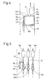
- Fig. 4 shows in a representation according to Fig. 2 the Medium voltage switchgear 20, in addition, the antenna element 28 is shown. This is firmly attached relative to the switchgear 20 and has a course which is approximated to the course of the conductor loop 27. It will be appreciated that the frame leg 30d of the antenna 28 is parallel to the grounded mounting rail 25. The vertical leg 30c of the antenna 28 is parallel to the portion of the rear wall 26 of the switchgear 20.
- the frame leg 30b of the antenna 28 is approximately parallel to the switch 18c and parallel to a portion of the busbar 23a, with only one deviation area 31d in which the Contour of the antenna 28 slightly deviates from the contour of the conductor loop 27.
- the vertical frame leg 30a of the antenna 28 likewise runs substantially parallel to the conductor loop 27, wherein a virtually identical profile is achieved in the region of the protective leadthrough 22a and a deviation region 31a arises in the region of the vertical section of the busbar 23a in which there is a certain, slight deviation of the contour.
- the shape of the antenna 28 is very close to the shape of the existing conductor loop 27 or is almost identical to the given geometry.
- the surface area enclosed by the antenna 28 and the surface area enclosed by the conductor loop 27 is approximately between 0.1 m 2 and 1 m 2 , preferably between 0.25 m 2 and 0.5 m 2 .
- the metal tube 33 may be provided on its outer side with a voltage-resistant insulating hose as impact-resistant and penetration-preventing insulation or, with sufficient distance of the antenna 28 to the conductor loop 27, be kept bare.
- Fig. 5 illustrates that there is a distance d between the antenna 28 and the conductor loop 27, wherein the distance d is preferably selected between 6 cm and 15 cm.
- Fig. 7 shows that the metal tube 33 is formed hollow inside and for receiving a conductor or in the embodiment for receiving second windings 34a and 34b of a conductor 34 is used.
- the two windings 34a, 34b of the conductor 34 are insulated.
- Fig. 8 shows the antenna 28 and the metallic tube 33 in a dash-dotted representation.
- the antenna 28 is connected via a connection 29 to a modem 35, for example via a coaxial line 39.
- the circuitry is chosen such that the inner core 40 of the coaxial cable 39 represents the first turn 34a of the conductor 34 extending within the tube 33 and the shield 41 of the coaxial cable 39 is connected to the corresponding end of the second turn 34b of the conductor 34.
- the second winding 34b is connected to the ground 36 via a solid earth conductor 38.
- a throttle 37 ensures a high-frequency separation, so that the high-frequency signals do not flow to the ground 36.
- Fig. 5 indicates that in the case where a first current I 1 is generated in the antenna 28, an opposing current I 2 is generated due to the electromagnetic coupling in the conductor loop 27.
- the electromagnetic fields caused by the two currents I 1 and I 2 around the two conductors (antenna 28 and conductor loop 27) essentially equal zero, so that the EMC values of the medium-voltage switchgear 20 can be kept very low overall.
- the EMC values of a conventional switchgear 20 can be significantly reduced in this way, since the field strengths are much lower.
- a coupling occurs between the antenna 28 and the conductor loop 27, so that the modem 35 (FIG. Fig. 8 ) on the antenna 28 recorded high-frequency PLC signals through this coupling be modulated directly on the conductor loop 27 and thus on the power supply line 17 d.
- the metal pipe 33 is grounded through the heavy duty earth line 38.
- the two turns 34a, 34b of the conductor 34 within the metal tube 33 are provided, as this results in a mathematical approximate resistance of 50 ohms, which corresponds to the resistance of the current loop 27, so that an impedance matching to minimize level losses is achieved.
- the port 29 may be what's in Fig. 8 is not shown, also be designed as a plug connection and, for example, have two BNC plug-in sockets in the manner of a bayonet lock.
- the modem 35 can be easily connected to the antenna 28 via the coax cable 39 in this way.
- the circuit of the antenna 28 according to Fig. 8 allows a direction independent coupling of PLC signals to the section 21 of the power supply line 17d.
- a directional coupling can be achieved when the connections of the core 40 and the shield 41 of the coaxial cable are exchanged.
- connection unit 29 can then also be associated with a switch which allows switching to the desired operation (transmission or reception mode) of the antenna.
- a switch which allows switching to the desired operation (transmission or reception mode) of the antenna.
- two BNC sockets can be provided so that the modem 35 can be switched by selecting the desired socket in the desired mode.
- the length of the metal tube 33 of the antenna 28 is approximately the size of the wavelength of the PLC signals.
- the vertical frame legs 30a and 30c of the antenna 28 may have a length of 15 cm and the horizontal frame legs 30b and 30d of the antenna 28 may be have a length of 20 cm, which are merely approximate dimensions, which are to be understood by way of example.
- conductor loop 27 may be formed depending on the actual situation in the switchgear 20, also of other components.
- the mounting rail 25 for the bottle 22a according to Fig. 2 also be replaced by a solid metal floor.
- the metal wall 26 may equally be either solid or formed by a wire mesh.
- the feed point in the form of the terminal 29 may be placed at any point of the antenna 28.
- this is arranged as far as possible spaced apart from the bottle 22a for safety reasons and reasons of practicability.
- the coupling of PLC signals according to the invention via an antenna 28 to the existing conductor loop 27 of the switchgear 20 is generally not susceptible to the position of the medium-voltage switch 18c and can thus ensure a permanent PLC signal coupling.
- the electrical components of the switchgear 20 on the side facing away from the bottle 22a of the switch 18c according to Fig. 2 be relieved of high-frequency signals. This also contributes to the reduction of the EMC values.
- a bending of the tube 33 takes place on site, so that an optimal adaptation of the frame shape of the antenna 28 to the existing geometry of the conductor loop 27 can take place.
- the metallic tube 33 is only then equipped with the conductor 34 and with the windings 34a, 34b of the conductor 34 when the tube 33 is already bent on site.
- known threading aids can be used.
- a switchgear 20, which is provided with the device according to the invention for coupling PLC signals, may have different switches 18c, which are manually or alternatively motor-operated. These may be beam network switches or ring switches, depending on the type of circuit of the medium voltage supply line 17. It can be both circuit breaker and circuit breaker.
- switch 18c may also include an in Fig. 1 be switch 18a or 18b.
- To the conductor loop 27 of the switchgear 20 may also include several switches.
- the device according to the invention initially comprises the antenna 28, which in the exemplary embodiment which is not shown, can also only be made of a simple, curved ring conductor.
- the device according to the invention can also comprise an antenna-side connection 29, and, if appropriate, a connection cable 39, as well as optionally also a modem 35.
- a plurality of antennas 28 in a medium-voltage switchgear 20 for Coupling of PLC signals to a plurality of phase conductors of a medium voltage line 17 or to different medium voltage lines 17d, 17e, 17f be provided.
Landscapes
- Engineering & Computer Science (AREA)
- Power Engineering (AREA)
- Computer Networks & Wireless Communication (AREA)
- Signal Processing (AREA)
- Cable Transmission Systems, Equalization Of Radio And Reduction Of Echo (AREA)
- Gas-Insulated Switchgears (AREA)
- Near-Field Transmission Systems (AREA)
- Input Circuits Of Receivers And Coupling Of Receivers And Audio Equipment (AREA)
- Variable-Direction Aerials And Aerial Arrays (AREA)
- Small-Scale Networks (AREA)
Abstract
Description
Die Erfindung betrifft eine Vorrichtung zur Kopplung von PLC-Signalen an eine Spannungsversorgungsleitung gemäß dem Oberbegriff des Anspruches 1.The invention relates to a device for coupling PLC signals to a power supply line according to the preamble of claim 1.
Es ist seit geraumer Zeit bekannt, Daten oder Informationen in Form von PLC- (powerline communication)-Signalen über eine Spannungsversorgungsleitung zu übertragen. Hierfür sind Signalsende- und Empfangseinheiten vorgesehen, so genannte Modems, die an bestimmten Stellen eines Spannungsversorgungsnetzes mit diesem verbunden sind. Die Verbindung kann galvanischer, kapazitiver oder induktiver Art sein. Während die Spannungsversorgungsleitung dazu dient, elektrische Verbraucher mit Betriebsspannung, also niederfrequenter Wechselspannung, beispielsweise im Bereich einiger 10 Hz, zu versorgen, können die PLC-Signale in einem hochfrequenten Frequenzbereich aufmoduliert werden. Die vorhandenen Spannungsversorgungsleitungen können so als Übertragungsmedium für die hochfrequenten PLC-Signale verwendet werden.It has been known for some time to transmit data or information in the form of PLC (powerline communication) signals over a power supply line. For this purpose signal transmitting and receiving units are provided, so-called modems, which are connected at certain points of a power supply network with this. The connection can be galvanic, capacitive or inductive type. While the power supply line is used to supply electrical loads with operating voltage, ie low-frequency AC voltage, for example in the range of a few 10 Hz, the PLC signals can be modulated in a high-frequency frequency range. The existing power supply lines can thus be used as a transmission medium for the high-frequency PLC signals.
Aus der
Nach der stand der Technik
Eine besondere Problematik tritt auf, wenn eine Ankopplung von PLC-Signalen an eine Spannungsversorgungsleitung erfolgen soll, die einen Abschnitt aufweist, der innerhalb einer Schaltanlage verläuft. Dabei kann es sich insbesondere um eine Mittelspannungsschaltanlage handeln, die somit einen Schalter aufweist, der eine Mittelspannungsleitung, typischerweise zur Übertragung von Spannung im Bereich zwischen 1 und 36 kV, schalten oder trennen kann. Bei den bekannten Schaltanlagen kann infolge der vorgegebenen Geometrie der vorhandenen Bauteile der Schaltanlage, zu denen beispielsweise Erdleiter, Befestigungselemente, Stützerdurchführungen, Abschirmgitter, Wandelemente, Stromschiene, Schalter oder andere Bauteile gehören können, eine Leiterschleife gebildet werden. Diese Leiterschleife kann, je nachdem auf welche Art und an welchem Punkt der Leiterschleife die Ankopplung der PLC-Signale bzw. die Verbindung mit dem Modem vorgenommen wird, zu größeren Pegelverlusten und zu ungünstigen EMV-Werten führen.A particular problem occurs when a coupling of PLC signals to a power supply line to take place, which has a section that runs within a switchgear. This may in particular be a medium-voltage switchgear, which thus has a switch which can switch or disconnect a medium-voltage line, typically for the transmission of voltage in the range between 1 and 36 kV. In the known switchgear, a conductor loop may be formed due to the given geometry of the existing components of the switchgear, which may include, for example, earth wire, fasteners, Stützerdurchführungen, Abschirmgitter, wall elements, busbar, switches or other components. Depending on the type and at which point of the conductor loop the coupling of the PLC signals or the connection with the modem is made, this conductor loop can lead to larger level losses and to unfavorable EMC values.
Der Erfindung liegt die Aufgabe zugrunde, eine Vorrichtung gemäß dem Oberbegriff des Anspruches 1 derartig weiterzubilden, dass sie mit geringem Bauaufwand herstellbar und auf einfache Weise montierbar ist.The invention has the object of developing a device according to the preamble of claim 1 such that it can be produced with low construction costs and mounted in a simple manner.
Die Erfindung löst diese Aufgabe mit den Merkmalen des Anspruches 1, insbesondere mit denen des Kennzeichenteils, und ist demgemäß dadurch gekennzeichnet, dass eine in ihrer Form der Leiterschleife nachgebildete Antenne vorgesehen ist, die benachbart der Leiterschleife angeordnet ist.The invention solves this object with the features of claim 1, in particular with those of the characterizing part, and is accordingly characterized in that an imitated in its shape of the conductor loop antenna is provided, which is arranged adjacent to the conductor loop.
Das Prinzip der Erfindung besteht im Wesentlichen darin, anstelle der bekannten induktiven Ankopplung von PLC-Signalen an die Spannungsversorgungsleitung sowie anstelle der bekannten kapazitiven Ankopplung der PLC-Signale an die Spannungsversorgungsleitung nunmehr eine Antennenkopplung vorzusehen. Die in der Schaltanlage vorhandene Leiterschleife wird als erste Antenne benutzt und die gesonderte, in ihrer Form der Leiterschleife nachgebildete Antenne wird als zweite Antenne vorgesehen, wobei die beiden Antennen zusammen ein Antennensystem bilden. Jede der Antennen kann als Sendeantenne und/oder als Empfangsantenne fungieren. Für den Fall, dass eine PLC-Signal-Kopplung an die Spannungsversorgungsleitung im Sendebetrieb eines Modems erfolgen soll, wirkt die Antenne als Sendeantenne und fungiert die Leiterschleife als Empfangsantenne. Im umgekehrten Fall, in dem eine PLC-Signalankopplung an die Spannungsversorgungsleitung derart erfolgen soll, dass ein Modem PLC-Signale, die über die Spannungsversorgungsleitung übertragen werden, empfängt, fungiert die Leiterschleife als Sendeantenne und fungiert die Antenne als Empfangsantenne.The principle of the invention essentially consists in replacing the known inductive coupling of PLC signals to the power supply line and instead of the known ones capacitive coupling of the PLC signals to the power supply line now provide an antenna coupling. The existing in the switchgear conductor loop is used as the first antenna and the separate, imitated in shape of the conductor loop antenna is provided as a second antenna, wherein the two antennas together form an antenna system. Each of the antennas can function as a transmitting antenna and / or as a receiving antenna. In the event that a PLC signal coupling to the power supply line in the transmission mode of a modem is to take place, the antenna acts as a transmitting antenna and the conductor loop acts as a receiving antenna. Conversely, where PLC signal coupling to the power line is to be such that a modem receives PLC signals transmitted over the power line, the loop functions as a transmit antenna and the antenna acts as a receive antenna.
Die Antenne kann im einfachsten Falle ein ringförmig verlaufender Leiter sein, der mit dem Modem verbunden ist. Der Leiter kann vor Ort, also am Einsatz- oder Montageort in der Schaltanlage, in eine Form gebogen werden, die der Form der Leiterschleife nachgebildet ist, das heißt zu der Form der Leiterschleife im Wesentlichen identisch ist oder einer solchen Form angenähert ist. Die in der Schaltanlage vorhandene Leiterschleife ist in der Geometrie der dort vorhandenen Bauteile begründet und somit vorgegeben.The antenna may in the simplest case be a ring-shaped conductor which is connected to the modem. The conductor can be bent on site, ie at the place of use or assembly in the switchgear, in a shape which is modeled on the shape of the conductor loop, that is, is substantially identical to the shape of the conductor loop or approximates such a shape. The conductor loop present in the switchgear is justified in the geometry of the components present there and thus predetermined.
Die Leiterschleife bildet eine im Wesentlichen geschlossene Stromschleife für hochfrequente Wechselspannungen, ist aber für den niederfrequenten Strom unterbrochen. Die Leiterschleife wird von einem Abschnitt der Spannungsversorgungsleitung gebildet, an die die PLC-Signale angekoppelt werden sollen, sowie von weiteren Bauteilen der Schaltanlage. Bestandteil der Leiterschleife können demnach beispielsweise in der Schaltanlage vorhandene Schalter oder Teile eines Schalters, insbesondere eines Mittelspannungsschalters, sein. Auch elektrische Verbindungen zwischen dem Schalter und anderen Bauteilen, insbesondere in Form von Stromschienen, können Bestandteil der Leiterschleife sein. Auch so genannte Stützerdurchführungen, die im Fachjargon als Bottle bezeichnet werden und mit Öl gefüllt dauerhaft eine funktionierende elektrische Isolierung der ölgetränkten Papierschichten der Spannungsversorgungsleitung gewährleisten, können Teil der Leiterschleife sein. Schließlich sind auch Montageschienen für die Stützerdurchführung, die zugleich auch geerdet sein können, Bestandteil der Leiterschleife. Auch Wand- oder Bodenelemente der Schaltanlage, beispielsweise auch Abschirmgitter, die ebenfalls aus Metall bestehen und typischerweise geerdet sind, bilden gemeinsam mit den vorgenannten Bauteilen und dem Abschnitt der Spannungsversorgungsleitung die Leiterschleife aus.The conductor loop forms a substantially closed current loop for high-frequency alternating voltages, but is interrupted for the low-frequency current. The conductor loop is formed by a section of the power supply line to which the PLC signals are to be coupled and by other components of the switchgear. Component of the conductor loop can therefore be, for example, in the switchgear existing switch or parts of a switch, in particular a medium-voltage switch. Also, electrical connections between the switch and other components, in particular in the form of busbars, may be part of the conductor loop. Also so-called supporter bushings, which are referred to in the jargon as a bottle and filled with oil permanently ensure a functioning electrical insulation of the oil-soaked paper layers of the power supply line can be part of the conductor loop. Finally, mounting rails for the support bushing, which can also be earthed at the same time, are part of the conductor loop. Also wall or floor elements of the switchgear, for example, shielding grids, which are also made of metal and are typically grounded, form together with the aforementioned components and the portion of the power supply line, the conductor loop.
Die Erfindung erkennt, dass aufgrund der gegebenen Geometrie einer Schaltanlage dort für hochfrequente Wechselspannung eine Leiterschleife besteht. Die vorhandene Leiterschleife macht sich die Erfindung zunutze, indem durch Anordnung einer Antenne ein Antennensystem aufgebaut wird, was mit denkbar geringem Aufwand möglich ist. Hierzu muss im einfachsten Falle die Antenne nur vor Ort, dem durch die Position der Bauteile vorgegebenen Verlauf der Leiterschleife folgend, gebogen werden und befestigt werden.The invention recognizes that due to the given geometry of a switchgear there is a conductor loop for high-frequency alternating voltage. The existing conductor loop makes use of the invention by an antenna system is constructed by arranging an antenna, which is possible with very little effort. For this purpose, in the simplest case, the antenna must be bent and fixed only locally, following the course of the conductor loop predetermined by the position of the components.
Das Funktionsprinzip des Antennensystems ist wie folgt: Wird ausgehend von dem Modem eine hochfrequente Wechselspannung an die Antenne angelegt, wird hierdurch ein elektromagnetisches Feld in Umfangsrichtung der Antenne erzeugt und abgestrahlt, welches in der Leiterschleife einen entsprechenden, in Gegenrichtung gerichteten Strom hervorruft. Das von dem Modem ausgesandte und an der Antenne anliegende PLC-Signal kann auf diese Weise, praktisch ohne Sendeverluste, auf die Spannungsversorgungsleitung angekoppelt werden, wobei der Begriff "Signalankopplung" im Sinne der Erfindung bi-direktional zu verstehen ist.The operating principle of the antenna system is as follows: Starting from the modem, a high-frequency alternating voltage is applied to the antenna, this generates and emits an electromagnetic field in the circumferential direction of the antenna, which causes a corresponding, directed in the opposite direction current in the conductor loop. The signal emitted by the modem and applied to the antenna PLC signal can be coupled in this way, virtually without transmission losses to the power supply line, the term "signal coupling" in the context of the invention is to be understood bi-directional.
Die erfindungsgemäße Vorrichtung zur Kopplung von PLC-Signalen an eine Spannungsversorgungsleitung umfasst solche Vorrichtungen, die PLC-Signale auf eine Spannungsversorgungsleitung aufkoppeln, solche Vorrichtungen, die PLC-Signale von einer Spannungsversorgungsleitung auskoppeln und solche Vorrichtungen, die sowohl aufkoppeln als auch auskoppeln können und damit bi-direktional arbeiten können. Die unterschiedlichen, möglichen Signalübertragungsrichtungen sind unter dem Begriff "Signalankopplung" zusammengefasst.The device according to the invention for coupling PLC signals to a power supply line comprises such devices that couple PLC signals to a power supply line, such devices that couple PLC signals from a power supply line, and those devices that can both connect and disconnect, and thus bi-directionally -directly can work. The different, possible signal transmission directions are summarized under the term "signal coupling".
Der zuvor beschriebene Effekt bewirkt zugleich, dass die EMV-Werte der Schaltanlage insgesamt deutlich reduziert werden, da sich die Ströme in der Leiterschleife und in der Antenne sowie die zugehörigen elektromagnetischen Felder grundsätzlich zu kompensieren versuchen.At the same time, the effect described above has the effect of significantly reducing the overall EMC values of the switchgear since the currents in the conductor loop and in the antenna as well as the associated electromagnetic fields generally try to compensate.
Anzumerken ist, dass die PLC-Signale etwa in einem Frequenzbereich zwischen 2 MHz und 50 MHz liegen können. Die über die Spannungsversorgungsleitung übertragene Wechselspannung zur Versorgung von Haushalten liegt hingegen im niederfrequenten Spannungsbereich, beispielsweise einiger 10 Hz. Für diese niederfrequente Wechselspannung ist die Leiterschleife selbstverständlich nicht geschlossen und spielt bei diesen geringen Frequenzen auch überhaupt keine Rolle. Erst für Wechselspannung höherer Frequenzen, wie sie für die PLC-Signale relevant sind, stellt sich die vorhandene Leiterschleife als im Wesentlichen geschlossene Leiterschleife dar.It should be noted that the PLC signals may be in a frequency range between 2 MHz and 50 MHz. On the other hand, the AC voltage for supplying households transmitted via the power supply line lies in the low-frequency voltage range, for example a few 10 Hz. For this low-frequency AC voltage, the conductor loop is obviously not closed and plays no role whatsoever at these low frequencies. Only for alternating voltage of higher frequencies, as they are relevant for the PLC signals, the existing conductor loop presents itself as a substantially closed conductor loop.
Gemäß einer vorteilhaften Ausgestaltung der Erfindung ist die Antenne mit einer Signalsende- oder Signalempfangseinheit verbunden. Eine derartige Signalsende- oder Signalempfangseinheit kann von einem herkömmlichen Modem bereitgestellt sein, welches beide Betriebsarten, also sowohl Sendebetrieb als auch Empfangsbetrieb durchführen kann. Die Antenne kann entweder so ausgebildet, insbesondere .geschaltet sein, dass sie sowohl einen Sende- als auch einen Empfangsbetrieb durchführen kann. Es kann auch vorgesehen sein, dass durch einen wahlweise kontaktierbaren Anschluss oder durch einen entsprechenden Schalter eine Einstellung der Antenne vorgenommen werden kann, ob sie in Sende- oder in Empfangsbetrieb arbeiten soll.According to an advantageous embodiment of the invention, the antenna is connected to a signal transmission or signal receiving unit. Such a signal transmission or signal receiving unit may be provided by a conventional modem, which can perform both modes, ie both transmit mode and receive mode. The antenna can either way be formed, in particular switched., That they can perform both a transmitting and a receiving operation. It can also be provided that an adjustment of the antenna can be made by an optionally contactable connection or by a corresponding switch, whether they should work in transmit or receive mode.
Gemäß einer weiteren vorteilhaften Ausgestaltung der Erfindung ist die Leiterschleife für hochfrequente Wechselspannungen geschlossen und für niederfrequente Wechselspannungen offen. Dies bedeutet, dass die hochfrequenten PLC-Signale entlang der Leiterschleife fließen können und auf die Spannungsversorgungsleitung aufmoduliert werden können bzw. ohne Weiteres von der Spannungsversorgungsleitung abgekoppelt werden können, ohne dass dies die Weiterleitung der niederfrequenten Wechselspannung beeinträchtigt.According to a further advantageous embodiment of the invention, the conductor loop for high-frequency alternating voltages is closed and open for low-frequency alternating voltages. This means that the high-frequency PLC signals can flow along the conductor loop and can be modulated onto the voltage supply line or be readily decoupled from the voltage supply line without this affecting the transmission of the low-frequency AC voltage.
Gemäß einer weiteren vorteilhaften Ausgestaltung der Erfindung verläuft die Antenne im Wesentlichen parallel zu der Leiterschleife. Dies bedeutet, dass die Antenne eine Form aufweist, die dem Verlauf der Leiterschleife im Wesentlichen folgt. Eine parallele Anordnung bedeutet zugleich auch, dass der Abstand der Antenne von der Leiterschleife entlang dem Verlauf der Antenne im Wesentlichen konstant ist. Dies ermöglicht ein Antennensystem mit geringen Sendeverlusten.According to a further advantageous embodiment of the invention, the antenna runs substantially parallel to the conductor loop. This means that the antenna has a shape that essentially follows the course of the conductor loop. At the same time, a parallel arrangement also means that the distance of the antenna from the conductor loop along the course of the antenna is substantially constant. This allows an antenna system with low transmission losses.
Gemäß einer weiteren vorteilhaften Ausgestaltung der Erfindung ist die Antenne in einem Abstand zwischen 4 cm und 17 cm, vorteilhafterweise- zwischen 6 cm und 15 cm zu der Leiterschleife angeordnet. Dies ermöglicht einerseits einen besonders sicheren und verlustarmen Betrieb des Antennensystems und zugleich eine hohe Durchschlagsicherheit, z.B. für den Fall, dass die Spannungsversorgungsleitung eine Mittelspannungsleitung ist. Befindet sich die Antenne in einem Abstand von weniger als etwa 10 cm zu der Leiterschleife, kann vorteilhafterweise eine Isolierung, beispielsweise nach Art eines an der Außenumfangsseite der Antenne aufbringbaren Isolierschlauches, vorgesehen werden, wohingegen bei größeren Abständen, beispielsweise oberhalb von 10 cm, auf eine elektrische Isolierung der Außenfläche der Antenne, die metallisch ausgebildet sein kann, verzichtet werden kann.According to a further advantageous embodiment of the invention, the antenna is arranged at a distance between 4 cm and 17 cm, advantageously between 6 cm and 15 cm to the conductor loop. On the one hand, this enables a particularly safe and low-loss operation of the antenna system and at the same time a high level of breakdown safety, for example in the event that the voltage supply line is a medium voltage line. If the antenna is at a distance of less than about 10 cm from the conductor loop, it may be advantageous to provide insulation, for example in the manner of an attachable to the outer peripheral side of the antenna insulating tube, are provided, whereas at larger distances, for example, above 10 cm, on an electrical insulation of the outer surface of the antenna, which may be formed metallic, can be dispensed with.
Gemäß einer weiteren vorteilhaften Ausgestaltung der Erfindung ist die Antenne von einem metallischen Rohr gebildet. Dies ermöglicht eine besonders einfache Bauform und Montage der Antenne, da das Rohr am Montageort in seine endgültige Form biegbar ist und somit in seiner Form der Leiterschleife nachgebildet werden kann. Das metallische Rohr kann beispielsweise aus Kupfer bestehen und im einfachsten Falle die Antenne darstellen. Weiter vorteilhafterweise ist das Rohr allerdings hohl ausgebildet und weist in seinem Inneren einen Leiter auf, der elektrisch von dem metallischen Rohr isoliert ist.According to a further advantageous embodiment of the invention, the antenna is formed by a metallic tube. This allows a particularly simple design and installation of the antenna, since the tube is bendable at the installation in its final form and thus can be simulated in its shape of the conductor loop. The metallic tube may for example consist of copper and represent the antenna in the simplest case. Further advantageously, however, the tube is hollow and has in its interior a conductor which is electrically isolated from the metallic tube.
Gemäß einer weiteren vorteilhaften Ausgestaltung der Erfindung weist das Rohr zwei Enden auf, die sich nicht berühren. Im montierten Zustand ist das Rohr somit zu einem nicht gänzlich geschlossenen Ring geformt, wobei im Bereich der beiden offenen Enden ein Anschluss vorgesehen sein kann. Durch diese offene Stelle können die Leiter auf einfache Weise in das Innere des Rohres hinein bzw. aus dem Inneren des Rohres herausgeführt werden.According to a further advantageous embodiment of the invention, the tube has two ends that do not touch. In the assembled state, the tube is thus formed into a not completely closed ring, wherein a connection can be provided in the region of the two open ends. Through this open position, the conductors can be easily led out into the interior of the tube or from the inside of the tube.
Gemäß einer weiteren vorteilhaften Ausgestaltung der Erfindung ist im Bereich der zwei Enden des Rohres wenigstens ein Anschluss, insbesondere ein Steckanschluss vorgesehen. Der Anschluss ermöglicht insbesondere eine einfache Verbindung der Antenne mit dem Modem. Die Antenne kann auf diese Weise unter Umständen auch als handhabbare Baueinheit zumindest teilweise vorgefertigt werden, was insbesondere vorteilhaft ist, wenn die Geometrie der Leiterschleife im Vorfeld bekannt ist und somit eine werkseitige Biegung des Rohres vorgenommen werden kann.According to a further advantageous embodiment of the invention, at least one connection, in particular a plug connection, is provided in the region of the two ends of the tube. The connection allows in particular a simple connection of the antenna with the modem. Under certain circumstances, the antenna can also be at least partially prefabricated as a manageable structural unit, which is particularly advantageous if the geometry of the conductor loop is known in advance and thus a factory bending of the pipe can be made.
Gemäß einer weiteren vorteilhaften Ausgestaltung der Erfindung ist innerhalb des Rohres ein Leiter mit mindestens einer Windung geführt. Der Leiter ist elektrisch von dem Rohr isoliert.According to a further advantageous embodiment of the invention, a conductor is guided within the tube with at least one turn. The conductor is electrically isolated from the tube.
Gemäß einer weiteren vorteilhaften Ausgestaltung der Erfindung ist innerhalb des Rohres ein Leiter mit zwei Windungen geführt. Dies ermöglicht eine angepasste Impedanz der Antenne an die Impedanz der Leiterschleife.According to a further advantageous embodiment of the invention, a conductor is guided within the tube with two turns. This allows a matched impedance of the antenna to the impedance of the conductor loop.
Gemäß einer weiteren vorteilhaften Ausgestaltung der Erfindung ist die Antenne richtungsneutral geschaltet. Dies bedeutet, dass die Antenne bzw. das Antennensystem aus Antenne und Leiterschleife, ohne dass irgendeine Wahl der Betriebsart vorgenommen werden muss, sowohl im Empfangsbetrieb als auch im Sendebetrieb arbeiten kann. Arbeitet die Antenne im Sendebetrieb, wird das PLC-Signal somit richtungsunabhängig in die Leiterschleife eingespeist und fließt zur Hälfte entlang der Spannungsversorgungsleitung hin zu einer anderen Schaltanlage als auch zu einem anderen etwa hälftigen Anteil über den Schalter zu einer Sammelschiene. Zwar ist bei dieser Ausführungsform der Erfindung mit ca. 50prozentigen Signalpegelverlusten zu rechnen. Andererseits kann auf Betriebswahlschalter oder gesonderte Anschlüsse verzichtet werden.According to a further advantageous embodiment of the invention, the antenna is switched directionally neutral. This means that the aerial or antenna loop antenna system can operate both in receive mode and in transmit mode without having to make any choice of operating mode. Operating the antenna in the transmission mode, the PLC signal is thus fed directionally independent in the conductor loop and flows halfway along the power supply line to another switchgear as well as to another half share about the switch to a busbar. Although in this embodiment of the invention is to be expected with about 50prozentigen signal level losses. On the other hand, can be dispensed operation selector switch or separate connections.
In diesem Zusammenhang sei angemerkt, dass eine Vorrichtung zur Ankopplung von PLC-Signalen, insbesondere eine erfindungsgemäße Vorrichtung mit einer Antenne, vorzugsweise bei jeder Schaltanlage eingesetzt wird, die einen Transformator aufweist, um eine Transformation der hochfrequenten PLC-Signale zu vermeiden. Somit weist ein Spannungsversorgungsnetz typischerweise in regelmäßigen Abständen, beispielsweise etwa alle 300 m bei Betrachtung einer Mittelspannungsleitung, eine Vorrichtung mit einem Verbindungspunkt für ein Modem auf.In this context, it should be noted that a device for coupling PLC signals, in particular a device according to the invention with an antenna, is preferably used in each switchgear having a transformer in order to avoid a transformation of the high-frequency PLC signals. Thus, a power supply network typically has a device with a connection point for a modem at regular intervals, for example, about every 300 meters when considering a medium voltage line.
Gemäß einer alternativen Ausgestaltung der Erfindung ist die Antenne als Richtantenne geschaltet und arbeitet entweder im Sendebetrieb oder im Empfangsbetrieb. Eine entsprechende Schaltung der Antenne als Richtantenne kann auf einfache Weise erfolgen und ermöglicht eine richtungsabhängige Einspeisung der PLC-Signale in die Spannungsversorgungsleitung beispielsweise derart, dass die PLC-Signale praktisch ausschließlich über die Spannungsversorgungsleitung hin in Richtung einer anderen Schaltanlage abfließen und nicht über den Schalter zur Sammelschiene oder zu einem Transformator. Gleichermaßen kann für den Fall, dass die Antenne im Falle einer Schaltung als Richtantenne im Empfangsbetrieb verwendet wird, dafür gesorgt werden, dass auch hier keine Pegelverluste auftreten.According to an alternative embodiment of the invention, the antenna is connected as a directional antenna and operates either in the transmit mode or in the receive mode. A corresponding circuit of the antenna as a directional antenna can be done in a simple manner and allows a direction-dependent feed of the PLC signals in the power supply line, for example, such that the PLC signals flow almost exclusively on the power supply line towards another switchgear and not on the switch to Busbar or to a transformer. Similarly, if the antenna is used in the case of a circuit as a directional antenna in the receive mode, care must be taken to ensure that no level losses occur here as well.
Zur Wahl der gewünschten Betriebsart der Antenne können an der Antenne entweder zwei gesonderte Anschlüsse, die beispielsweise als Sendebetriebsanschluss oder Empfangsbetriebsanschluss gekennzeichnet sind, vorgesehen sein, oder alternativ ein Schalter, der z.B. manuell betätigbar sein kann und eine entsprechende Einstellung der Betriebsart zulässt.In order to select the desired operating mode of the antenna, the antenna can either have two separate connections, which are identified, for example, as a transmission operating terminal or a reception operating connection, or alternatively a switch, e.g. can be manually operated and allows a corresponding adjustment of the operating mode.
Weitere Vorteile der Erfindung ergeben sich aus den nicht zitierten Unteransprüchen sowie anhand der nun folgenden Beschreibung der in den Zeichnungen dargestellten Ausführungsbeispiele. Darin zeigen:
- Fig. 1
- ein schematisches Blockschaltbild eines Ausschnittes eines Spannungsversorgungsnetzes mit einer Hochspannungsschaltanlage und einer Mittelspannungsschaltanlage,
- Fig. 2
- in einer schematischen, teilgeschnittenen Seitenansicht einen Teil einer Mittelspannungsschaltanlage gemäß
Fig. 1 , - Fig. 3
- in einer schematischen Darstellung drei Phasen der Mittelspannungsschaltanlage der
Fig. 2 gemäß Ansichtspfeil 111 inFig. 2 , - Fig. 4
- in einer Darstellung gemäß
Fig. 2 die Mittelspannungsschaltanlage mit einer erfindungsgemäßen Vorrichtung mit einer Antenne, - Fig. 5
- die Mittelspannungsschaltanlage der
Fig. 4 in einer Darstellung gemäßFig. 3 , - Fig. 6
- die Antenne der
Fig. 5 in schematischer Einzeldarstellung, - Fig. 7
- einen Querschnitt durch die Antenne etwa entlang Schnittlinie VII-VII in
Fig. 6 in schematischer Darstellung, und - Fig. 8
- in einer schematischen blockschaltbildartigen Darstellung die Antenne und ein Modem zur Erläuterung der erfindungsgemäßen Schaltung.
- Fig. 1
- a schematic block diagram of a section of a power supply network with a high-voltage switchgear and a medium-voltage switchgear,
- Fig. 2
- in a schematic, partially sectioned side view of a part of a medium voltage switchgear according to
Fig. 1 . - Fig. 3
- in a schematic representation of three phases of the medium voltage switchgear of
Fig. 2 in accordance with view arrow 111 in FIGFig. 2 . - Fig. 4
- in a representation according to
Fig. 2 the medium-voltage switchgear with a device according to the invention with an antenna, - Fig. 5
- the medium voltage switchgear of
Fig. 4 in a representation according toFig. 3 . - Fig. 6
- the antenna of
Fig. 5 in a schematic individual representation, - Fig. 7
- a cross-section through the antenna approximately along section line VII-VII in
Fig. 6 in a schematic representation, and - Fig. 8
- in a schematic block diagram-like representation of the antenna and a modem to explain the circuit according to the invention.
Zunächst soll anhand der
Das Spannungsversorgungsnetz 10 dient der Versorgung von elektrischen Verbrauchern in Industrie und Haushalten mit einer Betriebsspannung einer Niederfrequenz von beispielsweise 50 Hz oder 60 Hz. Von einem nicht dargestellten Kraftwerk wird Elektrizität erzeugt, die über Hochspannungsleitungen 11 a, 11 b beispielsweise als Wechselspannung von ca. 110 kV übertragen wird. Die Hochspannungsleitungen 11a, 11b münden in eine gestrichelt dargestellte Hochspannungsschaltanlage 12, die Schalter 13a, 13b sowie 15a und 15b, gegebenenfalls Sammelschienen 14 und Transformatoren 16a, 16b aufweist, die die Hochspannung von beispielsweise 110 kV auf eine Mittelspannung im Bereich von beispielsweise 10 kV bis 36 kV herunter transformieren. Die Schalter 13a, 13b, 15a, 15b sind vorgesehen, um eine redundante Spannungsversorgung sämtlicher Teilnehmer des Spannungsversorgungsnetzes 10 zu gewährleisten, um beispielsweise Umschaltungen vornehmen zu können oder Leitungszweige zu- oder abschalten zu können, wenn Störungen, beispielsweise durch Blitzschlag oder im Rahmen von Wartungsarbeiten, auftreten. Sämtliche Schalter in
Eine realistische Betriebssituation könnte z.B. eintreten, wenn die Schalter 13a, 15a, 15b und die später noch zu erläuternden Schalter 18a, 18b und 18c geschlossen sind.A realistic operating situation could e.g. occur when the
Die Hochspannungsschaltanlage 12 weist ausgangsseitig zwei Mittelspannungsleitungen 17a und 17b auf. Die Mittelspannungsleitung 17a ist lediglich abgebrochen dargestellt und führt zu nicht dargestellten Netzbereichen des Spannungsversorgungsnetzes 10, z.B. zu einer nicht dargestellten Schaltanlage. Die Mittelspannungsleitung 17b führt zu einer Mittelspannungsschaltanlage 20, die gemäß dem Ausführungsbeispiel der
Die Mittelspannungsschaltanlage 20 ist mit einer weiteren Mittelspannungsleitung 17c verbunden, die zu nicht dargestellten weiteren Mittelspannungsschaltanlagen führen kann oder zu anderen Bereichen des Netzes. Ein Abschnitt der Mittelspannungsleitung, der innerhalb der Mittelspannungsschaltanlage 20 verläuft, ist in
Obwohl die Mittelspannungsschaltanlage 20 der
Aus dem bezüglich
Die in
Zum besseren Verständnis sei darauf hingewiesen, dass die Montageschiene 25 und die Rückwand 26 geerdet und insoweit mit der Abschirmung der Mittelspannungsversorgungsleitung 17d verbunden sind, wohingegen der Schalter 18c und der Abschnitt 21 mit dem Phasen leiter der Mittelspannungsversorgungsleitung 17d verbunden sind.For better understanding, it should be noted that the mounting
Die Ankopplung von PLC-Signalen an die Spannungsversorgungsleitung 17d bzw. an den Abschnitt 21 der Spannungsversorgungsleitung 17d, der innerhalb der Mittelspannungsschaltanlage 20 verläuft, bereitet nun nicht unerhebliche Probleme. Grundsätzlich könnte z.B. eine kapazitive Ankopplung unmittelbar an die unisolierte Stromschiene 23a erfolgen. Gleichermaßen könnte auch ein induktiver Koppler unmittelbar an der Stromschiene 23a angebracht werden. Beide Möglichkeiten führen aber einerseits zu einem relativ schlechten Hochfrequenzverhalten und bedürfen andererseits auch einer spannungsfesten Auslegung bis 60 kV sowie, im Falle eines induktiven Kopplers, einer großen Robustheit gegenüber Betriebsströmen von 400 A bis 600 A und Stromstößen von bis zu 20 kA.The coupling of PLC signals to the
Außerdem treten Probleme auf, weil sich die Übertragungseigenschaft in Abhängigkeit von der Schalterstellung des Schalters 18c ändern kann.In addition, problems arise because the transmission characteristic may change depending on the switch position of the
Die erfindungsgemäße Lösung sieht nun eine in
Zunächst soll anhand der
Bei Betrachtung der
Das Metallrohr 33 kann auf seiner Außenseite mit einem spannungsfesten lsolierschlauch als durchschlagsfeste und durchschlagverhindernde Isolierung versehen sein oder, bei ausreichendem Abstand der Antenne 28 zu der Leiterschleife 27, auch blank gehalten sein.
Anhand der
Anzumerken ist, dass das Metallrohr 33 über die hochbelastbare Erdleitung 38 geerdet ist. Die zwei Windungen 34a, 34b des Leiters 34 innerhalb des Metallrohres 33 sind vorgesehen, da sich hieraus rechnerisch ein ungefährer Widerstand von 50 Ohm ergibt, der dem Widerstand der Stromschleife 27 entspricht, so dass eine Impedanzanpassung zur Minimierung von Pegelverlusten erreicht wird.It should be noted that the
Der Anschluss 29 kann, was in
Die Schaltung der Antenne 28 gemäß
Der Anschlusseinheit 29 kann dann auch ein Schalter zugeordnet sein, der eine Umschaltung in den gewünschten Betrieb (Sendebetrieb oder Empfangsbetrieb) der Antenne ermöglicht. Gleichermaßen können auch zwei BNC-Steckbuchsen vorgesehen sein, so dass das Modem 35 durch Wahl der gewünschten Steckbuchse in die gewünschte Betriebsart schaltbar ist.The
Anzumerken ist, dass die Länge des Metallrohres 33 der Antenne 28 ungefähr in der Größe der Wellenlänge der PLC-Signale liegt. Die Vertikal-Rahmenschenkel 30a und 30c der Antenne 28 können beispielsweise eine Länge von 15 cm und die horizontalen Rahmenschenkel 30b und 30d der Antenne 28 können beispielsweise eine Länge von 20 cm aufweisen, wobei dies lediglich ungefähre Maßangaben sind, die beispielhaft zu verstehen sind.It should be noted that the length of the
Die in
Der Einspeisepunkt in Form des Anschlusses 29 kann zwar an beliebiger Stelle der Antenne 28 platziert sein. Vorteilhafterweise ist dieser aber aus Sicherheitsgründen sowie aus Praktikabilitätsgründen möglichst weit beabstandet von der Bottle 22a angeordnet.Although the feed point in the form of the terminal 29 may be placed at any point of the
Die erfindungsgemäße Ankopplung von PLC-Signalen über eine Antenne 28 an die bestehende Leiterschleife 27 der Schaltanlage 20 ist insgesamt unanfällig für die Stellung des Mittelspannungsschalters 18c und kann insoweit eine dauerhafte PLC-Signalankopplung gewährleisten. Im Falle einer richtungsabhängigen Einstrahlung der PLC-Signale über die Antenne 28 in die Mittelspannungsversorgungsleitung 17d können die elektrischen Bauteile der Schaltanlage 20 auf der der Bottle 22a abgewandten Seite des Schalters 18c gemäß
Eine Biegung des Rohres 33 findet vor Ort statt, so dass eine optimale Anpassung der Rahmenform der Antenne 28 an die vorhandene Geometrie der Leiterschleife 27 erfolgen kann. Weiter vorzugsweise wird das metallische Rohr 33 erst dann mit dem Leiter 34 bzw. mit den Windungen 34a, 34b des Leiters 34 bestückt, wenn das Rohr 33 bereits vor Ort gebogen ist. Hierfür können bekannte Einfädelhilfen verwendet werden. Dabei besteht auch die Möglichkeit, die beiden Windungen 34a, 34b des Leiters 34a gemeinsam, in unverbundenem Zustand als zwei Leiterabschnitte, durch das Rohr 33 hindurchzuführen und erst nachfolgend entsprechend anzuschließen.A bending of the
Eine Schaltanlage 20, die mit der erfindungsgemäßen Vorrichtung zur Ankopplung von PLC-Signalen versehen ist, kann unterschiedliche Schalter 18c aufweisen, die manuell oder alternativ auch motorisch betätigbar sind. Es kann sich dabei um Strahlennetz-Schalter oder Ringschalter, je nach Art der Schaltung der Mittelspannungsversorgungsleitung 17, handeln. Es können sowohl Trennschalter als auch Leistungsschalter sein.A
Ergänzend sei angemerkt, dass die in den
Die erfindungsgemäße Vorrichtung umfasst zunächst die Antenne 28, die bei dem nicht dargestellten Ausführungsbeispiel auch nur aus einem einfachen, in Ringform gebogenen Leiter stehen kann. Die erfindungsgemäße Vorrichtung kann auch einen antennenseitigen Anschluss 29, sowie gegebenenfalls ein Verbindungskabel 39, sowie weiter gegebenenfalls auch ein Modem 35 umfassen.The device according to the invention initially comprises the
Im Falle einer drei Phasenleiter 17d, 17e, 17f aufweisenden Mittelspannungsschaltanlage 20, wie dies
Claims (19)
- Device for coupling PLC signals to a voltage supply line (17d), which has a section (21) which runs within a switchgear (20), in particular within a medium-voltage switchgear, and forms a conductor loop (27) together with other electrically conductive components of the switchgear, such as earth wires (25), fastening elements, support feedthroughs (22a), shield grids, wall elements (26), current buses (23a), switches (18c), characterised in that an antenna (28) is provided, whose shape follows that of the conductor loop (27) and is arranged adjacent to the conductor loop.
- Device according to Claim 1, characterised in that the antenna (28) is connected to a signal transmitting and/or signal receiving unit (35).
- Device according to Claim 1 or 2, characterised in that the conductor loop (27) is closed for highfrequency alternating voltages.
- Device according to one of Claims 1 to 3,
characterised in that the conductor loop (27) is open for low-frequency alternating voltages. - Device according to one of the preceding claims, characterised in that the antenna (28) runs essentially parallel to the conductor loop (27).
- Device according to one of the preceding claims, characterised in that the antenna (28) is arranged at a distance (d) of between 4 and 17 cm from the conductor loop (27).
- Device according to Claim 6, characterised in that the antenna (28) is arranged at a distance (d) of between 6 and 15 cm from the conductor loop (27).
- Device according to one of the preceding claims, characterised in that the antenna (28) is formed by a metallic tube (33).
- Device according to Claim 8, characterised in that the tube (33) is flexible in its final form (Fig. 6) at the site of installation.
- Device according to Claim 8 or 9, characterised in that the tube (33) has two ends (32a, 32b) which do not touch.
- Device according to Claim 10, characterised in that at least one connection (29), for example a plug-in connection, in particular for feeding in the signal, is provided in the region of the two ends (32a, 32b).
- Device according to one of Claims 8 to 11, characterised in that the tube (33) is configured to be insulated on its outer side, is in particular provided with voltage-proof insulating hose.
- Device according to one of Claims 8 to 11, characterised in that the tube (33) is configured to be uninsulated on its outer side.
- Device according to one of Claims 8 to 13, characterised in that a conductor (34) with at least one winding (34a, 34b) is routed within the tube (33).
- Device according to Claim 14, characterised in that a conductor (34) with two windings (34a, 34b) is routed within the tube (33).
- Device according to one of the preceding claims, characterised in that the antenna (28) is connected in a directionally neutral manner (Fig. 8).
- Device according to one of Claims 1 to 15, characterised in that the antenna (28) is connected as a directional antenna and operates either in transmission mode or reception mode.
- Device according to Claim 17, characterised in that two connections are provided on the antenna (28) for selecting the desired operating mode of the antenna.
- Device according to Claim 17, characterised in that a switch is provided for selecting the desired operating mode of the antenna (28).
Applications Claiming Priority (1)
| Application Number | Priority Date | Filing Date | Title |
|---|---|---|---|
| DE102005022270A DE102005022270A1 (en) | 2005-05-10 | 2005-05-10 | Device for coupling PLC signals to a power supply line |
Publications (2)
| Publication Number | Publication Date |
|---|---|
| EP1722489A1 EP1722489A1 (en) | 2006-11-15 |
| EP1722489B1 true EP1722489B1 (en) | 2009-04-15 |
Family
ID=36576039
Family Applications (1)
| Application Number | Title | Priority Date | Filing Date |
|---|---|---|---|
| EP06009033A Not-in-force EP1722489B1 (en) | 2005-05-10 | 2006-05-02 | Apparatus for coupling communication signals in a power line |
Country Status (5)
| Country | Link |
|---|---|
| EP (1) | EP1722489B1 (en) |
| AT (1) | ATE429081T1 (en) |
| DE (2) | DE102005022270A1 (en) |
| ES (1) | ES2325553T3 (en) |
| PT (1) | PT1722489E (en) |
Families Citing this family (1)
| Publication number | Priority date | Publication date | Assignee | Title |
|---|---|---|---|---|
| DE102019001194A1 (en) | 2019-02-18 | 2019-08-22 | Daimler Ag | Method for measuring a screen attenuation of a battery housing with a bus bar |
Family Cites Families (4)
| Publication number | Priority date | Publication date | Assignee | Title |
|---|---|---|---|---|
| DE449876C (en) * | 1927-09-24 | Erich F Huth G M B H Dr | Coupling arrangement for message transmission along lines | |
| DE19821045A1 (en) * | 1998-05-11 | 1999-11-18 | Abb Research Ltd | Device and method for coupling signals in high and medium voltage lines |
| DE10061584B4 (en) * | 2000-12-11 | 2004-02-05 | Siemens Ag | Arrangement and method for data communication in a power distribution network |
| DE10246261A1 (en) * | 2002-10-02 | 2004-04-22 | Eichhoff Gmbh | Device for the inductive coupling of electrical signals to a power supply line and processing method for a tape winding |
-
2005
- 2005-05-10 DE DE102005022270A patent/DE102005022270A1/en not_active Ceased
-
2006
- 2006-05-02 AT AT06009033T patent/ATE429081T1/en not_active IP Right Cessation
- 2006-05-02 ES ES06009033T patent/ES2325553T3/en active Active
- 2006-05-02 EP EP06009033A patent/EP1722489B1/en not_active Not-in-force
- 2006-05-02 DE DE502006003416T patent/DE502006003416D1/en active Active
- 2006-05-02 PT PT06009033T patent/PT1722489E/en unknown
Also Published As
| Publication number | Publication date |
|---|---|
| PT1722489E (en) | 2009-06-26 |
| DE102005022270A1 (en) | 2006-11-30 |
| DE502006003416D1 (en) | 2009-05-28 |
| ES2325553T3 (en) | 2009-09-08 |
| EP1722489A1 (en) | 2006-11-15 |
| ATE429081T1 (en) | 2009-05-15 |
Similar Documents
| Publication | Publication Date | Title |
|---|---|---|
| DE2127193C3 (en) | Coupling unit for coupling twin cores running insulated in the phase cable of high-voltage lines as carrier frequency lines to communication devices or cables | |
| DE3203689A1 (en) | NETWORK MESSAGE CONNECTION SYSTEM USING THE ZERO AND EARTH PROTECTIVE LADDERS OF A HOUSEHOLD BRANCH | |
| EP1312172B1 (en) | Method for transmitting high-frequency signals on low-voltage networks and corresponding system | |
| EP1645048B1 (en) | Inductive coupling circuit and telecommunication method by sheathed cables of an electrical current distribution network | |
| DE102011013330B3 (en) | Single-phase feeding arrangement and method for supplying a supply line of an alternating current track with single-phase alternating current | |
| EP1722489B1 (en) | Apparatus for coupling communication signals in a power line | |
| AT404197B (en) | CIRCUIT ARRANGEMENT FOR A HIGH VOLTAGE THREE-PHASE CABLE CONSTRUCTED FROM SINGLE-CORE CABLES | |
| DE202005007632U1 (en) | PLC system coupler uses transmit receiver connected to metal tube antenna close to mains supply circuit in switch installation | |
| DE102006020029B4 (en) | Adaptive, capacitive coupling circuit and method for message transmission via shielded power cables of an electrical power distribution network | |
| EP1435141B1 (en) | Arrangement for connecting a powerline data transmission device or a repeater in a live low-voltage mains network | |
| WO2006105878A1 (en) | Electrical switchgear | |
| DE919718C (en) | Antenna arrangement | |
| EP0952681A2 (en) | Capacitive coupling cable for signal coupling onto power lines | |
| EP1683402B1 (en) | Busbar trunking system | |
| WO2001093453A1 (en) | Electrical coupling unit for high frequency data streams | |
| AT410995B (en) | Voltage supply device | |
| DE3410726A1 (en) | Single-phase metal-encapsulated alternating-current system | |
| EP1468504A1 (en) | Coupling device | |
| DE102011018313B4 (en) | Antenna system with two rotationally symmetrical, coaxial antennas | |
| DE1933813C3 (en) | Communication device in high-voltage overhead line networks | |
| DE609814C (en) | Device to shut off parts of electrical power distribution networks in which there are cable routes against the ingress of superimposed frequencies | |
| WO2019068438A1 (en) | Assembly for connecting to a high-voltage grid | |
| DE1247426B (en) | Device for interconnecting several antennas | |
| DE19853976A1 (en) | Data transmission system using cables | |
| DE6605883U (en) | DEVICE FOR CONNECTING AN ELECTRICAL CABLE TO A HOSE |
Legal Events
| Date | Code | Title | Description |
|---|---|---|---|
| PUAI | Public reference made under article 153(3) epc to a published international application that has entered the european phase |
Free format text: ORIGINAL CODE: 0009012 |
|
| AK | Designated contracting states |
Kind code of ref document: A1 Designated state(s): AT BE BG CH CY CZ DE DK EE ES FI FR GB GR HU IE IS IT LI LT LU LV MC NL PL PT RO SE SI SK TR |
|
| AX | Request for extension of the european patent |
Extension state: AL BA HR MK YU |
|
| 17P | Request for examination filed |
Effective date: 20070507 |
|
| AKX | Designation fees paid |
Designated state(s): AT BE BG CH CY CZ DE DK EE ES FI FR GB GR HU IE IS IT LI LT LU LV MC NL PL PT RO SE SI SK TR |
|
| GRAP | Despatch of communication of intention to grant a patent |
Free format text: ORIGINAL CODE: EPIDOSNIGR1 |
|
| GRAS | Grant fee paid |
Free format text: ORIGINAL CODE: EPIDOSNIGR3 |
|
| GRAA | (expected) grant |
Free format text: ORIGINAL CODE: 0009210 |
|
| AK | Designated contracting states |
Kind code of ref document: B1 Designated state(s): AT BE BG CH CY CZ DE DK EE ES FI FR GB GR HU IE IS IT LI LT LU LV MC NL PL PT RO SE SI SK TR |
|
| REG | Reference to a national code |
Ref country code: CH Ref legal event code: EP Ref country code: GB Ref legal event code: FG4D Free format text: NOT ENGLISH |
|
| REG | Reference to a national code |
Ref country code: IE Ref legal event code: FG4D |
|
| REF | Corresponds to: |
Ref document number: 502006003416 Country of ref document: DE Date of ref document: 20090528 Kind code of ref document: P |
|
| REG | Reference to a national code |
Ref country code: PT Ref legal event code: SC4A Free format text: AVAILABILITY OF NATIONAL TRANSLATION Effective date: 20090619 |
|
| PGFP | Annual fee paid to national office [announced via postgrant information from national office to epo] |
Ref country code: AT Payment date: 20090528 Year of fee payment: 4 |
|
| REG | Reference to a national code |
Ref country code: ES Ref legal event code: FG2A Ref document number: 2325553 Country of ref document: ES Kind code of ref document: T3 |
|
| NLV1 | Nl: lapsed or annulled due to failure to fulfill the requirements of art. 29p and 29m of the patents act | ||
| PG25 | Lapsed in a contracting state [announced via postgrant information from national office to epo] |
Ref country code: FI Free format text: LAPSE BECAUSE OF FAILURE TO SUBMIT A TRANSLATION OF THE DESCRIPTION OR TO PAY THE FEE WITHIN THE PRESCRIBED TIME-LIMIT Effective date: 20090415 Ref country code: LT Free format text: LAPSE BECAUSE OF FAILURE TO SUBMIT A TRANSLATION OF THE DESCRIPTION OR TO PAY THE FEE WITHIN THE PRESCRIBED TIME-LIMIT Effective date: 20090415 |
|
| BERE | Be: lapsed |
Owner name: EICHHOFF G.M.B.H. Effective date: 20090531 |
|
| PG25 | Lapsed in a contracting state [announced via postgrant information from national office to epo] |
Ref country code: SI Free format text: LAPSE BECAUSE OF FAILURE TO SUBMIT A TRANSLATION OF THE DESCRIPTION OR TO PAY THE FEE WITHIN THE PRESCRIBED TIME-LIMIT Effective date: 20090415 Ref country code: IS Free format text: LAPSE BECAUSE OF FAILURE TO SUBMIT A TRANSLATION OF THE DESCRIPTION OR TO PAY THE FEE WITHIN THE PRESCRIBED TIME-LIMIT Effective date: 20090815 Ref country code: LV Free format text: LAPSE BECAUSE OF FAILURE TO SUBMIT A TRANSLATION OF THE DESCRIPTION OR TO PAY THE FEE WITHIN THE PRESCRIBED TIME-LIMIT Effective date: 20090415 Ref country code: NL Free format text: LAPSE BECAUSE OF FAILURE TO SUBMIT A TRANSLATION OF THE DESCRIPTION OR TO PAY THE FEE WITHIN THE PRESCRIBED TIME-LIMIT Effective date: 20090415 Ref country code: SE Free format text: LAPSE BECAUSE OF FAILURE TO SUBMIT A TRANSLATION OF THE DESCRIPTION OR TO PAY THE FEE WITHIN THE PRESCRIBED TIME-LIMIT Effective date: 20090715 Ref country code: PL Free format text: LAPSE BECAUSE OF FAILURE TO SUBMIT A TRANSLATION OF THE DESCRIPTION OR TO PAY THE FEE WITHIN THE PRESCRIBED TIME-LIMIT Effective date: 20090415 |
|
| REG | Reference to a national code |
Ref country code: IE Ref legal event code: FD4D |
|
| PG25 | Lapsed in a contracting state [announced via postgrant information from national office to epo] |
Ref country code: MC Free format text: LAPSE BECAUSE OF NON-PAYMENT OF DUE FEES Effective date: 20090531 |
|
| PG25 | Lapsed in a contracting state [announced via postgrant information from national office to epo] |
Ref country code: CZ Free format text: LAPSE BECAUSE OF FAILURE TO SUBMIT A TRANSLATION OF THE DESCRIPTION OR TO PAY THE FEE WITHIN THE PRESCRIBED TIME-LIMIT Effective date: 20090415 Ref country code: DK Free format text: LAPSE BECAUSE OF FAILURE TO SUBMIT A TRANSLATION OF THE DESCRIPTION OR TO PAY THE FEE WITHIN THE PRESCRIBED TIME-LIMIT Effective date: 20090415 Ref country code: RO Free format text: LAPSE BECAUSE OF FAILURE TO SUBMIT A TRANSLATION OF THE DESCRIPTION OR TO PAY THE FEE WITHIN THE PRESCRIBED TIME-LIMIT Effective date: 20090415 Ref country code: IE Free format text: LAPSE BECAUSE OF FAILURE TO SUBMIT A TRANSLATION OF THE DESCRIPTION OR TO PAY THE FEE WITHIN THE PRESCRIBED TIME-LIMIT Effective date: 20090415 Ref country code: EE Free format text: LAPSE BECAUSE OF FAILURE TO SUBMIT A TRANSLATION OF THE DESCRIPTION OR TO PAY THE FEE WITHIN THE PRESCRIBED TIME-LIMIT Effective date: 20090415 |
|
| PLBE | No opposition filed within time limit |
Free format text: ORIGINAL CODE: 0009261 |
|
| STAA | Information on the status of an ep patent application or granted ep patent |
Free format text: STATUS: NO OPPOSITION FILED WITHIN TIME LIMIT |
|
| PG25 | Lapsed in a contracting state [announced via postgrant information from national office to epo] |
Ref country code: SK Free format text: LAPSE BECAUSE OF FAILURE TO SUBMIT A TRANSLATION OF THE DESCRIPTION OR TO PAY THE FEE WITHIN THE PRESCRIBED TIME-LIMIT Effective date: 20090415 |
|
| 26N | No opposition filed |
Effective date: 20100118 |
|
| PG25 | Lapsed in a contracting state [announced via postgrant information from national office to epo] |
Ref country code: BG Free format text: LAPSE BECAUSE OF FAILURE TO SUBMIT A TRANSLATION OF THE DESCRIPTION OR TO PAY THE FEE WITHIN THE PRESCRIBED TIME-LIMIT Effective date: 20090715 |
|
| PG25 | Lapsed in a contracting state [announced via postgrant information from national office to epo] |
Ref country code: BE Free format text: LAPSE BECAUSE OF NON-PAYMENT OF DUE FEES Effective date: 20090531 |
|
| PGFP | Annual fee paid to national office [announced via postgrant information from national office to epo] |
Ref country code: ES Payment date: 20100527 Year of fee payment: 5 Ref country code: FR Payment date: 20100527 Year of fee payment: 5 Ref country code: PT Payment date: 20100521 Year of fee payment: 5 |
|
| PGFP | Annual fee paid to national office [announced via postgrant information from national office to epo] |
Ref country code: DE Payment date: 20100527 Year of fee payment: 5 Ref country code: IT Payment date: 20100528 Year of fee payment: 5 |
|
| PG25 | Lapsed in a contracting state [announced via postgrant information from national office to epo] |
Ref country code: GR Free format text: LAPSE BECAUSE OF FAILURE TO SUBMIT A TRANSLATION OF THE DESCRIPTION OR TO PAY THE FEE WITHIN THE PRESCRIBED TIME-LIMIT Effective date: 20090716 |
|
| REG | Reference to a national code |
Ref country code: CH Ref legal event code: PL |
|
| GBPC | Gb: european patent ceased through non-payment of renewal fee |
Effective date: 20100502 |
|
| PG25 | Lapsed in a contracting state [announced via postgrant information from national office to epo] |
Ref country code: LI Free format text: LAPSE BECAUSE OF NON-PAYMENT OF DUE FEES Effective date: 20100531 Ref country code: CH Free format text: LAPSE BECAUSE OF NON-PAYMENT OF DUE FEES Effective date: 20100531 |
|
| PG25 | Lapsed in a contracting state [announced via postgrant information from national office to epo] |
Ref country code: LU Free format text: LAPSE BECAUSE OF NON-PAYMENT OF DUE FEES Effective date: 20090502 |
|
| PG25 | Lapsed in a contracting state [announced via postgrant information from national office to epo] |
Ref country code: HU Free format text: LAPSE BECAUSE OF FAILURE TO SUBMIT A TRANSLATION OF THE DESCRIPTION OR TO PAY THE FEE WITHIN THE PRESCRIBED TIME-LIMIT Effective date: 20091016 |
|
| PG25 | Lapsed in a contracting state [announced via postgrant information from national office to epo] |
Ref country code: GB Free format text: LAPSE BECAUSE OF NON-PAYMENT OF DUE FEES Effective date: 20100502 |
|
| PG25 | Lapsed in a contracting state [announced via postgrant information from national office to epo] |
Ref country code: TR Free format text: LAPSE BECAUSE OF FAILURE TO SUBMIT A TRANSLATION OF THE DESCRIPTION OR TO PAY THE FEE WITHIN THE PRESCRIBED TIME-LIMIT Effective date: 20090415 |
|
| PG25 | Lapsed in a contracting state [announced via postgrant information from national office to epo] |
Ref country code: CY Free format text: LAPSE BECAUSE OF FAILURE TO SUBMIT A TRANSLATION OF THE DESCRIPTION OR TO PAY THE FEE WITHIN THE PRESCRIBED TIME-LIMIT Effective date: 20090415 |
|
| REG | Reference to a national code |
Ref country code: PT Ref legal event code: MM4A Free format text: LAPSE DUE TO NON-PAYMENT OF FEES Effective date: 20111102 |
|
| PG25 | Lapsed in a contracting state [announced via postgrant information from national office to epo] |
Ref country code: PT Free format text: LAPSE BECAUSE OF NON-PAYMENT OF DUE FEES Effective date: 20111102 |
|
| REG | Reference to a national code |
Ref country code: AT Ref legal event code: MM01 Ref document number: 429081 Country of ref document: AT Kind code of ref document: T Effective date: 20110502 |
|
| REG | Reference to a national code |
Ref country code: FR Ref legal event code: ST Effective date: 20120131 |
|
| PG25 | Lapsed in a contracting state [announced via postgrant information from national office to epo] |
Ref country code: AT Free format text: LAPSE BECAUSE OF NON-PAYMENT OF DUE FEES Effective date: 20110502 Ref country code: IT Free format text: LAPSE BECAUSE OF NON-PAYMENT OF DUE FEES Effective date: 20110502 |
|
| REG | Reference to a national code |
Ref country code: DE Ref legal event code: R119 Ref document number: 502006003416 Country of ref document: DE Effective date: 20111201 |
|
| PG25 | Lapsed in a contracting state [announced via postgrant information from national office to epo] |
Ref country code: FR Free format text: LAPSE BECAUSE OF NON-PAYMENT OF DUE FEES Effective date: 20110531 |
|
| PG25 | Lapsed in a contracting state [announced via postgrant information from national office to epo] |
Ref country code: DE Free format text: LAPSE BECAUSE OF NON-PAYMENT OF DUE FEES Effective date: 20111201 |
|
| REG | Reference to a national code |
Ref country code: ES Ref legal event code: FD2A Effective date: 20131029 |
|
| PG25 | Lapsed in a contracting state [announced via postgrant information from national office to epo] |
Ref country code: ES Free format text: LAPSE BECAUSE OF NON-PAYMENT OF DUE FEES Effective date: 20110503 |