EP1722109A2 - Anti jerk valve - Google Patents
Anti jerk valve Download PDFInfo
- Publication number
- EP1722109A2 EP1722109A2 EP06009372A EP06009372A EP1722109A2 EP 1722109 A2 EP1722109 A2 EP 1722109A2 EP 06009372 A EP06009372 A EP 06009372A EP 06009372 A EP06009372 A EP 06009372A EP 1722109 A2 EP1722109 A2 EP 1722109A2
- Authority
- EP
- European Patent Office
- Prior art keywords
- valve
- pressure
- fluid
- load
- ports
- Prior art date
- Legal status (The legal status is an assumption and is not a legal conclusion. Google has not performed a legal analysis and makes no representation as to the accuracy of the status listed.)
- Granted
Links
Images


Classifications
-
- B—PERFORMING OPERATIONS; TRANSPORTING
- B62—LAND VEHICLES FOR TRAVELLING OTHERWISE THAN ON RAILS
- B62D—MOTOR VEHICLES; TRAILERS
- B62D12/00—Steering specially adapted for vehicles operating in tandem or having pivotally connected frames
-
- B—PERFORMING OPERATIONS; TRANSPORTING
- B62—LAND VEHICLES FOR TRAVELLING OTHERWISE THAN ON RAILS
- B62D—MOTOR VEHICLES; TRAILERS
- B62D5/00—Power-assisted or power-driven steering
- B62D5/06—Power-assisted or power-driven steering fluid, i.e. using a pressurised fluid for most or all the force required for steering a vehicle
- B62D5/09—Power-assisted or power-driven steering fluid, i.e. using a pressurised fluid for most or all the force required for steering a vehicle characterised by means for actuating valves
- B62D5/093—Telemotor driven by steering wheel movement
-
- F—MECHANICAL ENGINEERING; LIGHTING; HEATING; WEAPONS; BLASTING
- F15—FLUID-PRESSURE ACTUATORS; HYDRAULICS OR PNEUMATICS IN GENERAL
- F15B—SYSTEMS ACTING BY MEANS OF FLUIDS IN GENERAL; FLUID-PRESSURE ACTUATORS, e.g. SERVOMOTORS; DETAILS OF FLUID-PRESSURE SYSTEMS, NOT OTHERWISE PROVIDED FOR
- F15B11/00—Servomotor systems without provision for follow-up action; Circuits therefor
- F15B11/02—Systems essentially incorporating special features for controlling the speed or actuating force of an output member
- F15B11/04—Systems essentially incorporating special features for controlling the speed or actuating force of an output member for controlling the speed
- F15B11/044—Systems essentially incorporating special features for controlling the speed or actuating force of an output member for controlling the speed by means in the return line, i.e. "meter out"
- F15B11/0445—Systems essentially incorporating special features for controlling the speed or actuating force of an output member for controlling the speed by means in the return line, i.e. "meter out" with counterbalance valves, e.g. to prevent overrunning or for braking
-
- F—MECHANICAL ENGINEERING; LIGHTING; HEATING; WEAPONS; BLASTING
- F15—FLUID-PRESSURE ACTUATORS; HYDRAULICS OR PNEUMATICS IN GENERAL
- F15B—SYSTEMS ACTING BY MEANS OF FLUIDS IN GENERAL; FLUID-PRESSURE ACTUATORS, e.g. SERVOMOTORS; DETAILS OF FLUID-PRESSURE SYSTEMS, NOT OTHERWISE PROVIDED FOR
- F15B2211/00—Circuits for servomotor systems
- F15B2211/30—Directional control
- F15B2211/305—Directional control characterised by the type of valves
- F15B2211/30505—Non-return valves, i.e. check valves
- F15B2211/3051—Cross-check valves
-
- F—MECHANICAL ENGINEERING; LIGHTING; HEATING; WEAPONS; BLASTING
- F15—FLUID-PRESSURE ACTUATORS; HYDRAULICS OR PNEUMATICS IN GENERAL
- F15B—SYSTEMS ACTING BY MEANS OF FLUIDS IN GENERAL; FLUID-PRESSURE ACTUATORS, e.g. SERVOMOTORS; DETAILS OF FLUID-PRESSURE SYSTEMS, NOT OTHERWISE PROVIDED FOR
- F15B2211/00—Circuits for servomotor systems
- F15B2211/50—Pressure control
- F15B2211/52—Pressure control characterised by the type of actuation
- F15B2211/528—Pressure control characterised by the type of actuation actuated by fluid pressure
-
- F—MECHANICAL ENGINEERING; LIGHTING; HEATING; WEAPONS; BLASTING
- F15—FLUID-PRESSURE ACTUATORS; HYDRAULICS OR PNEUMATICS IN GENERAL
- F15B—SYSTEMS ACTING BY MEANS OF FLUIDS IN GENERAL; FLUID-PRESSURE ACTUATORS, e.g. SERVOMOTORS; DETAILS OF FLUID-PRESSURE SYSTEMS, NOT OTHERWISE PROVIDED FOR
- F15B2211/00—Circuits for servomotor systems
- F15B2211/50—Pressure control
- F15B2211/55—Pressure control for limiting a pressure up to a maximum pressure, e.g. by using a pressure relief valve
-
- F—MECHANICAL ENGINEERING; LIGHTING; HEATING; WEAPONS; BLASTING
- F15—FLUID-PRESSURE ACTUATORS; HYDRAULICS OR PNEUMATICS IN GENERAL
- F15B—SYSTEMS ACTING BY MEANS OF FLUIDS IN GENERAL; FLUID-PRESSURE ACTUATORS, e.g. SERVOMOTORS; DETAILS OF FLUID-PRESSURE SYSTEMS, NOT OTHERWISE PROVIDED FOR
- F15B2211/00—Circuits for servomotor systems
- F15B2211/50—Pressure control
- F15B2211/57—Control of a differential pressure
-
- F—MECHANICAL ENGINEERING; LIGHTING; HEATING; WEAPONS; BLASTING
- F15—FLUID-PRESSURE ACTUATORS; HYDRAULICS OR PNEUMATICS IN GENERAL
- F15B—SYSTEMS ACTING BY MEANS OF FLUIDS IN GENERAL; FLUID-PRESSURE ACTUATORS, e.g. SERVOMOTORS; DETAILS OF FLUID-PRESSURE SYSTEMS, NOT OTHERWISE PROVIDED FOR
- F15B2211/00—Circuits for servomotor systems
- F15B2211/70—Output members, e.g. hydraulic motors or cylinders or control therefor
- F15B2211/71—Multiple output members, e.g. multiple hydraulic motors or cylinders
- F15B2211/7107—Multiple output members, e.g. multiple hydraulic motors or cylinders the output members being mechanically linked
-
- F—MECHANICAL ENGINEERING; LIGHTING; HEATING; WEAPONS; BLASTING
- F15—FLUID-PRESSURE ACTUATORS; HYDRAULICS OR PNEUMATICS IN GENERAL
- F15B—SYSTEMS ACTING BY MEANS OF FLUIDS IN GENERAL; FLUID-PRESSURE ACTUATORS, e.g. SERVOMOTORS; DETAILS OF FLUID-PRESSURE SYSTEMS, NOT OTHERWISE PROVIDED FOR
- F15B2211/00—Circuits for servomotor systems
- F15B2211/70—Output members, e.g. hydraulic motors or cylinders or control therefor
- F15B2211/71—Multiple output members, e.g. multiple hydraulic motors or cylinders
- F15B2211/7114—Multiple output members, e.g. multiple hydraulic motors or cylinders with direct connection between the chambers of different actuators
- F15B2211/7128—Multiple output members, e.g. multiple hydraulic motors or cylinders with direct connection between the chambers of different actuators the chambers being connected in parallel
-
- F—MECHANICAL ENGINEERING; LIGHTING; HEATING; WEAPONS; BLASTING
- F15—FLUID-PRESSURE ACTUATORS; HYDRAULICS OR PNEUMATICS IN GENERAL
- F15B—SYSTEMS ACTING BY MEANS OF FLUIDS IN GENERAL; FLUID-PRESSURE ACTUATORS, e.g. SERVOMOTORS; DETAILS OF FLUID-PRESSURE SYSTEMS, NOT OTHERWISE PROVIDED FOR
- F15B2211/00—Circuits for servomotor systems
- F15B2211/80—Other types of control related to particular problems or conditions
- F15B2211/85—Control during special operating conditions
- F15B2211/853—Control during special operating conditions during stopping
-
- F—MECHANICAL ENGINEERING; LIGHTING; HEATING; WEAPONS; BLASTING
- F15—FLUID-PRESSURE ACTUATORS; HYDRAULICS OR PNEUMATICS IN GENERAL
- F15B—SYSTEMS ACTING BY MEANS OF FLUIDS IN GENERAL; FLUID-PRESSURE ACTUATORS, e.g. SERVOMOTORS; DETAILS OF FLUID-PRESSURE SYSTEMS, NOT OTHERWISE PROVIDED FOR
- F15B2211/00—Circuits for servomotor systems
- F15B2211/80—Other types of control related to particular problems or conditions
- F15B2211/86—Control during or prevention of abnormal conditions
- F15B2211/8613—Control during or prevention of abnormal conditions the abnormal condition being oscillations
Landscapes
- Engineering & Computer Science (AREA)
- Mechanical Engineering (AREA)
- Chemical & Material Sciences (AREA)
- Combustion & Propulsion (AREA)
- Transportation (AREA)
- Physics & Mathematics (AREA)
- Fluid Mechanics (AREA)
- General Engineering & Computer Science (AREA)
- Fluid-Pressure Circuits (AREA)
- Power Steering Mechanism (AREA)
- Multiple-Way Valves (AREA)
Abstract
Description
- The present invention relates to hydraulic control systems, and more particularly, to those control systems of the "load sensing" type, i.e., a hydraulic control system in which a load signal is generated which is representative of the hydraulic load on the circuit, with that load signal being utilized to control, or at least vary, the rate of fluid delivery of the source of pressurized fluid for the circuit.
- Although the present invention may be utilized with hydraulic control circuits for a number of different applications, whether on a mobile vehicle, or on a stationary (or industrial) hydraulic system, the invention is especially advantageous when used in conjunction with a hydrostatic power steering system for a mobile vehicle, and will be described in connection therewith. Furthermore, the present invention is of special benefit when used as part of a hydrostatic power steering system to steer a vehicle, such as an articulated vehicle, in which the load on the steering actuator is quite substantial, or the steering "inertia" of the vehicle is very large.
- A hydrostatic power steering system of the type which would utilize the present invention would typically include a pump (fixed or variable), a load sensing priority flow control valve ("LSPV") which apportions flow between a priority load circuit (in this case, the steering circuit) and an auxiliary load circuit (another vehicle hydraulic function) in response to variations in a load signal representative of the hydraulic load on the priority load circuit. Flow from the LSPV to the steering actuator (typically, one or more steering cylinders) is controlled by a steering valve such as the Orbitrol® steering control unit (SCU) sold commercially by the assignee of the present invention.
- As is now well known to those skilled in the art, a conventional SCU, of the type used in a load sensing circuit, defines various flow control orifices which are closed when the SCU is in its neutral condition (no steering input) and the various flow control orifices begin to open as the operator rotates the steering wheel in either direction from the neutral condition, to select either a right turn or a left turn.
- It has been observed that on vehicles such as large, articulated vehicles, if the vehicle operator suddenly stops the steering input to the SCU, or suddenly reverses steering direction, one result which is likely to occur is a substantial pressure spike in the conduits interconnecting the SCU and the steering actuator, which is likely to impose a severe "jerking" movement to the vehicle. These pressure spikes, which need to be relieved, are caused in part by the momentum of the steering actuator, and the fluid in the lines between the actuator and the SCU being trapped, because of the SCU control orifices closing. The resulting jerking movement can be extremely undesirable from the viewpoint of operator safety and comfort.
- For years, those skilled in the hydraulics art have utilized valves of the type commonly referred to as "cushion valves" to deal with the problem of pressure spikes in hydraulic lines, especially in lines between a control valve and an actuator. Examples of such cushion valve arrangements are shown in
U.S. Patent Nos. 3,330,298 and4,040,439 , both of which are assigned to the assignee of the present invention and incorporated herein by reference. Although such cushion valve arrangements have been used successfully in various applications, such valves typically operate on the "pressure rise rate" principle, as is well known to those skilled in the cushion valve art, thus limiting their usefulness in hydraulic systems (and particularly in steering systems) subjected to the "sudden stop" or "sudden reversal" types of condition described above. Another deficiency of cushion valves is that during every steering motion flow from the SCU work ports is used to shift a valve spool of significant size, thus resulting in some lost motion. Such lost motion can lead to control difficulties at higher vehicle speeds. Furthermore, the typical cushion valve arrangement known in the prior art has been very complex and expensive, thus further limiting the commercial potential of such valves. - Accordingly, it is an object of the present invention to provide an improved hydraulic control system of the type described including a pressure spike suppression valve which enables the hydraulic control system to overcome the above-described disadvantages of the prior art.
- More specifically, it is an object of the present invention to provide such an improved hydraulic control system in which the pressure spike suppression valve does not operate in response to the pressure differential, or the rate of rise of the pressure differential, between the two conduits communicating fluid to and from the pressure-operated actuator.
- It is a related object of the present invention to provide such an improved hydraulic control system, and a pressure spike suppression valve for use therein, which is able to respond very quickly to conditions elsewhere in the circuit which would otherwise result in a pressure spike in one of the conduits communicating with the actuator, whereby such conditions serve as a "leading" indicator of an impending pressure spike or surge.
- The above and other objects of the invention are accomplished by the provision of an improved hydraulic control system including a source of pressurized fluid having a load pressure responsive means for varying the fluid delivery of the source. A fluid pressure operated actuator defines a pair of actuator ports. A main control valve has an inlet in fluid communication with the source and a pair of control ports in fluid communication with the actuator ports by means of first and second conduits. The main control valve defines a main variable flow control orifice which is closed to prevent fluid flow through the main control valve when the main control valve is in a neutral condition. The main control valve includes means operable to generate a load pressure representative of the hydraulic load on the actuator. A pressure spike suppression valve has first and second ports connected to the first and second conduits, respectively, the pressure spike suppression valve including a valve member moveable between a first position blocking fluid communication between the first and second ports, and a second position permitting fluid communication between the first and second ports.
- The improved hydraulic control system is characterized by the pressure spike suppression valve defining a spring chamber including a compression spring biasing the valve member toward the first position. The pressure spike suppression valve defines a load signal passage to communicate the load pressure to a load signal chamber also to bias the valve member toward the first position. The pressure spike suppression valve defines a pressure chamber in fluid communication with the source of pressurized fluid, and fluid pressure in the pressure chamber biases the valve member toward the second position.
- FiG. 1 is a hydraulic schematic of a hydrostatic power steering system, including the present invention.
- FIG. 2 is an axial cross-section of the pressure spike suppression valve, shown schematically in FIG. 1, which comprises one important aspect of the present invention.
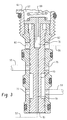
- FIG. 3 is an enlarged, fragmentary, axial cross-section, similar to FIG. 2, but illustrating an alternative embodiment of the pressure spike suppression valve of the present invention.
- Referring now to the drawings, which are not intended to limit the invention, FIG. 1 is a hydraulic schematic of a hydraulic control system for a mobile vehicle, including a hydrostatic ("full fluid-linked") power steering system of the type which can advantageously utilize the present invention, and which is illustrated schematically as including the present invention. The system includes a
fluid pump 11 which has its inlet connected to a system reservoir R. The outlet of thepump 11 is in fluid communication by means of aconduit 13 with the inlet of a load sensing priority flow control valve (LSPV), generally designated 15, of the type illustrated and described inU.S. Patent No. 3,455,210 , assigned to the assignee of the present invention and incorporated herein by reference. As is well known to those skilled in the art, the LSPV includes a controlled flow outlet port ("CF") which communicates by means of aconduit 17, through acheck valve 18, to a priority load circuit, and an excess flow outlet port ("EF") in fluid communication by means of aconduit 19 to some sort of auxiliary hydraulic load circuit (not shown herein). - In the subject embodiment, and by way of example only, the priority load circuit to which the
conduit 17 is connected is a steering control unit (SCU), generally designated 21, which includes aninlet port 23, areturn port 25, and a pair ofcontrol fluid ports 27 and 29. As is generally well known to those skilled in the power steering art, theSCU 21 includes controller valving, generally designated 31, by means of which the flow of pressurized fluid from theinlet port 23 may be communicated to either of thecontrol ports 27 or 29, depending upon the direction of steering input (represented schematically at "30") to the controller valving 31. Typically, the SCU 21 includes afluid meter 33, by means of which the fluid flowing through the controller valving 31 is measured (or "metered"). In addition, thefluid meter 33 provides, by means of a mechanical follow-up element 35, the appropriate follow-up movement to the controller valving 31 to return thevalving 31 to its neutral condition when thesteering input 30 to theSCU 21 ceases. It should be clear from the earlier description that the present invention is not limited to use in a hydraulic circuit in which the priority load circuit is hydrostatic power steering. - Referring still primarily to FIG. 1, the hydrostatic power steering system shown therein includes a pair of
steering cylinders fluid conduit 41, and each of which has an opposite fluid chamber in fluid communication with thecontrol port 29 by means of afluid conduit 43. Those skilled in the art will understand that the present invention is not limited to any particular arrangement ofcylinders SCU 21 is of the type which generates a load pressure representative of the hydraulic load on the actuator (steering cylinders 37 and 39). Therefore, theSCU 21 includes aload signal port 45 which receives a load signal from a location disposed downstream of a main variable flow control orifice (the schematic location of which is referenced at "46" in FIG. 1) defined by the controller valving 31 in a manner well known to those skilled in the art. The load signal is communicated from theload signal port 45 through aload signal line 47 to theLSPV 15, biasing the LSPV toward a position of greater flow in theconduit 17 and less flow in theconduit 19, all of which is also well known in the art. - Referring still primarily to FIG. 1, it may be seen that there is included, in the hydraulic control system, a pressure spike suppression valve, generally designated 51. The
valve 51 is in fluid communication with thefluid conduit 41 by means of aconduit 53, and is in fluid communication with thefluid conduit 43 by means of aconduit 55, such that the pressurespike suppression valve 51 is in a position to effectively "cross-port" thefluid conduits valve 51 is in communication with the mainsystem pressure conduit 17, communicating system pressure, by means of a systempressure signal line 57, and finally, is in fluid communication with theload signal line 47 by means of asignal line 59. - Referring now primarily to FIG. 2, but in conjunction with FIG. 1, there is illustrated an axial cross-section of one embodiment of the pressure
spike suppression valve 51 which comprises one aspect of the present invention. Thevalve 51 includes a main body which is externally threaded at its "lower" end in FIG. 2, such that thevalve 51 may be threadedly engaged within a bore defined by a manifold or some other structure or portion of the circuit. In other words, thevalve 51, in one preferred embodiment, is a cartridge valve, as that term is well understood in the valve art. In threaded engagement with an inner portion of themain body 61 issleeve valve 63, and slidably disposed therein is aspool valve 65. - The
main body 61 defines aspring chamber 67 and disposed therein is acompression spring 69. Themain body 61 is internally threaded, and in threaded engagement therewith is anadjustable spring seat 71 which would typically be adjusted at the time of the assembly of thevalve 51, or perhaps, would be finally adjusted upon final assembly and testing of the vehicle. In either case, the upper end in FIG. 2 of themain body 61 would have a threadedcap 73 in threaded engagement with themain body 61, thereby preventing any subsequent movement of thespring seat 71. - At the lower end (as viewed in FIG. 2) of the
compression spring 69 is aspring seat member 75 which includes a portion telescoped within acentral opening 76 in thespool valve 65, such that any movement of thespool valve 65 in an upward direction in FIG. 2 from the position shown can occur only in opposition to the biasing force of thespring 69. - Referring still to FIG. 2, the
sleeve valve 63 defines one or more (preferably, several)radial ports 77 which are in communication with the conduit 53 (and the fluid conduit 41), and severalradial ports 79 which are in fluid communication with the conduit 55 (and the fluid conduit 43). The lower end of thespool valve 65 defines a face (also referred to hereinafter and in the appended claims as a "chamber") 81 which is in communication with the systempressure signal line 57. Finally, thesleeve valve 63 defines severalradial ports 83 which are in fluid communication with thesignal line 59, connected to theload signal line 47. It should be noted in FIG. 2 that thespool valve 65 and thespring seat member 75 define additional fluid passages (including the central opening 76) whereby theradial ports 83 are able to communicate the load signal through thespring seat member 75 and into thespring chamber 67. For purposes of the appended claims, thespring chamber 67 also serves as a "load signal chamber", but it should be understood that the present invention is not limited to thechamber 67 being both the spring chamber and the load signal chamber, although such an arrangement may be more simple and compact, as shown herein in FIG. 2. - Therefore, the net force biasing the
spool valve 65 to its "first" condition (as shown in FIG. 2) is the sum of the force of thecompression spring 69 and the load signal pressure communicated by means of thesignal line 59. In opposition, and tending to bias thespool valve 65 in an upward direction, toward a "second" position is the system pressure as communicated from theconduit 17 by means of the systempressure signal line 57. It should be notedconduit 17 by means of the systempressure signal line 57. it should be noted that in the first position of thespool valve 65 shown in FIG. 2, thespool valve 65 blocks fluid communication between theradial ports 77 and theradial ports 79, thus blocking communication between theconduits fluid conduits - As is well known to those skilled in the art, in a typical hydraulic control circuit of the type shown in FIG. 1, there is a "normal" pressure differential between the system pressure in the
conduit 17 and the load pressure present in theload signal line 47. Thecompression spring 69 is selected such that the force exerted thereby on thespool valve 65 is substantially equivalent to the force which would be exerted on thespool valve 65 if thespool valve 65 were subjected to the "normal" pressure differential between system pressure and the load signal. Therefore, as long as the system is operating in its normal condition maintaining the designed pressure differential between system pressure and the load signal, the pressurespike suppression valve 51 will remain in the first position shown in FIG. 2, blocking any fluid communication between thefluid conduits - However, if the
SCU 21 is suddenly stopped or reversed, closing all of the various flow control orifices in thecontroller valving 31, including themain orifice 46, the system pressure in theconduit 17 will be trapped and will continue to rise, but the load signal present in theload signal line 47 will be drained to the system reservoir R by theSCU 21, in a manner which is now well known to those skilled in the art, thus quickly increasing the pressure differential betweenconduit 17 andload signal line 47. - Referring again to FIG. 2, this increasing pressure differential biases the
spool valve 65 upward toward the "second" position (actually, a range of positions), permitting fluid communication from theconduit 53 to the conduit 55 (or vice versa). This permitted communication between theconduits fluid conduits fluid conduits fluid conduits conduits fluid conduits valve 51 occurs in response to the increasing pressure differential between system pressure and the load signal, which may be viewed as a "leading" indicator of an impending or imminent pressure spike. - Referring now to FIG. 3, there is illustrated an alternative embodiment of the hydraulic control system and pressure
spike suppression valve 51 of FIGS. 1 and 2. In the embodiment represented in FIG. 3, all of the parts of the pressure spike suppression valve bear the same reference numerals as in the FIG. 2 embodiment because all of the parts may be substantially identical. The one difference is that thespool valve 65 defines an axially-extendingsignal passage 91, which communicates from the systempressure signal line 57 to thecentral opening 76. Therefore, in the embodiment of FIG. 3, there is a very small amount of fluid communicated from the systempressure signal line 57 through thesignal passage 91, and into both thecentral opening 76 and thesignal line 59. Those skilled in the load sensing art will recognize that this above-described small flow from thesignal line 57 into thesignal line 59 serves as a "dynamic" load signal, as opposed to the "static" type of load signal shown for the embodiment of FIGS. 1 and 2. - In connection with the use of the FIG. 3 embodiment of the
valve 51, the only change required in the circuit in FIG. 1 will be the location of thecheck valve 18. In the circuit of FIG. 1, with a static load signal system, thecheck valve 18 is disposed downstream of the junction of theconduit 17 and the systempressure signal line 57. If thevalve 51 of FIG. 2 is replaced by the dynamic load signal version of FIG. 3, thecheck valve 18 wouid be re-located to a position upstream of the junction of theconduit 17 and thesignal line 57, for reasons believed to be apparent to those skilled in the art. - The invention has been described in great detail in the foregoing specification, and it is believed that various alterations and modifications of the invention will become apparent to those skilled in the art from a reading and understanding of the specification. It is intended that all such alterations and modifications are included in the invention, insofar as they come within the scope of the appended claims.
Claims (5)
- A hydraulic control system including a source (11) of pressurized fluid having a load pressure responsive means (15) for varying the fluid delivery of said source; a fluid pressure operated actuator (37,39) defining a pair of actuator ports; and a main control valve (21) having an inlet (23) in fluid communication with said source (11), and a pair of control ports (27,29) in fluid communication with said actuator ports by means of first (41) and second (43) conduits; said main control valve (21) defining a main variable flow control orifice (46) which closes to prevent fluid flow through said main control valve when said main control valve is in a neutral condition (FIG. 1), and including means operable to generate a load pressure (45) representative of the hydraulic load on said actuator (37,39); and a pressure spike suppression valve (51) having first (53) and second (55) ports connected to said first (41) and second (43) conduits, respectively, said pressure spike suppression valve (51) including a valve member (65) moveable between a first position (FIG. 2) blocking fluid communication between said first (53) and second (55) ports, and a second position permitting fluid communication between said first and second ports; characterized by:(a) said pressure spike suppression valve (51) defining a spring chamber (67) including a compression spring (69) biasing said valve member (65) toward said first position (FIG. 2);(b) said pressure spike suppression valve defining a load signal passage (83) to communicate said load pressure (45) to a load signal chamber (67) also to bias said valve member (65) toward said first position (FIG. 2); and(c) said pressure spike suppression valve (51) defining a pressure chamber (81) in fluid communication with said source (11) of pressurized fluid, fluid pressure in said pressure chamber (81) biasing said valve member (65) toward said second position.
- A hydraulic control system as claimed in claim 1, characterized by said fluid pressure operated actuator comprising a steering cylinder (37), and said main control valve comprising a steering control unit (21) having said neutral condition (FIG. 1), and being operable, in response to manual input in first and second directions, to communicate pressurized fluid to said first (41) and second (43) conduits, respectively.
- A hydraulic control system as claimed in claim 1, characterized by said source of pressurized fluid comprising a pump (11) and a load sensing priority flow control valve (15) having its inlet in fluid communication with said pump (11) and a controlled flow outlet port (CF) in fluid communication with said main control valve (21).
- A hydraulic control system as claimed in claim 1, characterized by said pressure spike suppression valve (51) comprising a main body (61) adapted for threaded engagement with a threaded portion of other structure, whereby the pressure spike suppression valve comprises a cartridge valve.
- A hydraulic control system as claimed in claim 4, characterized by said pressure spike suppression valve (51) comprising a generally cylindrical sleeve valve (63), and said moveable valve member (65) comprises a spool valve (65) moveable within said sleeve valve (63) between said first (FIG. 2) and said second positions.
Applications Claiming Priority (1)
| Application Number | Priority Date | Filing Date | Title |
|---|---|---|---|
| US11/124,933 US7124579B1 (en) | 2005-05-09 | 2005-05-09 | Anti jerk valve |
Publications (3)
| Publication Number | Publication Date |
|---|---|
| EP1722109A2 true EP1722109A2 (en) | 2006-11-15 |
| EP1722109A3 EP1722109A3 (en) | 2007-09-12 |
| EP1722109B1 EP1722109B1 (en) | 2009-01-07 |
Family
ID=36764050
Family Applications (1)
| Application Number | Title | Priority Date | Filing Date |
|---|---|---|---|
| EP06009372A Expired - Fee Related EP1722109B1 (en) | 2005-05-09 | 2006-05-05 | Anti jerk valve |
Country Status (5)
| Country | Link |
|---|---|
| US (1) | US7124579B1 (en) |
| EP (1) | EP1722109B1 (en) |
| JP (1) | JP2006316998A (en) |
| CN (1) | CN1862031B (en) |
| DE (1) | DE602006004640D1 (en) |
Families Citing this family (13)
| Publication number | Priority date | Publication date | Assignee | Title |
|---|---|---|---|---|
| US7516757B2 (en) * | 2006-03-31 | 2009-04-14 | Eaton Corporation | Power beyond steering system |
| US7831352B2 (en) * | 2007-03-16 | 2010-11-09 | The Hartfiel Company | Hydraulic actuator control system |
| US7984785B2 (en) * | 2008-02-28 | 2011-07-26 | Eaton Corporation | Control valve assembly for electro-hydraulic steering system |
| US7931112B2 (en) * | 2008-05-02 | 2011-04-26 | Eaton Corporation | Isolation valve for a load-reaction steering system |
| US8684037B2 (en) * | 2009-08-05 | 2014-04-01 | Eaton Corportion | Proportional poppet valve with integral check valve |
| US8286652B2 (en) * | 2009-09-22 | 2012-10-16 | Eaton Corporation | Configurable active jerk control |
| US8770543B2 (en) | 2011-07-14 | 2014-07-08 | Eaton Corporation | Proportional poppet valve with integral check valves |
| CN102862603B (en) * | 2012-09-28 | 2015-12-09 | 中联重科股份有限公司 | Ratio convertible valve, ratio steering hydraulic loop, ratio steering swivel system and vehicle |
| US9878737B2 (en) * | 2015-02-20 | 2018-01-30 | Caterpillar Inc. | Hydraulic steering control system |
| CN104787111B (en) * | 2015-04-23 | 2018-04-24 | 圣邦集团有限公司 | A kind of control valve for steering |
| US10512204B1 (en) | 2016-07-22 | 2019-12-24 | Ag Leader Technology, Inc. | Heading measurement compensation for GNSS navigation |
| US10599151B1 (en) | 2017-01-13 | 2020-03-24 | Ag Leader Technology, Inc. | Transformer (modifier) design for controlling articulated vehicles smoothly |
| JP6996900B2 (en) | 2017-08-11 | 2022-01-17 | 株式会社小松製作所 | Work vehicle |
Citations (3)
| Publication number | Priority date | Publication date | Assignee | Title |
|---|---|---|---|---|
| US4040439A (en) * | 1976-03-29 | 1977-08-09 | Eaton Corporation | Cushion valve arrangement |
| US5025626A (en) * | 1989-08-31 | 1991-06-25 | Caterpillar Inc. | Cushioned swing circuit |
| EP1298256A2 (en) * | 2001-09-28 | 2003-04-02 | Kobelco Construction Machinery Co., Ltd. | Hydraulic system for suppression of vibrations of a working machine |
Family Cites Families (13)
| Publication number | Priority date | Publication date | Assignee | Title |
|---|---|---|---|---|
| US3330298A (en) * | 1965-08-05 | 1967-07-11 | Fawick Corp | Cushion valve arrangement |
| US4043419A (en) * | 1976-06-04 | 1977-08-23 | Eaton Corporation | Load sensing power steering system |
| US4663936A (en) * | 1984-06-07 | 1987-05-12 | Eaton Corporation | Load sensing priority system with bypass control |
| US4838314A (en) * | 1988-10-12 | 1989-06-13 | Deere & Company | Secondary hydraulic steering system |
| US5050696A (en) * | 1988-10-20 | 1991-09-24 | Deere & Company | Secondary hydraulic steering system |
| DE69014312T2 (en) * | 1989-01-13 | 1995-04-06 | Hitachi Construction Machinery | Hydraulic system for the boom cylinder of a construction machine. |
| US5179835A (en) * | 1991-08-15 | 1993-01-19 | Eaton Corporation | Brake valve for use in load sensing hydraulic system |
| JPH0565903A (en) * | 1991-09-04 | 1993-03-19 | Hitachi Constr Mach Co Ltd | Hydraulic circuit for attachment |
| CN2158823Y (en) * | 1993-06-07 | 1994-03-16 | 中国农业机械化科学研究院 | Pressure-controlled automatic compensation type load-sensing hydraulic rotating apparatus |
| JPH11115780A (en) * | 1997-10-15 | 1999-04-27 | Komatsu Ltd | Displacement control method of steering pump for work vehicle and its device |
| US6474064B1 (en) * | 2000-09-14 | 2002-11-05 | Case Corporation | Hydraulic system and method for regulating pressure equalization to suppress oscillation in heavy equipment |
| JP2002206504A (en) * | 2001-01-10 | 2002-07-26 | Hitachi Constr Mach Co Ltd | Hydraulic motor driving device |
| CN2560535Y (en) * | 2002-01-18 | 2003-07-16 | 济宁伊顿液压有限公司 | Load-sensing hydraulic-steering priority valve |
-
2005
- 2005-05-09 US US11/124,933 patent/US7124579B1/en not_active Expired - Fee Related
-
2006
- 2006-05-05 DE DE602006004640T patent/DE602006004640D1/en active Active
- 2006-05-05 EP EP06009372A patent/EP1722109B1/en not_active Expired - Fee Related
- 2006-05-09 CN CN2006100916969A patent/CN1862031B/en not_active Expired - Fee Related
- 2006-05-09 JP JP2006130582A patent/JP2006316998A/en active Pending
Patent Citations (3)
| Publication number | Priority date | Publication date | Assignee | Title |
|---|---|---|---|---|
| US4040439A (en) * | 1976-03-29 | 1977-08-09 | Eaton Corporation | Cushion valve arrangement |
| US5025626A (en) * | 1989-08-31 | 1991-06-25 | Caterpillar Inc. | Cushioned swing circuit |
| EP1298256A2 (en) * | 2001-09-28 | 2003-04-02 | Kobelco Construction Machinery Co., Ltd. | Hydraulic system for suppression of vibrations of a working machine |
Also Published As
| Publication number | Publication date |
|---|---|
| JP2006316998A (en) | 2006-11-24 |
| US20060248883A1 (en) | 2006-11-09 |
| EP1722109A3 (en) | 2007-09-12 |
| DE602006004640D1 (en) | 2009-02-26 |
| CN1862031A (en) | 2006-11-15 |
| US7124579B1 (en) | 2006-10-24 |
| CN1862031B (en) | 2010-09-29 |
| EP1722109B1 (en) | 2009-01-07 |
Similar Documents
| Publication | Publication Date | Title |
|---|---|---|
| EP1722109B1 (en) | Anti jerk valve | |
| US9550521B2 (en) | Hydraulic steering arrangement | |
| US4663936A (en) | Load sensing priority system with bypass control | |
| EP3078571B1 (en) | Hydraulic steering system | |
| EP3093213B1 (en) | Hydraulic steering system | |
| US4011721A (en) | Fluid control system utilizing pressure drop valve | |
| US10611402B2 (en) | Hydraulic steering unit | |
| US4253382A (en) | Steering valve assembly for steering and brake system | |
| US7185730B2 (en) | Hydraulic steering arrangement | |
| US7866151B2 (en) | Anti-saturation valve assembly for load sensing hydraulic system | |
| US10953915B2 (en) | Hydraulic steering unit | |
| US5279121A (en) | Flow control valve with pilot operation and pressure compensation | |
| US10730548B2 (en) | Hydraulic steering unit | |
| JPH0742708A (en) | Control method of liquid-operated motor and liquid-operated valve therefor | |
| US10953914B2 (en) | Hydraulic steering unit | |
| US6782698B2 (en) | Steering control unit with low null band load sensing boost |
Legal Events
| Date | Code | Title | Description |
|---|---|---|---|
| PUAI | Public reference made under article 153(3) epc to a published international application that has entered the european phase |
Free format text: ORIGINAL CODE: 0009012 |
|
| AK | Designated contracting states |
Kind code of ref document: A2 Designated state(s): AT BE BG CH CY CZ DE DK EE ES FI FR GB GR HU IE IS IT LI LT LU LV MC NL PL PT RO SE SI SK TR |
|
| AX | Request for extension of the european patent |
Extension state: AL BA HR MK YU |
|
| PUAL | Search report despatched |
Free format text: ORIGINAL CODE: 0009013 |
|
| AK | Designated contracting states |
Kind code of ref document: A3 Designated state(s): AT BE BG CH CY CZ DE DK EE ES FI FR GB GR HU IE IS IT LI LT LU LV MC NL PL PT RO SE SI SK TR |
|
| AX | Request for extension of the european patent |
Extension state: AL BA HR MK YU |
|
| 17P | Request for examination filed |
Effective date: 20080306 |
|
| AKX | Designation fees paid |
Designated state(s): DE FR GB IT SE |
|
| GRAP | Despatch of communication of intention to grant a patent |
Free format text: ORIGINAL CODE: EPIDOSNIGR1 |
|
| GRAS | Grant fee paid |
Free format text: ORIGINAL CODE: EPIDOSNIGR3 |
|
| GRAA | (expected) grant |
Free format text: ORIGINAL CODE: 0009210 |
|
| AK | Designated contracting states |
Kind code of ref document: B1 Designated state(s): DE FR GB IT SE |
|
| REG | Reference to a national code |
Ref country code: GB Ref legal event code: FG4D |
|
| REF | Corresponds to: |
Ref document number: 602006004640 Country of ref document: DE Date of ref document: 20090226 Kind code of ref document: P |
|
| REG | Reference to a national code |
Ref country code: SE Ref legal event code: TRGR |
|
| PLBE | No opposition filed within time limit |
Free format text: ORIGINAL CODE: 0009261 |
|
| STAA | Information on the status of an ep patent application or granted ep patent |
Free format text: STATUS: NO OPPOSITION FILED WITHIN TIME LIMIT |
|
| 26N | No opposition filed |
Effective date: 20091008 |
|
| REG | Reference to a national code |
Ref country code: FR Ref legal event code: PLFP Year of fee payment: 11 |
|
| PGFP | Annual fee paid to national office [announced via postgrant information from national office to epo] |
Ref country code: DE Payment date: 20160524 Year of fee payment: 11 Ref country code: GB Payment date: 20160426 Year of fee payment: 11 |
|
| PGFP | Annual fee paid to national office [announced via postgrant information from national office to epo] |
Ref country code: IT Payment date: 20160518 Year of fee payment: 11 Ref country code: SE Payment date: 20160506 Year of fee payment: 11 Ref country code: FR Payment date: 20160428 Year of fee payment: 11 |
|
| REG | Reference to a national code |
Ref country code: DE Ref legal event code: R119 Ref document number: 602006004640 Country of ref document: DE |
|
| REG | Reference to a national code |
Ref country code: SE Ref legal event code: EUG |
|
| GBPC | Gb: european patent ceased through non-payment of renewal fee |
Effective date: 20170505 |
|
| PG25 | Lapsed in a contracting state [announced via postgrant information from national office to epo] |
Ref country code: SE Free format text: LAPSE BECAUSE OF NON-PAYMENT OF DUE FEES Effective date: 20170506 |
|
| REG | Reference to a national code |
Ref country code: FR Ref legal event code: ST Effective date: 20180131 |
|
| PG25 | Lapsed in a contracting state [announced via postgrant information from national office to epo] |
Ref country code: GB Free format text: LAPSE BECAUSE OF NON-PAYMENT OF DUE FEES Effective date: 20170505 Ref country code: DE Free format text: LAPSE BECAUSE OF NON-PAYMENT OF DUE FEES Effective date: 20171201 |
|
| PG25 | Lapsed in a contracting state [announced via postgrant information from national office to epo] |
Ref country code: IT Free format text: LAPSE BECAUSE OF NON-PAYMENT OF DUE FEES Effective date: 20170505 Ref country code: FR Free format text: LAPSE BECAUSE OF NON-PAYMENT OF DUE FEES Effective date: 20170531 |