EP1722047A2 - Vehicle inside door handle - Google Patents
Vehicle inside door handle Download PDFInfo
- Publication number
- EP1722047A2 EP1722047A2 EP06009306A EP06009306A EP1722047A2 EP 1722047 A2 EP1722047 A2 EP 1722047A2 EP 06009306 A EP06009306 A EP 06009306A EP 06009306 A EP06009306 A EP 06009306A EP 1722047 A2 EP1722047 A2 EP 1722047A2
- Authority
- EP
- European Patent Office
- Prior art keywords
- handle
- bumper
- cap
- pivot
- mating member
- Prior art date
- Legal status (The legal status is an assumption and is not a legal conclusion. Google has not performed a legal analysis and makes no representation as to the accuracy of the status listed.)
- Granted
Links
Images


Classifications
-
- E—FIXED CONSTRUCTIONS
- E05—LOCKS; KEYS; WINDOW OR DOOR FITTINGS; SAFES
- E05B—LOCKS; ACCESSORIES THEREFOR; HANDCUFFS
- E05B85/00—Details of vehicle locks not provided for in groups E05B77/00 - E05B83/00
- E05B85/10—Handles
- E05B85/12—Inner door handles
- E05B85/13—Inner door handles with a locking knob forming part of the inside door handle unit
-
- E—FIXED CONSTRUCTIONS
- E05—LOCKS; KEYS; WINDOW OR DOOR FITTINGS; SAFES
- E05B—LOCKS; ACCESSORIES THEREFOR; HANDCUFFS
- E05B17/00—Accessories in connection with locks
- E05B17/0004—Lock assembling or manufacturing
-
- E—FIXED CONSTRUCTIONS
- E05—LOCKS; KEYS; WINDOW OR DOOR FITTINGS; SAFES
- E05B—LOCKS; ACCESSORIES THEREFOR; HANDCUFFS
- E05B77/00—Vehicle locks characterised by special functions or purposes
- E05B77/02—Vehicle locks characterised by special functions or purposes for accident situations
- E05B77/04—Preventing unwanted lock actuation, e.g. unlatching, at the moment of collision
- E05B77/06—Preventing unwanted lock actuation, e.g. unlatching, at the moment of collision by means of inertial forces
-
- E—FIXED CONSTRUCTIONS
- E05—LOCKS; KEYS; WINDOW OR DOOR FITTINGS; SAFES
- E05B—LOCKS; ACCESSORIES THEREFOR; HANDCUFFS
- E05B77/00—Vehicle locks characterised by special functions or purposes
- E05B77/42—Means for damping the movement of lock parts, e.g. slowing down the return movement of a handle
-
- E—FIXED CONSTRUCTIONS
- E05—LOCKS; KEYS; WINDOW OR DOOR FITTINGS; SAFES
- E05B—LOCKS; ACCESSORIES THEREFOR; HANDCUFFS
- E05B85/00—Details of vehicle locks not provided for in groups E05B77/00 - E05B83/00
- E05B85/10—Handles
- E05B85/12—Inner door handles
-
- B—PERFORMING OPERATIONS; TRANSPORTING
- B29—WORKING OF PLASTICS; WORKING OF SUBSTANCES IN A PLASTIC STATE IN GENERAL
- B29C—SHAPING OR JOINING OF PLASTICS; SHAPING OF MATERIAL IN A PLASTIC STATE, NOT OTHERWISE PROVIDED FOR; AFTER-TREATMENT OF THE SHAPED PRODUCTS, e.g. REPAIRING
- B29C45/00—Injection moulding, i.e. forcing the required volume of moulding material through a nozzle into a closed mould; Apparatus therefor
- B29C45/14—Injection moulding, i.e. forcing the required volume of moulding material through a nozzle into a closed mould; Apparatus therefor incorporating preformed parts or layers, e.g. injection moulding around inserts or for coating articles
- B29C45/1418—Injection moulding, i.e. forcing the required volume of moulding material through a nozzle into a closed mould; Apparatus therefor incorporating preformed parts or layers, e.g. injection moulding around inserts or for coating articles the inserts being deformed or preformed, e.g. by the injection pressure
-
- B—PERFORMING OPERATIONS; TRANSPORTING
- B29—WORKING OF PLASTICS; WORKING OF SUBSTANCES IN A PLASTIC STATE IN GENERAL
- B29C—SHAPING OR JOINING OF PLASTICS; SHAPING OF MATERIAL IN A PLASTIC STATE, NOT OTHERWISE PROVIDED FOR; AFTER-TREATMENT OF THE SHAPED PRODUCTS, e.g. REPAIRING
- B29C45/00—Injection moulding, i.e. forcing the required volume of moulding material through a nozzle into a closed mould; Apparatus therefor
- B29C45/14—Injection moulding, i.e. forcing the required volume of moulding material through a nozzle into a closed mould; Apparatus therefor incorporating preformed parts or layers, e.g. injection moulding around inserts or for coating articles
- B29C45/14688—Coating articles provided with a decoration
-
- E—FIXED CONSTRUCTIONS
- E05—LOCKS; KEYS; WINDOW OR DOOR FITTINGS; SAFES
- E05B—LOCKS; ACCESSORIES THEREFOR; HANDCUFFS
- E05B1/00—Knobs or handles for wings; Knobs, handles, or press buttons for locks or latches on wings
- E05B1/04—Knobs or handles for wings; Knobs, handles, or press buttons for locks or latches on wings with inner rigid member and outer cover or covers
-
- Y—GENERAL TAGGING OF NEW TECHNOLOGICAL DEVELOPMENTS; GENERAL TAGGING OF CROSS-SECTIONAL TECHNOLOGIES SPANNING OVER SEVERAL SECTIONS OF THE IPC; TECHNICAL SUBJECTS COVERED BY FORMER USPC CROSS-REFERENCE ART COLLECTIONS [XRACs] AND DIGESTS
- Y10—TECHNICAL SUBJECTS COVERED BY FORMER USPC
- Y10S—TECHNICAL SUBJECTS COVERED BY FORMER USPC CROSS-REFERENCE ART COLLECTIONS [XRACs] AND DIGESTS
- Y10S292/00—Closure fasteners
- Y10S292/31—Lever operator, flush
-
- Y—GENERAL TAGGING OF NEW TECHNOLOGICAL DEVELOPMENTS; GENERAL TAGGING OF CROSS-SECTIONAL TECHNOLOGIES SPANNING OVER SEVERAL SECTIONS OF THE IPC; TECHNICAL SUBJECTS COVERED BY FORMER USPC CROSS-REFERENCE ART COLLECTIONS [XRACs] AND DIGESTS
- Y10—TECHNICAL SUBJECTS COVERED BY FORMER USPC
- Y10T—TECHNICAL SUBJECTS COVERED BY FORMER US CLASSIFICATION
- Y10T292/00—Closure fasteners
- Y10T292/57—Operators with knobs or handles
Definitions
- Embodiments of the present invention generally relate to door handles, and more particularly, to a door handle assembly that may be used as a vehicle inside door handle.
- various vehicles include specifically designed interior door handles.
- one automobile may have a first handle style, while another may have a different style.
- each different type of door handle is separately manufactured. That is, the first handle style is manufactured with a first mold, die, or the like, while a second style is manufactured with a second mold, die, or the like. Separately manufacturing each door handle with different tools increases manufacturing time and costs.
- in-mold decorating is well known. However, it is generally known that inlays are bondable only to certain types of resins. In the past, in-molding door handles was not common practice because the resins necessary for bonding to the inlay were not strong enough with respect to vehicle door handle specifications.
- Embodiments of the present invention provide a door handle assembly that may include a handle pivot housing, a main handle, a bumper, and a plurality of caps configured to be interchangeably secured to the main handle.
- the handle pivot housing includes a bumper wall integrally formed with handle engaging-walls defining a handle pivot cavity therebetween.
- the bumper wall includes at least one mating member, such as a slot, tab, latch, clasp, barb, snap, hook, or the like.
- At least one of the handle-engaging walls includes an integrally formed boss extending into the handle pivot cavity.
- the main handle may include an arm integrally formed with a pivot joint defining a pivot axis, and a counterweight.
- the pivot joint rotatably secures to the boss, and the counterweight and the arm are positioned on opposite sides of the pivot axis in order to move the center of gravity closer to the pivot axis.
- the bumper may include a mating member, so that the bumper secures to the bumper wall proximate the counterweight through a mating between corresponding mating members.
- the bumper provides a cushioned barrier with respect to the main handle.
- the caps are configured to be snapably, latchably, or otherwise removably secured to the main handle.
- Each cap is formed of a different material than the main handle. Further, each cap may differ in size, shape structure, material, texture, or color with respect to other caps.
- At least one of the handle pivot housing and the main handle may also include, or cooperate to provide, at least one positive stop that limits movement of the main handle within the handle pivot housing.
- the door handle assembly may also include a lock knob that maintains the pivot joint in rotatable securement with respect to the boss.
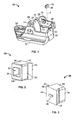
- Figure 1 illustrates an isometric rear view of a handle pivot housing according to an embodiment of the present invention.
- Figure 2 illustrates an isometric front view of a bumper according to an embodiment of the present invention.
- Figure 3 illustrates an isometric rear view of a bumper according to an embodiment of the present invention.
- Figure 4 illustrates an isometric front view of a handle pivot housing according to an embodiment of the present invention.
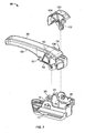
- Figure 5 illustrates an isometric exploded view of a handle subassembly according to an embodiment of the present invention.
- Figure 6 illustrates a partial lateral view of a handle subassembly according to an embodiment of the present invention.
- Figure 7 illustrates an isometric exploded view of a handle assembly according to an embodiment of the present invention.
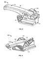
- Figure 8 illustrates an isometric view of a handle assembly according to an embodiment of the present invention.
- Figure 9 illustrates an isometric view of a handle assembly according to an embodiment of the present invention.
- FIG. 1 illustrates an isometric rear view of a handle pivot housing 10 according to an embodiment of the present invention.
- the housing 10 includes a lower support wall 12 integrally formed with upstanding handle-engaging walls 14 and 16, an upstanding lock wall 18, and a rear, or bumper, wall 20.
- the lower support walls 12 includes a fastener through-hole 22 and other features that are configured to secure the handle base 10 to a fixed structure, such as an interior of a door.
- a handle pivot cavity 24 is defined between the two handle-engaging walls 14 and 16, while a lock knob cavity 26 is defined between the handle-engaging wall 16 and the lock wall 18.
- the rear wall 20 includes a channel 28 configured to receive and retain a bumper 30.
- a slot, opening or depression 32 is formed through the rear wall 20 and extends into the channel 28. The slot 32 is configured to snapably secure a reciprocal structure 46 on the bumper 28, which is urged into the channel in the direction of A.
- FIG. 2 illustrates an isometric front view of the bumper 30.
- the bumper 30 may be formed of rubber, plastic, or other such materials, and includes lateral walls 34 integrally formed with top and bottom walls 36 and 38, respectively.
- An inner cavity 40 may be defined between the lateral walls 34 and the top and bottom walls 36 and 38, respectively.
- the lateral, top, and bottom walls 34, 36, and 38, respectively are integrally formed with a channel-engaging base 42 having lateral flanges 44.
- Figure 3 illustrates an isometric rear view of the bumper 30.
- a protuberance, such as a tab, 46 outwardly extends from a rear surface 48 of the channel-engaging base 42.
- Figure 4 illustrates an isometric front view of the handle pivot housing 10.
- the bumper 30 is urged into the channel 28 in the direction of A such that the lateral flanges 44 are slidably received in notches 50 formed in the rear wall 20.
- the bumper 30 continues to slide through the channel 28 in the direction of A, until the tab 46 encounters the slot 32 of the rear wall, thereby snapably securing the bumper 30 within the channel 28.
- the bumper 30 provides a cushioned barrier for a handle subassembly (discussed below), and particularly a counterweight (discussed below) while at rest and through rotation of the handle subassembly within the handle pivot cavity 24.
- the bumper 30 may, alternatively, have a slot formed therethrough, while the rear wall 20 includes a tab extending into the handle pivot cavity 24.
- the bumper 30 may be integrally formed with the rear wall 20.
- FIG. 5 illustrates an isometric exploded view of a handle subassembly 52.
- the handle subassembly 52 includes a main handle 54, a cap 56, and a counterweight 58.
- the main handle 54 includes an arm 60 extending from a pivot joint 62.
- the arm 60 may be grasped by a user in order to rotate the main handle 54 when it is rotatably secured within the handle pivot housing 10.
- the pivot joint 62 includes a boss opening 64 configured to rotatably retain a boss extending from the handle-engaging wall 14 of the handle pivot housing 10 (shown, e.g., in Figures 1-4).
- the main handle 54 includes one or more protuberances 65 extending from one or both lateral surfaces 66.
- the cap 56 may be chrome plated, painted, molded in different colors, decorated with graphics according to any number of different methods, or, preferably, in-mold decorated.
- the cap 56 includes lateral walls 72 integrally formed with a top wall 74 and blunted end 76. Slots 78 may be formed through portions of at least one of the lateral walls 72.
- the cap 56 is configured to snapably, latchably, or otherwise removably secure to the main handle 54 by way of the slots 78 securely engaging the protuberances 65 of the main handle 54.
- the blunted end 76 of the cap 56 is positioned around a portion of the distal end 82 of the main handle 54, and the cap 56 is pivoted in the direction of arc B about the distal end 82, until the slots 78 snapably secure around the protuberances 65, and the proximal lip 84 of the cap 56 snapably secures around a corresponding edge 86 of the main handle 54.
- the blunted end 76 of the cap 56 may snapably, latchably, or otherwise engage around a corresponding structure located at the distal end 82 of the main handle 54.
- the protuberances 65 of the main handle 54 may be slots, while the slots 78 of the cap 56 may be protuberances.
- corresponding structure on the cap and the handle may be utilized for a snap-fit or other latching arrangements.
- caps 56 having different ornamentation and styles may be used with the handle subassembly 52.
- Each cap 56 may include slots, tabs, and the like that allow it to secure to the main handle 54.
- main handle 54 may be manufactured, and a wide variety of caps 56 may be used with that type of main handle 54.
- the main handle 54 may be manufactured from a different material than the cap 56, because the main handle 54 is separate and distinct from the cap 56.
- the main handle 54 may be formed of a relatively strong material, such as plastic or glass-filled nylon with mineral additives; while the cap may be made with a different material suitable for decoration, such as a compounded thermoplastic, like ABS or similar materials.
- the handle subassembly 52 meets desired vehicle door handle specifications because of the strength of the underlying main handle 54.
- the counterweight 58 is urged into a counterweight housing 88 extending from a proximal end of the pivot joint 62 in the direction of C.
- the counterweight 58 may be made of any suitable material, such as, for example, a zinc alloy, aluminum, or the like.
- the handle subassembly 52 is configured to receive the counterweight 58 through the housing 88, support, end, or the like, in order to provide an anti-opening assembly.
- a fin 94 extends upwardly from the counterweight 58. The counterweight 58 is moved into the housing 88 until an upper tab 90 snapably secures into a corresponding slot 92 of the housing 88.
- the counterweight 58 and housing 88 may also include additional features that assist in securing the counterweight into the housing 88.
- the counterweight 58 may include a slot, while the housing 88 includes a corresponding tab.
- the counterweight 58 and the housing 88 may be integrally formed as a single unit.
- the counterweight 58 may be secured to the handle subassembly in a variety of ways. For example, the counterweight 58 may be snapped onto the housing 88 from above or below, and/or the counterweight 58 may be bonded or latched to the housing 88.
- Figure 6 illustrates a partial lateral view of the handle subassembly 52.
- the fin 94 abuts the lip 84 of the cap 56, thereby securing the cap 56 into position.
- the main handle 54 and cap 56 are precluded from rotating in the direction of arc D with respect to the counterweight 58 and housing 88.
- the lock created by the fin 94 abutting the lip 84 ensures that the cap 56 remains on the main handle 54 during thermo-cycle testing, material thermo-expansion and contraction and operation.
- FIG. 7 illustrates an isometric exploded view of a handle assembly 96.
- the pivot joint 62 of the handle subassembly 52 is positioned in the handle pivot cavity 24 of the handle pivot housing 10 such that the boss opening 64 securely and rotatably engages the boss 98 extending from the handle engaging wall 14.
- the boss 98 is integrally molded with the handle pivot housing 10.
- a lock knob 100 is then secured within the lock knob cavity 26 of the handle pivot housing 10.
- the lock knob 100 includes a lateral wall 102 integrally formed with an arcuate upper wall 104.
- the arcuate upper wall 104 overlays a portion 106 of the main handle 54 or cap 56.
- the handle subassembly 52 may pivot about the boss 98.
- the lock knob 100 can assist to ensure that the handle subassembly 52 remains rotatably secured to the boss 98. That is, the lock knob 100 can act as a barrier past which the handle subassembly 52, particularly the portion 106 covered by the upper arcuate wall 104, cannot slide past.
- Figure 8 illustrates an isometric view of the handle assembly 96.
- the counterweight 58 is positioned on the opposite side of the pivot axis (that is, the boss 98) from the arm 60. The position of the counterweight 58, therefore, moves the center of gravity of the handle subassembly 52 closer to the pivot axis. Additionally, the cap 56 may be removed and another cap, having a different design, ornamentation, surface, or formed of a different material, may be secured to the main handle 54.
- the handle assembly 96 may include a plurality of positive stops.
- the pivot housing 10 may include a protruding block 107 (shown, for example, in Figure 4) configured to abut a curved lower tip 109 (shown, for example, in Figure 5) of the handle assembly 52.
- the handle pivot housing 10 may include a ramped surface 111 (shown, for example, in Figure 1) that is steeper than adjoining surfaces.
- the inside edge 86 (shown, for example, in Figure 5) may be rotated into abutment with the ramped surface 111, which serves as a dwell for the inside edge 86.
- the handle assembly 96 may include more or less positive stops or dwells than those shown and described.
- FIG 9 illustrates an isometric view of a handle assembly 110 according to an embodiment of the present invention.
- the handle assembly 110 includes a handle pivot housing 112 that pivotally supports a handle subassembly 114.
- a lock knob 116 ensures that the handle subassembly 114 remains pivotally secured within the handle pivot housing 112.
- a counterweight 118 on the opposite side of the pivot axis than the arm 120 of the handle subassembly 114 provides a center of gravity closer to the pivot axis than the distal end of the handle subassembly 114.
- the cap 122 does not include slots formed through lateral surfaces.
- the cap 122 may include interior ridges or ledges that snapably secure to reciprocal structures formed in the main handle (covered by cap 122).
- the counterweight 118 may be bulkier and heavier than the counterweight 58 (shown, for example, in Figure 5).
- the counterweight 118 may include a downwardly extending rib that mates with a slot (not shown) formed in a counterweight housing or support so that the counterweight 118 may be secured above the counterweight housing or support.
- embodiments of the present invention provide a door handle assembly that remains closed during an impact, despite the overall weight of the door handle. Because embodiments of the present invention provide a door handle assembly having a center of gravity that is closer to the pivot axis, the door handle assembly is less susceptible to accidentally swinging open during an impact, as compared to previous door handles.
- embodiments of the prevent invention provide a door handle assembly that includes components, such as the handle pivot housing and the main handle, that may be universally used with all door handles.
- one ornamental handle design may use a first cap with the main handle, while another ornamental design may use a second cap with the main handle.
- all portions of the door handle assembly, with the exception of the caps, may be manufactured using the same tools and processes.
- embodiments of the present invention provide a system that may be decorative, yet robust and easy to manufacture.
- an in-mold decorative cap for a door handle assembly.
- An inlay decorative film is place into a mold.
- a resin material is shot into the mold so that the film is joined to the resin material through the molding process.
- a chemical bond is created between the film and resin material to create a thermo-formed cap.
- the cap is then secured to the main handle to provide a handle subassembly.
- the handle subassembly is then assembled to the housing.
Landscapes
- Engineering & Computer Science (AREA)
- Manufacturing & Machinery (AREA)
- Lock And Its Accessories (AREA)
Abstract
Description
- This application relates to and claims priority benefits from
U.S. Provisional Patent Application 60/680,921 - Embodiments of the present invention generally relate to door handles, and more particularly, to a door handle assembly that may be used as a vehicle inside door handle.
- Conventional vehicle inside door handles are susceptible to swinging open during a crash or violent maneuver. The heavier a handle is, the further away its center of gravity is from its pivot axis. The further away the center of gravity is from the pivot axis, the easier it is for the door handle to swing open during an impact. As door handles become larger and heavier, the possibility of the door handles swinging open during an impact increases. Thus, a need exists for a door handle that remains closed during an impact, despite the overall weight of the door handle.
- Additionally, various vehicles include specifically designed interior door handles. For example, one automobile may have a first handle style, while another may have a different style. Typically, each different type of door handle is separately manufactured. That is, the first handle style is manufactured with a first mold, die, or the like, while a second style is manufactured with a second mold, die, or the like. Separately manufacturing each door handle with different tools increases manufacturing time and costs.
- In-mold decorating is well known. However, it is generally known that inlays are bondable only to certain types of resins. In the past, in-molding door handles was not common practice because the resins necessary for bonding to the inlay were not strong enough with respect to vehicle door handle specifications.
- Thus, a need exists for a system that includes components that may be universally used with all door handles. Further, a need exists for a strong door handle that may be decorative, yet robust and easy to manufacture.
- Embodiments of the present invention provide a door handle assembly that may include a handle pivot housing, a main handle, a bumper, and a plurality of caps configured to be interchangeably secured to the main handle. The handle pivot housing includes a bumper wall integrally formed with handle engaging-walls defining a handle pivot cavity therebetween. The bumper wall includes at least one mating member, such as a slot, tab, latch, clasp, barb, snap, hook, or the like. At least one of the handle-engaging walls includes an integrally formed boss extending into the handle pivot cavity.
- The main handle may include an arm integrally formed with a pivot joint defining a pivot axis, and a counterweight. The pivot joint rotatably secures to the boss, and the counterweight and the arm are positioned on opposite sides of the pivot axis in order to move the center of gravity closer to the pivot axis.
- The bumper may include a mating member, so that the bumper secures to the bumper wall proximate the counterweight through a mating between corresponding mating members. The bumper provides a cushioned barrier with respect to the main handle.
- The caps are configured to be snapably, latchably, or otherwise removably secured to the main handle. Each cap is formed of a different material than the main handle. Further, each cap may differ in size, shape structure, material, texture, or color with respect to other caps.
- At least one of the handle pivot housing and the main handle may also include, or cooperate to provide, at least one positive stop that limits movement of the main handle within the handle pivot housing. The door handle assembly may also include a lock knob that maintains the pivot joint in rotatable securement with respect to the boss.
- Figure 1 illustrates an isometric rear view of a handle pivot housing according to an embodiment of the present invention.
- Figure 2 illustrates an isometric front view of a bumper according to an embodiment of the present invention.
- Figure 3 illustrates an isometric rear view of a bumper according to an embodiment of the present invention.
- Figure 4 illustrates an isometric front view of a handle pivot housing according to an embodiment of the present invention.
- Figure 5 illustrates an isometric exploded view of a handle subassembly according to an embodiment of the present invention.
- Figure 6 illustrates a partial lateral view of a handle subassembly according to an embodiment of the present invention.
- Figure 7 illustrates an isometric exploded view of a handle assembly according to an embodiment of the present invention.
- Figure 8 illustrates an isometric view of a handle assembly according to an embodiment of the present invention.
- Figure 9 illustrates an isometric view of a handle assembly according to an embodiment of the present invention.
- Before the embodiments of the invention are explained in detail, it is to be understood that the invention is not limited in its application to the details of construction and the arrangement of the components set forth in the following description or illustrated in the drawings. The invention is capable of other embodiments and of being practiced or being carried out in various ways. Also, it is to be understood that the phraseology and terminology used herein are for the purpose of description and should not be regarded as limiting. The use of "including" and "comprising" and variations thereof is meant to encompass the items listed thereafter and equivalents thereof as well as additional items and equivalents thereof.
- Figure I illustrates an isometric rear view of a
handle pivot housing 10 according to an embodiment of the present invention. Thehousing 10 includes alower support wall 12 integrally formed with upstanding handle-engaging walls upstanding lock wall 18, and a rear, or bumper,wall 20. Thelower support walls 12 includes a fastener through-hole 22 and other features that are configured to secure thehandle base 10 to a fixed structure, such as an interior of a door. Ahandle pivot cavity 24 is defined between the two handle-engaging walls lock knob cavity 26 is defined between the handle-engaging wall 16 and thelock wall 18. Therear wall 20 includes achannel 28 configured to receive and retain abumper 30. A slot, opening ordepression 32 is formed through therear wall 20 and extends into thechannel 28. Theslot 32 is configured to snapably secure areciprocal structure 46 on thebumper 28, which is urged into the channel in the direction of A. - Figure 2 illustrates an isometric front view of the
bumper 30. Thebumper 30 may be formed of rubber, plastic, or other such materials, and includeslateral walls 34 integrally formed with top andbottom walls inner cavity 40 may be defined between thelateral walls 34 and the top andbottom walls bottom walls engaging base 42 havinglateral flanges 44. - Figure 3 illustrates an isometric rear view of the
bumper 30. A protuberance, such as a tab, 46 outwardly extends from arear surface 48 of the channel-engaging base 42. - Figure 4 illustrates an isometric front view of the
handle pivot housing 10. Referring to Figures 1-4, thebumper 30 is urged into thechannel 28 in the direction of A such that thelateral flanges 44 are slidably received innotches 50 formed in therear wall 20. Thebumper 30 continues to slide through thechannel 28 in the direction of A, until thetab 46 encounters theslot 32 of the rear wall, thereby snapably securing thebumper 30 within thechannel 28. Thebumper 30 provides a cushioned barrier for a handle subassembly (discussed below), and particularly a counterweight (discussed below) while at rest and through rotation of the handle subassembly within thehandle pivot cavity 24. While thebumper 30 is shown having thetab 46, and theslot 32 is formed through therear wall 20, thebumper 30 may, alternatively, have a slot formed therethrough, while therear wall 20 includes a tab extending into thehandle pivot cavity 24. Optionally, thebumper 30 may be integrally formed with therear wall 20. - Figure 5 illustrates an isometric exploded view of a
handle subassembly 52. Thehandle subassembly 52 includes amain handle 54, acap 56, and acounterweight 58. Themain handle 54 includes anarm 60 extending from a pivot joint 62. Thearm 60 may be grasped by a user in order to rotate themain handle 54 when it is rotatably secured within thehandle pivot housing 10. The pivot joint 62 includes aboss opening 64 configured to rotatably retain a boss extending from the handle-engagingwall 14 of the handle pivot housing 10 (shown, e.g., in Figures 1-4). Additionally, themain handle 54 includes one ormore protuberances 65 extending from one or both lateral surfaces 66. - The
cap 56 may be chrome plated, painted, molded in different colors, decorated with graphics according to any number of different methods, or, preferably, in-mold decorated. Thecap 56 includeslateral walls 72 integrally formed with atop wall 74 and bluntedend 76.Slots 78 may be formed through portions of at least one of thelateral walls 72. Thecap 56 is configured to snapably, latchably, or otherwise removably secure to themain handle 54 by way of theslots 78 securely engaging theprotuberances 65 of themain handle 54. In particular, the bluntedend 76 of thecap 56 is positioned around a portion of thedistal end 82 of themain handle 54, and thecap 56 is pivoted in the direction of arc B about thedistal end 82, until theslots 78 snapably secure around theprotuberances 65, and theproximal lip 84 of thecap 56 snapably secures around a correspondingedge 86 of themain handle 54. Additionally, the bluntedend 76 of thecap 56 may snapably, latchably, or otherwise engage around a corresponding structure located at thedistal end 82 of themain handle 54. Alternatively, theprotuberances 65 of themain handle 54 may be slots, while theslots 78 of thecap 56 may be protuberances. In other embodiments, corresponding structure on the cap and the handle may be utilized for a snap-fit or other latching arrangements. - A variety of
caps 56 having different ornamentation and styles may be used with thehandle subassembly 52. Eachcap 56 may include slots, tabs, and the like that allow it to secure to themain handle 54. Thus, one type ofmain handle 54 may be manufactured, and a wide variety ofcaps 56 may be used with that type ofmain handle 54. - The
main handle 54 may be manufactured from a different material than thecap 56, because themain handle 54 is separate and distinct from thecap 56. For example, themain handle 54 may be formed of a relatively strong material, such as plastic or glass-filled nylon with mineral additives; while the cap may be made with a different material suitable for decoration, such as a compounded thermoplastic, like ABS or similar materials. Despite the nature of thecap 56, thehandle subassembly 52 meets desired vehicle door handle specifications because of the strength of the underlyingmain handle 54. - Once the
cap 56 is secured to themain handle 54, thecounterweight 58 is urged into acounterweight housing 88 extending from a proximal end of the pivot joint 62 in the direction of C. Thecounterweight 58 may be made of any suitable material, such as, for example, a zinc alloy, aluminum, or the like. Thehandle subassembly 52 is configured to receive thecounterweight 58 through thehousing 88, support, end, or the like, in order to provide an anti-opening assembly. Afin 94 extends upwardly from thecounterweight 58. Thecounterweight 58 is moved into thehousing 88 until anupper tab 90 snapably secures into a corresponding slot 92 of thehousing 88. Thecounterweight 58 andhousing 88 may also include additional features that assist in securing the counterweight into thehousing 88. Optionally, thecounterweight 58 may include a slot, while thehousing 88 includes a corresponding tab. Alternatively, thecounterweight 58 and thehousing 88 may be integrally formed as a single unit. Also, thecounterweight 58 may be secured to the handle subassembly in a variety of ways. For example, thecounterweight 58 may be snapped onto thehousing 88 from above or below, and/or thecounterweight 58 may be bonded or latched to thehousing 88. - Figure 6 illustrates a partial lateral view of the
handle subassembly 52. As shown in Figure 6, once thecounterweight 58 is secured within thehousing 88, thefin 94 abuts thelip 84 of thecap 56, thereby securing thecap 56 into position. As such, themain handle 54 andcap 56 are precluded from rotating in the direction of arc D with respect to thecounterweight 58 andhousing 88. The lock created by thefin 94 abutting thelip 84 ensures that thecap 56 remains on themain handle 54 during thermo-cycle testing, material thermo-expansion and contraction and operation. - Figure 7 illustrates an isometric exploded view of a
handle assembly 96. In order to assemble thehandle assembly 96, thepivot joint 62 of thehandle subassembly 52 is positioned in thehandle pivot cavity 24 of thehandle pivot housing 10 such that theboss opening 64 securely and rotatably engages theboss 98 extending from thehandle engaging wall 14. Theboss 98 is integrally molded with thehandle pivot housing 10. Alock knob 100 is then secured within thelock knob cavity 26 of thehandle pivot housing 10. Thelock knob 100 includes alateral wall 102 integrally formed with an arcuateupper wall 104. The arcuateupper wall 104 overlays aportion 106 of themain handle 54 orcap 56. - After the
handle assembly 96 is assembled, thehandle subassembly 52 may pivot about theboss 98. Thelock knob 100 can assist to ensure that thehandle subassembly 52 remains rotatably secured to theboss 98. That is, thelock knob 100 can act as a barrier past which thehandle subassembly 52, particularly theportion 106 covered by the upperarcuate wall 104, cannot slide past. - Figure 8 illustrates an isometric view of the
handle assembly 96. As shown in Figures 5-8, thecounterweight 58 is positioned on the opposite side of the pivot axis (that is, the boss 98) from thearm 60. The position of thecounterweight 58, therefore, moves the center of gravity of thehandle subassembly 52 closer to the pivot axis. Additionally, thecap 56 may be removed and another cap, having a different design, ornamentation, surface, or formed of a different material, may be secured to themain handle 54. - Referring to Figures 4-8, the
handle assembly 96 may include a plurality of positive stops. For example, thepivot housing 10 may include a protruding block 107 (shown, for example, in Figure 4) configured to abut a curved lower tip 109 (shown, for example, in Figure 5) of thehandle assembly 52. When thehandle subassembly 52 is rotated relative to thehandle pivot housing 10, the curvedlower tip 109 is rotated into abutment with theblock 107, thereby halting further rotation. Additionally, thehandle pivot housing 10 may include a ramped surface 111 (shown, for example, in Figure 1) that is steeper than adjoining surfaces. When thehandle subassembly 52 is rotated relative to thehandle pivot housing 10, the inside edge 86 (shown, for example, in Figure 5) may be rotated into abutment with the rampedsurface 111, which serves as a dwell for theinside edge 86. Thehandle assembly 96 may include more or less positive stops or dwells than those shown and described. - Figure 9 illustrates an isometric view of a
handle assembly 110 according to an embodiment of the present invention. Thehandle assembly 110 includes ahandle pivot housing 112 that pivotally supports ahandle subassembly 114. Alock knob 116 ensures that thehandle subassembly 114 remains pivotally secured within thehandle pivot housing 112. Acounterweight 118 on the opposite side of the pivot axis than thearm 120 of thehandle subassembly 114 provides a center of gravity closer to the pivot axis than the distal end of thehandle subassembly 114. As shown in Figure 9, thecap 122 does not include slots formed through lateral surfaces. Instead, thecap 122 may include interior ridges or ledges that snapably secure to reciprocal structures formed in the main handle (covered by cap 122). Additionally, thecounterweight 118 may be bulkier and heavier than the counterweight 58 (shown, for example, in Figure 5). Also, thecounterweight 118 may include a downwardly extending rib that mates with a slot (not shown) formed in a counterweight housing or support so that thecounterweight 118 may be secured above the counterweight housing or support. - Thus, embodiments of the present invention provide a door handle assembly that remains closed during an impact, despite the overall weight of the door handle. Because embodiments of the present invention provide a door handle assembly having a center of gravity that is closer to the pivot axis, the door handle assembly is less susceptible to accidentally swinging open during an impact, as compared to previous door handles.
- Additionally, embodiments of the prevent invention provide a door handle assembly that includes components, such as the handle pivot housing and the main handle, that may be universally used with all door handles. For example, one ornamental handle design may use a first cap with the main handle, while another ornamental design may use a second cap with the main handle. Overall, all portions of the door handle assembly, with the exception of the caps, may be manufactured using the same tools and processes. Moreover, embodiments of the present invention provide a system that may be decorative, yet robust and easy to manufacture.
- According to one embodiment of the present invention, an in-mold decorative cap is provided for a door handle assembly. An inlay decorative film is place into a mold. A resin material is shot into the mold so that the film is joined to the resin material through the molding process. A chemical bond is created between the film and resin material to create a thermo-formed cap. The cap is then secured to the main handle to provide a handle subassembly. The handle subassembly is then assembled to the housing. In this way, various decorative caps can be utilized in accordance with the present invention.
- While terms such as front, lateral, rear, upper, lower, and the like may be used to describe various components of embodiments of the present invention, it is understood that such terms are relative and are merely to describe components in relation to the drawings. The orientations, however, may be changed, such that the front is rear or lateral, while upper may be lower, and the like.
- Variations and modifications of the foregoing are within the scope of the present invention. It is understood that the invention disclosed and defined herein extends to all alternative combinations of two or more of the individual features mentioned or evident from the text and/or drawings. All of these different combinations constitute various alternative aspects of the present invention. The embodiments described herein explain the best modes known for practicing the invention and will enable others skilled in the art to utilize the invention. The claims are to be construed to include alternative embodiments to the extent permitted by the prior art.
- Various features of the invention are set forth in the following claims.
Claims (26)
- A door handle assembly comprising:a handle pivot housing comprising handle engaging-walls defining a handle pivot cavity therebetween, at least one of said handle-engaging walls comprising an integrally formed boss extending into said handle pivot cavity;a main handle comprising an arm integrally formed with a pivot joint defining a pivot axis, said pivot joint rotatably securing to said boss; anda cap secured to said main handle, said cap being made of a different material than said main handle.
- The door handle assembly of claim 1, wherein said cap is snapably secured to said main handle.
- The door handle assembly of claim 1 or 2, further comprising a counterweight, said counterweight and said arm being positioned on opposite sides of said pivot axis.
- The door handle assembly of claim 3, wherein said counterweight further comprises a fin that abuts said cap so as to secure said cap onto said main handle.
- The door handle assembly of claim 4, further comprising a bumper comprising a first mating member, said handle pivot housing further comprising a bumper wall integrally formed with said handle-engaging walls, said bumper wall comprising a second mating member, said bumper securing to said bumper wall through said first mating member mating with said second mating member, wherein said bumper provides a cushioned barrier with respect to said main handle, and wherein said bumper is secured to said bumper wall proximate said counterweight.
- The door handle assembly of anyone of the preceding claims, further comprising a bumper comprising a first mating member, said handle pivot housing further comprising a bumper wall integrally formed with said handle-engaging walls, said bumper wall comprising a second mating member, said bumper securing to said bumper wall through said first mating member mating with said second mating member, wherein said bumper provides a cushioned barrier with respect to said main handle.
- The door handle assembly of claim 6, wherein said first mating member is one of a tab and slot, and wherein said second mating member is an opposite one of said tab and said slot.
- The door handle assembly of anyone of the preceding claims, wherein at least one of said handle pivot housing and said main handle further comprises at least one positive stop that limits movement of said main handle within said handle pivot housing.
- The door handle assembly of anyone of the preceding claims, further comprising a lock knob that assists in maintaining said pivot joint in rotatable securement with respect to said boss.
- A door handle assembly comprising:a handle pivot housing comprising handle engaging-walls defining a handle pivot cavity therebetween, at least one of said handle-engaging walls comprising an integrally formed boss extending into said handle pivot cavity;a main handle comprising an arm integrally formed with a pivot joint defining a pivot axis, said pivot joint rotatably securing to said boss; anda first cap secured to said main handle, said first cap being formed of a different material than said main handle, said first cap being an in-mold decorated cap formed as a molded cap with an inlay decorative piece.
- The door handle assembly of claim 10, wherein said first cap is snapably secured to said main handle.
- The door handle assembly of claim 11, wherein said first cap includes a first end positioned around a portion of a first end of said main handle, and wherein said first cap further includes a second end having a lip positioned around a second end of said main handle.
- The door handle assembly of claim 11 or 12, further comprising a second cap configured to be secured to said main handle, such that said first cap and said second cap are interchangeable with respect to said main handle, and wherein said first and second caps differ in at least one of size, shape, structure, material, texture, and color.
- The door handle assembly of anyone of claims 10 to 13, further comprising a counterweight, said counterweight and said arm being positioned on opposite sides of said pivot axis.
- The door handle assembly of claim 13 or 14, wherein said counterweight further comprises a fin that abuts said cap so as to secure said cap onto said main handle.
- The door handle assembly of claim 15, further comprising a bumper comprising a first mating member, said handle pivot housing further comprising a bumper wall integrally formed with said handle-engaging walls, said bumper wall comprising a second mating member, said bumper securing to said bumper wall through said first mating member mating with said second mating member, wherein said bumper provides a cushioned barrier with respect to said main handle, and wherein said bumper is secured to said bumper wall proximate said counterweight.
- The door handle assembly of anyone of claims 10 to 16, further comprising a bumper comprising a first mating member, said handle pivot housing further comprising a bumper wall integrally formed with said handle-engaging walls, said bumper wall comprising a second mating member, said bumper securing to said bumper wall through said first mating member mating with said second mating member, wherein said bumper provides a cushioned barrier with respect to said main handle.
- The door handle assembly of claim 17, wherein said first mating member is one of a tab and slot, and wherein said second mating member is an opposite one of said tab and said slot.
- The door handle assembly of anyone of claims 10 to 18, wherein at least one of said handle pivot housing and said main handle further comprises at least one positive stop that limits movement of said main handle within said handle pivot housing.
- The door handle assembly of anyone of claims 10 to 19, further comprising a lock knob that assists in maintaining said pivot joint in rotatable securement with respect to said boss.
- A method of making a door handle assembly, said method comprising the steps of:placing an inlay decorative film into a mold;molding a cap in the mold about the inlay thereby creating a thermo-formed cap;securing the cap to a handle to provide a handle subassembly; andplacing the handle subassembly in a handle pivot housing.
- The method of claim 21, wherein the cap is snap-fitted to the handle.
- The method of claim 21 or 22, wherein the handle subassembly includes a counterweight housing, and the method further comprises placing a counterweight in the counterweight housing.
- The method of claim 23, wherein the counterweight is adapted to abut the cap to further secure the cap to the handle.
- The method of claim 23 or 24, wherein the handle pivot housing includes a bumper wall having a first mating member, and the method further comprises securing a bumper with a second mating member on the bumper wall through mating engagement of the first mating member and the second mating member.
- The method of claim 25, wherein the bumper is secured to the bumper wall proximate said counterweight.
Priority Applications (1)
| Application Number | Priority Date | Filing Date | Title |
|---|---|---|---|
| EP07116479A EP1860260B1 (en) | 2005-05-13 | 2006-05-05 | Door Handle Assembly |
Applications Claiming Priority (2)
| Application Number | Priority Date | Filing Date | Title |
|---|---|---|---|
| US68092105P | 2005-05-13 | 2005-05-13 | |
| US11/397,374 US7527307B2 (en) | 2005-05-13 | 2006-04-04 | Door handle assembly |
Related Child Applications (1)
| Application Number | Title | Priority Date | Filing Date |
|---|---|---|---|
| EP07116479A Division EP1860260B1 (en) | 2005-05-13 | 2006-05-05 | Door Handle Assembly |
Publications (3)
| Publication Number | Publication Date |
|---|---|
| EP1722047A2 true EP1722047A2 (en) | 2006-11-15 |
| EP1722047A3 EP1722047A3 (en) | 2007-06-13 |
| EP1722047B1 EP1722047B1 (en) | 2009-04-01 |
Family
ID=36979798
Family Applications (1)
| Application Number | Title | Priority Date | Filing Date |
|---|---|---|---|
| EP20060009306 Expired - Lifetime EP1722047B1 (en) | 2005-05-13 | 2006-05-05 | Door handle assembly |
Country Status (6)
| Country | Link |
|---|---|
| US (2) | US7527307B2 (en) |
| EP (1) | EP1722047B1 (en) |
| AT (2) | ATE427399T1 (en) |
| DE (2) | DE602006005982D1 (en) |
| ES (2) | ES2324112T3 (en) |
| PT (1) | PT1722047E (en) |
Cited By (2)
| Publication number | Priority date | Publication date | Assignee | Title |
|---|---|---|---|---|
| WO2012027265A1 (en) * | 2010-08-23 | 2012-03-01 | Illinois Tool Works Inc. | Snap set door handle and lock knob assembly |
| WO2017211500A1 (en) * | 2016-06-10 | 2017-12-14 | Huf Hülsbeck & Fürst Gmbh & Co. Kg | Door handle module for a motor vehicle |
Families Citing this family (16)
| Publication number | Priority date | Publication date | Assignee | Title |
|---|---|---|---|---|
| EP1783305B1 (en) * | 2004-08-05 | 2015-04-22 | Aisin Seiki Kabushiki Kaisha | Door handle device |
| JP4882370B2 (en) * | 2005-12-27 | 2012-02-22 | アイシン精機株式会社 | Vehicle door handle |
| US20080197582A1 (en) * | 2007-02-19 | 2008-08-21 | Botten Eric M | Outer door handle gasket for automotive vehicles |
| JP5661372B2 (en) * | 2010-08-19 | 2015-01-28 | 株式会社アルファ | Vehicle door handle device |
| US8864193B2 (en) * | 2011-08-10 | 2014-10-21 | Honda Motor Co., Ltd. | Vehicle door inner handle cable connection |
| EP2712986B1 (en) * | 2012-09-07 | 2020-03-11 | U-Shin Italia S.p.A. | Vehicle panel handle lever |
| JP6082613B2 (en) * | 2013-02-06 | 2017-02-15 | 本田技研工業株式会社 | Vehicle door handle device |
| US8732910B1 (en) * | 2013-02-28 | 2014-05-27 | General Electric Companmy | Appliance handle assembly |
| DE102014107861A1 (en) * | 2014-06-04 | 2015-12-17 | Illinois Tool Works Inc. | Door handle for an automobile and method of manufacturing a door handle |
| KR101628499B1 (en) * | 2014-10-17 | 2016-06-21 | 현대자동차주식회사 | Structure for preventing door opening at side impact and method for preventing door opening at side impact |
| DE102016200589A1 (en) | 2015-02-05 | 2016-08-11 | Ford Global Technologies, Llc | The door handle assembly |
| JP6504867B2 (en) * | 2015-03-16 | 2019-04-24 | 株式会社アルファ | Vehicle door handle device |
| CN108086820B (en) * | 2017-12-18 | 2023-02-17 | 神通科技集团股份有限公司 | Door handle structure |
| DE102018108614A1 (en) * | 2018-04-11 | 2019-10-17 | Illinois Tool Works Inc. | An interior door handle assembly of a vehicle and method of manufacturing an interior door handle assembly |
| EP3916180B1 (en) * | 2020-05-29 | 2023-07-05 | Illinois Tool Works Inc. | Actuating element, in particular handle element, of an inner door handle arrangement of a vehicle and method for manufacturing such actuating element |
| JP7770117B2 (en) * | 2021-06-04 | 2025-11-14 | 株式会社アルファ | Door handle device for vehicle |
Family Cites Families (25)
| Publication number | Priority date | Publication date | Assignee | Title |
|---|---|---|---|---|
| GB2203481A (en) * | 1987-04-16 | 1988-10-19 | Schlegel | Lockable handle |
| JP2514583Y2 (en) * | 1990-03-27 | 1996-10-23 | アイシン精機株式会社 | Inside door handle for vehicle |
| FR2695673B1 (en) | 1992-09-11 | 1994-10-28 | Peugeot | External door control, especially for motor vehicles. |
| US5493756A (en) * | 1994-12-12 | 1996-02-27 | Silvatrim Associates | Refrigerator door handle |
| US5895081A (en) * | 1995-04-24 | 1999-04-20 | Aisin Seiki Kabushiki Kaisha | Inside door handle assembly for vehicles |
| US5794994A (en) * | 1995-08-09 | 1998-08-18 | Ohi Seisakusho Co., Ltd. | Inside door handle unit for automotive vehicle |
| WO1999019585A1 (en) * | 1997-10-14 | 1999-04-22 | Huf Hülsbeck & Fürst Gmbh & Co. Kg | Closing device, in particular for motor vehicles |
| JPH11336379A (en) * | 1998-05-22 | 1999-12-07 | Alpha Corp | Inside handle unit structure of a car |
| DE19833263A1 (en) | 1998-07-23 | 2000-01-27 | Wilke Heinrich Hewi Gmbh | Door and window handles as well as sanitary elements |
| US6152501A (en) * | 1999-05-25 | 2000-11-28 | Nyx, Inc. | Glove box door handle and latch assembly |
| GB2353245A (en) | 1999-08-20 | 2001-02-21 | Rover Group | A moulding technique |
| JP4314698B2 (en) * | 1999-11-10 | 2009-08-19 | トヨタ紡織株式会社 | Assist grip mounting structure |
| US6612630B1 (en) * | 2000-10-13 | 2003-09-02 | Adac Plastics Inc. | Motor vehicle door handle assembly with split housing |
| JP3794291B2 (en) * | 2001-06-29 | 2006-07-05 | スズキ株式会社 | Door handle assembly structure |
| DE10232244B4 (en) * | 2002-07-17 | 2005-03-10 | Huf Huelsbeck & Fuerst Gmbh | Locking system for a door, flap o. The like., Especially for vehicles |
| JP4015568B2 (en) * | 2003-01-29 | 2007-11-28 | アイシン精機株式会社 | Outside handle device and connector structure thereof |
| US7270359B2 (en) * | 2003-07-07 | 2007-09-18 | Johnson Controls Technology Company | Assist handle assembly with accessories |
| US7066506B2 (en) * | 2003-09-30 | 2006-06-27 | Key Plastics, Llc | System for preventing inadvertent locking of a vehicle door |
| CN1878922A (en) * | 2003-11-03 | 2006-12-13 | 关键塑料有限公司 | Exterior door handle with minimum surface intrusion |
| US6988752B2 (en) * | 2003-12-18 | 2006-01-24 | Illinois Tool Works Inc. | Pinless inside door handle assembly |
| US7036857B2 (en) * | 2003-12-22 | 2006-05-02 | Nissan Technical Center North America, Inc. | Vehicle inside door handle assembly |
| JP4509585B2 (en) * | 2004-01-26 | 2010-07-21 | 株式会社ニフコ | Damper and door handle with this damper |
| FR2869059B1 (en) * | 2004-04-14 | 2006-06-30 | Fabi Automobile Soc Par Action | MECHANISM FOR OPENING / CLOSING OF AUTOMOTIVE VEHICLE DOOR |
| US7284776B2 (en) * | 2004-08-04 | 2007-10-23 | Adac Plastics, Inc. | Vehicular door handle included secondary latch |
| JP4453477B2 (en) * | 2004-08-05 | 2010-04-21 | アイシン精機株式会社 | Door handle device |
-
2006
- 2006-04-04 US US11/397,374 patent/US7527307B2/en not_active Expired - Lifetime
- 2006-05-05 DE DE200660005982 patent/DE602006005982D1/en not_active Expired - Lifetime
- 2006-05-05 EP EP20060009306 patent/EP1722047B1/en not_active Expired - Lifetime
- 2006-05-05 ES ES06009306T patent/ES2324112T3/en not_active Expired - Lifetime
- 2006-05-05 AT AT06009306T patent/ATE427399T1/en not_active IP Right Cessation
- 2006-05-05 DE DE200660008120 patent/DE602006008120D1/en not_active Expired - Lifetime
- 2006-05-05 ES ES07116479T patent/ES2331031T3/en not_active Expired - Lifetime
- 2006-05-05 PT PT06009306T patent/PT1722047E/en unknown
- 2006-05-05 AT AT07116479T patent/ATE438006T1/en not_active IP Right Cessation
- 2006-08-23 US US11/508,622 patent/US7520543B2/en not_active Expired - Lifetime
Cited By (5)
| Publication number | Priority date | Publication date | Assignee | Title |
|---|---|---|---|---|
| WO2012027265A1 (en) * | 2010-08-23 | 2012-03-01 | Illinois Tool Works Inc. | Snap set door handle and lock knob assembly |
| CN103097633A (en) * | 2010-08-23 | 2013-05-08 | 伊利诺斯工具制品有限公司 | Snap set door handle and lock knob assembly |
| CN103097633B (en) * | 2010-08-23 | 2016-08-03 | 伊利诺斯工具制品有限公司 | Clamping apparatus door handle and locking knot button component |
| US10352072B2 (en) | 2010-08-23 | 2019-07-16 | Illinois Tool Works Inc. | Snap set door handle and lock knob assembly |
| WO2017211500A1 (en) * | 2016-06-10 | 2017-12-14 | Huf Hülsbeck & Fürst Gmbh & Co. Kg | Door handle module for a motor vehicle |
Also Published As
| Publication number | Publication date |
|---|---|
| DE602006005982D1 (en) | 2009-05-14 |
| EP1722047A3 (en) | 2007-06-13 |
| PT1722047E (en) | 2009-06-19 |
| DE602006008120D1 (en) | 2009-09-10 |
| US20060284430A1 (en) | 2006-12-21 |
| ES2331031T3 (en) | 2009-12-18 |
| EP1722047B1 (en) | 2009-04-01 |
| US20060255600A1 (en) | 2006-11-16 |
| US7520543B2 (en) | 2009-04-21 |
| ATE427399T1 (en) | 2009-04-15 |
| ATE438006T1 (en) | 2009-08-15 |
| US7527307B2 (en) | 2009-05-05 |
| ES2324112T3 (en) | 2009-07-30 |
Similar Documents
| Publication | Publication Date | Title |
|---|---|---|
| EP1722047B1 (en) | Door handle assembly | |
| KR20010093150A (en) | Outer door handle, especially for motor vehicles, with a bow-type handle and with a pressure-actuated element integrated therein | |
| JPWO2001056834A1 (en) | Pocket structure in interior trim | |
| US10435922B2 (en) | Vehicle handle bezel assembly having a movable cover | |
| GB2497874A (en) | Vehicle door inside handle device | |
| US20150329066A1 (en) | Tailgate liner assembly and method for vehicle tailgate | |
| CN211722695U (en) | Vertical hook | |
| US20200010027A1 (en) | Snap-on cover for vehicle door handle | |
| GB2423064A (en) | Storage pocket on vehicle door | |
| EP1860260A1 (en) | Door Handle Assembly | |
| US8701814B2 (en) | Concealment apparatus for ignition interlock devices | |
| EP0802288B1 (en) | An integrated handle in the body, particularly the doors and/or the hatches, of a motor vehicle | |
| JP4398041B2 (en) | Armrest for automobile and manufacturing method thereof | |
| CN210454654U (en) | Automobile glove box and automobile | |
| US7111772B2 (en) | Decorative mailbox | |
| CN209008362U (en) | A license plate trim assembly | |
| US8201859B2 (en) | Door handle assembly | |
| US11098507B2 (en) | Door handle assembly with retention feature | |
| KR100428385B1 (en) | Structure for mounting a tray cover of luggage room | |
| US7234752B2 (en) | Molded visor with integral vanity frame | |
| CN222611006U (en) | B-pillar handle and vehicle with same | |
| JP4020375B2 (en) | Door grip mounting structure | |
| JPH09317265A (en) | Escussion mounting structure for door inside handle | |
| JP2006027317A (en) | Cover plate mounting structure | |
| CN201105699Y (en) | Sedan car trunk rear decorative plate |
Legal Events
| Date | Code | Title | Description |
|---|---|---|---|
| PUAI | Public reference made under article 153(3) epc to a published international application that has entered the european phase |
Free format text: ORIGINAL CODE: 0009012 |
|
| 17P | Request for examination filed |
Effective date: 20060505 |
|
| AK | Designated contracting states |
Kind code of ref document: A2 Designated state(s): AT BE BG CH CY CZ DE DK EE ES FI FR GB GR HU IE IS IT LI LT LU LV MC NL PL PT RO SE SI SK TR |
|
| AX | Request for extension of the european patent |
Extension state: AL BA HR MK YU |
|
| PUAL | Search report despatched |
Free format text: ORIGINAL CODE: 0009013 |
|
| AK | Designated contracting states |
Kind code of ref document: A3 Designated state(s): AT BE BG CH CY CZ DE DK EE ES FI FR GB GR HU IE IS IT LI LT LU LV MC NL PL PT RO SE SI SK TR |
|
| AX | Request for extension of the european patent |
Extension state: AL BA HR MK YU |
|
| 17Q | First examination report despatched |
Effective date: 20070808 |
|
| AKX | Designation fees paid |
Designated state(s): AT BE BG CH CY CZ DE DK EE ES FI FR GB GR HU IE IS IT LI LT LU LV MC NL PL PT RO SE SI SK TR |
|
| RIN1 | Information on inventor provided before grant (corrected) |
Inventor name: CALLISTER, TODD Inventor name: BONADONA, DAVID Inventor name: MARCINIAK, DOUGLAS Inventor name: PURDY, WILLIAM A. Inventor name: BELCHINE, WALTER Inventor name: LEE, JOEL R. |
|
| GRAP | Despatch of communication of intention to grant a patent |
Free format text: ORIGINAL CODE: EPIDOSNIGR1 |
|
| RTI1 | Title (correction) |
Free format text: DOOR HANDLE ASSEMBLY |
|
| GRAS | Grant fee paid |
Free format text: ORIGINAL CODE: EPIDOSNIGR3 |
|
| GRAA | (expected) grant |
Free format text: ORIGINAL CODE: 0009210 |
|
| AK | Designated contracting states |
Kind code of ref document: B1 Designated state(s): AT BE BG CH CY CZ DE DK EE ES FI FR GB GR HU IE IS IT LI LT LU LV MC NL PL PT RO SE SI SK TR |
|
| REG | Reference to a national code |
Ref country code: GB Ref legal event code: FG4D |
|
| REG | Reference to a national code |
Ref country code: CH Ref legal event code: EP |
|
| REG | Reference to a national code |
Ref country code: IE Ref legal event code: FG4D |
|
| REF | Corresponds to: |
Ref document number: 602006005982 Country of ref document: DE Date of ref document: 20090514 Kind code of ref document: P |
|
| REG | Reference to a national code |
Ref country code: PT Ref legal event code: SC4A Free format text: AVAILABILITY OF NATIONAL TRANSLATION Effective date: 20090609 |
|
| REG | Reference to a national code |
Ref country code: ES Ref legal event code: FG2A Ref document number: 2324112 Country of ref document: ES Kind code of ref document: T3 |
|
| PG25 | Lapsed in a contracting state [announced via postgrant information from national office to epo] |
Ref country code: SI Free format text: LAPSE BECAUSE OF FAILURE TO SUBMIT A TRANSLATION OF THE DESCRIPTION OR TO PAY THE FEE WITHIN THE PRESCRIBED TIME-LIMIT Effective date: 20090401 |
|
| PG25 | Lapsed in a contracting state [announced via postgrant information from national office to epo] |
Ref country code: AT Free format text: LAPSE BECAUSE OF FAILURE TO SUBMIT A TRANSLATION OF THE DESCRIPTION OR TO PAY THE FEE WITHIN THE PRESCRIBED TIME-LIMIT Effective date: 20090401 Ref country code: LT Free format text: LAPSE BECAUSE OF FAILURE TO SUBMIT A TRANSLATION OF THE DESCRIPTION OR TO PAY THE FEE WITHIN THE PRESCRIBED TIME-LIMIT Effective date: 20090401 Ref country code: FI Free format text: LAPSE BECAUSE OF FAILURE TO SUBMIT A TRANSLATION OF THE DESCRIPTION OR TO PAY THE FEE WITHIN THE PRESCRIBED TIME-LIMIT Effective date: 20090401 Ref country code: EE Free format text: LAPSE BECAUSE OF FAILURE TO SUBMIT A TRANSLATION OF THE DESCRIPTION OR TO PAY THE FEE WITHIN THE PRESCRIBED TIME-LIMIT Effective date: 20090401 |
|
| PG25 | Lapsed in a contracting state [announced via postgrant information from national office to epo] |
Ref country code: IS Free format text: LAPSE BECAUSE OF FAILURE TO SUBMIT A TRANSLATION OF THE DESCRIPTION OR TO PAY THE FEE WITHIN THE PRESCRIBED TIME-LIMIT Effective date: 20090801 Ref country code: SE Free format text: LAPSE BECAUSE OF FAILURE TO SUBMIT A TRANSLATION OF THE DESCRIPTION OR TO PAY THE FEE WITHIN THE PRESCRIBED TIME-LIMIT Effective date: 20090701 Ref country code: PL Free format text: LAPSE BECAUSE OF FAILURE TO SUBMIT A TRANSLATION OF THE DESCRIPTION OR TO PAY THE FEE WITHIN THE PRESCRIBED TIME-LIMIT Effective date: 20090401 Ref country code: LV Free format text: LAPSE BECAUSE OF FAILURE TO SUBMIT A TRANSLATION OF THE DESCRIPTION OR TO PAY THE FEE WITHIN THE PRESCRIBED TIME-LIMIT Effective date: 20090401 |
|
| PG25 | Lapsed in a contracting state [announced via postgrant information from national office to epo] |
Ref country code: MC Free format text: LAPSE BECAUSE OF NON-PAYMENT OF DUE FEES Effective date: 20090531 |
|
| PG25 | Lapsed in a contracting state [announced via postgrant information from national office to epo] |
Ref country code: CZ Free format text: LAPSE BECAUSE OF FAILURE TO SUBMIT A TRANSLATION OF THE DESCRIPTION OR TO PAY THE FEE WITHIN THE PRESCRIBED TIME-LIMIT Effective date: 20090401 Ref country code: DK Free format text: LAPSE BECAUSE OF FAILURE TO SUBMIT A TRANSLATION OF THE DESCRIPTION OR TO PAY THE FEE WITHIN THE PRESCRIBED TIME-LIMIT Effective date: 20090401 Ref country code: RO Free format text: LAPSE BECAUSE OF FAILURE TO SUBMIT A TRANSLATION OF THE DESCRIPTION OR TO PAY THE FEE WITHIN THE PRESCRIBED TIME-LIMIT Effective date: 20090401 |
|
| PLBE | No opposition filed within time limit |
Free format text: ORIGINAL CODE: 0009261 |
|
| STAA | Information on the status of an ep patent application or granted ep patent |
Free format text: STATUS: NO OPPOSITION FILED WITHIN TIME LIMIT |
|
| PG25 | Lapsed in a contracting state [announced via postgrant information from national office to epo] |
Ref country code: BE Free format text: LAPSE BECAUSE OF FAILURE TO SUBMIT A TRANSLATION OF THE DESCRIPTION OR TO PAY THE FEE WITHIN THE PRESCRIBED TIME-LIMIT Effective date: 20090401 Ref country code: SK Free format text: LAPSE BECAUSE OF FAILURE TO SUBMIT A TRANSLATION OF THE DESCRIPTION OR TO PAY THE FEE WITHIN THE PRESCRIBED TIME-LIMIT Effective date: 20090401 |
|
| 26N | No opposition filed |
Effective date: 20100105 |
|
| PG25 | Lapsed in a contracting state [announced via postgrant information from national office to epo] |
Ref country code: BG Free format text: LAPSE BECAUSE OF FAILURE TO SUBMIT A TRANSLATION OF THE DESCRIPTION OR TO PAY THE FEE WITHIN THE PRESCRIBED TIME-LIMIT Effective date: 20090701 |
|
| PG25 | Lapsed in a contracting state [announced via postgrant information from national office to epo] |
Ref country code: IE Free format text: LAPSE BECAUSE OF NON-PAYMENT OF DUE FEES Effective date: 20090505 |
|
| PG25 | Lapsed in a contracting state [announced via postgrant information from national office to epo] |
Ref country code: GR Free format text: LAPSE BECAUSE OF FAILURE TO SUBMIT A TRANSLATION OF THE DESCRIPTION OR TO PAY THE FEE WITHIN THE PRESCRIBED TIME-LIMIT Effective date: 20090702 |
|
| REG | Reference to a national code |
Ref country code: CH Ref legal event code: PL |
|
| PG25 | Lapsed in a contracting state [announced via postgrant information from national office to epo] |
Ref country code: CH Free format text: LAPSE BECAUSE OF NON-PAYMENT OF DUE FEES Effective date: 20100531 Ref country code: LI Free format text: LAPSE BECAUSE OF NON-PAYMENT OF DUE FEES Effective date: 20100531 |
|
| PG25 | Lapsed in a contracting state [announced via postgrant information from national office to epo] |
Ref country code: LU Free format text: LAPSE BECAUSE OF NON-PAYMENT OF DUE FEES Effective date: 20090505 |
|
| PG25 | Lapsed in a contracting state [announced via postgrant information from national office to epo] |
Ref country code: HU Free format text: LAPSE BECAUSE OF FAILURE TO SUBMIT A TRANSLATION OF THE DESCRIPTION OR TO PAY THE FEE WITHIN THE PRESCRIBED TIME-LIMIT Effective date: 20091002 |
|
| PGFP | Annual fee paid to national office [announced via postgrant information from national office to epo] |
Ref country code: PT Payment date: 20110421 Year of fee payment: 6 |
|
| PG25 | Lapsed in a contracting state [announced via postgrant information from national office to epo] |
Ref country code: TR Free format text: LAPSE BECAUSE OF FAILURE TO SUBMIT A TRANSLATION OF THE DESCRIPTION OR TO PAY THE FEE WITHIN THE PRESCRIBED TIME-LIMIT Effective date: 20090401 |
|
| PGFP | Annual fee paid to national office [announced via postgrant information from national office to epo] |
Ref country code: GB Payment date: 20110525 Year of fee payment: 6 Ref country code: NL Payment date: 20110531 Year of fee payment: 6 |
|
| PG25 | Lapsed in a contracting state [announced via postgrant information from national office to epo] |
Ref country code: CY Free format text: LAPSE BECAUSE OF FAILURE TO SUBMIT A TRANSLATION OF THE DESCRIPTION OR TO PAY THE FEE WITHIN THE PRESCRIBED TIME-LIMIT Effective date: 20090401 |
|
| REG | Reference to a national code |
Ref country code: PT Ref legal event code: MM4A Free format text: LAPSE DUE TO NON-PAYMENT OF FEES Effective date: 20121105 |
|
| REG | Reference to a national code |
Ref country code: NL Ref legal event code: V1 Effective date: 20121201 |
|
| GBPC | Gb: european patent ceased through non-payment of renewal fee |
Effective date: 20120505 |
|
| PG25 | Lapsed in a contracting state [announced via postgrant information from national office to epo] |
Ref country code: PT Free format text: LAPSE BECAUSE OF NON-PAYMENT OF DUE FEES Effective date: 20121105 |
|
| PG25 | Lapsed in a contracting state [announced via postgrant information from national office to epo] |
Ref country code: NL Free format text: LAPSE BECAUSE OF NON-PAYMENT OF DUE FEES Effective date: 20121201 |
|
| PG25 | Lapsed in a contracting state [announced via postgrant information from national office to epo] |
Ref country code: GB Free format text: LAPSE BECAUSE OF NON-PAYMENT OF DUE FEES Effective date: 20120505 |
|
| REG | Reference to a national code |
Ref country code: FR Ref legal event code: PLFP Year of fee payment: 10 |
|
| PGFP | Annual fee paid to national office [announced via postgrant information from national office to epo] |
Ref country code: ES Payment date: 20150526 Year of fee payment: 10 Ref country code: DE Payment date: 20150528 Year of fee payment: 10 |
|
| PGFP | Annual fee paid to national office [announced via postgrant information from national office to epo] |
Ref country code: FR Payment date: 20150519 Year of fee payment: 10 Ref country code: IT Payment date: 20150527 Year of fee payment: 10 |
|
| REG | Reference to a national code |
Ref country code: DE Ref legal event code: R119 Ref document number: 602006005982 Country of ref document: DE |
|
| PG25 | Lapsed in a contracting state [announced via postgrant information from national office to epo] |
Ref country code: IT Free format text: LAPSE BECAUSE OF NON-PAYMENT OF DUE FEES Effective date: 20160505 |
|
| REG | Reference to a national code |
Ref country code: FR Ref legal event code: ST Effective date: 20170131 |
|
| PG25 | Lapsed in a contracting state [announced via postgrant information from national office to epo] |
Ref country code: DE Free format text: LAPSE BECAUSE OF NON-PAYMENT OF DUE FEES Effective date: 20161201 Ref country code: FR Free format text: LAPSE BECAUSE OF NON-PAYMENT OF DUE FEES Effective date: 20160531 |
|
| PG25 | Lapsed in a contracting state [announced via postgrant information from national office to epo] |
Ref country code: ES Free format text: LAPSE BECAUSE OF NON-PAYMENT OF DUE FEES Effective date: 20160506 |
|
| REG | Reference to a national code |
Ref country code: ES Ref legal event code: FD2A Effective date: 20181205 |