EP1721087B1 - Telescopic device provided with a position detecting electromagnetic unit - Google Patents
Telescopic device provided with a position detecting electromagnetic unit Download PDFInfo
- Publication number
- EP1721087B1 EP1721087B1 EP05732822A EP05732822A EP1721087B1 EP 1721087 B1 EP1721087 B1 EP 1721087B1 EP 05732822 A EP05732822 A EP 05732822A EP 05732822 A EP05732822 A EP 05732822A EP 1721087 B1 EP1721087 B1 EP 1721087B1
- Authority
- EP
- European Patent Office
- Prior art keywords
- rod
- magnetic
- telescopic device
- detectors
- cylinder
- Prior art date
- Legal status (The legal status is an assumption and is not a legal conclusion. Google has not performed a legal analysis and makes no representation as to the accuracy of the status listed.)
- Not-in-force
Links
Images

Classifications
-
- F—MECHANICAL ENGINEERING; LIGHTING; HEATING; WEAPONS; BLASTING
- F15—FLUID-PRESSURE ACTUATORS; HYDRAULICS OR PNEUMATICS IN GENERAL
- F15B—SYSTEMS ACTING BY MEANS OF FLUIDS IN GENERAL; FLUID-PRESSURE ACTUATORS, e.g. SERVOMOTORS; DETAILS OF FLUID-PRESSURE SYSTEMS, NOT OTHERWISE PROVIDED FOR
- F15B15/00—Fluid-actuated devices for displacing a member from one position to another; Gearing associated therewith
- F15B15/20—Other details, e.g. assembly with regulating devices
- F15B15/28—Means for indicating the position, e.g. end of stroke
- F15B15/2815—Position sensing, i.e. means for continuous measurement of position, e.g. LVDT
- F15B15/2861—Position sensing, i.e. means for continuous measurement of position, e.g. LVDT using magnetic means
Definitions
- the present invention relates to a telescopic device such as a damper usable for example in a motor vehicle suspension.
- a damper generally comprises a cylinder slidably receiving a rod.
- a rod In some automotive applications, such as to achieve variable damping or make plate corrections, it is necessary to know the position and / or speed of the rod relative to the cylinder.
- dampers having a rod which is arranged to have a magnetic characteristic whose value varies along the rod.
- the detection device is fixed relative to the cylinder and measures the value of this characteristic. It is then possible to deduce the position of the rod from the measured value.
- Such a detection device has an intrusive character which makes the structure of the damper relatively complex.
- An object of the invention is to provide a telescopic device with position detection which is simple and reliable.
- a telescopic device comprising a cylinder slidably receiving a rod, and a device for detecting a position of the rod relative to the cylinder, the rod comprising a succession of magnetic zones and non-magnetic forming magnetic singularities arranged along the rod in patterns of which at least one has a particular configuration to form a reference pattern and the detection device is fixed relative to the cylinder and comprises a set of at least two magnetic detectors which are associated with permanent magnets and which are arranged adjacently in an axial direction of the rod so that the detector assembly has a field covering an area of the rod having an axial dimension greater than an axial dimension of the reference pattern for measuring magnetic field modulations produced by these magnets during a displacement of the rod.
- the detection of the reference pattern by the set of detectors can be immediately approximated to a position of the rod relative to the cylinder.
- the other patterns may be identical in such a way that the position is determined by counting the patterns from the reference pattern or the rod may have several reference patterns.
- the configuration of the patterns can be chosen such that the signal provided by the detectors has a smooth transition when moving from one pattern to another. This facilitates the distinction of patterns between them.
- the detection is further carried out in a simple manner.
- the invention is here described in application to a telescopic device forming a motor vehicle suspension damper.
- the damper generally designated 1
- the damper comprises in known manner a cylinder 2 slidably receiving a rod 3 shown schematically.
- the rod 3 comprises magnetic zones and non-magnetic zones forming magnetic singularities arranged along the rod in patterns of which at least one has a particular configuration to constitute a reference pattern.
- the magnetic zones are non-magnetized.
- the rod 3 thus comprises a core 4 of non-magnetic material which is externally provided with grooves 5, 6 delimiting between them flanges 7, 8.
- the grooves 5 have an identical width.
- the groove 6 has a width different from that of the grooves 5.
- the grooves 5, 6 respectively receive magnetic layers 9, 10 of corresponding width.
- the magnetic layers 9, 10 have an outer surface that is flush with the outer surface of the flanges 7, 8 such that the shaft 3 has a smooth outer surface. This makes it possible to ensure good contact of the outer surface with the unrepresented sealing elements which conventionally equip the cylinder 2.
- the collars 7 have an identical width.
- the flange 8 has a width different from that of the flanges 7.
- the magnetic layers 9, 10 and the flanges 7, 8 constitute magnetic singularities.
- the layer 10 and the flange 8 each form a single pattern, representative of a particular point on the axis of the rod 3. These patterns are referred to as reference patterns.
- the layers 9 and the flanges 7 form patterns that are described as relative because they can locate a point on the axis of the rod 3 starting from a reference pattern as will be explained later.
- the damper 1 also comprises a detection device for detecting a position of the rod 3 relative to the cylinder 2.
- the detection device comprises a bar 11 of magnetic detectors 12 adjacent.
- the detectors 12 are HALL effect detectors here and are associated with permanent magnets for detecting, in a manner known per se, a characteristic representative of a magnetic field produced by the magnets.
- the bar 11 is fixed on the cylinder 2 and extends parallel to the rod 3 facing the outer surface thereof. By this arrangement and the juxtaposition of the fields of the magnetic detectors 12 (also called field or sensitivity cones), the bar 11 has a global field covering an area of the outer surface of the rod 3 which has an axial dimension greater than an axial dimension reference motifs.
- the magnetic detectors 12 are connected to a processing unit 13 in which the positions of the reference patterns on the rod 3 are stored.
- the magnetic flux produced by the magnets will undergo a variation depending on whether they are facing a flange or a groove. This variation will be detected by the associated detectors.
- the detectors 12 opposite a flange will emit a signal representative of the presence of the flange while the detectors 12 opposite a groove will emit a signal representative of the presence of the groove.
- the flange in question is a flange 8 or the groove in question is a groove 6
- the zone of the rod 3 opposite these detectors 12 is identified so that the processing unit 13 can deduce the position of the rod 3.
- the collar in question is a flange 7 or the groove in question is a groove 5
- this information alone is not enough to identify the zone of the rod 3.
- the processing unit counts the relative patterns so that that the processing unit can at any time determine the distance separating the zone of the rod 3 opposite the magnetic detectors 12 and the identified reference pattern. From this information, the processing unit can determine the position of the rod 3 with respect to the cylinder 2.
- the displacement of the rod comprising the magnetic and non-magnetic zones in front of the fixed magnets produces a variation in the flux of these which is detected by the associated detectors.
- the use of DC-powered detectors simplifies the power supply detectors especially when the device is located on a motor vehicle where the electrical energy is supplied by a battery.
- the rod 3 comprises a core 14 of magnetic material which is provided externally with grooves 15, 16 delimiting between them flanges 17, 18.
- the grooves 15 have an identical width.
- the groove 16 has a width different from that of the grooves 15.
- the grooves 15, 16 respectively receive nonmagnetic layers 19, 20 of corresponding width.
- the nonmagnetic layers 19, 20 have an outer surface that is flush with the outer surface of the flanges 17, 18 such that the shaft 3 has a smooth outer surface.
- the core 14 is covered with a filling layer 21 which is made of non-magnetic material.
- the filling layer fills the grooves 15, 16 and covers the flanges 17, 18 with a smooth outer surface 22.
- the filling layer 21 may for example be deposited by thermal spraying or electrolysis.
- the rod 3 comprises a core 24 of magnetic material which is externally provided with grooves 25, 26 delimiting between them flanges 27, 28.
- the grooves 25, 26 and the flanges 27, 28 have as before different widths to form reference patterns and relative patterns.
- the core 24 is received in a tube 29 of non-magnetic material having a smooth outer surface.
- the tube 29 can simply provide the rod 3 a smooth outer surface simplifying sealing with the cylinder 2 or also provide a role of mechanical reinforcement.
- the detectors 12 may also be magnetoresistive detectors.
- the assembly formed by the detectors 12 has been described in the form of a bar, the detectors 12 may be independent of each other and for example simply aligned on a common direction.
- the rod 3 may also comprise alternatively a non-magnetic or magnetic core having an outer surface covered with magnetic and non-magnetic parts forming the patterns.
- the magnetic and non-magnetic portions are, for example, rings of small thickness which have different widths to form reference patterns or relative patterns.
- the core may be received in a tube which provides a protection function of the magnetic singularities and / or a function of mechanical reinforcement of the rod, or which provides a smooth external surface to the rod.
- the reference patterns can be obtained by varying the width of the grooves and / or the spacing of the grooves.
- the magnetic singularities can be achieved by combining the embodiments described.
Abstract
Description
La présente invention concerne un dispositif télescopique tel qu'un amortisseur utilisable par exemple dans une suspension de véhicule automobile.The present invention relates to a telescopic device such as a damper usable for example in a motor vehicle suspension.
Un amortisseur comprend généralement un cylindre recevant à coulissement une tige. Dans certaines applications automobile, comme par exemple pour réaliser un amortissement variable ou effectuer des corrections d'assiettes, il est nécessaire de connaître la position et/ou la vitesse de la tige par rapport au cylindre.A damper generally comprises a cylinder slidably receiving a rod. In some automotive applications, such as to achieve variable damping or make plate corrections, it is necessary to know the position and / or speed of the rod relative to the cylinder.
Des amortisseurs incorporant un dispositif de détection de positions de la tige par rapport au cylindre ont dans ce but été réalisés.Shocks incorporating a device for detecting positions of the rod relative to the cylinder have been made for this purpose.
Le document
Il existe ainsi des amortisseurs ayant une tige qui est agencée pour présenter une caractéristique magnétique dont la valeur varie le long de la tige. Le dispositif de détection est fixe par rapport au cylindre et mesure la valeur de cette caractéristique. Il est alors possible de déduire la position de la tige à partir de la valeur mesurée.There are thus dampers having a rod which is arranged to have a magnetic characteristic whose value varies along the rod. The detection device is fixed relative to the cylinder and measures the value of this characteristic. It is then possible to deduce the position of the rod from the measured value.
Un tel dispositif de détection présente un caractère intrusif qui rend la structure de l'amortisseur relativement complexe.Such a detection device has an intrusive character which makes the structure of the damper relatively complex.
Un but de l'invention est de fournir un dispositif télescopique à détection de position qui soit simple et fiable.An object of the invention is to provide a telescopic device with position detection which is simple and reliable.
A cet effet, on prévoit, selon l'invention, un dispositif télescopique comprenant un cylindre recevant à coulissement une tige, et un dispositif de détection d'une position de la tige par rapport au cylindre, la tige comportant une succession de zones magnétiques et amagnétiques formant des singularités magnétiques agencées le long de la tige en motifs dont au moins un a une configuration particulière pour constituer un motif de référence et le dispositif de détection est fixe par rapport au cylindre et comprend un ensemble d'au moins deux détecteurs magnétiques qui sont associés à des aimants permanents et qui sont disposés de façon adjacente selon une direction axiale de la tige de telle manière que l'ensemble de détecteurs ait un champ couvrant une zone de la tige ayant une dimension axiale supérieure à une dimension axiale du motif de référence pour mesurer des modulations de champs magnétiques produits par ces aimants lors d'un déplacement de la tige.For this purpose, according to the invention, there is provided a telescopic device comprising a cylinder slidably receiving a rod, and a device for detecting a position of the rod relative to the cylinder, the rod comprising a succession of magnetic zones and non-magnetic forming magnetic singularities arranged along the rod in patterns of which at least one has a particular configuration to form a reference pattern and the detection device is fixed relative to the cylinder and comprises a set of at least two magnetic detectors which are associated with permanent magnets and which are arranged adjacently in an axial direction of the rod so that the detector assembly has a field covering an area of the rod having an axial dimension greater than an axial dimension of the reference pattern for measuring magnetic field modulations produced by these magnets during a displacement of the rod.
Ainsi, la détection du motif de référence par l'ensemble de détecteurs peut être immédiatement rapprochée d'une position de la tige par rapport au cylindre. Les autres motifs peuvent être identiques de telle manière que la position est déterminée par comptage des motifs depuis le motif de référence ou la tige peut présenter plusieurs motifs de référence. La configuration des motifs peut être choisie de telle manière que le signal fourni par les détecteurs présente une transition franche lors du passage d'un motif à l'autre. Ceci facilite la distinction des motifs entre eux. La détection est en outre réalisée de manière simple.Thus, the detection of the reference pattern by the set of detectors can be immediately approximated to a position of the rod relative to the cylinder. The other patterns may be identical in such a way that the position is determined by counting the patterns from the reference pattern or the rod may have several reference patterns. The configuration of the patterns can be chosen such that the signal provided by the detectors has a smooth transition when moving from one pattern to another. This facilitates the distinction of patterns between them. The detection is further carried out in a simple manner.
D'autres caractéristiques et avantages de l'invention ressortiront à la lecture de la description qui suit d'un mode de réalisation particulier non limitatif de l'invention.Other features and advantages of the invention will become apparent on reading the following description of a particular non-limiting embodiment of the invention.
Il sera fait référence aux dessins annexés, parmi lesquels :
- la figure 1 est une vue schématique en coupe longitudinale d'un dispositif télescopique selon un premier mode de réalisation,
- la figure 2 est une vue schématique partielle en élévation et avec écorché d'une tige du dispositif télescopique selon le premier mode de réalisation,
- la figure 3 est une vue analogue à celle de la figure 2 de la tige du dispositif télescopique selon une première variante du premier mode de réalisation,
- les figures 4 et 5 sont des vues schématiques partielles en coupe longitudinale de la tige du dispositif télescopique, selon une deuxième et une troisième variantes du premier mode de réalisation.
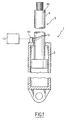
- FIG. 1 is a schematic view in longitudinal section of a telescopic device according to a first embodiment,
- FIG. 2 is a partial schematic view in elevation and with cutaway of a rod of the telescopic device according to the first embodiment,
- FIG. 3 is a view similar to that of FIG. 2 of the rod of the telescopic device according to a first variant of the first embodiment,
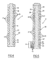
- Figures 4 and 5 are partial schematic longitudinal sectional views of the rod of the telescopic device, according to a second and a third variant of the first embodiment.
L'invention est ici décrite en application à un dispositif télescopique formant un amortisseur de suspension de véhicule automobile.The invention is here described in application to a telescopic device forming a motor vehicle suspension damper.
En référence à la figure 1 et conformément au premier mode de réalisation, l'amortisseur, généralement désigné en 1, comprend de façon connue en soi un cylindre 2 recevant à coulissement une tige 3 représentée schématiquement.Referring to Figure 1 and according to the first embodiment, the damper, generally designated 1, comprises in known manner a
En référence également à la figure 2, la tige 3 comporte des zones magnétiques et des zones amagnétiques formant des singularités magnétiques agencées le long de la tige en motifs dont au moins un a une configuration particulière pour constituer un motif de référence. Les zones magnétiques sont non magnétisées.With reference also to FIG. 2, the
La tige 3 comprend ainsi un noyau 4 en matériau amagnétique qui est pourvu extérieurement de gorges 5, 6 délimitant entre elles des collerettes 7, 8.The
Les gorges 5 ont une largeur identique. La gorge 6 a une largeur différente de celle des gorges 5. Les gorges 5, 6 reçoivent respectivement des couches magnétiques 9, 10 de largeur correspondante. Les couches magnétiques 9, 10 ont une surface externe qui affleure la surface externe des collerettes 7, 8 de telle manière que la tige 3 a une surface extérieure lisse. Ceci permet d'assurer un bon contact de la surface extérieure avec les éléments d'étanchéité non représentés qui équipent de façon classique le cylindre 2.The
Les collerettes 7 ont une largeur identique. La collerette 8 a une largeur différente de celle des collerettes 7.The
Les couches magnétiques 9, 10 et les collerettes 7, 8 constituent des singularités magnétiques. La couche 10 et la collerette 8 forment chacune un motif unique, représentatif d'un point particulier sur l'axe de la tige 3. Ces motifs sont qualifiés de motifs de référence. Les couches 9 et les collerettes 7 forment des motifs que l'on qualifie de relatifs puisqu'ils peuvent permettre de localiser un point sur l'axe de la tige 3 en partant d'un motif de référence comme cela sera expliqué par la suite.The
L'amortisseur 1 comprend également un dispositif de détection pour détecter une position de la tige 3 par rapport au cylindre 2.The
Le dispositif de détection comprend une barrette 11 de détecteurs magnétiques 12 adjacents. Les détecteurs 12 sont ici des détecteurs à effet HALL et sont associés à des aimants permanents pour détecter de façon connue en elle-même une caractéristique représentative d'un champ magnétique produit par les aimants. La barrette 11 est fixée sur le cylindre 2 et s'étend parallèlement à la tige 3 en regard de la surface extérieure de celle-ci. Par cette disposition et la juxtaposition des champs des détecteurs magnétiques 12 (également appelés champ ou cônes de sensibilité), la barrette 11 a un champ global couvrant une zone de la surface extérieure de la tige 3 qui présente une dimension axiale supérieure à une dimension axiale des motifs de référence. Les détecteurs magnétiques 12 sont reliés à une unité de traitement 13 dans laquelle sont mémorisées les positions des motifs de référence sur la tige 3.The detection device comprises a
Le fonctionnement du dispositif de détection va maintenant être décrit.The operation of the detection device will now be described.
Le flux magnétique produit par les aimants va subir une variation selon qu'ils se trouvent en regard d'une collerette ou d'une gorge. Cette variation va être détectée par les détecteurs associés. Ainsi, pour une position donnée de la tige 3 par rapport au cylindre 2 et donc à la barrette 11, les détecteurs 12 en regard d'une collerette vont émettre un signal représentatif de la présence de la collerette tandis que les détecteurs 12 en regard d'une gorge vont émettre un signal représentatif de la présence de la gorge. Si la collerette en question est une collerette 8 ou la gorge en question est une gorge 6, la zone de la tige 3 en regard de ces détecteurs 12 est identifiée de sorte que l'unité de traitement 13 peut en déduire la position de la tige 3. En revanche, si la collerette en question est une collerette 7 ou la gorge en question est une gorge 5, cette seule information ne suffit pas à identifier la zone de la tige 3.The magnetic flux produced by the magnets will undergo a variation depending on whether they are facing a flange or a groove. This variation will be detected by the associated detectors. Thus, for a given position of the
Lors du fonctionnement de l'amortisseur 1, la tige 3 est amenée à coulisser dans le cylindre 2. Après qu'un motif de référence a été identifié et le mouvement se poursuivant, l'unité de traitement effectue un comptage des motifs relatifs de sorte que l'unité de traitement peut à tout moment déterminer la distance séparant la zone de la tige 3 en regard des détecteurs magnétiques 12 et le motif de référence identifié. A partir de cette information, l'unité de traitement peut déterminer la position de la tige 3 par rapport au cylindre 2.During the operation of the
Ainsi, le déplacement de la tige comportant les zones magnétiques et amagnétiques devant les aimants fixes produit une variation du flux de ceux-ci qui est détecté par les détecteurs associés. On notera que l'utilisation de détecteurs alimentés en courant continu permet de simplifier l'alimentation des détecteurs en particulier lorsque le dispositif est implanté sur un véhicule automobile où l'énergie électrique est fournie par une batterie.Thus, the displacement of the rod comprising the magnetic and non-magnetic zones in front of the fixed magnets produces a variation in the flux of these which is detected by the associated detectors. Note that the use of DC-powered detectors simplifies the power supply detectors especially when the device is located on a motor vehicle where the electrical energy is supplied by a battery.
Selon une première variante et en référence à la figure 3, la tige 3 comprend un noyau 14 en matériau magnétique qui est pourvu extérieurement de gorges 15, 16 délimitant entre elles des collerettes 17, 18.According to a first variant and with reference to Figure 3, the
Les gorges 15 ont une largeur identique. La gorge 16 a une largeur différente de celle des gorges 15. Les gorges 15, 16 reçoivent respectivement des couches amagnétiques 19, 20 de largeur correspondante. Les couches amagnétiques 19, 20 ont une surface externe qui affleure la surface externe des collerettes 17, 18 de telle manière que la tige 3 a une surface extérieure lisse.The
Le fonctionnement du dispositif selon cette variante est identique à celui précédemment décrit.The operation of the device according to this variant is identical to that previously described.
Selon une deuxième variante et en référence à la figure 4, le noyau 14 est recouvert d'une couche de remplissage 21 qui est en matériau amagnétique. La couche de remplissage remplit les gorges 15, 16 et recouvre les collerettes 17, 18 en présentant une surface extérieure 22 lisse. La couche de remplissage 21 peut par exemple être déposée par projection thermique ou par électrolyse.According to a second variant and with reference to FIG. 4, the
Selon une troisième variante et en référence à la figure 5, la tige 3 comprend un noyau 24 en matériau magnétique qui est pourvu extérieurement de gorges 25, 26 délimitant entre elles des collerettes 27, 28. Les gorges 25, 26 et les collerettes 27, 28 ont comme précédemment des largeurs différentes pour former des motifs de référence et des motifs relatifs.According to a third variant and with reference to FIG. 5, the
Le noyau 24 est reçu dans un tube 29 en matériau amagnétique ayant une surface extérieure 30 lisse. Le tube 29 peut simplement procurer à la tige 3 une surface extérieure lisse simplifiant l'étanchéité avec le cylindre 2 ou assurer également un rôle de renforcement mécanique.The
Bien entendu, l'invention n'est pas limitée au mode de réalisation décrit et on peut y apporter des variantes de réalisation sans sortir du cadre de l'invention tel que défini par les revendications.Of course, the invention is not limited to the embodiment described and variants may be provided without departing from the scope of the invention as defined by the claims.
En particulier, bien que l'invention ait été décrite en relation avec un amortisseur de suspension de véhicule automobile, l'invention n'est pas limitée à cette application et peut être utilisée également dans tout dispositif télescopique comme des vérins, des éléments d'accouplement élastique...In particular, although the invention has been described in relation to a motor vehicle suspension damper, the invention is not limited to this invention. application and can be used also in any telescopic device such as cylinders, elastic coupling elements ...
Les détecteurs 12 peuvent être également des détecteurs magnétorésistifs.The
Bien que l'ensemble formés par les détecteurs 12 ait été décrit sous la forme d'une barrette, les détecteurs 12 peuvent être indépendants les uns des autres et par exemple simplement alignés sur une direction commune.Although the assembly formed by the
La tige 3 peut également comporter en variante un noyau amagnétique ou magnétique ayant une surface externe recouverte de parties magnétiques et amagnétiques formant les motifs. Les parties magnétiques et amagnétiques sont par exemple des anneaux de faible épaisseur qui ont des largeurs différentes pour former des motifs de référence ou des motifs relatifs.The
Dans tous les modes de réalisation décrits précédemment, le noyau peut être reçu dans un tube qui assure une fonction de protection des singularités magnétiques et/ou une fonction de renforcement mécanique de la tige, ou qui procure une surface externe lisse à la tige.In all the embodiments described above, the core may be received in a tube which provides a protection function of the magnetic singularities and / or a function of mechanical reinforcement of the rod, or which provides a smooth external surface to the rod.
Dans le premier mode de réalisation, les motifs de référence peuvent être obtenus par la variation de la largeur des gorges et/ou de l'espacement des gorges.In the first embodiment, the reference patterns can be obtained by varying the width of the grooves and / or the spacing of the grooves.
Dans le premier mode de réalisation, pour obtenir une surface externe lisse de la tige, il est possible de recouvrir la tige d'une couche de protection par exemple à base de chrome dur.In the first embodiment, to obtain a smooth outer surface of the rod, it is possible to cover the rod with a protective layer for example based on hard chrome.
Les singularités magnétiques peuvent être réalisées en combinant les modes de réalisation décrits.The magnetic singularities can be achieved by combining the embodiments described.
Claims (7)
- Telescopic device (1) comprising a cylinder (2) in which a rod (3) is slidingly housed, and a device for detecting a position of the rod relative to the cylinder, the rod having a succession of magnetic and non-magnetic zones forming magnetic singularities placed along the rod in patterns (5, 6, 7, 8; 15, 16, 17, 18; 25, 26, 27, 28: 51, 52; 61), the detection device being fixed relative to the cylinder and comprising an assembly (11) of at least two magnetic detectors (12) that are associated with permanent magnets, which telescopic device is characterized in that at least one pattern (6, 8; 16, 18; 26, 28) has a particular configuration for constituting a reference pattern and in that said at least two detectors (12) are placed adjacently along an axial direction of the rod in such a way that the detector assembly has a field covering a zone of the rod having an axial dimension greater than an axial dimension of the reference pattern in order to measure modulations in magnetic fields produced by these magnets during a displacement of the rod.
- Telescopic device (1) according to Claim 1, characterized in that the rod (3) comprises a non-magnetic core (4) provided on the outside with grooves (5, 6) that receive a layer of magnetic material (9, 10).
- Telescopic device (1) according to Claim 1, characterized in that the rod (3) comprises a magnetic core (14; 24) provided on the outside with grooves (15, 16; 25, 26) designed to form the patterns.
- Telescopic device (1) according to Claim 3, characterized in that the grooves (15, 16) receive a layer of non-magnetic material (19, 20).
- Telescopic device (1) according to Claim 4, characterized in that the layer of non-magnetic material (21) covers the core (24) and has a smooth external surface (22).
- Telescopic device (1) according to Claim 3, characterized in that this core (14) is received in a tube (29) made of non-magnetic material having a smooth external surface (30).
- Telescopic device (1) according to Claim 1, characterized in that the detectors (12) are Hall-effect detectors.
Priority Applications (1)
| Application Number | Priority Date | Filing Date | Title |
|---|---|---|---|
| PL05732822T PL1721087T3 (en) | 2004-03-03 | 2005-03-03 | Telescopic device provided with a position detecting electromagnetic unit |
Applications Claiming Priority (2)
| Application Number | Priority Date | Filing Date | Title |
|---|---|---|---|
| FR0402175A FR2867237B1 (en) | 2004-03-03 | 2004-03-03 | TELESCOPIC DEVICE WITH ELECTROMAGNETIC POSITION DETECTION |
| PCT/FR2005/000500 WO2005088154A1 (en) | 2004-03-03 | 2005-03-03 | Telescopic device provided with a position detecting electromagnetic unit |
Publications (2)
| Publication Number | Publication Date |
|---|---|
| EP1721087A1 EP1721087A1 (en) | 2006-11-15 |
| EP1721087B1 true EP1721087B1 (en) | 2008-01-16 |
Family
ID=34855001
Family Applications (1)
| Application Number | Title | Priority Date | Filing Date |
|---|---|---|---|
| EP05732822A Not-in-force EP1721087B1 (en) | 2004-03-03 | 2005-03-03 | Telescopic device provided with a position detecting electromagnetic unit |
Country Status (7)
| Country | Link |
|---|---|
| EP (1) | EP1721087B1 (en) |
| AT (1) | ATE384211T1 (en) |
| DE (1) | DE602005004385T2 (en) |
| ES (1) | ES2300008T3 (en) |
| FR (1) | FR2867237B1 (en) |
| PL (1) | PL1721087T3 (en) |
| WO (1) | WO2005088154A1 (en) |
Cited By (1)
| Publication number | Priority date | Publication date | Assignee | Title |
|---|---|---|---|---|
| EP2226514A1 (en) | 2009-03-06 | 2010-09-08 | SICK STEGMANN GmbH | Device for measuring the axial position of a piston rod relatively to a cylinder housing |
Families Citing this family (4)
| Publication number | Priority date | Publication date | Assignee | Title |
|---|---|---|---|---|
| GB2429757B (en) * | 2004-07-14 | 2009-07-29 | Tenneco Automotive Operating | Shock absorber with integrated displacement sensor |
| CN100462572C (en) * | 2007-07-10 | 2009-02-18 | 中国航空工业第一集团公司北京航空精密机械研究所 | Smart-moving action shaft |
| GB0903961D0 (en) * | 2009-01-27 | 2009-04-22 | Renishaw Plc | Magnetic encoder scale |
| CN112594319A (en) * | 2020-12-11 | 2021-04-02 | 中铁桥研科技有限公司 | Viscous damper with magnetic grid positioning device and displacement calculation method thereof |
Family Cites Families (5)
| Publication number | Priority date | Publication date | Assignee | Title |
|---|---|---|---|---|
| US4717874A (en) * | 1984-02-10 | 1988-01-05 | Kabushiki Kaisha Sg | Reluctance type linear position detection device |
| SE501291C2 (en) * | 1992-09-23 | 1995-01-09 | Mecman Ab Rexroth | Device for positioning piston cylinder assemblies |
| JPH07229760A (en) * | 1994-02-16 | 1995-08-29 | Yamaha Motor Co Ltd | Encoder |
| DE10010042A1 (en) * | 2000-01-13 | 2001-07-19 | Continental Teves Ag & Co Ohg | Linear displacement sensor and its use as an actuating device for motor vehicles |
| EP1520119A1 (en) * | 2002-07-02 | 2005-04-06 | Continental Teves AG & Co. oHG | Shock absorber and assembly for recording shock absorber displacement |
-
2004
- 2004-03-03 FR FR0402175A patent/FR2867237B1/en not_active Expired - Fee Related
-
2005
- 2005-03-03 DE DE602005004385T patent/DE602005004385T2/en active Active
- 2005-03-03 WO PCT/FR2005/000500 patent/WO2005088154A1/en active IP Right Grant
- 2005-03-03 ES ES05732822T patent/ES2300008T3/en active Active
- 2005-03-03 EP EP05732822A patent/EP1721087B1/en not_active Not-in-force
- 2005-03-03 PL PL05732822T patent/PL1721087T3/en unknown
- 2005-03-03 AT AT05732822T patent/ATE384211T1/en not_active IP Right Cessation
Cited By (2)
| Publication number | Priority date | Publication date | Assignee | Title |
|---|---|---|---|---|
| EP2226514A1 (en) | 2009-03-06 | 2010-09-08 | SICK STEGMANN GmbH | Device for measuring the axial position of a piston rod relatively to a cylinder housing |
| US8151636B2 (en) | 2009-03-06 | 2012-04-10 | Sick Stegmann Gmbh | Device for measuring the axial position of a piston rod relative to a cylinder housing |
Also Published As
| Publication number | Publication date |
|---|---|
| WO2005088154A1 (en) | 2005-09-22 |
| PL1721087T3 (en) | 2008-04-30 |
| DE602005004385T2 (en) | 2009-01-15 |
| ATE384211T1 (en) | 2008-02-15 |
| EP1721087A1 (en) | 2006-11-15 |
| ES2300008T3 (en) | 2008-06-01 |
| DE602005004385D1 (en) | 2008-03-06 |
| FR2867237B1 (en) | 2008-04-18 |
| FR2867237A1 (en) | 2005-09-09 |
Similar Documents
| Publication | Publication Date | Title |
|---|---|---|
| EP1721087B1 (en) | Telescopic device provided with a position detecting electromagnetic unit | |
| EP0729582B1 (en) | Speed and/or position incremental sensor | |
| EP1781959B1 (en) | Wheel brake comprising a wear sensor | |
| FR2606873A1 (en) | PISTON POSITION DETECTOR FOR A PRESSURIZED FLUID CYLINDER | |
| FR3071605B1 (en) | MODULE FOR DETECTING A ROTARY HANDLE OF A MOTORIZED VEHICLE | |
| FR2764372A1 (en) | MAGNETIC POSITION SENSOR | |
| WO2007077406A2 (en) | Short stroke magnetic position sensor, in particular for measuring a steering column twist | |
| EP0682238B1 (en) | Magnetic torquemeter for measuring absolute values of torsion and torque | |
| WO2004031693A1 (en) | Variable reluctance position sensor | |
| EP1857783B1 (en) | Position sensor encoder, with stabilising effect for resetting the magnetic induction to zero | |
| FR2757943A1 (en) | ENCODER FOR POSITION SENSOR AND SENSOR BY APPLYING | |
| FR2743890A1 (en) | EDGE CURRENT SENSOR AND TUBE CONTROL TOOLS COMPRISING AT LEAST ONE SUCH SENSOR | |
| EP0798541B1 (en) | Magnetic position sensor | |
| FR2801969A1 (en) | NON-CONTACT ANGLE SHIFT ANALOG SENSOR | |
| EP1502081A1 (en) | Angular position magnetic sensor device | |
| EP0593351B1 (en) | Sensor for measuring the angular displacement of a moving part | |
| FR2716713A1 (en) | Installation for measuring a stroke or an angle. | |
| EP1600738B1 (en) | Magnetic detection device with a dual magnetic flux path | |
| EP3244167B1 (en) | Magnetic component for hall-effect sensor, electrical assembly and electric supercharger comprising such a magnetic component | |
| EP1224110B1 (en) | Electronic steering column module | |
| FR2837569A1 (en) | Speed sensor for mobile targets, has probe placed along OZ axis of sensor such that when tooth of mobile target is absent, magnetic induction of magnet passes through a probe along direction opposite to magnetization direction | |
| FR2767584A1 (en) | ROTATION SPEED INDICATOR OPERATING BY INDUCTION TO MEET THE ROTATION SPEED OF A MOTOR VEHICLE WHEEL | |
| FR3080679A1 (en) | DEVICE FOR DETECTING THE ANGULAR POSITION OF A ROTOR OF A ROTATING ELECTRIC MACHINE | |
| FR2829574A1 (en) | Position sensors for magnetic object moving along axis in ferromagnetic cylinder, has magnetic sub-circuits in airgaps at ends or along cylindrical casing formed from two half shells | |
| WO2005003686A2 (en) | Position sensor by detection of a tangential magnetic field |
Legal Events
| Date | Code | Title | Description |
|---|---|---|---|
| PUAI | Public reference made under article 153(3) epc to a published international application that has entered the european phase |
Free format text: ORIGINAL CODE: 0009012 |
|
| 17P | Request for examination filed |
Effective date: 20060904 |
|
| AK | Designated contracting states |
Kind code of ref document: A1 Designated state(s): AT BE BG CH CY CZ DE DK EE ES FI FR GB GR HU IE IS IT LI LT LU MC NL PL PT RO SE SI SK TR |
|
| RIN1 | Information on inventor provided before grant (corrected) |
Inventor name: QUEDEVILLE, NICOLAS Inventor name: RAMPILLON, FLORENT Inventor name: MAERKY, CHRISTOPHE |
|
| DAX | Request for extension of the european patent (deleted) | ||
| GRAP | Despatch of communication of intention to grant a patent |
Free format text: ORIGINAL CODE: EPIDOSNIGR1 |
|
| GRAS | Grant fee paid |
Free format text: ORIGINAL CODE: EPIDOSNIGR3 |
|
| GRAA | (expected) grant |
Free format text: ORIGINAL CODE: 0009210 |
|
| AK | Designated contracting states |
Kind code of ref document: B1 Designated state(s): AT BE BG CH CY CZ DE DK EE ES FI FR GB GR HU IE IS IT LI LT LU MC NL PL PT RO SE SI SK TR |
|
| REG | Reference to a national code |
Ref country code: GB Ref legal event code: FG4D Free format text: NOT ENGLISH |
|
| REG | Reference to a national code |
Ref country code: CH Ref legal event code: EP |
|
| REG | Reference to a national code |
Ref country code: IE Ref legal event code: FG4D Free format text: LANGUAGE OF EP DOCUMENT: FRENCH |
|
| GBT | Gb: translation of ep patent filed (gb section 77(6)(a)/1977) |
Effective date: 20080213 |
|
| REF | Corresponds to: |
Ref document number: 602005004385 Country of ref document: DE Date of ref document: 20080306 Kind code of ref document: P |
|
| REG | Reference to a national code |
Ref country code: SE Ref legal event code: TRGR |
|
| REG | Reference to a national code |
Ref country code: PL Ref legal event code: T3 |
|
| PG25 | Lapsed in a contracting state [announced via postgrant information from national office to epo] |
Ref country code: NL Free format text: LAPSE BECAUSE OF FAILURE TO SUBMIT A TRANSLATION OF THE DESCRIPTION OR TO PAY THE FEE WITHIN THE PRESCRIBED TIME-LIMIT Effective date: 20080116 |
|
| REG | Reference to a national code |
Ref country code: ES Ref legal event code: FG2A Ref document number: 2300008 Country of ref document: ES Kind code of ref document: T3 |
|
| NLV1 | Nl: lapsed or annulled due to failure to fulfill the requirements of art. 29p and 29m of the patents act | ||
| PG25 | Lapsed in a contracting state [announced via postgrant information from national office to epo] |
Ref country code: LT Free format text: LAPSE BECAUSE OF FAILURE TO SUBMIT A TRANSLATION OF THE DESCRIPTION OR TO PAY THE FEE WITHIN THE PRESCRIBED TIME-LIMIT Effective date: 20080116 Ref country code: FI Free format text: LAPSE BECAUSE OF FAILURE TO SUBMIT A TRANSLATION OF THE DESCRIPTION OR TO PAY THE FEE WITHIN THE PRESCRIBED TIME-LIMIT Effective date: 20080116 Ref country code: IS Free format text: LAPSE BECAUSE OF FAILURE TO SUBMIT A TRANSLATION OF THE DESCRIPTION OR TO PAY THE FEE WITHIN THE PRESCRIBED TIME-LIMIT Effective date: 20080516 |
|
| PG25 | Lapsed in a contracting state [announced via postgrant information from national office to epo] |
Ref country code: AT Free format text: LAPSE BECAUSE OF FAILURE TO SUBMIT A TRANSLATION OF THE DESCRIPTION OR TO PAY THE FEE WITHIN THE PRESCRIBED TIME-LIMIT Effective date: 20080116 Ref country code: BG Free format text: LAPSE BECAUSE OF FAILURE TO SUBMIT A TRANSLATION OF THE DESCRIPTION OR TO PAY THE FEE WITHIN THE PRESCRIBED TIME-LIMIT Effective date: 20080416 |
|
| PG25 | Lapsed in a contracting state [announced via postgrant information from national office to epo] |
Ref country code: SI Free format text: LAPSE BECAUSE OF FAILURE TO SUBMIT A TRANSLATION OF THE DESCRIPTION OR TO PAY THE FEE WITHIN THE PRESCRIBED TIME-LIMIT Effective date: 20080116 Ref country code: PT Free format text: LAPSE BECAUSE OF FAILURE TO SUBMIT A TRANSLATION OF THE DESCRIPTION OR TO PAY THE FEE WITHIN THE PRESCRIBED TIME-LIMIT Effective date: 20080616 |
|
| REG | Reference to a national code |
Ref country code: IE Ref legal event code: FD4D |
|
| PG25 | Lapsed in a contracting state [announced via postgrant information from national office to epo] |
Ref country code: SK Free format text: LAPSE BECAUSE OF FAILURE TO SUBMIT A TRANSLATION OF THE DESCRIPTION OR TO PAY THE FEE WITHIN THE PRESCRIBED TIME-LIMIT Effective date: 20080116 Ref country code: MC Free format text: LAPSE BECAUSE OF NON-PAYMENT OF DUE FEES Effective date: 20080331 Ref country code: IE Free format text: LAPSE BECAUSE OF FAILURE TO SUBMIT A TRANSLATION OF THE DESCRIPTION OR TO PAY THE FEE WITHIN THE PRESCRIBED TIME-LIMIT Effective date: 20080116 Ref country code: DK Free format text: LAPSE BECAUSE OF FAILURE TO SUBMIT A TRANSLATION OF THE DESCRIPTION OR TO PAY THE FEE WITHIN THE PRESCRIBED TIME-LIMIT Effective date: 20080116 |
|
| PLBE | No opposition filed within time limit |
Free format text: ORIGINAL CODE: 0009261 |
|
| STAA | Information on the status of an ep patent application or granted ep patent |
Free format text: STATUS: NO OPPOSITION FILED WITHIN TIME LIMIT |
|
| PG25 | Lapsed in a contracting state [announced via postgrant information from national office to epo] |
Ref country code: RO Free format text: LAPSE BECAUSE OF FAILURE TO SUBMIT A TRANSLATION OF THE DESCRIPTION OR TO PAY THE FEE WITHIN THE PRESCRIBED TIME-LIMIT Effective date: 20080116 |
|
| 26N | No opposition filed |
Effective date: 20081017 |
|
| PG25 | Lapsed in a contracting state [announced via postgrant information from national office to epo] |
Ref country code: EE Free format text: LAPSE BECAUSE OF FAILURE TO SUBMIT A TRANSLATION OF THE DESCRIPTION OR TO PAY THE FEE WITHIN THE PRESCRIBED TIME-LIMIT Effective date: 20080116 |
|
| PG25 | Lapsed in a contracting state [announced via postgrant information from national office to epo] |
Ref country code: CY Free format text: LAPSE BECAUSE OF FAILURE TO SUBMIT A TRANSLATION OF THE DESCRIPTION OR TO PAY THE FEE WITHIN THE PRESCRIBED TIME-LIMIT Effective date: 20080116 |
|
| REG | Reference to a national code |
Ref country code: CH Ref legal event code: PL |
|
| PG25 | Lapsed in a contracting state [announced via postgrant information from national office to epo] |
Ref country code: CH Free format text: LAPSE BECAUSE OF NON-PAYMENT OF DUE FEES Effective date: 20090331 Ref country code: LI Free format text: LAPSE BECAUSE OF NON-PAYMENT OF DUE FEES Effective date: 20090331 |
|
| PG25 | Lapsed in a contracting state [announced via postgrant information from national office to epo] |
Ref country code: HU Free format text: LAPSE BECAUSE OF FAILURE TO SUBMIT A TRANSLATION OF THE DESCRIPTION OR TO PAY THE FEE WITHIN THE PRESCRIBED TIME-LIMIT Effective date: 20080717 Ref country code: LU Free format text: LAPSE BECAUSE OF NON-PAYMENT OF DUE FEES Effective date: 20080303 |
|
| PG25 | Lapsed in a contracting state [announced via postgrant information from national office to epo] |
Ref country code: TR Free format text: LAPSE BECAUSE OF FAILURE TO SUBMIT A TRANSLATION OF THE DESCRIPTION OR TO PAY THE FEE WITHIN THE PRESCRIBED TIME-LIMIT Effective date: 20080116 |
|
| PG25 | Lapsed in a contracting state [announced via postgrant information from national office to epo] |
Ref country code: GR Free format text: LAPSE BECAUSE OF FAILURE TO SUBMIT A TRANSLATION OF THE DESCRIPTION OR TO PAY THE FEE WITHIN THE PRESCRIBED TIME-LIMIT Effective date: 20080417 |
|
| REG | Reference to a national code |
Ref country code: FR Ref legal event code: PLFP Year of fee payment: 12 |
|
| PGFP | Annual fee paid to national office [announced via postgrant information from national office to epo] |
Ref country code: ES Payment date: 20160329 Year of fee payment: 12 Ref country code: DE Payment date: 20160316 Year of fee payment: 12 Ref country code: CZ Payment date: 20160224 Year of fee payment: 12 |
|
| PGFP | Annual fee paid to national office [announced via postgrant information from national office to epo] |
Ref country code: SE Payment date: 20160318 Year of fee payment: 12 Ref country code: GB Payment date: 20160318 Year of fee payment: 12 Ref country code: PL Payment date: 20160218 Year of fee payment: 12 |
|
| PGFP | Annual fee paid to national office [announced via postgrant information from national office to epo] |
Ref country code: BE Payment date: 20160330 Year of fee payment: 12 Ref country code: IT Payment date: 20160317 Year of fee payment: 12 Ref country code: FR Payment date: 20160331 Year of fee payment: 12 |
|
| REG | Reference to a national code |
Ref country code: DE Ref legal event code: R119 Ref document number: 602005004385 Country of ref document: DE |
|
| PG25 | Lapsed in a contracting state [announced via postgrant information from national office to epo] |
Ref country code: CZ Free format text: LAPSE BECAUSE OF NON-PAYMENT OF DUE FEES Effective date: 20170303 |
|
| REG | Reference to a national code |
Ref country code: SE Ref legal event code: EUG |
|
| GBPC | Gb: european patent ceased through non-payment of renewal fee |
Effective date: 20170303 |
|
| PG25 | Lapsed in a contracting state [announced via postgrant information from national office to epo] |
Ref country code: SE Free format text: LAPSE BECAUSE OF NON-PAYMENT OF DUE FEES Effective date: 20170304 |
|
| REG | Reference to a national code |
Ref country code: FR Ref legal event code: ST Effective date: 20171130 |
|
| PG25 | Lapsed in a contracting state [announced via postgrant information from national office to epo] |
Ref country code: DE Free format text: LAPSE BECAUSE OF NON-PAYMENT OF DUE FEES Effective date: 20171003 Ref country code: FR Free format text: LAPSE BECAUSE OF NON-PAYMENT OF DUE FEES Effective date: 20170331 |
|
| PG25 | Lapsed in a contracting state [announced via postgrant information from national office to epo] |
Ref country code: GB Free format text: LAPSE BECAUSE OF NON-PAYMENT OF DUE FEES Effective date: 20170303 Ref country code: IT Free format text: LAPSE BECAUSE OF NON-PAYMENT OF DUE FEES Effective date: 20170303 |
|
| REG | Reference to a national code |
Ref country code: BE Ref legal event code: MM Effective date: 20170331 |
|
| PG25 | Lapsed in a contracting state [announced via postgrant information from national office to epo] |
Ref country code: BE Free format text: LAPSE BECAUSE OF NON-PAYMENT OF DUE FEES Effective date: 20170331 |
|
| REG | Reference to a national code |
Ref country code: ES Ref legal event code: FD2A Effective date: 20180629 |
|
| PG25 | Lapsed in a contracting state [announced via postgrant information from national office to epo] |
Ref country code: ES Free format text: LAPSE BECAUSE OF NON-PAYMENT OF DUE FEES Effective date: 20170304 |
|
| PG25 | Lapsed in a contracting state [announced via postgrant information from national office to epo] |
Ref country code: PL Free format text: LAPSE BECAUSE OF NON-PAYMENT OF DUE FEES Effective date: 20170303 |