EP1720426B1 - Electric toothbrush having a flexible drive shaft - Google Patents
Electric toothbrush having a flexible drive shaft Download PDFInfo
- Publication number
- EP1720426B1 EP1720426B1 EP05723235.7A EP05723235A EP1720426B1 EP 1720426 B1 EP1720426 B1 EP 1720426B1 EP 05723235 A EP05723235 A EP 05723235A EP 1720426 B1 EP1720426 B1 EP 1720426B1
- Authority
- EP
- European Patent Office
- Prior art keywords
- drive shaft
- spring
- motor
- bristle holder
- spring element
- Prior art date
- Legal status (The legal status is an assumption and is not a legal conclusion. Google has not performed a legal analysis and makes no representation as to the accuracy of the status listed.)
- Not-in-force
Links
- 239000000463 material Substances 0.000 claims description 43
- 230000033001 locomotion Effects 0.000 claims description 26
- 238000006073 displacement reaction Methods 0.000 claims description 20
- 230000009467 reduction Effects 0.000 claims description 4
- 238000012546 transfer Methods 0.000 claims description 4
- 230000001680 brushing effect Effects 0.000 description 28
- 230000007246 mechanism Effects 0.000 description 21
- 230000036961 partial effect Effects 0.000 description 12
- 238000004140 cleaning Methods 0.000 description 5
- 238000000034 method Methods 0.000 description 5
- 239000004677 Nylon Substances 0.000 description 3
- 230000001419 dependent effect Effects 0.000 description 3
- 229920001778 nylon Polymers 0.000 description 3
- 230000001154 acute effect Effects 0.000 description 2
- 230000004075 alteration Effects 0.000 description 2
- 238000013459 approach Methods 0.000 description 2
- 230000007423 decrease Effects 0.000 description 2
- 238000013461 design Methods 0.000 description 2
- 238000012986 modification Methods 0.000 description 2
- 230000004048 modification Effects 0.000 description 2
- 230000000737 periodic effect Effects 0.000 description 2
- 229920006324 polyoxymethylene Polymers 0.000 description 2
- 230000000717 retained effect Effects 0.000 description 2
- 238000012360 testing method Methods 0.000 description 2
- 229920004943 Delrin® Polymers 0.000 description 1
- 230000005483 Hooke's law Effects 0.000 description 1
- 229920012196 Polyoxymethylene Copolymer Polymers 0.000 description 1
- 229910000831 Steel Inorganic materials 0.000 description 1
- 239000011354 acetal resin Substances 0.000 description 1
- 229920000122 acrylonitrile butadiene styrene Polymers 0.000 description 1
- 230000004913 activation Effects 0.000 description 1
- 229910052782 aluminium Inorganic materials 0.000 description 1
- XAGFODPZIPBFFR-UHFFFAOYSA-N aluminium Chemical compound [Al] XAGFODPZIPBFFR-UHFFFAOYSA-N 0.000 description 1
- 238000005452 bending Methods 0.000 description 1
- 230000009286 beneficial effect Effects 0.000 description 1
- 230000005540 biological transmission Effects 0.000 description 1
- 239000011248 coating agent Substances 0.000 description 1
- 238000000576 coating method Methods 0.000 description 1
- 230000003247 decreasing effect Effects 0.000 description 1
- 230000003292 diminished effect Effects 0.000 description 1
- 230000001747 exhibiting effect Effects 0.000 description 1
- 230000000670 limiting effect Effects 0.000 description 1
- 229910052751 metal Inorganic materials 0.000 description 1
- 239000002184 metal Substances 0.000 description 1
- 150000002739 metals Chemical class 0.000 description 1
- 230000000704 physical effect Effects 0.000 description 1
- 229920013636 polyphenyl ether polymer Polymers 0.000 description 1
- 229920001955 polyphenylene ether Polymers 0.000 description 1
- 230000002829 reductive effect Effects 0.000 description 1
- 230000001105 regulatory effect Effects 0.000 description 1
- 239000010959 steel Substances 0.000 description 1
Images


Classifications
-
- A—HUMAN NECESSITIES
- A46—BRUSHWARE
- A46B—BRUSHES
- A46B13/00—Brushes with driven brush bodies or carriers
- A46B13/02—Brushes with driven brush bodies or carriers power-driven carriers
-
- A—HUMAN NECESSITIES
- A46—BRUSHWARE
- A46B—BRUSHES
- A46B13/00—Brushes with driven brush bodies or carriers
-
- A—HUMAN NECESSITIES
- A61—MEDICAL OR VETERINARY SCIENCE; HYGIENE
- A61C—DENTISTRY; APPARATUS OR METHODS FOR ORAL OR DENTAL HYGIENE
- A61C17/00—Devices for cleaning, polishing, rinsing or drying teeth, teeth cavities or prostheses; Saliva removers; Dental appliances for receiving spittle
- A61C17/16—Power-driven cleaning or polishing devices
- A61C17/22—Power-driven cleaning or polishing devices with brushes, cushions, cups, or the like
- A61C17/222—Brush body details, e.g. the shape thereof or connection to handle
-
- A—HUMAN NECESSITIES
- A61—MEDICAL OR VETERINARY SCIENCE; HYGIENE
- A61C—DENTISTRY; APPARATUS OR METHODS FOR ORAL OR DENTAL HYGIENE
- A61C17/00—Devices for cleaning, polishing, rinsing or drying teeth, teeth cavities or prostheses; Saliva removers; Dental appliances for receiving spittle
- A61C17/16—Power-driven cleaning or polishing devices
- A61C17/22—Power-driven cleaning or polishing devices with brushes, cushions, cups, or the like
- A61C17/32—Power-driven cleaning or polishing devices with brushes, cushions, cups, or the like reciprocating or oscillating
- A61C17/34—Power-driven cleaning or polishing devices with brushes, cushions, cups, or the like reciprocating or oscillating driven by electric motor
- A61C17/3409—Power-driven cleaning or polishing devices with brushes, cushions, cups, or the like reciprocating or oscillating driven by electric motor characterized by the movement of the brush body
- A61C17/3436—Rotation around the axis perpendicular to the plane defined by the bristle holder
Definitions
- the present invention relates to the field of toothbrushes, and more particularly, the invention relates to the field of electrically powered toothbrushes.
- Toothbrushes have traditionally utilized one or more groups of bristles that are fixed or otherwise attached to the head or end of the toothbrush. Toothbrushes are also known that utilize movable bristle sets or holders that are mechanically or electrically powered. Typically, an electric motor and a drive mechanism are retained within the body of the toothbrush and are coupled to the movable bristle sets or holders. Upon actuation of the motor and drive mechanism, the bristle holders may undergo a variety of different types of motion. Typically, one or more batteries are also provided within the body of the toothbrush to power the drive mechanism and impart motion to the movable bristle holders.
- power consumption of the electric motor is generally a function of the rate of rotation and load placed upon the motor by the drive mechanism. These parameters are dependent upon the load placed upon the brushing elements, e.g. the moving bristle holders, disposed on the brush head. It is also known that power consumption of the electric motor is also dependent upon the mechanical strain placed upon the motor, and typically, upon the output shaft of the motor.
- a significant disadvantage in using an electric toothbrush is that after some time period of repeated use, the batteries are exhausted and must be replaced. In addition to the increasingly high cost of batteries, battery replacement is often regarded by consumers as burdensome or annoying. In addition, in certain low cost disposable electric toothbrushes, the batteries may be sealed within the body of the toothbrush and not be suitable for replacement. Accordingly, a need exists for extending battery life and the time period between battery replacement in an electric toothbrush.
- the present invention may take form in various components and arrangements of components, and in various techniques, methods, or procedures and arrangements of steps.
- the referenced drawings are only for purposes of illustrating embodiments of the toothbrush according to the present invention, they are not necessarily to scale, and are not to be construed as limiting the present invention.
- the present invention provides a drive mechanism component, or components, that can limit the load that is applied to the electric motor and prevents stalling by absorbing this excess load, and thereby extends battery life.
- these components are springs or spring elements that are provided along a portion of a drive shaft in the drive mechanism.
- the spring constant can be considered. Choosing a spring constant that results in a toothbrush drive shaft that is too flexible can result in insufficient cleaning force applied to the teeth. However, choosing a spring constant that results in a drive shaft that is too rigid, can result in the spring element not absorbing the excessive load, thereby transmitting this load to the motor and failing to prevent the motor from stalling.
- an "excessive load,” as that term is used herein, is one that when applied to the drive shaft of the toothbrush, results in substantial stalling of the motor. This stalling of the motor results in a reduction in the rate of movement of the movable bristle holder by about 50% to less than about 100%, and typically by about 75% to about 95% and can result in shortened battery life.
- a toothbrush exhibits a brushing rate, without application of any load to the brush head, of about 250 to about 5000 stroke cycles per minute, in another embodiment the toothbrush exhibits a brushing rate of from about 750 to about 2000 strokes per minute, and in yet another embodiment the toothbrush exhibits a brushing rate of about 1250 strokes per minute.
- a "stroke" as used herein, is one complete cycle of movement. For a reciprocating drive shaft, a stroke includes travel in a first direction and then travel in a second, opposite direction. Upon brushing or application of a normal or typical brushing load to the bristle holders, the brushing rate can decrease to about 625 strokes per minute for a toothbrush exhibiting a brushing rate of about 1250 strokes per minute.
- the brushing rate further decreases.
- the brushing load would be deemed as "excessive" when the rate slowed to about 315 strokes per minute (corresponding to a 75% reduction in brushing rate).
- the spring portion is formed or otherwise provided along a portion of the length of the drive shaft such that during operation of the toothbrush and upon application of an excessive load to the brushing end of the drive shaft, the spring is displaced thereby absorbing a portion of the load. This in turn reduces the expression or transmission of the otherwise excessive load at the other end of the drive shaft, i.e. the motor end of the drive shaft.
- the term "brushing end” of the drive shaft refers to the end of the drive shaft that is proximate the movable bristle holder driven by the drive shaft and is operatively connected to the holder.
- the term “motor end” of the drive shaft refers to the end of the drive shaft that is proximate the electric motor that ultimately drives the drive shaft. As previously described, it is the application of an excessive load upon the motor that results in excessive power consumption. And so, by reducing or avoiding the application of excessive loads upon the motor, i.e. by provision of the spring portion, excessive power consumption is avoided.
- the spring portion is formed or otherwise provided along a portion of the drive shaft such that during normal use of the toothbrush, and without an excessive load being placed thereon, the spring is not displaced, nor displaced to any significant extent. This characteristic of the spring, during normal operation of the toothbrush, is also described as the spring remaining essentially rigid and unchanged in shape.
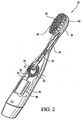
- Fig. 1 is a perspective view of an embodiment of the toothbrush 10 in accordance with the present invention.
- the toothbrush 10 comprises a body 80, a head 20, and a neck 40 extending between the handle or body 80 and the head 20.
- An actuator 70 or switch is provided along the body 80 .
- Disposed on the head 20 are a plurality of fixed bristles 60 and a collection of movable bristles 50, both of which are described and illustrated in detail by the various patents.
- Fig. 2 is a partial fragmentary view of an embodiment of the toothbrush 10 shown in Fig. 1 .
- Fig. 2 illustrates a motor 90 and a drive train or mechanism retained within the body 80 that are used to move the collection of movable bristles 50 disposed on the brush head 20.
- the movable bristles are attached to and supported by a movable bristle holder (not shown in Fig. 2 ).
- actuator 70 shown in Fig. 1
- electrical energy is directed to a motor 90.
- the motor 90 includes an output shaft 91 to which is affixed a drive gear 92.
- the drive gear 92 is engaged with a rotatable drive gear 93.
- the drive gear 93 is mounted such that it rotates about an axis A extending in a direction perpendicular to the output shaft 91 of the motor.
- the drive gear 93 includes a drive member 94 which is disposed on the drive gear 93 radially outward from the center of rotation, or axis A , of the drive gear 93. Attached to the drive member 94 is a drive shaft 95. This arrangement of drive components imparts reciprocating motion to the drive shaft 95 from a powered rotary output shaft 91.
- a wide array of drive motor and gearing configurations may be utilized in the toothbrushes described herein.
- various drive mechanisms described in U.S. Patents 6,178,579 ; 6,189,693 ; 6,360,395 ; and 6,371,294 may be utilized.
- the movable bristles are disposed and generally supported on one or more movable bristle holders.
- the movable bristle holder may undergo a wide variety of motions.
- the movable bristle holder may undergo angular motion, linear motion, or curvilinear motion.
- the movement of the bristle holder may be constant or periodic.
- the motion of the movable bristle holder is periodic linear motion or reciprocation.
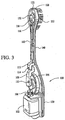
- FIG. 3 illustrates an electric toothbrush 100 comprising a toothbrush head 120, a body or handle 130, and an elongated neck 140 extending therebetween.
- the drive train which includes various shafts and gears that transmit motion from a motor to an inner movable bristle holder 152 is similar to that described in US Patent No. 6,178,579 .
- the handle 130 is hollow and includes a motor 102 and batteries (not shown) for powering the motor.
- a rechargeable power source can be substituted for the batteries.
- the head 120 has a longitudinal axis extending therethrough. The longitudinal axis extends in the same general longitudinal direction as a longitudinal axis of the shaft 160.
- the inner movable bristle holder 152 is disposed along the head 120, wherein the end 122 is at the distal most point of the head 120. Although in one embodiment the inner movable bristle holder 152 is oval in shape, other shapes can be utilized. Further, while the inner movable bristle holder 152 is disposed proximate the end 122 of the head 120, it will be appreciated that the movable bristle holder 152 can be disposed away from the end 122 and other features, such as stationary bristles, can be disposed around at least a portion of the perimeter of the inner movable bristle holder 152. In this embodiment, the inner movable bristle holder 152 reciprocates.
- a first gear 104 is operatively connected to and powered by the motor 102.
- a second gear 106 is operatively connected to the first gear 104.
- the rotational axis of the second gear 106 is approximately normal to the rotational axis of the first gear 104 such that the teeth of the first gear 104 mesh with teeth of the second gear 106, thus causing second gear 106 to rotate as the first gear 104 rotates.
- a first arm 108 is eccentrically and pivotably connected to the second gear 106 via a pin 110 or other fastening device. Due to the eccentric connection, the rotational motion of the second gear 106 is converted into a reciprocating motion of the first arm 108.
- a second arm 112 is pivotably connected to the first arm 108 via a pin 114 or other fastening device.
- the shaft 160 is fixedly secured, such as by a press fit, to the second arm 112.
- the shaft 160 is housed at least partially within the neck 140.
- the shaft 160 is also engaged with a third arm 116.
- the third arm 116 is connected at its terminal end to the inner bristle holder 152 via a pin 118 or other fastening device.
- the terminal end of the third arm 116 is offset from the longitudinal axis of the shaft 160 so that it is pinned adjacent the outer periphery of the inner bristle holder 152.
- This offset arrangement converts the reciprocating motion of the third arm 116 into a reciprocating motion of the inner bristle holder 152, wherein the inner bristle holder 152 reciprocates about an axis approximately parallel to the longitudinal axis of the shaft 160.
- FIG. 1 and 2 illustrate an embodiment of the drive shaft 95 in accordance with the present invention.
- the drive shaft 95 is utilized in the embodiment of the toothbrush depicted in Figures 1 and 2 .
- the drive shaft 95 includes a spring portion, element, or component 96 along at least a portion of its length.
- the spring portion 96 is integrally formed as part of the drive shaft.
- the drive shaft 95 including the spring portion 96 is a one piece unit.
- the drive shaft 160 illustrated in Figure 3 also features a spring portion, element, or component along at least a portion of its length. The description of this spring component is the same as the following description for spring 96 provided with drive shaft 95.
- the specific type of load applied to the spring element during use of the toothbrush may be either compressive or tensile. That is, during normal use of the brush, either a compressive load or a tensile load may be placed upon the spring. Typically, the application of these loads will alternate as the drive shaft reciprocates. For example, after the application of a tensile load, a compressive load is then applied, afterwhich a tensile load is then applied...etc. As previously explained, if an excessive load is placed upon the spring, the spring may be either compressed or extended depending upon whether the load is compressive or tensile.
- the degree to which the spring is compressed or extended depends upon the magnitude of the excessive load, the stroke length and the characteristics of the spring.
- Springs are fundamental mechanical components which form the basis of many mechanical systems.
- a spring can be defined to be an elastic member which exerts a resisting force when its shape is changed.
- the resisting force is not linearly proportional to its displacement.
- the embodiments described herein utilize linear springs.
- the present invention includes the use of non-linear springs.
- a force of between about 1 to about 15 Newtons is an excessive force, and therefore can stall the motor.
- a load of about 1 to about 15 Newtons applied to the head of the toothbrush may translate to a load of about 1 to about 15 Newtons on the drive shaft of the toothbrush depending on the type and manner of connection between the drive shaft and the movable bristle holder.
- one method of choosing a spring constant which can absorb the excess load of a particular motor involves first determining what load will stall the motor.
- the spring constant may be less than about 100%, 90%, 80%, 75%, 65%, and 50% of the maximum spring constant and/or greater than about 25%, 35% 45% and 55% of the minimum spring constant.
- Another embodiment of the present invention utilizes a spring or spring element in a drive shaft, in which the spring exhibits a spring constant of from about 4 to about 8 N/mm, in another embodiment the spring or spring element exhibits a spring constant of from about 5 to about 7 N/mm, and in yet another embodiment the spring constant is about 6 N/mm.
- the present invention includes the use of springs having spring constants greater than, or lesser than these representative values. For example, it is contemplated that springs having a spring constant of greater than about 0.1, 0.5, 1.0, 1.5, 2.0, 2.5, 3.0, 3.5, and 8.5, 9.0, 9.5, 10 N/mm and higher could be utilized in a drive mechanism.
- a proper spring constant is one that corresponds to the spring being displaced at least a portion of the "stroke length" of the drive shaft upon application of an excessive load.
- stroke length refers to the maximum linear distance that the drive shaft travels in one direction during a reciprocation cycle.
- the stroke length of the bristle holder can be from about 0.5 mm to about 3 mm, in another embodiment the stroke length of the bristle holder can be from about 0.75 mm to about 2.0 mm, in another embodiment the stroke length of the bristle holder can be from about 0.75 mm to about 1.0 mm, and in yet another embodiment the stroke length of the bristle holder can be about 0.85 mm.
- springs exhibit a spring constant that is the same or substantially the same regardless of whether the applied load is tensile or compressive
- one type of spring in accordance with the present invention exhibits different spring constants for tensile loads and compressive loads.
- the spring can absorb at least the stroke length of the drive shaft.
- a spring element is incorporated into a drive shaft of a reciprocating drive mechanism.
- the drive shaft during operation of the toothbrush, exhibits a stroke length of about 0.85 mm.
- the material(s) and geometry of the spring are selected such that upon application of an excessive load to the brush head while brushing, the spring is compressed and extended, in each direction by the stroke length. This enables the motor to continue to operate while consuming ordinary levels of power from the battery.
- the material(s) and geometry of the spring are selected such that upon application of loads to the brush head less than those deemed excessive; the spring is not displaced to any appreciable extent. This enables the drive shaft to reciprocate and transfer power without any significant loss in efficiency from its motor end, through and across the spring, to the brushing end of the drive shaft.
- the 3 pound (13,34N) load is applied to the bristle holder as a compressive force on the bristles and thus in turn, on the bristle holder, generally in a direction that is perpendicular to the longitudinal axis of the toothbrush.
- Application of this load increases friction between the reciprocating bristle holder and the surfaces that it contacts.
- the resulting load exhibited at the brushing end of the drive shaft, upon application of the about 3 pound(13,34N) brushing load to the bristle holder, is about 1 pound (4,45N).
- This about 1 pound (4,45N) of force may be considered as the amount of force necessary to overcome the increased friction of the bristle holder resulting from the about 3 pound (13,34N) load placed thereon.
- the about 1 pound of force is generally directed along the longitudinal axis of the reciprocating drive shaft.
- a spring may be formed into a relatively flexible shape using a relatively non-flexible or stiff material.
- the spring may be formed into a relatively non-flexible shape using a relatively flexible material.
- the spring may be formed into a relatively flexible shape using a relatively flexible material.
- the spring may be formed into a relatively non-flexible shape and formed from a relatively non-flexible material. This latter set of characteristics would likely not be preferred due to the very large spring constants resulting therefrom.
- the drive shaft and spring may be formed from a variety of materials.
- the drive shaft and spring are formed from the same material.
- the drive shaft and spring can be formed from a polymeric material that exhibits sufficient strength and rigidity to transfer power from the motor to one or more movable bristle holders disposed on the head of the toothbrush without undergoing significant deformation during normal operations of the toothbrush.
- suitable polymeric materials include, but are not limited to, self-lubricating materials; polymeric materials such as ABS, nylon, PPE, POM (a polyoxymethylene copolymer), and Delrin® acetal resins available from DuPont®; and metals such as steel and aluminum.
- An example of a commercially available nylon is PA6 nylon, available from DuPont.
- the present invention also encompasses embodiments in which the drive shaft and spring portion are formed from different materials, materials differing in their flexibility, rigidity, or other physical properties.
- Fig. 6 illustrates a spring portion 196 formed from a material different than the material forming a drive shaft 195 .
- Fig. 7 illustrates an alternate embodiment drive shaft 295 having a spring portion 296 formed from a material different than the material constituting the drive shaft 295.
- the spring function is provided by appropriate selection of the material forming the spring portion 296 as opposed to that function resulting from the configuration or shape of the portion 296.
- Fig. 8 illustrates yet another alternate embodiment of a drive shaft 395 having a spring portion 396 formed from a different material. Viewing Figs.
- the spring characteristics may be varied by appropriate choice of the shape or configuration of the spring.
- the spring characteristics may be varied by appropriate choice of materials that form the springs.
- the present invention also encompasses spring elements utilized in conjunction with drive mechanisms utilizing a rotary drive shaft.
- a torsional or coil spring could be incorporated along a portion of a rotary drive shaft as previously shown in Fig. 6 .
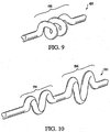
- Fig. 9 illustrates an alternate embodiment drive shaft 495 having a coil spring 496 in which both the coil spring and the drive shaft are formed from the same material.
- the spring 496 would not undergo any significant rotational deformation and so, efficiently transfer rotary power from one end of the drive shaft to the other.
- the spring upon application of an excessive load, the spring would deform, i.e. undergo torsional deformations, to thereby limit or otherwise reduce the load placed upon the motor. This, as described herein, reduces power consumption from the battery.
- the present invention also encompasses the use of two or more springs or spring elements in a drive mechanism of an electric toothbrush.
- the provision of two or more springs enables the drivetrain to be particularly adapted to absorb excessive loads at certain operating conditions, or particular ranges or magnitudes of loads.
- each of the springs may be of a different size, type or configuration; may exhibit a different spring constant; may be formed from different materials; or may be positioned at different locations along the drive mechanism or drive shaft.
- Fig. 10 illustrates an embodiment of the drive shaft 595 comprising a first spring 594 and a second spring 596.
- the springs 594 and 596 exhibit different spring characteristics.
- the drive shaft 595 and the springs 594 and 596 are all formed from the same material. However, due to the size and/or configurational differences between the springs 594 and 596, the two springs have different spring constants.
- the present invention also includes a strategy of forming one or more of the springs from a first material, and forming one or more of the other or remaining springs from a different material.
- the materials selected for forming the springs may also be entirely different than the material constituting the drive shaft.
- Fig. 11 illustrates a drive shaft 695 comprising a first spring 694 and a second spring 696.
- the second spring 696 is formed from a different material than is used for the spring 694.
- the materials selected for the springs 694 and 696 can be selected such that the springs exhibit different spring constants. It is also contemplated to provide a drive shaft with a spring element provided by a region of a different material.
- Fig. 12 illustrates a driveshaft 795 comprising a first spring 794 and a second spring 796.
- the material forming the second spring 796 is different than the material forming the spring 794 and the drive shaft 795.
- Fig. 13 illustrates a drive shaft 895 having multiple springs such as a first spring 894 and a second spring 896, each formed from a different material. It is also contemplated that the remaining portion of the drive shaft 895 is formed from another, different material.
- Fig. 13 also illustrates an aspect in which springs of a similar configuration, however of a different size, are provided on a drive shaft.
- Another aspect included in the present invention is the selective orientation of a drive shaft having multiple springs or spring portions within a drive mechanism.
- the drive shaft having multiple springs may be oriented within the drive train such that a particular spring is first exposed to loads applied to the brushing end of the drive shaft.
- the various springs or spring elements may be disposed on the drive shaft in a particular sequence.
- the present invention includes embodiments in which a spring component is provided separate from the drive shaft.
- a drive mechanism would utilize the spring component at a location between the motor output shaft and the one or more bristle holder(s) that are powered by the motor.
- the embodiments of the toothbrushes described herein utilize a spring element disposed within the neck region of the toothbrush
- the present invention includes embodiments in which the spring is disposed in other regions of the toothbrush.
- the spring could be positioned or generally reside within the handle portion of the toothbrush.
- the spring could be provided in the head region of the toothbrush.
- bristles might be arranged differently to complement-or further enhance the fixed bristles or the motion of the movable bristles.
- Some or all of the bristles might extend in a direction which forms an acute angle with a top surface of a bristle holder, and may extend in a forward or rearward direction.
- some of the bristles might extend outwardly away from the head, in another direction, again forming an acute angle with respect to the top surface of the bristle holder.
- Massaging bristles or bristles of varying height might also be used, such as described in US Patent Nos. Des. 330,286 , and Des. 434,563 .
- Other bristle arrangements suitable for use include those arrangements described in whole or part in US Patent Nos. 6,006,394 ; 4,081,876 ; 5,046,213 ; 5,335,389 ; 5,392,483 ; 5,446,940 ; 4,894,880 ; and International Publication No. WO99/23910 .
- the inventive electric toothbrushes can be made with any combination of bristle or massaging tip types, dimensions, combinations, angles and arrangements.
- Tufts of bristles may alternate in height.
- the difference in length between the tall tufts and the shorter tufts is between about 0.5 mm and about 2.5 mm in one embodiment and between about 1 mm and about 2 mm in other embodiments.
- the tall and short tufts of bristles can be provided with different characteristics.
- the tall tufts of bristles may be relatively soft for gently cleaning and massaging gums of a user while shorter tufts of bristles may be somewhat firmer for interdental cleaning (or vice versa).
- the present invention provides a bristle configuration in which the movable bristles, i.e. those supported by and secured to the movable bristle holder, have a total bristle length that is less than the length of the stationary bristles that at least partially encircle or extend alongside the movable bristle holder and bristles secured thereto.
- a further variation of this bristle configuration features a movable bristle holder that is slightly elevated above the outer surface of the head such that the distal tips of the movable bristles are approximately at the same height as the longer stationary bristles extending from the outer surface of the head.
- the distance or stroke of the movable bristle holder (when undergoing a reciprocating motion) is less than if longer bristles were used.
- a shorter stroke generally leads to decreased power requirements. This is beneficial since battery demands are then reduced, which may further promote manufacturability and commercialability of the resulting toothbrush.
- relatively short length bristles for the movable bristles, and longer bristles for the stationary bristles a greater proportion of the brushing load is assumed by the stationary bristles. This generally further reduces power demands on the motor and drive mechanism of the toothbrush.
- the various reciprocating bristle holders described herein may also utilize a drive mechanism that provides a shaft that rotates.
- other motor and reciprocating or rotating shaft arrangements can be substituted.
- US Patent Nos. 5,226,206 ; 5,524,312 ; 5,383,242 ; 5,465,444 ; 5,504,959 ; 5,836,030 ; 4,845,795 ; 5,404,608 ; 5,359,747 ; and 5,617,601 disclose other motor and reciprocating shaft arrangements that might be suitable.
- the electric toothbrush described herein might be provided with a replaceable head.
- a suitable arrangement which can be adapted to the present invention is disclosed in US 2002 162 180 .
Landscapes
- Health & Medical Sciences (AREA)
- Dentistry (AREA)
- Epidemiology (AREA)
- Life Sciences & Earth Sciences (AREA)
- Animal Behavior & Ethology (AREA)
- General Health & Medical Sciences (AREA)
- Public Health (AREA)
- Veterinary Medicine (AREA)
- Brushes (AREA)
Description
- The present invention relates to the field of toothbrushes, and more particularly, the invention relates to the field of electrically powered toothbrushes.
- Toothbrushes have traditionally utilized one or more groups of bristles that are fixed or otherwise attached to the head or end of the toothbrush. Toothbrushes are also known that utilize movable bristle sets or holders that are mechanically or electrically powered. Typically, an electric motor and a drive mechanism are retained within the body of the toothbrush and are coupled to the movable bristle sets or holders. Upon actuation of the motor and drive mechanism, the bristle holders may undergo a variety of different types of motion. Typically, one or more batteries are also provided within the body of the toothbrush to power the drive mechanism and impart motion to the movable bristle holders.
- During operation of an electric toothbrush, power consumption of the electric motor is generally a function of the rate of rotation and load placed upon the motor by the drive mechanism. These parameters are dependent upon the load placed upon the brushing elements, e.g. the moving bristle holders, disposed on the brush head. It is also known that power consumption of the electric motor is also dependent upon the mechanical strain placed upon the motor, and typically, upon the output shaft of the motor.
- A significant disadvantage in using an electric toothbrush is that after some time period of repeated use, the batteries are exhausted and must be replaced. In addition to the increasingly high cost of batteries, battery replacement is often regarded by consumers as burdensome or annoying. In addition, in certain low cost disposable electric toothbrushes, the batteries may be sealed within the body of the toothbrush and not be suitable for replacement. Accordingly, a need exists for extending battery life and the time period between battery replacement in an electric toothbrush.
- Additionally, a need remains for an improved technique and assembly for increasing battery life in an electric toothbrush, particularly for instances besides those involving excessive strain or bending of a brush head or neck.
- The invention is defined in the independent claims, to which reference should now be made. Advantageous embodiments are set out in the sub claims.
-
US 5504959 ,US 5732432 ,US 5617601 andUS 6381795 all disclose electric toothbrushes in which a shaft is interrupted by a spring arrangement. However, in these prior art documents, the spring is intended to flex in normal operation of the toothbrush. - The present invention may take form in various components and arrangements of components, and in various techniques, methods, or procedures and arrangements of steps. The referenced drawings are only for purposes of illustrating embodiments of the toothbrush according to the present invention, they are not necessarily to scale, and are not to be construed as limiting the present invention.
- It is believed that the present invention will be better understood from the following description taken in conjunction with the accompanying drawings in which:
-
Fig. 1 is a perspective view of a toothbrush in accordance with the present invention. -
Fig. 2 is a partial fragmentary perspective view of the toothbrush, illustrated inFig. 1 . -
Fig. 3 is a perspective view showing a partial assembly of another toothbrush in accordance with the present invention. -
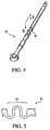
Fig. 4 is a perspective view of a drive shaft in accordance with the present invention. -
Fig. 5 is a detailed, partial side view of a spring portion of the drive shaft shown inFig. 4 . -
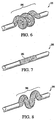
Fig. 6 is a detailed partial perspective view of an alternate drive shaft and spring portion in accordance with the present invention. -
Fig. 7 is a detailed partial perspective view of an alternate drive shaft and spring portion in accordance with the present invention. -
Fig. 8 is a detailed partial perspective view of an alternate embodiment drive shaft and spring portion in accordance with the present invention. -
Fig. 9 is a detailed partial perspective view of an alternate drive shaft and spring portion in accordance with the present invention. -
Fig. 10 is a detailed partial perspective view of an alternate drive shaft and spring portions in accordance with the present invention. -
Fig. 11 is a detailed partial perspective view of an alternate drive shaft and spring portions in accordance with the present invention. -
Fig. 12 is a detailed partial perspective view of an alternate drive shaft and spring portions in accordance with the present invention. -
Fig. 13 is a detailed partial perspective view of an alternate drive shaft and spring portions in accordance with the present invention. - In accordance with the present invention, it has been discovered that battery life in an electric toothbrush can be significantly extended if the load placed upon an electric motor in the toothbrush is regulated. For example, application of an excessive load that stalls or substantially stalls the motor, may consume excessive power. The present invention provides a drive mechanism component, or components, that can limit the load that is applied to the electric motor and prevents stalling by absorbing this excess load, and thereby extends battery life. In the embodiments described herein, these components are springs or spring elements that are provided along a portion of a drive shaft in the drive mechanism. When choosing a spring element the spring constant can be considered. Choosing a spring constant that results in a toothbrush drive shaft that is too flexible can result in insufficient cleaning force applied to the teeth. However, choosing a spring constant that results in a drive shaft that is too rigid, can result in the spring element not absorbing the excessive load, thereby transmitting this load to the motor and failing to prevent the motor from stalling.
- As noted, application of an excessive load to the brush head can consume inordinate or excessive amounts of power from one or more batteries used to power the toothbrush. Generally, an "excessive load," as that term is used herein, is one that when applied to the drive shaft of the toothbrush, results in substantial stalling of the motor. This stalling of the motor results in a reduction in the rate of movement of the movable bristle holder by about 50% to less than about 100%, and typically by about 75% to about 95% and can result in shortened battery life. For example, in one embodiment a toothbrush exhibits a brushing rate, without application of any load to the brush head, of about 250 to about 5000 stroke cycles per minute, in another embodiment the toothbrush exhibits a brushing rate of from about 750 to about 2000 strokes per minute, and in yet another embodiment the toothbrush exhibits a brushing rate of about 1250 strokes per minute. A "stroke" as used herein, is one complete cycle of movement. For a reciprocating drive shaft, a stroke includes travel in a first direction and then travel in a second, opposite direction. Upon brushing or application of a normal or typical brushing load to the bristle holders, the brushing rate can decrease to about 625 strokes per minute for a toothbrush exhibiting a brushing rate of about 1250 strokes per minute. However, upon application of greater brushing loads, the brushing rate further decreases. In the present example, the brushing load would be deemed as "excessive" when the rate slowed to about 315 strokes per minute (corresponding to a 75% reduction in brushing rate).
- The spring portion is formed or otherwise provided along a portion of the length of the drive shaft such that during operation of the toothbrush and upon application of an excessive load to the brushing end of the drive shaft, the spring is displaced thereby absorbing a portion of the load. This in turn reduces the expression or transmission of the otherwise excessive load at the other end of the drive shaft, i.e. the motor end of the drive shaft. The term "brushing end" of the drive shaft refers to the end of the drive shaft that is proximate the movable bristle holder driven by the drive shaft and is operatively connected to the holder. And, the term "motor end" of the drive shaft refers to the end of the drive shaft that is proximate the electric motor that ultimately drives the drive shaft. As previously described, it is the application of an excessive load upon the motor that results in excessive power consumption. And so, by reducing or avoiding the application of excessive loads upon the motor, i.e. by provision of the spring portion, excessive power consumption is avoided.
- The spring portion is formed or otherwise provided along a portion of the drive shaft such that during normal use of the toothbrush, and without an excessive load being placed thereon, the spring is not displaced, nor displaced to any significant extent. This characteristic of the spring, during normal operation of the toothbrush, is also described as the spring remaining essentially rigid and unchanged in shape.
-
Fig. 1 is a perspective view of an embodiment of thetoothbrush 10 in accordance with the present invention. Thetoothbrush 10 comprises abody 80, ahead 20, and aneck 40 extending between the handle orbody 80 and thehead 20. An actuator 70 or switch is provided along thebody 80. Disposed on thehead 20 are a plurality of fixedbristles 60 and a collection ofmovable bristles 50, both of which are described and illustrated in detail by the various patents. -
Fig. 2 is a partial fragmentary view of an embodiment of thetoothbrush 10 shown inFig. 1 .Fig. 2 illustrates amotor 90 and a drive train or mechanism retained within thebody 80 that are used to move the collection ofmovable bristles 50 disposed on thebrush head 20. The movable bristles are attached to and supported by a movable bristle holder (not shown inFig. 2 ). Upon activation of actuator 70 (shown inFig. 1 ) disposed along thebody 80 of thetoothbrush 10, electrical energy such as from one or more batteries 75 in thehousing 80, is directed to amotor 90. Themotor 90 includes anoutput shaft 91 to which is affixed adrive gear 92. Thedrive gear 92 is engaged with arotatable drive gear 93. Thedrive gear 93 is mounted such that it rotates about an axis A extending in a direction perpendicular to theoutput shaft 91 of the motor. Thedrive gear 93 includes adrive member 94 which is disposed on thedrive gear 93 radially outward from the center of rotation, or axis A, of thedrive gear 93. Attached to thedrive member 94 is adrive shaft 95. This arrangement of drive components imparts reciprocating motion to thedrive shaft 95 from a poweredrotary output shaft 91. - A wide array of drive motor and gearing configurations may be utilized in the toothbrushes described herein. For example, various drive mechanisms described in
U.S. Patents 6,178,579 ;6,189,693 ;6,360,395 ; and6,371,294 , may be utilized. - As will be appreciated, the movable bristles are disposed and generally supported on one or more movable bristle holders. The movable bristle holder may undergo a wide variety of motions. The movable bristle holder may undergo angular motion, linear motion, or curvilinear motion. The movement of the bristle holder may be constant or periodic. In one embodiment, the motion of the movable bristle holder is periodic linear motion or reciprocation.
- Another embodiment of the toothbrush using a reciprocating drive shaft is illustrated in
Fig. 3. Fig. 3 illustrates anelectric toothbrush 100 comprising atoothbrush head 120, a body or handle 130, and anelongated neck 140 extending therebetween. The drive train, which includes various shafts and gears that transmit motion from a motor to an inner movable bristleholder 152 is similar to that described inUS Patent No. 6,178,579 . Thehandle 130 is hollow and includes amotor 102 and batteries (not shown) for powering the motor. A rechargeable power source can be substituted for the batteries. Thehead 120 has a longitudinal axis extending therethrough. The longitudinal axis extends in the same general longitudinal direction as a longitudinal axis of theshaft 160. The inner movable bristleholder 152 is disposed along thehead 120, wherein theend 122 is at the distal most point of thehead 120. Although in one embodiment the inner movable bristleholder 152 is oval in shape, other shapes can be utilized. Further, while the inner movable bristleholder 152 is disposed proximate theend 122 of thehead 120, it will be appreciated that the movable bristleholder 152 can be disposed away from theend 122 and other features, such as stationary bristles, can be disposed around at least a portion of the perimeter of the inner movable bristleholder 152. In this embodiment, the inner movable bristleholder 152 reciprocates. - A
first gear 104 is operatively connected to and powered by themotor 102. A second gear 106 is operatively connected to thefirst gear 104. The rotational axis of the second gear 106 is approximately normal to the rotational axis of thefirst gear 104 such that the teeth of thefirst gear 104 mesh with teeth of the second gear 106, thus causing second gear 106 to rotate as thefirst gear 104 rotates. - A
first arm 108 is eccentrically and pivotably connected to the second gear 106 via apin 110 or other fastening device. Due to the eccentric connection, the rotational motion of the second gear 106 is converted into a reciprocating motion of thefirst arm 108. Asecond arm 112 is pivotably connected to thefirst arm 108 via apin 114 or other fastening device. Theshaft 160 is fixedly secured, such as by a press fit, to thesecond arm 112. Theshaft 160 is housed at least partially within theneck 140. Theshaft 160 is also engaged with athird arm 116. Thethird arm 116 is connected at its terminal end to the inner bristleholder 152 via apin 118 or other fastening device. The terminal end of thethird arm 116 is offset from the longitudinal axis of theshaft 160 so that it is pinned adjacent the outer periphery of the inner bristleholder 152. This offset arrangement converts the reciprocating motion of thethird arm 116 into a reciprocating motion of the inner bristleholder 152, wherein the inner bristleholder 152 reciprocates about an axis approximately parallel to the longitudinal axis of theshaft 160. - Both embodiments of the drive mechanisms illustrated in
Figures 2 and3 utilize a drive shaft having a spring component or spring element provided along at least a portion of the drive shaft. More specifically,Figures 4 and 5 illustrate an embodiment of thedrive shaft 95 in accordance with the present invention. Thedrive shaft 95 is utilized in the embodiment of the toothbrush depicted inFigures 1 and2 . Thedrive shaft 95 includes a spring portion, element, orcomponent 96 along at least a portion of its length. In one embodiment thespring portion 96 is integrally formed as part of the drive shaft. In another embodiment thedrive shaft 95 including thespring portion 96 is a one piece unit. Thedrive shaft 160 illustrated inFigure 3 also features a spring portion, element, or component along at least a portion of its length. The description of this spring component is the same as the following description forspring 96 provided withdrive shaft 95. - The specific type of load applied to the spring element during use of the toothbrush may be either compressive or tensile. That is, during normal use of the brush, either a compressive load or a tensile load may be placed upon the spring. Typically, the application of these loads will alternate as the drive shaft reciprocates. For example, after the application of a tensile load, a compressive load is then applied, afterwhich a tensile load is then applied...etc. As previously explained, if an excessive load is placed upon the spring, the spring may be either compressed or extended depending upon whether the load is compressive or tensile.
- The degree to which the spring is compressed or extended, depends upon the magnitude of the excessive load, the stroke length and the characteristics of the spring. Before describing these aspects in greater detail, it is instructive to consider springs, their characteristics, and behavior.
- Springs are fundamental mechanical components which form the basis of many mechanical systems. A spring can be defined to be an elastic member which exerts a resisting force when its shape is changed. Most springs are assumed linear and obey Hooke's Law:

- For a non-linear spring, the resisting force is not linearly proportional to its displacement. The embodiments described herein utilize linear springs. However, the present invention includes the use of non-linear springs.
- To choose a spring constant the motor and the structural arrangement of the motor and drive shaft can be considered. Although, other forces can be considered depending on the characteristics of the motor, generally a force of between about 1 to about 15 Newtons is an excessive force, and therefore can stall the motor. A load of about 1 to about 15 Newtons applied to the head of the toothbrush may translate to a load of about 1 to about 15 Newtons on the drive shaft of the toothbrush depending on the type and manner of connection between the drive shaft and the movable bristle holder. On account of the variety of motors available, one method of choosing a spring constant which can absorb the excess load of a particular motor involves first determining what load will stall the motor. To determine this load in a toothbrush having a reciprocating shaft, one can attach a drive shaft to the motor and apply load to the drive shaft until the motor stalls. This is the maximum load required to stall the motor. This load in combination with the stroke length can then be used to calculate the maximum desired spring constant. The maximum desired spring constant will only flex to absorb the stroke length of the movable bristle holder when the load has reached the level required to stall the motor. The minimum desired spring constant is based upon the load necessary to get desired mouth feel and cleaning capabilities. The closer the spring constant is to the minimum desired spring constant the less of a load is required to result in flexing of the spring element of the drive shaft. However, this likely results in minimized cleaning capabilities, as the spring absorbs all load originating from the motor, and no movement of the drive shaft is translated to the movable bristle holder on the head of the toothbrush. Additionally, the extension of battery life is diminished the closer the spring constant is to the maximum desired spring constant as the spring element will not absorb any excess load until the maximum load to stall the motor is reached. In one embodiment the spring constant may be less than about 100%, 90%, 80%, 75%, 65%, and 50% of the maximum spring constant and/or greater than about 25%, 35% 45% and 55% of the minimum spring constant.
- Another embodiment of the present invention utilizes a spring or spring element in a drive shaft, in which the spring exhibits a spring constant of from about 4 to about 8 N/mm, in another embodiment the spring or spring element exhibits a spring constant of from about 5 to about 7 N/mm, and in yet another embodiment the spring constant is about 6 N/mm. It will be understood however that the present invention includes the use of springs having spring constants greater than, or lesser than these representative values. For example, it is contemplated that springs having a spring constant of greater than about 0.1, 0.5, 1.0, 1.5, 2.0, 2.5, 3.0, 3.5, and 8.5, 9.0, 9.5, 10 N/mm and higher could be utilized in a drive mechanism.
- Utilizing a spring having a spring constant of 4 N/mm will result in the following approximate relationships set forth in Table 1 between force applied at the brushing end of the drive shaft and the displacement of the spring.
Table 1 Relationship Between Applied Force and Spring Displacement for k = 4 N/mm Force (F) Displacement (Δ) 1 N 0.25 mm 2 0.50 3 0.75 4 1.00 5 1.25 6 1.50 7 1.75 8 2.00 9 2.20 10 2.50 - Utilizing a spring having a spring constant of 5 N/mm will result in the following approximate relationships set forth in Table 2 between force applied at the brushing end of the drive shaft and the displacement of the spring.
Table 2 Relationship Between Applied Force and Spring Displacement for k = 5 N/mm Force (F) Displacement (Δ) 1 N 0.20 mm 2 0.40 3 0.60 4 0.80 5 1.00 6 1.20 7 1.40 8 1.60 9 1.80 10 2.00 - And, utilizing a spring having a spring constant of 6 N/mm, leads to the following relationship between force and spring displacement, as shown in Table 3.
Table 3 Relationship Between Applied Force and Spring Displacement for k = 6 N/mm Force (F) Displacement (Δ) 1 N 0.17 mm 2 0.33 3 0.50 4 0.67 5 0.80 6 1.00 7 1.17 8 1.33 9 1.50 10 1.67 - Utilizing a spring having a spring constant of 7 N/mm will result in the following approximate relationships set forth in Table 4 between force applied at the brushing end of the drive shaft and the displacement of the spring.
Table 4 Relationship Between Applied Force and Spring Displacement for k = 7 N/mm Force (F) Displacement (Δ) 1 N 0.14 mm 2 0.29 3 0.43 4 0.57 5 0.72 6 0.86 7 1.00 8 1.14 9 1.29 10 1.43 - Utilizing a spring having a spring constant of 8 N/mm will result in the following approximate relationships set forth in Table 5 between force applied at the brushing end of the drive shaft and the displacement of the spring.
Table 5 Relationship Between Applied Force and Spring Displacement for k = 8 N/mm Force (F) Displacement (Δ) 1 N 0.13 mm 2 0.25 3 0.38 4 0.50 5 0.63 6 0.75 7 0.88 8 1.00 9 1.13 10 1.25 - In accordance with the present invention, various approaches are provided for designing a spring element for a reciprocating drive shaft. That is, by selection of a suitable material for the spring and appropriate design of the shape or configuration of the spring, a proper spring constant can be achieved. A proper spring constant is one that corresponds to the spring being displaced at least a portion of the "stroke length" of the drive shaft upon application of an excessive load. The term "stroke length" as used herein refers to the maximum linear distance that the drive shaft travels in one direction during a reciprocation cycle. In one embodiment of the toothbrush the stroke length of the bristle holder can be from about 0.5 mm to about 3 mm, in another embodiment the stroke length of the bristle holder can be from about 0.75 mm to about 2.0 mm, in another embodiment the stroke length of the bristle holder can be from about 0.75 mm to about 1.0 mm, and in yet another embodiment the stroke length of the bristle holder can be about 0.85 mm.
- Although many springs exhibit a spring constant that is the same or substantially the same regardless of whether the applied load is tensile or compressive, one type of spring in accordance with the present invention exhibits different spring constants for tensile loads and compressive loads. In one embodiment the spring can absorb at least the stroke length of the drive shaft.
- Testing was performed in which the resulting spring displacement from application of an excessive load to a spring element according to the present invention was investigated. In that testing, one end of the spring was fixed, and the other opposite end received a particular force. For a maximum excessive tensile force of about -1.4 pounds (-6.23 N), the spring was extended by about 0.85 mm. And, for a maximum excessive compressive force of about 0.95 pounds (4.23 N), the spring was compressed by about 0.80 mm. The amount of force as measured at the drive shaft corresponding to these excessive loads is about 1.2 ± 0.30 pounds (5.34 ± 1.33 Newtons) of force. Calculating a spring constant k from these values of displacement and force, results in k = 6.28 ± 1.56 N/mm.
- In one exemplary embodiment according to the present invention, a spring element is incorporated into a drive shaft of a reciprocating drive mechanism. The drive shaft, during operation of the toothbrush, exhibits a stroke length of about 0.85 mm. The material(s) and geometry of the spring are selected such that upon application of an excessive load to the brush head while brushing, the spring is compressed and extended, in each direction by the stroke length. This enables the motor to continue to operate while consuming ordinary levels of power from the battery. And, furthermore, the material(s) and geometry of the spring are selected such that upon application of loads to the brush head less than those deemed excessive; the spring is not displaced to any appreciable extent. This enables the drive shaft to reciprocate and transfer power without any significant loss in efficiency from its motor end, through and across the spring, to the brushing end of the drive shaft.
- Although not wishing to be limited to any particular theory or design approach, an approximate relationship has been identified between excessive brushing loads as measured on a bristle holder in one embodiment of a brush head, and that load as expressed at the brushing end of the drive shaft. Generally, in that particular electric toothbrush embodiment utilizing a reciprocating drive mechanism that powers a movable bristle holder, application of a brushing load of about 3 pounds (13,34N) on the bristle holder corresponds to a load of about 1 pound (4,45N) as measured at the brushing end of a drive shaft. The 3 pound (13,34N) load is applied to the bristle holder as a compressive force on the bristles and thus in turn, on the bristle holder, generally in a direction that is perpendicular to the longitudinal axis of the toothbrush. Application of this load increases friction between the reciprocating bristle holder and the surfaces that it contacts. The resulting load exhibited at the brushing end of the drive shaft, upon application of the about 3 pound(13,34N) brushing load to the bristle holder, is about 1 pound (4,45N). This about 1 pound (4,45N) of force may be considered as the amount of force necessary to overcome the increased friction of the bristle holder resulting from the about 3 pound (13,34N) load placed thereon. The about 1 pound of force is generally directed along the longitudinal axis of the reciprocating drive shaft.
- The characteristics and behavior of springs are generally dependent upon the material from which the spring is formed, and the geometry, e.g. shape or configuration, of the spring. In order to provide a suitable spring portion in a drive shaft according to the present invention, a spring may be formed into a relatively flexible shape using a relatively non-flexible or stiff material. Alternatively, the spring may be formed into a relatively non-flexible shape using a relatively flexible material. And, the spring may be formed into a relatively flexible shape using a relatively flexible material. Moreover, the spring may be formed into a relatively non-flexible shape and formed from a relatively non-flexible material. This latter set of characteristics would likely not be preferred due to the very large spring constants resulting therefrom.
- Specifically, the drive shaft and spring may be formed from a variety of materials. In one embodiment, the drive shaft and spring are formed from the same material. The drive shaft and spring can be formed from a polymeric material that exhibits sufficient strength and rigidity to transfer power from the motor to one or more movable bristle holders disposed on the head of the toothbrush without undergoing significant deformation during normal operations of the toothbrush. Examples of suitable polymeric materials include, but are not limited to, self-lubricating materials; polymeric materials such as ABS, nylon, PPE, POM (a polyoxymethylene copolymer), and Delrin® acetal resins available from DuPont®; and metals such as steel and aluminum. An example of a commercially available nylon is PA6 nylon, available from DuPont. It is also contemplated to utilize other materials for forming the drive shaft and spring. Examples of materials that can be utilized in the inventive toothbrush include, but are not limited to, those discussed in
US 2004 128780 . Furthermore, it may be desirable to provide a low friction coating on the exterior surface of the drive shaft and/or the spring to minimize friction between that component and the interior walls of the cavity defined within the neck. - The present invention also encompasses embodiments in which the drive shaft and spring portion are formed from different materials, materials differing in their flexibility, rigidity, or other physical properties.
Fig. 6 illustrates aspring portion 196 formed from a material different than the material forming adrive shaft 195.Fig. 7 illustrates an alternateembodiment drive shaft 295 having aspring portion 296 formed from a material different than the material constituting thedrive shaft 295. In this embodiment, it will be appreciated that the spring function is provided by appropriate selection of the material forming thespring portion 296 as opposed to that function resulting from the configuration or shape of theportion 296.Fig. 8 illustrates yet another alternate embodiment of adrive shaft 395 having aspring portion 396 formed from a different material. ViewingFigs. 7 and 8 collectively, it will be appreciated for example, that in the event that the materials forming springs are the same, the spring characteristics may be varied by appropriate choice of the shape or configuration of the spring. Furthermore, in the event that the shape or configuration of the springs is the same, the spring characteristics may be varied by appropriate choice of materials that form the springs. - The present invention also encompasses spring elements utilized in conjunction with drive mechanisms utilizing a rotary drive shaft. For example, a torsional or coil spring could be incorporated along a portion of a rotary drive shaft as previously shown in
Fig. 6 .Fig. 9 illustrates an alternateembodiment drive shaft 495 having acoil spring 496 in which both the coil spring and the drive shaft are formed from the same material. During normal operation of the toothbrush, thespring 496 would not undergo any significant rotational deformation and so, efficiently transfer rotary power from one end of the drive shaft to the other. However, upon application of an excessive load, the spring would deform, i.e. undergo torsional deformations, to thereby limit or otherwise reduce the load placed upon the motor. This, as described herein, reduces power consumption from the battery. - The present invention also encompasses the use of two or more springs or spring elements in a drive mechanism of an electric toothbrush. The provision of two or more springs enables the drivetrain to be particularly adapted to absorb excessive loads at certain operating conditions, or particular ranges or magnitudes of loads. Moreover, each of the springs may be of a different size, type or configuration; may exhibit a different spring constant; may be formed from different materials; or may be positioned at different locations along the drive mechanism or drive shaft. For example,
Fig. 10 illustrates an embodiment of thedrive shaft 595 comprising afirst spring 594 and asecond spring 596. Thesprings Fig. 10 , thedrive shaft 595 and thesprings springs - For a drive shaft comprising multiple springs or spring elements, the present invention also includes a strategy of forming one or more of the springs from a first material, and forming one or more of the other or remaining springs from a different material. Again, the materials selected for forming the springs may also be entirely different than the material constituting the drive shaft.
Fig. 11 illustrates adrive shaft 695 comprising afirst spring 694 and asecond spring 696. Thesecond spring 696 is formed from a different material than is used for thespring 694. As will be appreciated, generally, the materials selected for thesprings Fig. 12 illustrates adriveshaft 795 comprising afirst spring 794 and asecond spring 796. The material forming thesecond spring 796 is different than the material forming thespring 794 and thedrive shaft 795.Fig. 13 illustrates adrive shaft 895 having multiple springs such as afirst spring 894 and asecond spring 896, each formed from a different material. It is also contemplated that the remaining portion of thedrive shaft 895 is formed from another, different material.Fig. 13 also illustrates an aspect in which springs of a similar configuration, however of a different size, are provided on a drive shaft. - Another aspect included in the present invention is the selective orientation of a drive shaft having multiple springs or spring portions within a drive mechanism. Generally, depending upon the particular application, the drive shaft having multiple springs may be oriented within the drive train such that a particular spring is first exposed to loads applied to the brushing end of the drive shaft. Similarly, the various springs or spring elements may be disposed on the drive shaft in a particular sequence.
- Although the embodiments described herein utilize spring portions or spring elements that are integrally provided as part of a drive shaft, the present invention includes embodiments in which a spring component is provided separate from the drive shaft. In such a configuration, a drive mechanism would utilize the spring component at a location between the motor output shaft and the one or more bristle holder(s) that are powered by the motor.
- Moreover, although the embodiments of the toothbrushes described herein utilize a spring element disposed within the neck region of the toothbrush, the present invention includes embodiments in which the spring is disposed in other regions of the toothbrush. For example, the spring could be positioned or generally reside within the handle portion of the toothbrush. And, the spring could be provided in the head region of the toothbrush.
- While brush heads of embodiments of the toothbrush have been illustrated for simplicity with tufts of bristles that extend in a direction substantially perpendicular to the longitudinal axis of the head from which they extend, it is contemplated that the bristles might be arranged differently to complement-or further enhance the fixed bristles or the motion of the movable bristles. Some or all of the bristles might extend in a direction which forms an acute angle with a top surface of a bristle holder, and may extend in a forward or rearward direction. In another embodiment, some of the bristles might extend outwardly away from the head, in another direction, again forming an acute angle with respect to the top surface of the bristle holder. Massaging bristles or bristles of varying height might also be used, such as described in
US Patent Nos. Des. 330,286 , and Des.434,563 . Other bristle arrangements suitable for use include those arrangements described in whole or part inUS Patent Nos. 6,006,394 ;4,081,876 ;5,046,213 ;5,335,389 ;5,392,483 ;5,446,940 ;4,894,880 ; and International Publication No.WO99/23910 - The inventive electric toothbrushes can be made with any combination of bristle or massaging tip types, dimensions, combinations, angles and arrangements. Tufts of bristles may alternate in height. In one embodiment there are a plurality of tall tufts and a plurality of shorter tufts. The difference in length between the tall tufts and the shorter tufts is between about 0.5 mm and about 2.5 mm in one embodiment and between about 1 mm and about 2 mm in other embodiments. The tall and short tufts of bristles can be provided with different characteristics. For example, the tall tufts of bristles may be relatively soft for gently cleaning and massaging gums of a user while shorter tufts of bristles may be somewhat firmer for interdental cleaning (or vice versa). This arrangement allows the longer (and typically softer) bristles to be pressed, bent and deflected against the gums of the user before the shorter (and typically firmer) bristles contact the teeth and gums of the user. Therefore, for example, soft bristles can be applied with more force while stiffer (and perhaps less comfortable) bristles are applied with less force.
- In one embodiment, the present invention provides a bristle configuration in which the movable bristles, i.e. those supported by and secured to the movable bristle holder, have a total bristle length that is less than the length of the stationary bristles that at least partially encircle or extend alongside the movable bristle holder and bristles secured thereto. A further variation of this bristle configuration features a movable bristle holder that is slightly elevated above the outer surface of the head such that the distal tips of the movable bristles are approximately at the same height as the longer stationary bristles extending from the outer surface of the head. Generally, by utilizing movable bristles that have a relatively short length, the distance or stroke of the movable bristle holder (when undergoing a reciprocating motion) is less than if longer bristles were used. A shorter stroke generally leads to decreased power requirements. This is beneficial since battery demands are then reduced, which may further promote manufacturability and commercialability of the resulting toothbrush. Moreover, by utilizing relatively short length bristles for the movable bristles, and longer bristles for the stationary bristles, a greater proportion of the brushing load is assumed by the stationary bristles. This generally further reduces power demands on the motor and drive mechanism of the toothbrush.
- As noted, the various reciprocating bristle holders described herein may also utilize a drive mechanism that provides a shaft that rotates. Furthermore, it will be appreciated that other motor and reciprocating or rotating shaft arrangements can be substituted. For example,
US Patent Nos. 5,226,206 ;5,524,312 ;5,383,242 ;5,465,444 ;5,504,959 ;5,836,030 ;4,845,795 ;5,404,608 ;5,359,747 ; and5,617,601 , disclose other motor and reciprocating shaft arrangements that might be suitable. In addition, the electric toothbrush described herein might be provided with a replaceable head. A suitable arrangement which can be adapted to the present invention is disclosed inUS 2002 162 180 . Similarly, the drive mechanisms disclosed inUS 20030854526 and inUS 2003084527 are also contemplated for use in conjunction with the present invention. Furthermore,U.S. published patent application 2003/0226223 , Serial No.10/274,700 filed on October 21, 2002 - The present invention has been described with reference to particular embodiments. Modifications and alterations will occur to others upon reading and understanding this specification. Furthermore, although certain arrangements for the fixed and movable bristles and various drive mechanisms have been shown and described, the present invention includes a variety of other configurations. It is intended that all such modifications and alterations are included insofar as they come within the scope of the appended claims.
Claims (10)
- An electric toothbrush (10, 100) comprising:a handle (80, 130) defining a hollow interior region with a motor (90, 102) disposed therein;a head (20, 120) comprising a movable bristle holder (152), wherein said movable bristle holder has bristles disposed thereon;a neck (40, 140) extending between said handle and said head; anda drive shaft (95, 160, 195, 295, 395, 495, 595, 695, 795, 895) defining a longitudinal axis, whereinsaid drive shaft extends through said neck and operatively connects said motor to said movable bristle holder for transferring power from said motor to said movable bristle holder, wherein
upon operation of said motor, said drive shaft undergoes reciprocating motion, and wherein
said drive shaft comprises at least one spring element (96, 196, 296, 396, 496, 594, 596, 694, 696, 794, 796, 894, 896) integrally formed with said drive shaft between said motor and said movable bristle holder, said at least one spring element being substantially rigid and unchanged in shape when said drive shaft adjacent said movable bristle holder is not excessively loaded to transfer power from said motor to said drive shaft adjacent said movable bristle holder without any significant loss in efficiency and relatively flexible upon application of an excessive load to said drive shaft adjacent said movable bristle holder which limits movement thereof so that said motor causes said at least one spring element to undergo repeated displacements by absorbing at least some of the power from said motor which enables said motor to continue to operate while consuming ordinary levels of power even though said drive shaft adjacent said movable bristle holder is excessively loaded and has its movement limited, further wherein
the excessive load is a load which would result in substantial stalling of said motor if said at least one spring element was not present on said drive shaft. - The electric toothbrush of claim 1, wherein said at least one spring element and said drive shaft are formed from the same material.
- The electric toothbrush of claim 1, wherein said at least one spring element and said drive shaft are formed from different materials.
- The electric toothbrush of claim 1, wherein said at least one spring element is a linear spring.
- The electric toothbrush of claim 1, wherein said at least one spring element comprises a first spring element and a second spring element.
- The electric toothbrush of claim 5, wherein said first spring element exhibits a spring constant different than a spring constant of said second spring element.
- The electric toothbrush of claim 5, wherein said first spring element is formed from a material different than that forming said second spring element.
- The electric toothbrush of claim 1, wherein said substantial stalling of said motor results in a reduction in the rate of movement of said movable bristle holder by about 50 percent to less than about 100 percent.
- The electric toothbrush of claim 8, wherein the reduction in the rate of movement of said movable bristle holder is about 75 percent to 95 percent.
- The electric toothbrush according to any of the preceding claims, wherein the moveable bristle holder is mounted for relative movement on said head.
Applications Claiming Priority (2)
| Application Number | Priority Date | Filing Date | Title |
|---|---|---|---|
| US54532504P | 2004-02-17 | 2004-02-17 | |
| PCT/US2005/005112 WO2005079624A2 (en) | 2004-02-17 | 2005-02-17 | Electric toothbrush having a flexible drive shaft |
Publications (2)
| Publication Number | Publication Date |
|---|---|
| EP1720426A2 EP1720426A2 (en) | 2006-11-15 |
| EP1720426B1 true EP1720426B1 (en) | 2016-09-07 |
Family
ID=34886134
Family Applications (1)
| Application Number | Title | Priority Date | Filing Date |
|---|---|---|---|
| EP05723235.7A Not-in-force EP1720426B1 (en) | 2004-02-17 | 2005-02-17 | Electric toothbrush having a flexible drive shaft |
Country Status (9)
| Country | Link |
|---|---|
| US (1) | US7398575B2 (en) |
| EP (1) | EP1720426B1 (en) |
| JP (1) | JP4533901B2 (en) |
| KR (1) | KR101255859B1 (en) |
| CN (1) | CN1933789B (en) |
| CA (1) | CA2556449C (en) |
| MX (1) | MXPA06009408A (en) |
| RU (1) | RU2373895C2 (en) |
| WO (1) | WO2005079624A2 (en) |
Families Citing this family (16)
| Publication number | Priority date | Publication date | Assignee | Title |
|---|---|---|---|---|
| US7861348B2 (en) | 2004-12-08 | 2011-01-04 | The Procter & Gamble Company | Electric toothbrushes |
| DE102006004146A1 (en) * | 2006-01-27 | 2007-08-02 | Braun Gmbh | Electric toothbrush hand part e.g. for electric toothbrush, has housing, drive which is resiliently mounted on housing by spring and oscillates in plane of movement such as transversely to longitudinal axis of toothbrush |
| WO2010001196A1 (en) * | 2008-07-02 | 2010-01-07 | Koninklijke Philips Electronics N.V. | V-spring configuration and end attachment assemblies therefor for use in a personal care appliance |
| RU2550433C2 (en) * | 2009-12-23 | 2015-05-10 | Конинклейке Филипс Электроникс Н.В. | Mechanically driven resonance driving circuit for electric toothbrush |
| US9750587B2 (en) * | 2012-08-31 | 2017-09-05 | Koninklijke Philips N.V. | Power toothbrush with a tunable brushhead assembly system |
| WO2015069219A1 (en) | 2013-11-05 | 2015-05-14 | Colgate-Palmolive Company | Oral care implement |
| CN105792700B (en) | 2013-11-05 | 2018-09-25 | 高露洁-棕榄公司 | Oral care implement |
| USD751295S1 (en) | 2013-11-05 | 2016-03-15 | Colgate-Palmolive Company | Oral care implement |
| USD749855S1 (en) | 2013-11-05 | 2016-02-23 | Colgate-Palmolive Company | Oral care implement |
| USD764804S1 (en) | 2013-11-05 | 2016-08-30 | Colgate-Palmolive Company | Oral care implement |
| WO2015069221A1 (en) | 2013-11-05 | 2015-05-14 | Colgate-Palmolive Company | Oral care implement |
| DK2942032T3 (en) * | 2014-05-07 | 2017-01-09 | Braun Gmbh | Oral care implement |
| US11173021B2 (en) | 2016-11-03 | 2021-11-16 | Mihran Papazian | Replacement head assembly for toothbrushing systems |
| KR102041499B1 (en) * | 2019-05-27 | 2019-11-06 | 김윤호 | Electric Toothbrush |
| RU2731522C1 (en) * | 2020-03-19 | 2020-09-03 | Андрей Владимирович Ремянников | Toothbrush |
| WO2023068831A1 (en) * | 2021-10-20 | 2023-04-27 | 주식회사 아이투씨브릿지 | Brushing guide elastic toothbrush and elastic restoration mechanism |
Family Cites Families (33)
| Publication number | Priority date | Publication date | Assignee | Title |
|---|---|---|---|---|
| US3757375A (en) * | 1971-08-18 | 1973-09-11 | M Strom | Obstruction removal apparatus |
| GB1570388A (en) | 1975-11-21 | 1980-07-02 | Unilever Ltd | Toothbrushes |
| US4845795A (en) | 1985-06-10 | 1989-07-11 | Dental Research Corporation | Automatic cleaning device |
| JPH0683714B2 (en) * | 1985-09-09 | 1994-10-26 | 松下電工株式会社 | electric toothbrush |
| US4894880A (en) | 1989-02-03 | 1990-01-23 | Aznavoorian Martin P | Tooth brush |
| US5046213A (en) | 1990-03-29 | 1991-09-10 | Colgate-Palmolive Company | Plaque removing toothbrush |
| USD330286S (en) | 1990-03-29 | 1992-10-20 | Colgate-Palmolive Company | Set of bristles for a toothbrush |
| AU647782B2 (en) | 1990-03-29 | 1994-03-31 | Colgate-Palmolive Company, The | Toothbrush |
| US5335389A (en) | 1990-03-29 | 1994-08-09 | Colgate-Palmolive Company | Plaque removing toothbrush |
| IL99717A0 (en) | 1991-10-11 | 1992-08-18 | Zvi Davidovitz | Toothbrush |
| US5383242A (en) | 1992-01-08 | 1995-01-24 | Bausch & Lomb Incorporated | Electric toothbrush |
| DE4225547A1 (en) | 1992-08-01 | 1994-02-03 | Bausch & Lomb | Electric toothbrush |
| JPH0793892B2 (en) | 1992-08-31 | 1995-10-11 | 株式会社精工舎 | electric toothbrush |
| US6006394A (en) | 1992-11-02 | 1999-12-28 | Gillette Canada Inc. | Toothbrush |
| JPH0749007B2 (en) * | 1992-11-30 | 1995-05-31 | 株式会社オーゼン | electric toothbrush |
| GB2283411B (en) | 1993-10-08 | 1997-03-26 | Mcdougall Gregory J | A brush for personal hygiene purposes |
| US5404608A (en) | 1993-10-19 | 1995-04-11 | Bausch & Lomb Incorporated | Electric toothbrush |
| DE4410003C1 (en) * | 1994-03-23 | 1995-03-16 | Herbert Haiduk | Toothbrush |
| US5504959A (en) | 1994-03-24 | 1996-04-09 | Matsushita Electric Works, Ltd. | Electric toothbrush |
| US5392483A (en) | 1994-07-07 | 1995-02-28 | Chesebrough-Pond's Usa Co., Division Of Conopco, Inc. | Multi-level bristle tuft toothbrush |
| US5524312A (en) | 1995-03-06 | 1996-06-11 | Tan; Kuo-Ching | Electric toothbrush |
| EP0812163B1 (en) | 1995-12-28 | 2002-03-13 | Koninklijke Philips Electronics N.V. | Dental cleaning device and attachment for such a device |
| US5732432A (en) | 1996-11-20 | 1998-03-31 | Addway Engineering Limited | Electric toothbrushes |
| DE19654319C1 (en) * | 1996-12-24 | 1998-08-06 | Rowenta Werke Gmbh | Electric toothbrush |
| PL191797B1 (en) | 1997-11-12 | 2006-07-31 | Gilette Canada Inc | Tooth brush |
| US6178579B1 (en) | 1998-09-30 | 2001-01-30 | Dr. Johns Products, Ltd. | Electric toothbrush |
| US6000083A (en) | 1998-09-30 | 1999-12-14 | Dr. Johns Products, Ltd. | Electric toothbrush |
| US6371294B1 (en) | 1998-09-30 | 2002-04-16 | The Procter & Gamble Company | Electric toothbrush |
| US6381795B1 (en) | 1998-11-02 | 2002-05-07 | Raimund Hofmann | Brush part for electrical toothbrush |
| USD434563S (en) | 2000-03-07 | 2000-12-05 | Gillette Canada Company | Set of bristles for a brush |
| US6836917B2 (en) | 2001-05-07 | 2005-01-04 | The Procter & Gamble Company | Replaceable head electric toothbrush and connection structure therefor |
| ES2311065T3 (en) * | 2001-09-14 | 2009-02-01 | Braun Gmbh | TOOTHBRUSH. |
| US20030226223A1 (en) | 2002-06-11 | 2003-12-11 | The Procter & Gamble Co. | High efficiency electric toothbrush |
-
2005
- 2005-02-07 US US11/052,593 patent/US7398575B2/en not_active Expired - Fee Related
- 2005-02-17 EP EP05723235.7A patent/EP1720426B1/en not_active Not-in-force
- 2005-02-17 RU RU2006133280/14A patent/RU2373895C2/en not_active IP Right Cessation
- 2005-02-17 MX MXPA06009408A patent/MXPA06009408A/en active IP Right Grant
- 2005-02-17 CN CN2005800083874A patent/CN1933789B/en not_active Expired - Fee Related
- 2005-02-17 CA CA2556449A patent/CA2556449C/en not_active Expired - Fee Related
- 2005-02-17 WO PCT/US2005/005112 patent/WO2005079624A2/en active Application Filing
- 2005-02-17 JP JP2006554215A patent/JP4533901B2/en not_active Expired - Fee Related
- 2005-02-17 KR KR1020067019068A patent/KR101255859B1/en active IP Right Grant
Also Published As
| Publication number | Publication date |
|---|---|
| RU2006133280A (en) | 2008-03-27 |
| MXPA06009408A (en) | 2007-03-01 |
| CA2556449C (en) | 2011-02-15 |
| JP4533901B2 (en) | 2010-09-01 |
| RU2373895C2 (en) | 2009-11-27 |
| US7398575B2 (en) | 2008-07-15 |
| JP2007525265A (en) | 2007-09-06 |
| CN1933789B (en) | 2011-01-12 |
| US20050177962A1 (en) | 2005-08-18 |
| CA2556449A1 (en) | 2005-09-01 |
| CN1933789A (en) | 2007-03-21 |
| WO2005079624A2 (en) | 2005-09-01 |
| EP1720426A2 (en) | 2006-11-15 |
| KR20060130222A (en) | 2006-12-18 |
| WO2005079624A3 (en) | 2009-03-05 |
| KR101255859B1 (en) | 2013-04-17 |
Similar Documents
| Publication | Publication Date | Title |
|---|---|---|
| EP1720426B1 (en) | Electric toothbrush having a flexible drive shaft | |
| RU2440798C2 (en) | Electric tooth brush | |
| EP1713413B1 (en) | Modular electric toothbrushes | |
| US7356866B2 (en) | Modular electric toothbrushes | |
| US9084659B2 (en) | Flexible drive shaft for an eccentric weight-driven personal care appliance | |
| EP2783595A1 (en) | Electric makeup brush | |
| US11678738B2 (en) | Vibrating toothbrush and eccentric shaft | |
| EP3616649B1 (en) | Electric toothbrush | |
| EP1489942A1 (en) | Powered toothbrush with vibrating section | |
| US8776298B2 (en) | Cleaning section of an electric oral hygiene device | |
| JP2896254B2 (en) | electric toothbrush | |
| JP4450710B2 (en) | electric toothbrush | |
| CN215606475U (en) | Novel electric toothbrush |
Legal Events
| Date | Code | Title | Description |
|---|---|---|---|
| PUAI | Public reference made under article 153(3) epc to a published international application that has entered the european phase |
Free format text: ORIGINAL CODE: 0009012 |
|
| 17P | Request for examination filed |
Effective date: 20060913 |
|
| AK | Designated contracting states |
Kind code of ref document: A2 Designated state(s): AT BE BG CH CY CZ DE DK EE ES FI FR GB GR HU IE IS IT LI LT LU MC NL PL PT RO SE SI SK TR |
|
| AX | Request for extension of the european patent |
Extension state: AL BA HR LV MK YU |
|
| DAX | Request for extension of the european patent (deleted) | ||
| PUAK | Availability of information related to the publication of the international search report |
Free format text: ORIGINAL CODE: 0009015 |
|
| RIC1 | Information provided on ipc code assigned before grant |
Ipc: A61C 17/34 20060101ALI20090311BHEP Ipc: A61C 17/22 20060101AFI20090311BHEP |
|
| 17Q | First examination report despatched |
Effective date: 20090427 |
|
| GRAP | Despatch of communication of intention to grant a patent |
Free format text: ORIGINAL CODE: EPIDOSNIGR1 |
|
| INTG | Intention to grant announced |
Effective date: 20160405 |
|
| GRAS | Grant fee paid |
Free format text: ORIGINAL CODE: EPIDOSNIGR3 |
|
| GRAA | (expected) grant |
Free format text: ORIGINAL CODE: 0009210 |
|
| AK | Designated contracting states |
Kind code of ref document: B1 Designated state(s): AT BE BG CH CY CZ DE DK EE ES FI FR GB GR HU IE IS IT LI LT LU MC NL PL PT RO SE SI SK TR |
|
| REG | Reference to a national code |
Ref country code: GB Ref legal event code: FG4D |
|
| REG | Reference to a national code |
Ref country code: CH Ref legal event code: EP |
|
| REG | Reference to a national code |
Ref country code: IE Ref legal event code: FG4D |
|
| REG | Reference to a national code |
Ref country code: DE Ref legal event code: R096 Ref document number: 602005050178 Country of ref document: DE |
|
| REG | Reference to a national code |
Ref country code: AT Ref legal event code: REF Ref document number: 826129 Country of ref document: AT Kind code of ref document: T Effective date: 20161015 |
|
| REG | Reference to a national code |
Ref country code: LT Ref legal event code: MG4D |
|
| REG | Reference to a national code |
Ref country code: NL Ref legal event code: MP Effective date: 20160907 |
|
| PG25 | Lapsed in a contracting state [announced via postgrant information from national office to epo] |
Ref country code: FI Free format text: LAPSE BECAUSE OF FAILURE TO SUBMIT A TRANSLATION OF THE DESCRIPTION OR TO PAY THE FEE WITHIN THE PRESCRIBED TIME-LIMIT Effective date: 20160907 Ref country code: LT Free format text: LAPSE BECAUSE OF FAILURE TO SUBMIT A TRANSLATION OF THE DESCRIPTION OR TO PAY THE FEE WITHIN THE PRESCRIBED TIME-LIMIT Effective date: 20160907 |
|
| REG | Reference to a national code |
Ref country code: FR Ref legal event code: PLFP Year of fee payment: 13 |
|
| REG | Reference to a national code |
Ref country code: AT Ref legal event code: MK05 Ref document number: 826129 Country of ref document: AT Kind code of ref document: T Effective date: 20160907 |
|
| PG25 | Lapsed in a contracting state [announced via postgrant information from national office to epo] |
Ref country code: NL Free format text: LAPSE BECAUSE OF FAILURE TO SUBMIT A TRANSLATION OF THE DESCRIPTION OR TO PAY THE FEE WITHIN THE PRESCRIBED TIME-LIMIT Effective date: 20160907 Ref country code: GR Free format text: LAPSE BECAUSE OF FAILURE TO SUBMIT A TRANSLATION OF THE DESCRIPTION OR TO PAY THE FEE WITHIN THE PRESCRIBED TIME-LIMIT Effective date: 20161208 Ref country code: SE Free format text: LAPSE BECAUSE OF FAILURE TO SUBMIT A TRANSLATION OF THE DESCRIPTION OR TO PAY THE FEE WITHIN THE PRESCRIBED TIME-LIMIT Effective date: 20160907 Ref country code: ES Free format text: LAPSE BECAUSE OF FAILURE TO SUBMIT A TRANSLATION OF THE DESCRIPTION OR TO PAY THE FEE WITHIN THE PRESCRIBED TIME-LIMIT Effective date: 20160907 |
|
| PG25 | Lapsed in a contracting state [announced via postgrant information from national office to epo] |
Ref country code: EE Free format text: LAPSE BECAUSE OF FAILURE TO SUBMIT A TRANSLATION OF THE DESCRIPTION OR TO PAY THE FEE WITHIN THE PRESCRIBED TIME-LIMIT Effective date: 20160907 Ref country code: RO Free format text: LAPSE BECAUSE OF FAILURE TO SUBMIT A TRANSLATION OF THE DESCRIPTION OR TO PAY THE FEE WITHIN THE PRESCRIBED TIME-LIMIT Effective date: 20160907 |
|
| PG25 | Lapsed in a contracting state [announced via postgrant information from national office to epo] |
Ref country code: BE Free format text: LAPSE BECAUSE OF FAILURE TO SUBMIT A TRANSLATION OF THE DESCRIPTION OR TO PAY THE FEE WITHIN THE PRESCRIBED TIME-LIMIT Effective date: 20160907 Ref country code: IS Free format text: LAPSE BECAUSE OF FAILURE TO SUBMIT A TRANSLATION OF THE DESCRIPTION OR TO PAY THE FEE WITHIN THE PRESCRIBED TIME-LIMIT Effective date: 20170107 Ref country code: PT Free format text: LAPSE BECAUSE OF FAILURE TO SUBMIT A TRANSLATION OF THE DESCRIPTION OR TO PAY THE FEE WITHIN THE PRESCRIBED TIME-LIMIT Effective date: 20170109 Ref country code: BG Free format text: LAPSE BECAUSE OF FAILURE TO SUBMIT A TRANSLATION OF THE DESCRIPTION OR TO PAY THE FEE WITHIN THE PRESCRIBED TIME-LIMIT Effective date: 20161207 Ref country code: SK Free format text: LAPSE BECAUSE OF FAILURE TO SUBMIT A TRANSLATION OF THE DESCRIPTION OR TO PAY THE FEE WITHIN THE PRESCRIBED TIME-LIMIT Effective date: 20160907 Ref country code: AT Free format text: LAPSE BECAUSE OF FAILURE TO SUBMIT A TRANSLATION OF THE DESCRIPTION OR TO PAY THE FEE WITHIN THE PRESCRIBED TIME-LIMIT Effective date: 20160907 Ref country code: CZ Free format text: LAPSE BECAUSE OF FAILURE TO SUBMIT A TRANSLATION OF THE DESCRIPTION OR TO PAY THE FEE WITHIN THE PRESCRIBED TIME-LIMIT Effective date: 20160907 Ref country code: PL Free format text: LAPSE BECAUSE OF FAILURE TO SUBMIT A TRANSLATION OF THE DESCRIPTION OR TO PAY THE FEE WITHIN THE PRESCRIBED TIME-LIMIT Effective date: 20160907 |
|
| REG | Reference to a national code |
Ref country code: DE Ref legal event code: R097 Ref document number: 602005050178 Country of ref document: DE |
|
| PG25 | Lapsed in a contracting state [announced via postgrant information from national office to epo] |
Ref country code: IT Free format text: LAPSE BECAUSE OF FAILURE TO SUBMIT A TRANSLATION OF THE DESCRIPTION OR TO PAY THE FEE WITHIN THE PRESCRIBED TIME-LIMIT Effective date: 20160907 |
|
| PLBE | No opposition filed within time limit |
Free format text: ORIGINAL CODE: 0009261 |
|
| STAA | Information on the status of an ep patent application or granted ep patent |
Free format text: STATUS: NO OPPOSITION FILED WITHIN TIME LIMIT |
|
| PG25 | Lapsed in a contracting state [announced via postgrant information from national office to epo] |
Ref country code: DK Free format text: LAPSE BECAUSE OF FAILURE TO SUBMIT A TRANSLATION OF THE DESCRIPTION OR TO PAY THE FEE WITHIN THE PRESCRIBED TIME-LIMIT Effective date: 20160907 |
|
| 26N | No opposition filed |
Effective date: 20170608 |
|
| PG25 | Lapsed in a contracting state [announced via postgrant information from national office to epo] |
Ref country code: SI Free format text: LAPSE BECAUSE OF FAILURE TO SUBMIT A TRANSLATION OF THE DESCRIPTION OR TO PAY THE FEE WITHIN THE PRESCRIBED TIME-LIMIT Effective date: 20160907 |
|
| PG25 | Lapsed in a contracting state [announced via postgrant information from national office to epo] |
Ref country code: MC Free format text: LAPSE BECAUSE OF FAILURE TO SUBMIT A TRANSLATION OF THE DESCRIPTION OR TO PAY THE FEE WITHIN THE PRESCRIBED TIME-LIMIT Effective date: 20160907 |
|
| REG | Reference to a national code |
Ref country code: CH Ref legal event code: PL |
|
| PG25 | Lapsed in a contracting state [announced via postgrant information from national office to epo] |
Ref country code: CH Free format text: LAPSE BECAUSE OF NON-PAYMENT OF DUE FEES Effective date: 20170228 Ref country code: LI Free format text: LAPSE BECAUSE OF NON-PAYMENT OF DUE FEES Effective date: 20170228 |
|
| REG | Reference to a national code |
Ref country code: IE Ref legal event code: MM4A |
|
| PG25 | Lapsed in a contracting state [announced via postgrant information from national office to epo] |
Ref country code: LU Free format text: LAPSE BECAUSE OF NON-PAYMENT OF DUE FEES Effective date: 20170217 |
|
| REG | Reference to a national code |
Ref country code: FR Ref legal event code: PLFP Year of fee payment: 14 |
|
| PG25 | Lapsed in a contracting state [announced via postgrant information from national office to epo] |
Ref country code: IE Free format text: LAPSE BECAUSE OF NON-PAYMENT OF DUE FEES Effective date: 20170217 |
|
| PGFP | Annual fee paid to national office [announced via postgrant information from national office to epo] |
Ref country code: GB Payment date: 20180214 Year of fee payment: 14 Ref country code: DE Payment date: 20180206 Year of fee payment: 14 |
|
| PGFP | Annual fee paid to national office [announced via postgrant information from national office to epo] |
Ref country code: FR Payment date: 20180111 Year of fee payment: 14 |
|
| PG25 | Lapsed in a contracting state [announced via postgrant information from national office to epo] |
Ref country code: HU Free format text: LAPSE BECAUSE OF FAILURE TO SUBMIT A TRANSLATION OF THE DESCRIPTION OR TO PAY THE FEE WITHIN THE PRESCRIBED TIME-LIMIT; INVALID AB INITIO Effective date: 20050217 |
|
| REG | Reference to a national code |
Ref country code: DE Ref legal event code: R119 Ref document number: 602005050178 Country of ref document: DE |
|
| GBPC | Gb: european patent ceased through non-payment of renewal fee |
Effective date: 20190217 |
|
| PG25 | Lapsed in a contracting state [announced via postgrant information from national office to epo] |
Ref country code: CY Free format text: LAPSE BECAUSE OF NON-PAYMENT OF DUE FEES Effective date: 20160907 |
|
| PG25 | Lapsed in a contracting state [announced via postgrant information from national office to epo] |
Ref country code: DE Free format text: LAPSE BECAUSE OF NON-PAYMENT OF DUE FEES Effective date: 20190903 Ref country code: GB Free format text: LAPSE BECAUSE OF NON-PAYMENT OF DUE FEES Effective date: 20190217 |
|
| PG25 | Lapsed in a contracting state [announced via postgrant information from national office to epo] |
Ref country code: FR Free format text: LAPSE BECAUSE OF NON-PAYMENT OF DUE FEES Effective date: 20190228 |
|
| PG25 | Lapsed in a contracting state [announced via postgrant information from national office to epo] |
Ref country code: TR Free format text: LAPSE BECAUSE OF FAILURE TO SUBMIT A TRANSLATION OF THE DESCRIPTION OR TO PAY THE FEE WITHIN THE PRESCRIBED TIME-LIMIT Effective date: 20160907 |