EP1720357A1 - Method and device for transmission of video data using line of sight - eye tracking - based compression - Google Patents
Method and device for transmission of video data using line of sight - eye tracking - based compression Download PDFInfo
- Publication number
- EP1720357A1 EP1720357A1 EP05405336A EP05405336A EP1720357A1 EP 1720357 A1 EP1720357 A1 EP 1720357A1 EP 05405336 A EP05405336 A EP 05405336A EP 05405336 A EP05405336 A EP 05405336A EP 1720357 A1 EP1720357 A1 EP 1720357A1
- Authority
- EP
- European Patent Office
- Prior art keywords
- image
- values
- picture
- correlating
- video data
- Prior art date
- Legal status (The legal status is an assumption and is not a legal conclusion. Google has not performed a legal analysis and makes no representation as to the accuracy of the status listed.)
- Withdrawn
Links
Images


Classifications
-
- H—ELECTRICITY
- H04—ELECTRIC COMMUNICATION TECHNIQUE
- H04N—PICTORIAL COMMUNICATION, e.g. TELEVISION
- H04N21/00—Selective content distribution, e.g. interactive television or video on demand [VOD]
- H04N21/40—Client devices specifically adapted for the reception of or interaction with content, e.g. set-top-box [STB]; Operations thereof
- H04N21/41—Structure of client; Structure of client peripherals
- H04N21/414—Specialised client platforms, e.g. receiver in car or embedded in a mobile appliance
- H04N21/41407—Specialised client platforms, e.g. receiver in car or embedded in a mobile appliance embedded in a portable device, e.g. video client on a mobile phone, PDA, laptop
-
- G—PHYSICS
- G02—OPTICS
- G02B—OPTICAL ELEMENTS, SYSTEMS OR APPARATUS
- G02B27/00—Optical systems or apparatus not provided for by any of the groups G02B1/00 - G02B26/00, G02B30/00
- G02B27/0093—Optical systems or apparatus not provided for by any of the groups G02B1/00 - G02B26/00, G02B30/00 with means for monitoring data relating to the user, e.g. head-tracking, eye-tracking
-
- G—PHYSICS
- G09—EDUCATION; CRYPTOGRAPHY; DISPLAY; ADVERTISING; SEALS
- G09G—ARRANGEMENTS OR CIRCUITS FOR CONTROL OF INDICATING DEVICES USING STATIC MEANS TO PRESENT VARIABLE INFORMATION
- G09G3/00—Control arrangements or circuits, of interest only in connection with visual indicators other than cathode-ray tubes
- G09G3/001—Control arrangements or circuits, of interest only in connection with visual indicators other than cathode-ray tubes using specific devices not provided for in groups G09G3/02 - G09G3/36, e.g. using an intermediate record carrier such as a film slide; Projection systems; Display of non-alphanumerical information, solely or in combination with alphanumerical information, e.g. digital display on projected diapositive as background
- G09G3/002—Control arrangements or circuits, of interest only in connection with visual indicators other than cathode-ray tubes using specific devices not provided for in groups G09G3/02 - G09G3/36, e.g. using an intermediate record carrier such as a film slide; Projection systems; Display of non-alphanumerical information, solely or in combination with alphanumerical information, e.g. digital display on projected diapositive as background to project the image of a two-dimensional display, such as an array of light emitting or modulating elements or a CRT
-
- H—ELECTRICITY
- H04—ELECTRIC COMMUNICATION TECHNIQUE
- H04N—PICTORIAL COMMUNICATION, e.g. TELEVISION
- H04N19/00—Methods or arrangements for coding, decoding, compressing or decompressing digital video signals
- H04N19/10—Methods or arrangements for coding, decoding, compressing or decompressing digital video signals using adaptive coding
- H04N19/102—Methods or arrangements for coding, decoding, compressing or decompressing digital video signals using adaptive coding characterised by the element, parameter or selection affected or controlled by the adaptive coding
- H04N19/124—Quantisation
-
- H—ELECTRICITY
- H04—ELECTRIC COMMUNICATION TECHNIQUE
- H04N—PICTORIAL COMMUNICATION, e.g. TELEVISION
- H04N19/00—Methods or arrangements for coding, decoding, compressing or decompressing digital video signals
- H04N19/10—Methods or arrangements for coding, decoding, compressing or decompressing digital video signals using adaptive coding
- H04N19/134—Methods or arrangements for coding, decoding, compressing or decompressing digital video signals using adaptive coding characterised by the element, parameter or criterion affecting or controlling the adaptive coding
- H04N19/136—Incoming video signal characteristics or properties
-
- H—ELECTRICITY
- H04—ELECTRIC COMMUNICATION TECHNIQUE
- H04N—PICTORIAL COMMUNICATION, e.g. TELEVISION
- H04N19/00—Methods or arrangements for coding, decoding, compressing or decompressing digital video signals
- H04N19/10—Methods or arrangements for coding, decoding, compressing or decompressing digital video signals using adaptive coding
- H04N19/169—Methods or arrangements for coding, decoding, compressing or decompressing digital video signals using adaptive coding characterised by the coding unit, i.e. the structural portion or semantic portion of the video signal being the object or the subject of the adaptive coding
- H04N19/17—Methods or arrangements for coding, decoding, compressing or decompressing digital video signals using adaptive coding characterised by the coding unit, i.e. the structural portion or semantic portion of the video signal being the object or the subject of the adaptive coding the unit being an image region, e.g. an object
-
- H—ELECTRICITY
- H04—ELECTRIC COMMUNICATION TECHNIQUE
- H04N—PICTORIAL COMMUNICATION, e.g. TELEVISION
- H04N19/00—Methods or arrangements for coding, decoding, compressing or decompressing digital video signals
- H04N19/50—Methods or arrangements for coding, decoding, compressing or decompressing digital video signals using predictive coding
- H04N19/503—Methods or arrangements for coding, decoding, compressing or decompressing digital video signals using predictive coding involving temporal prediction
- H04N19/507—Methods or arrangements for coding, decoding, compressing or decompressing digital video signals using predictive coding involving temporal prediction using conditional replenishment
-
- H—ELECTRICITY
- H04—ELECTRIC COMMUNICATION TECHNIQUE
- H04N—PICTORIAL COMMUNICATION, e.g. TELEVISION
- H04N19/00—Methods or arrangements for coding, decoding, compressing or decompressing digital video signals
- H04N19/50—Methods or arrangements for coding, decoding, compressing or decompressing digital video signals using predictive coding
- H04N19/593—Methods or arrangements for coding, decoding, compressing or decompressing digital video signals using predictive coding involving spatial prediction techniques
-
- H—ELECTRICITY
- H04—ELECTRIC COMMUNICATION TECHNIQUE
- H04N—PICTORIAL COMMUNICATION, e.g. TELEVISION
- H04N19/00—Methods or arrangements for coding, decoding, compressing or decompressing digital video signals
- H04N19/90—Methods or arrangements for coding, decoding, compressing or decompressing digital video signals using coding techniques not provided for in groups H04N19/10-H04N19/85, e.g. fractals
- H04N19/96—Tree coding, e.g. quad-tree coding
-
- H—ELECTRICITY
- H04—ELECTRIC COMMUNICATION TECHNIQUE
- H04N—PICTORIAL COMMUNICATION, e.g. TELEVISION
- H04N21/00—Selective content distribution, e.g. interactive television or video on demand [VOD]
- H04N21/20—Servers specifically adapted for the distribution of content, e.g. VOD servers; Operations thereof
- H04N21/23—Processing of content or additional data; Elementary server operations; Server middleware
- H04N21/234—Processing of video elementary streams, e.g. splicing of video streams, manipulating MPEG-4 scene graphs
- H04N21/2343—Processing of video elementary streams, e.g. splicing of video streams, manipulating MPEG-4 scene graphs involving reformatting operations of video signals for distribution or compliance with end-user requests or end-user device requirements
- H04N21/234345—Processing of video elementary streams, e.g. splicing of video streams, manipulating MPEG-4 scene graphs involving reformatting operations of video signals for distribution or compliance with end-user requests or end-user device requirements the reformatting operation being performed only on part of the stream, e.g. a region of the image or a time segment
-
- H—ELECTRICITY
- H04—ELECTRIC COMMUNICATION TECHNIQUE
- H04N—PICTORIAL COMMUNICATION, e.g. TELEVISION
- H04N21/00—Selective content distribution, e.g. interactive television or video on demand [VOD]
- H04N21/40—Client devices specifically adapted for the reception of or interaction with content, e.g. set-top-box [STB]; Operations thereof
- H04N21/43—Processing of content or additional data, e.g. demultiplexing additional data from a digital video stream; Elementary client operations, e.g. monitoring of home network or synchronising decoder's clock; Client middleware
- H04N21/442—Monitoring of processes or resources, e.g. detecting the failure of a recording device, monitoring the downstream bandwidth, the number of times a movie has been viewed, the storage space available from the internal hard disk
- H04N21/44213—Monitoring of end-user related data
- H04N21/44218—Detecting physical presence or behaviour of the user, e.g. using sensors to detect if the user is leaving the room or changes his face expression during a TV program
-
- G—PHYSICS
- G09—EDUCATION; CRYPTOGRAPHY; DISPLAY; ADVERTISING; SEALS
- G09G—ARRANGEMENTS OR CIRCUITS FOR CONTROL OF INDICATING DEVICES USING STATIC MEANS TO PRESENT VARIABLE INFORMATION
- G09G2340/00—Aspects of display data processing
- G09G2340/04—Changes in size, position or resolution of an image
- G09G2340/0407—Resolution change, inclusive of the use of different resolutions for different screen areas
-
- G—PHYSICS
- G09—EDUCATION; CRYPTOGRAPHY; DISPLAY; ADVERTISING; SEALS
- G09G—ARRANGEMENTS OR CIRCUITS FOR CONTROL OF INDICATING DEVICES USING STATIC MEANS TO PRESENT VARIABLE INFORMATION
- G09G2354/00—Aspects of interface with display user
Definitions
- the present invention relates to a method and apparatus for the transmission of video data comprising pixel-positionable picture element picture elements from a central office via a mobile radio network to a mobile terminal.
- the present invention relates in particular to a method for the transmission of video data in which the viewing direction of a user is determined by means of a viewing direction determination module of a display unit of the mobile terminal and in which the viewing direction is transmitted from the terminal to the central office via the mobile radio network.
- the present invention also relates to a computer-based center, a mobile terminal and a computer program product which are suitable for carrying out the method.
- the terminal comprises a virtual retinal display device which projects image signals corresponding to the video data directly onto the retina of the user.
- the display device additionally comprises a viewing direction determination module which determines the current eye position (pupil position) as an indicator for the current viewing direction of the user by means of a so-called "eye tracker".
- eye tracker Such a virtual retinal display device is described, for example, in the patent application WO 94/09472 described.
- the central office EP 1 186 148 comprises a filter module which filters the video data prior to their transmission on the basis of the current viewing directions so that the Video data corresponding outer image areas, which are projected by means of the virtual retinal display device on the retina outside the fovea, have a lower resolution than the video data corresponding inner image areas which are projected onto the fovea of the retina.
- the system after EP 1 186 148 exploits the property of the human eye that a small area of the retina known as fovea, which has a viewing angle of approximately 2 °, has the sharpest vision, and thus the amount of data to be transmitted can be reduced by reducing the resolution in external image areas.
- a further reduction of the amount of data to be transmitted is required.
- the present invention for transmitting video data, which comprise image elements with pixel values positionable in an image, from a control center via a mobile radio network to a mobile terminal with a display unit, a viewing direction of a user of the display unit a Magnoliaiquessbeéessmaduls the display unit is determined that the viewing direction is transmitted from the terminal via the mobile network to the center, that are determined in the center with respect to the image position-dependent correlation thresholds based on the line of sight that bitmatrices are generated in the center, the correlating pixels with correlating Identifying pixel values, wherein the correlating pixels are determined depending on the correlation thresholds that the bit matrices are transmitted together with the video data, wherein for correlating pixels each a common data element with a common pixel value is transmitted, and that image signals by the display unit based on the video data and be played back the bit matrices.
- the transmission of the video data takes place in particular as so-called "video streaming" continuously flowing.
- the correlation threshold values for positions in the image are determined by the central office in each case depending on a distance of a respective position in the image to a viewing position corresponding to the viewing direction in the image.
- the display unit projects the image signals, for example, directly to at least one retina of the user.
- the image values include gray values and / or color values.
- the generation of the bit matrices in the center comprises an identification of image-contiguous pixels having correlated pixel values.
- the amount of data necessary to encode picture elements can be reduced if picture elements contiguous in the image and correlating correlated picture element values are displayed in a bit map and for the correlating picture elements the picture element value is encoded only once in a common data element. For example, if the correlating pixel values have different values, the common pixel value is calculated as an average of the correlated pixel values.
- the generation of the bit matrices in the center comprises an identification of picture elements which are equally positioned in temporally successive images and have correlating pixel values. Since the reproduction of moving pictures essentially corresponds to the reproduction of a sequence of pictures (so-called frames), the amount of data required to transmit video data can be reduced if picture elements having correlated picture element values, are positioned identically in successive images, displayed in a bitmatrix, and their pixel value is communicated only once.
- the bit matrices indicate the correlation of the picture elements of two consecutive pictures or of several consecutive pictures.
- pixel values of picture elements that correspond in the image to a defined distance to one of the viewing direction become Viewing position in the image, represented by the central office with a fewer number of bits than pixel values of pixels in the viewing position.
- a plurality of adjoining picture elements which in the picture have a defined distance to a viewing position corresponding to the viewing direction in the picture, are represented by the central office as a common picture element in a common data element.
- picture elements which have a defined distance in the picture to a viewing position corresponding to the viewing direction in the picture are transmitted from the center to the mobile terminal at a reduced refresh rate.
- the present invention also relates to a computer program product with computer program code means for control one or more processors of a computer, such that the computer represents a central office for carrying out the method for the transmission of the video data.
- the computer program product comprises a computer-readable medium containing the computer program code means.
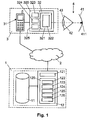
- reference numeral 1 denotes a computerized center comprising a video database 11 having stored video files and a computer having a plurality of functional modules.
- the database 11 is executed, for example, on the computer 12 or on a separate computer.
- the functional modules include a data compression module 120, a correlation value determination module 122, a bitmatrix generation module 123, a resolution reduction module 124, a pixel value reduction module 125, and a renewal frequency reduction module 126.
- the computer 12 also includes a communication module 121 for communicating over the cellular network 2 with the communication module 31 of the mobile terminal 3.
- the functional modules of the computer 12 are preferably implemented as programmed software modules for controlling one or more processors of the computer 12 and stored on a computer readable medium which is fixedly or removably connected to the computer 12.
- a computer readable medium which is fixedly or removably connected to the computer 12.
- the functional modules of computer 12 may be partially or completely implemented by hardware elements.
- the mobile radio network 2 is, for example, a GSM network (Global System for Mobile Communication), a UMTS network (Universal Mobile Telecommunications System), a WLAN network (Wireless Local Area Network), a UMA network (Unlicensed Mobile Access) or another satellite-based mobile radio system, for example.
- GSM Global System for Mobile Communication
- UMTS Universal Mobile Telecommunications System
- WLAN Wireless Local Area Network
- UMA Universal Mobile Access
- UMA Universal Mobile Access
- the mobile terminal 3 comprises a display unit 32 which is connected to the communication module 31 and which is embodied, for example, in the form of a pair of eye glasses that can be worn by the user or in another form that can be worn on the head.
- the communication module 31 and the display unit 32 are arranged, for example, in a common housing, or are arranged in separate housings and connected to each other via a wireless or contact-based communication link. If the communication module 31 is designed with its own separate housing, the communication module 31 is designed, for example, as a mobile telephone, as a PDA (personal data assistant), as a game station or as a laptop computer.
- PDA personal data assistant
- the mobile terminal 3 comprises a function block 320, which is embodied in the display unit 32 or in the communication module 31.
- the functional block 320 includes a plurality of functional modules, namely, a gaze feedback module 323, a data decompression module 324, and a data buffer module 325.
- the functional modules of the functional block 320 are implemented as programmed software modules, as hardware modules, or as combination modules (hardware and software).
- the display unit 32 comprises a display device 321 and a sight line determination module 322.
- the display device 321 is embodied, for example, as a virtual retinal display device which projects image signals directly onto the retina 41 of the user's eye 4.
- the sight line determination module 322 includes one called "Eye Tracker" which determines the position of the pupil 42 as an indicator of the viewing direction of the user.
- a virtual retinal display device with an eye tracker for example, in the patent application WO 94/09472 described.
- the display device 321 may also be implemented as an LCD (Liquid Crystal Display) display device, wherein the sight line determination module 322 determines the viewing direction based on a light reference mark projected onto the cornea 43 and the relative positioning of the pupil 42 relative thereto.
- Video data is obtained from the database 11 in the center 1, compressed by the data compression module 120 and transmitted to the communication module 31 of the mobile terminal 3 via the communication module 121 of the center 1 via the mobile radio network 2.
- the received compressed video data is decompressed by the data decompression module 324 and rendered visible to the user by the display device 321 as image signals.
- the data compression in the center 1 is based on information about the viewing direction of the user.
- the viewing direction of the user is determined by the viewing direction determination module 322 and transmitted by the viewing direction feedback module 323 by means of the communication module 31 via the mobile radio network 2 to the center 1.
- the current view direction position in the image defined by the video data is determined based on the received current viewing direction of the user.
- FIG. 6 shows an image section S in which the determined line of sight position is denoted by D.
- the viewing direction position D refers to a position between individual picture elements or exactly one picture element.
- reference numerals x and y refer to the coordinate axes for determining the positions of pixels in a two-dimensional image defined by the video data.
- the reference numeral t refers to an inverse time axis on which objects are represented based on their seniority. This means that objects with a high value on the time axis t have a high priority (eg t 1 ) and must be classified earlier than objects with a lower value on the time axis t which have a lower priority (eg t 2 or t 3 ) and must be classified later.
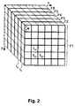
- FIG. 2 a plurality of temporally successive images F1, F2, F3, F4, F5 and F6 are shown, which are defined by the video data.
- the images F1, F2, F3, F4, F5, F6 are shown simplified with thirty-six pixels each.
- FIG. 2 only the picture elements f 24 , f 25 and f 26 are explicitly provided with reference symbols, the first index being the x-coordinate and the second index the y-coordinate (the position) of the relevant picture element in the picture F1, F2, F3, F4, F5, F6 indicates.
- the correlation value determination module 122 determines different (position-dependent) correlation threshold values for the picture elements depending on the current sighting position D. In essence, small correlation thresholds (ie, small tolerance) are provided for picture elements positioned near the current line of sight position D, whereas larger correlation thresholds (ie, larger tolerance) are provided for picture elements positioned further away from the current line of sight position D. For example, the correlation value determination module 122 determines different compression ranges A1, A2, A3, A4 depending on the distance to the current sighting position D, which have a greater correlation threshold value with greater distance to the viewing direction position D. The correlation thresholds are given as absolute or proportional numerical values.
- pixels in the compression area A1 are assigned a correlation threshold with the value zero (zero tolerance), for the compression area A2 a correlation threshold value 10% is provided, for the compression area A2 20% and for the compression area A3 40%.
- the difference of the pixel values of pixels in the compression area A3 should be up to 40% to be defined as correlating pixels.
- bitmap generation module 123 Based on the determined current correlation thresholds, the bitmap generation module 123 generates bit matrices which identify correlating picture elements with correlating pixel values. Generation by bitmatrix generation module 123 of bitmatrices identifying correlating image-contiguous pixels is described below with reference to FIG. Generation by bitmatrix rendering module 123 of bit matrices identifying correlating pixels in temporally successive images will be described below with reference to FIGS. 4 and 5.
- FIG. 3 shows a plurality of time-sequential bit matrices B1, B2, B3, B4, B5 and B6.
- the bit matrices B1, B2, B3, B4, B5, B6 are shown simplified with thirty-six bits each.
- FIG. 3 only the bit b 25 is explicitly provided with reference numbers, the indices indicating the x / y coordinates (position) of the bit in the bit matrix B1, B2, B3, B4, B5, B6 and the picture element in the picture F1 , F2, F3, F4, F5, F6 to which the bit refers.
- the bit matrix B1 with the time rank t 1 is assigned, for example, to the image F1 with the time rank t 1 and identifies picture elements in the picture F1 whose picture element values correlate with one another.
- the current position-dependent positions determined Correlation thresholds are used for the determination of the correlation of adjacent picture elements.
- the correlation in the horizontal direction is determined.
- the picture elements are identified, which lie in the image F1, F2, F3, F4, F5, F6 on a straight line parallel to the x-axis, adjoin one another and have correlating picture element values.
- the correlation in the vertical direction is determined.
- the picture elements are identified, which lie in the image F1, F2, F3, F4, F5, F6 on a straight line parallel to the y-axis, contiguous and have correlating pixel values.
- the resulting bit matrices for horizontal and vertical correlation are combined by a logical OR operation so that bit matrices B1, B2, B3, B4, B5 and B6 result.
- bit matrices B1, B2, B3, B4, B5 and B6 result.
- the pixel value in the compressed video data is encoded only once in a common data element, for example as the (arithmetic) average of the correlating data element values.
- a displaying bit (eg a bit set as "1") in the bit matrices B1, B2, B3, B4, B5 and B6 identifies the position in the associated image F1, F2, F3, F4, F5, F6 where the change from one first common pixel value of correlating pixels to the next common pixel value of correlating pixels.
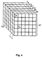
- FIG. 4 shows a plurality of time-sequential bit matrices B7, B8, B9, B10, B11 and B12.
- the bit matrices B7, B8, B9, B10, B11, B12 are shown in simplified form, each with thirty-six bits.
- the bit b 24 is explicitly provided with reference numerals, the indices indicating the x / y coordinates (position) of the bit in the bit matrix B7, B8, B9, B10, B11, B12 and the picture element in the picture F1 , F2, F3, F4, F5, F6 to which the bit refers.
- the bit matrix B7 with the time rank t 2 is For example, the image F2 associated with the time rank t 2 and identifies pixels in the image F2 whose pixel values each correlated with a pixel value of a similarly positioned pixel in the temporally preceding image F1 with the time rank t 1 (depending on the determined current position-dependent correlation thresholds). If a bit in the bit matrix is B7, B8, B9, B10, B11, B12 indicating (eg, set to the value "1”), it means that the pixel value of that pixel in the new image is equal to the pixel value of the similarly positioned pixel in the preceding picture and thus the picture element value is not included in the compressed video data for the new picture.
- the bit b 24 in the bit matrix B7 picture element f 24 in the frame F2 For example identifies the bit b 24 in the bit matrix B7 picture element f 24 in the frame F2, the pixel value with the pixel value of the pixel f 24 correlated in the image F1 (depending on the current correlation threshold for the picture element f 24). Accordingly, if the bit b is set in the bit matrix B7 24, the Schmefementwert of the pixel is f 24 is not included in the image F2 in the video data, as it is already 24 determines in the image F1 by the pixel value of the pixel f.
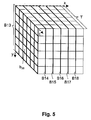
- FIG. 5 illustrates a plurality of bit matrices B13, B14, B15, B16, B17 and B18, each of which is based on a defined group of picture elements in a plurality of temporally successive pictures F1, F2, F3, F4, F5, F6 within a defined time interval T Respectively.
- the bit matrices B13, B14, B15, B16, B17, B18 refer to picture elements lying in planes parallel to the plane of the t / y coordinate system, wherein for each value of the picture in the x direction a bit matrice is provided, the picture elements identified with correlated pixel values.
- bit matrices B13, B14, B15, B16, B17, B18 are shown simplified with thirty-six bits each.
- the first index having the t coordinate (time rank) and the second index the y coordinate (position) of the relevant picture element in the pictures F1, F2, F3, F4, F5, F6 indicates.
- bitmatrix B13 identifies those correlating ones Image elements having an x coordinate value of zero are within the time interval T and adjoin each other in the t / y plane.
- the bit matrices B13, B14, B15, B16, B17 and B18 are generated as in determining correlating picture elements which are contiguous within an image.
- the pixel value in the compressed video data is again coded only once in a common data element, for example as the (arithmetic) average of the correlating data element values.
- a displaying bit eg, bit set as "1" in the bit matrices B13, B14, B15, B16, B17, and B18 identifies the position in the associated picture elements of the temporally successive pictures F1, F2, F3, F4, F5, F6. where the change from a first common pixel value of correlating pixels to the next common pixel value of correlating pixels occurs.
- bit matrices based on view direction dependent correlation thresholds is applicable to pixel values in both a gray value and a color value form, with each color value being treated as a separate pixel value for RGB (red, green, blue) video data becomes.
- pixels are coded depending on the current view direction position D with different (position-dependent) resolution.
- large resolutions i.e., small picture element sizes
- smaller resolutions i.e., larger picture element sizes
- a plurality of adjoining small picture elements are represented as a common picture elements in a common data element from a defined distance to the viewing direction position D.
- the pixel-value reduction module 125 determines a different (position-dependent) number of bits for encoding the pixel values, depending on the current line-of-sight position D. In essence, a larger number of bits are provided for pixel values of pixels positioned near the current line of sight position D than for pixel values of pixels positioned further away from the current line of sight position D.
- the renewal frequency reduction module 126 determines a different (position-dependent) communication frequency for the transmission of picture elements, depending on the current viewing direction position D. Essentially, a larger refresh rate is provided for pixel values of pixels near the current viewing direction position D are positioned, as for picture element values of picture elements that are positioned farther away from the current viewing direction position D.
- the refresh rate for the transmission of picture elements, the number of bits for the coding of the picture element values and / or the resolution of the picture elements are chosen, for example, as a function of the compression ranges A1, A2, A3, A4 mentioned above with reference to FIG. It should be clearly stated at this point that the quantities of the compression ranges A1, A2, A3, A4 shown in FIG. 6 are only to be understood as illustrative examples and not as limiting. Different sizes of the merging areas A1, A2, A3, A4 can be defined for the determination of the correlation threshold values, the number of bits for coding the pixel values, the resolution of the picture elements and / or the refreshing frequency.
- the compressed video data with the bit matrices and the data elements containing common pixel values of correlating picture elements are received in the mobile terminal 3 and buffered in the data buffer module 325.
- the received compressed video data is decompressed by the data decompression module 324 based on the associated bit matrices to a sequence of viewable images that are rendered by the display device 322 to the user as image signals.
- Image elements of different size (resolution) are mapped, for example, on the basis of size information on the displayable image.
- the data buffer module 325 At least the video data necessary for determining the current displayable picture are buffered in the data buffer module 325.
- Correlating picture elements in subsequent picture elements are determined on the basis of the assigned picture matrices and the relevant picture element values are obtained from the buffered video data.
- For bit matrices concerning picture elements in a plurality of temporally successive pictures at least the received video data for the time interval T are buffered in the data buffer module 325.
Landscapes
- Engineering & Computer Science (AREA)
- Multimedia (AREA)
- Signal Processing (AREA)
- Physics & Mathematics (AREA)
- General Health & Medical Sciences (AREA)
- Social Psychology (AREA)
- Health & Medical Sciences (AREA)
- General Physics & Mathematics (AREA)
- Databases & Information Systems (AREA)
- Computer Networks & Wireless Communication (AREA)
- Optics & Photonics (AREA)
- General Engineering & Computer Science (AREA)
- Computer Hardware Design (AREA)
- Theoretical Computer Science (AREA)
- Compression Or Coding Systems Of Tv Signals (AREA)
Abstract
Description
Die vorliegende Erfindung betrifft ein Verfahren und Vorrichtungen für die Übermittlung von Videodaten, die in einem Bild positionierbare Bildelemente mit Bildelementwerten umfassen, von einer Zentrale über ein Mabilfunknetz an ein mobiles Endgerät. Die vorliegende Erfindung betrifft insbesondere ein Verfahren für die Übermittlung von Videodaten, in welchem die Blickrichtung eines Benutzers mittels eines Blickrichtungsbestimmungsmoduls einer Anzeigeeinheit des mobilen Endgeräts bestimmt wird und in welchem die Blickrichtung vom Endgerät über das Mobilfunknetz an die Zentrale übermittelt wird. Die vorliegende Erfindung betrifft insbesondere auch eine computerbasierte Zentrale, ein mobiles Endgerät und ein Computerprogrammprodukt, welche für die Ausführung des Verfahrens geeignet sind.The present invention relates to a method and apparatus for the transmission of video data comprising pixel-positionable picture element picture elements from a central office via a mobile radio network to a mobile terminal. The present invention relates in particular to a method for the transmission of video data in which the viewing direction of a user is determined by means of a viewing direction determination module of a display unit of the mobile terminal and in which the viewing direction is transmitted from the terminal to the central office via the mobile radio network. In particular, the present invention also relates to a computer-based center, a mobile terminal and a computer program product which are suitable for carrying out the method.
In der Patentschrift
Es ist eine Aufgabe der vorliegenden Erfindung ein Verfahren und Vorrichtungen für die Übermittlung von Videodaten von einer Zentrale über ein Mobilfunknetz an ein mobiles Endgerät vorzuschlagen, welche eine Reduktion der zu übermittelnden Datenmenge ermöglichen.It is an object of the present invention to propose a method and apparatus for the transmission of video data from a center via a mobile network to a mobile terminal, which allow a reduction of the amount of data to be transmitted.
Gemäss der vorliegenden Erfindung werden diese Ziele insbesondere durch die Elemente der unabhängigen Ansprüche erreicht. Weitere vorteilhafte Ausführungsformen gehen ausserdem aus den abhängigen Ansprüchen und der Beschreibung hervor.According to the present invention, these objects are achieved in particular by the elements of the independent claims. Further advantageous embodiments are also evident from the dependent claims and the description.
Die oben genannten Ziele werden durch die vorliegende Erfindung insbesondere dadurch erreicht, dass zur Übermittlung von Videodaten, welche in einem Bild positionierbare Bildelemente mit Bildelementwerten umfassen, von einer Zentrale über ein Mobilfunknetz an ein mobiles Endgerät mit einer Anzeigeeinheit, eine Blickrichtung eines Benutzers der Anzeigeeinheit mittels eines Blickrichtungsbestimmungsmaduls der Anzeigeeinheit bestimmt wird, dass die Blickrichtung vom Endgerät über das Mobilfunknetz an die Zentrale übermittelt wird, dass in der Zentrale hinsichtlich des Bilds positionsabhängige Korrelationsschwellwerte basierend auf der Blickrichtung bestimmt werden, dass in der Zentrale Bitmatrizen erzeugt werden, die korrelierende Bildelemente mit korrelierenden Bildelementwerten identifizieren, wobei die korrelierenden Bildelemente abhängig von den Korrelationsschwellwerten bestimmt werden, dass die Bitmatrizen zusammen mit den Videodaten übermittelt werden, wobei für korrelierende Bildelemente jeweils ein gemeinsames Datenelement mit einem gemeinsamen Bildelementwert übermittelt wird, und dass Bildsignale durch die Anzeigeeinheit basierend auf den Videodaten und den Bitmatrizen wiedergegeben werden. Die Übermittlung der Videodaten findet insbesondere als sogenanntes "Videostreaming" kontinuierlich fliessend statt. Die Korrelationsschwellwerte für Positionen im Bild werden durch die Zentrale insbesondere jeweils abhängig von einer Distanz einer betreffenden Position im Bild zu einer der Blickrichtung entsprechenden Betrachtungsposition im Bild bestimmt. Die Anzeigeeinheit projiziert die Bildsignale beispielsweise direkt auf mindestens eine Retina des Benutzers. Die Bildwerte umfassen Grauwerte und/oder Farbwerte. Der Vorteil Korrelationsschwellwerte abhängig von der Blickrichtung des Benutzers zu bestimmen besteht darin, dass an Bildelemente, die in der Blickrichtung des Benutzers liegen, höhere Bedingungen an die Korrelation der Bildelementwerte gestellt werden können, als an Bildelemente, die ausserhalb der Blickrichtung liegen. Dadurch ist es möglich, Bildelementwerte von Bildelementen, die ausserhalb der Blickrichtung des Benutzers liegen, auch bei grösseren Unterschieden in den Bildelementwerten in einem gemeinsamen Datenelement zusammenzufassen und damit die Datenmenge der zu übermittelnden Videodaten zu komprimieren, ohne beim Benutzer die subjektive Wahrnehmung der wiedergegebenen Videodaten qualitativ wesentlich zu beeinträchtigen. Insbesondere bei Virtuellen Retinalen Anzeigeeinheiten, welche Bildsignale direkt auf die Retina projizieren, kann die Datenmenge signifikant reduziert werden, da ausserhalb der Blickrichtung liegende Bildelemente in ausserhalb der Fovea liegende Retinabereiche projiziert werden, welche eine geringere Empfindlichkeit aufweisen als die Fovea.The above-mentioned objects are achieved by the present invention, in particular, that for transmitting video data, which comprise image elements with pixel values positionable in an image, from a control center via a mobile radio network to a mobile terminal with a display unit, a viewing direction of a user of the display unit a Blickrichtungsbestimmungsmaduls the display unit is determined that the viewing direction is transmitted from the terminal via the mobile network to the center, that are determined in the center with respect to the image position-dependent correlation thresholds based on the line of sight that bitmatrices are generated in the center, the correlating pixels with correlating Identifying pixel values, wherein the correlating pixels are determined depending on the correlation thresholds that the bit matrices are transmitted together with the video data, wherein for correlating pixels each a common data element with a common pixel value is transmitted, and that image signals by the display unit based on the video data and be played back the bit matrices. The transmission of the video data takes place in particular as so-called "video streaming" continuously flowing. The correlation threshold values for positions in the image are determined by the central office in each case depending on a distance of a respective position in the image to a viewing position corresponding to the viewing direction in the image. The display unit projects the image signals, for example, directly to at least one retina of the user. The image values include gray values and / or color values. The advantage of determining correlation threshold values as a function of the viewing direction of the user is that higher conditions can be placed on the correlation of the pixel values on pixels which lie in the viewing direction of the user than on pixels which lie outside the line of sight. As a result, it is possible to combine picture element values of picture elements which lie outside the line of sight of the user in a common data element even with larger differences in the picture element values and thus to compress the data volume of the video data to be transmitted, without the user qualitatively having the subjective perception of the reproduced video data significantly affect. Especially in the case of virtual retinal display units, which project image signals directly onto the retina, the amount of data can can be significantly reduced, since out-of-sight pixels are projected into retinal areas outside the fovea, which have lower sensitivity than the fovea.
Vorzugsweise umfasst die Erzeugung der Bitmatrizen in der Zentrale eine Identifizierung von im Bild aneinandergrenzenden Bildelementen, die korrelierende Bildelementwerte aufweisen. Wie in der Patentanmeldung
Vorzugsweise umfasst die Erzeugung der Bitmatrizen in der Zentrale eine Identifizierung von in zeitlich aufeinanderfolgenden Bildern gleich positionierten Bildelementen, die korrelierende Bildelementwerte aufweisen. Da die Wiedergabe von bewegten Bildern im wesentlichen der Wiedergabe einer Sequenz von Bildern (so genannte Vollbilder oder "frames", die hier als Bild bezeichnet werden) entspricht, kann die zur Übermittlung von Videodaten erforderliche Datenmenge reduziert werden, wenn Bildelemente mit korrelierenden Bildelementwerten, die in aufeinanderfolgenden Bildern gleich positioniert sind, in einer Bitmatrize angezeigt werden und deren Bildelementwert nur einmal übermittelt wird. Die Bitmatrizen zeigen die Korrelation der Bildelemente von zwei aufeinanderfolgenden Bildern oder von mehreren aufeinanderfolgenden Bildern an.Preferably, the generation of the bit matrices in the center comprises an identification of picture elements which are equally positioned in temporally successive images and have correlating pixel values. Since the reproduction of moving pictures essentially corresponds to the reproduction of a sequence of pictures (so-called frames), the amount of data required to transmit video data can be reduced if picture elements having correlated picture element values, are positioned identically in successive images, displayed in a bitmatrix, and their pixel value is communicated only once. The bit matrices indicate the correlation of the picture elements of two consecutive pictures or of several consecutive pictures.
In einer Ausführungsvariante werden Bildelementwerte von Bildelementen, die im Bild eine definierte Distanz zu einer der Blickrichtung entsprechenden Betrachtungsposition im Bild aufweisen, von der Zentrale mit einer geringeren Anzahl Bits repräsentiert als Bildelementwerte von Bildelementen bei der Betrachtungsposition. Durch die Reduktion der Bitanzahl für die Codierung von Bildelementwerten für Bildelemente, die ausserhalb der Blickrichtung des Benutzers liegen, kann die Datenmenge der zu übermittelnden Videodaten komprimiert werden, ohne beim Benutzer die subjektive Wahmehmung der wiedergegebenen Videodaten qualitativ wesentlich zu beeinträchtigen.In one embodiment, pixel values of picture elements that correspond in the image to a defined distance to one of the viewing direction become Viewing position in the image, represented by the central office with a fewer number of bits than pixel values of pixels in the viewing position. By reducing the number of bits for the encoding of pixel values for pixels that are outside the line of sight of the user, the amount of data to be transmitted video data can be compressed without affecting the quality of the subjective perception of the reproduced video data in the user.
In einer Ausführungsvariante werden mehrere aneinandergrenzende Bildelemente, die im Bild eine definierte Distanz zu einer der Blickrichtung entsprechenden Betrachtungsposition im Bild aufweisen, von der Zentrale als gemeinsames Bildelement in einem gemeinsamen Datenelement repräsentiert. Durch die Zusammenfassung von aneinandergrenzenden Bildelementen, die ausserhalb der Blickrichtung des Benutzers liegen, wird die geometrische Ausdehnung (Grösse) der Bildelemente erhöht, das heisst die örtliche Auflösung von Bildbereichen ausserhalb der Blickrichtung reduziert, so dass die Datenmenge der zu übermittelnden Videodaten komprimiert wird, ohne beim Benutzer die subjektive Wahmehmung der wiedergegebenen Videodaten qualitativ wesentlich zu beeinträchtigen.In one embodiment, a plurality of adjoining picture elements, which in the picture have a defined distance to a viewing position corresponding to the viewing direction in the picture, are represented by the central office as a common picture element in a common data element. By combining contiguous picture elements which are outside the viewing direction of the user, the geometric extension (size) of the picture elements is increased, that is to say the spatial resolution of picture areas outside the viewing direction is reduced, so that the data volume of the video data to be transmitted is compressed without to significantly affect the user's subjective perception of the reproduced video data.
In einer Ausführungsvariante werden Bildelemente, die im Bild eine definierte Distanz zu einer der Blickrichtung entsprechenden Betrachtungsposition im Bild aufweisen, von der Zentrale mit einer reduzierten Emeuerungsfrequenz an das mobile Endgerät übermittelt. Durch die Reduktion der Emeuerungsfrequenz von Bildelementen, die ausserhalb der Blickrichtung des Benutzers liegen, wird die Datenmenge der zu übermittelnden Videodaten komprimiert, ohne beim Benutzer die subjektive Wahmehmung der wiedergegebenen Videodaten qualitativ wesentlich zu beeinträchtigen.In one embodiment, picture elements which have a defined distance in the picture to a viewing position corresponding to the viewing direction in the picture are transmitted from the center to the mobile terminal at a reduced refresh rate. By reducing the Emeuerungsfrequenz of pixels that are outside the line of sight of the user, the amount of data to be transmitted video data is compressed without affecting the user's subjective perception of the reproduced video data quality significantly.
Die vorliegende Erfindung bezieht sich zudem auf ein Computerprogrammprodukt mit Computerprogrammcodemitteln zur Steuerung eines oder mehrerer Prozessoren eines Computers, derart, dass der Computer eine Zentrale zur Ausführung des Verfahrens für die Übermittlung der Videodaten repräsentiert. Das Computerprogrammprodukt umfasst insbesondere ein computerlesbares Medium, das die Computerprogrammcodemittel enthält.The present invention also relates to a computer program product with computer program code means for control one or more processors of a computer, such that the computer represents a central office for carrying out the method for the transmission of the video data. In particular, the computer program product comprises a computer-readable medium containing the computer program code means.
Nachfolgend wird eine Ausführung der vorliegenden Erfindung anhand eines Beispieles beschrieben. Das Beispiel der Ausführung wird durch die folgenden beigelegten Figuren illustriert:
Figur 1 zeigt ein Blockdiagramm eines Videodatenübermittlungssystems, welches eine computerbasierte Zentrale umfasst, die über ein Mobilfunknetz mit einem mobilen Endgerät verbindbar ist, das eine Anzeigeeinheit aufweist.Figur 2 zeigt eine schematische Darstellung eines Beispiels von mehreren zeitlich aufeinanderfolgenden Bildern, welche jeweils mehrere im Bild positionierbare Bildelemente umfassen.Figur 3 zeigt eine schematische Darstellung eines Beispiels von mehreren Bitmatrizen, die für Bilder derFigur 2 aneinandergrenzende Bildelemente mit korrelierenden Bildelemeniwerten identifizieren.- Figur 4 zeigt eine schematische Darstellung eines Beispiels von mehreren Bitmatrizen, die jeweils für zwei zeitlich aufeinanderfolgende Bilder der
Figur 2 gleich positionierte Bildelemente mit korrelierenden Bildelementwerten identifizieren. - Figur 5 zeigt eine schematische Darstellung eines Beispiels von mehreren Bitmatrizen, die jeweils für mehrere zeitlich aufeinanderfolgende Bilder der
Figur 2 Bildelemente mit korrelierenden Bildelementwarten identifizieren. - Figur 6 zeigt ein Beispiel eines Ausschnitts aus einem Bild, in welchem verschiedene Komprimierungsbereiche mit unterschiedlicher Distanz zu einer Betrachtungsposition dargestellt werden.
- Figure 1 shows a block diagram of a video data transmission system comprising a computer-based center, which is connectable via a mobile network to a mobile terminal having a display unit.
- FIG. 2 shows a schematic illustration of an example of a plurality of temporally successive images which each comprise a plurality of image elements which can be positioned in the image.
- FIG. 3 shows a schematic representation of an example of a plurality of bit matrices which identify adjacent image elements with correlating image element values for images of FIG.
- FIG. 4 shows a schematic representation of an example of a plurality of bit matrices which identify image elements with correlated pixel values which are positioned identically for two temporally successive images of FIG.
- FIG. 5 shows a schematic representation of an example of a plurality of bit matrices, each for a plurality of temporally successive ones Images of Figure 2 Identify picture elements with correlating picture element panels.
- FIG. 6 shows an example of a section of an image in which different compression areas are shown at different distances from a viewing position.
In der Figur 1 bezeichnet das Bezugszeichen 1 eine computerisierte Zentrale, welche eine Videodatenbank 11 mit gespeicherten Videodateien sowie einen Computer mit mehreren Funktionsmodulen umfasst. Die Datenbank 11 ist beispielsweise auf dem Computer 12 oder auf einem separaten Computer ausgeführt. Die Funktionsmodule umfassen ein Datenkomprimierurigsmodul 120, ein Korrelationswertbestimmungsmodul 122, ein Bitmatrizenerzeugungsmodul 123, ein Auflösungsreduktionsmodul 124, ein Bildelementwertreduktionsmodul 125 sowie ein Emeuerungsfrequenzreduktionsmodul 126. Der Computer 12 umfasst insbesondere auch ein Kommunikationsmodul 121 für den Datenaustausch über das Mobilfunknetz 2 mit dem Kommunikationsmodul 31 des mobilen Endgeräts 3. Die Funktionsmodule des Computers 12 sind vorzugsweise als programmierte Softwaremodule zur Steuerung eines oder mehrerer Prozessoren des Computers 12 ausgeführt und auf einem computerlesbaren Medium gespeichert, das fest oder entfembar mit dem Computer 12 verbunden ist. Der Fachmann wird verstehen, dass die Funktionsmodule des Computers 12 teilweise oder vollständig mittels Hardwareelementen ausgeführt werden können.In Fig. 1,
Das Mobilfunknetz 2 ist beispielsweise ein GSM-Netz (Global System for Mobile Communication), ein UMTS-Netz (Universal Mobile Telecommunications System), ein WLAN-Netz (Wireless Local Area Network), ein UMA-Netz (Unlicensed Mobile Access) oder ein anderes beispielsweise satellitenbasiertes Mobilfunksystem. Der Fachmann wird verstehen, dass das vorgeschlagene Verfahren auch über andere Telekommunikationsnetze, insbesondere über Festnetze anwendbar ist.The
Das mobile Endgerät 3 umfasst eine mit dem Kommunikationsmodul 31 verbundene Anzeigeeinheit 32, welche beispielsweise in der Form einer durch den Benutzer tragbaren Sehbrille oder in einer anderen auf dem Kopf tragbaren Form ausgeführt ist. Das Kommunikationsmodul 31 und die Anzeigeeinheit 32 sind beispielsweise in einem gemeinsamen Gehäuse angeordnet, oder sind in separaten Gehäusen angeordnet und über eine drahtlose oder kontaktbasierte Kommunikationsverbindung miteinander verbunden. Wenn das Kommunikationsmodul 31 mit einem eigenen separaten Gehäuse ausgeführt ist, ist das Kommunikationsmodul 31 beispielsweise als Mobilfunktelefon, als PDA (Personal Data Assistant), als Spielstation oder als Laptop-Computer ausgeführt.The
Wie in der Figur 1 schematisch dargestellt ist, umfasst das mobile Endgerät 3 einen Funktionsblock 320, der in der Anzeigeeinheit 32 oder im Kommunikationsmodul 31 ausgeführt ist. Der Funktionsblock 320 umfasst mehrere funktionale Module, nämlich ein Blickrichtuhgsrückmeldemodul 323, ein Datendekompressionsmodul 324 sowie ein Datenpuffermodul 325. Die funktionalen Module des Funktionsblocks 320 sind als programmierte Softwaremodule, als Hardwaremodule oder als Kombinationsmodule (Hardware und Software) ausgeführt.As shown schematically in FIG. 1, the
Die Anzeigeeinheit 32 umfasst eine Anzeigevorrichtung 321 sowie ein Blickrichtungsbestimmungsmodul 322. Die Anzeigevorrichtung 321 ist beispielsweise als Virtuelle Retinale Anzeigevorrichtung ausgeführt, welche Bildsignale direkt auf die Retina 41 des Auges 4 des Benutzers projiziert. Das Blickrichtungsbestimmungsmodul 322 umfasst beispielsweise einen so genannten "Eye Tracker" der die Position der Pupille 42 als Indikator für die Blickrichtung des Benutzers ermittelt. Eine Virtuelle Retinale Anzeigevorrichtung mit einem Eye Tracker wird beispielsweise in der Patentanmeldung
Videodaten werden in der Zentrale 1 aus der Datenbank 11 bezogen, durch das Datenkompressionsmodul 120 komprimiert und mittels des Kommunikationsmoduls 121 der Zentrale 1 über das Mobilfunknetz 2 an das Kommunikationsmodul 31 des mobilen Endgeräts 3 übermittelt. Die empfangenen komprimierten Videodaten werden durch das Datendekompressionsmodul 324 dekomprimiert und durch die Anzeigevorrichtung 321 für den Benutzer sichtbar als Bildsignale wiedergegeben. Wie im folgenden beschrieben wird, erfolgt die Datenkompression in der Zentrale 1 auf Grund von Angaben über die Blickrichtung des Benutzers. Die Blickrichtung des Benutzers wird durch das Blickrichtungsbestimmungsmodul 322 bestimmt und durch das Blickrichtungsrückmeldemodul 323 mittels des Kommunikationsmoduls 31 über das Mobilfunknetz 2 an die Zentrale 1 übermittelt.Video data is obtained from the
Im Datenkomprimierungsmodul 120 wird auf Grund der empfangenen aktuellen Blickrichtung des Benutzers die aktuelle Blickrichtungsposition im durch die Videodaten definierten Bild bestimmt. In der Figur 6 wird ein Bildausschnitt S gezeigt, in welchem die ermittelte Blickrichtungsposition mit D bezeichnet ist. Die Blickrichtungsposition D bezieht sich auf eine Position zwischen einzelnen Bildelementen oder genau auf einem Bildelement.In the
In den Figuren 2, 3, 4, 5 und 6 beziehen sich die Bezugszeichen x und y auf die Koordinatenachsen zur Bestimmung der Positionen von Bildelementen in einem zweidimensionalen Bild, das durch die Videodaten definiert ist. In den Figuren 2, 3, 4 und 5 bezieht sich das Bezugszeichen t auf eine inverse Zeitachse, auf der Objekte auf Grund ihres Zeitrangs dargestellt werden. Das heisst Objekte mit einem hohen Wert auf der Zeitachse t haben einen hohen Zeitrang (z.B. t1) und müssen zeitlich früher eingestuft werden als Objekte mit einem tieferen Wert auf der Zeitachse t welche einen tieferen Zeitrang (z.B. t2 oder t3) aufweisen und zeitlich später eingestuft werden müssen.In Figs. 2, 3, 4, 5 and 6, reference numerals x and y refer to the coordinate axes for determining the positions of pixels in a two-dimensional image defined by the video data. In Figures 2, 3, 4 and 5, the reference numeral t refers to an inverse time axis on which objects are represented based on their seniority. This means that objects with a high value on the time axis t have a high priority (eg t 1 ) and must be classified earlier than objects with a lower value on the time axis t which have a lower priority (eg t 2 or t 3 ) and must be classified later.
In der Figur 2 werden mehrere zeitlich aufeinanderfolgende Bilder F1, F2, F3, F4, F5 und F6 dargestellt, die durch die Videodaten definiert sind. Die Bilder F1, F2, F3, F4, F5, F6 sind vereinfacht mit jeweils sechsunddreissig Bildelementen dargestellt. In der Figur 2 sind einzig die Bildelemente f24, f25 und f26 explizit mit Bezugszeichen versehen, wobei der erste Index die x-Koordinate und der zweite Index die y-Koordinate (der Position) des betreffenden Bildelements im Bild F1, F2, F3, F4, F5, F6 angibt.In Figure 2, a plurality of temporally successive images F1, F2, F3, F4, F5 and F6 are shown, which are defined by the video data. The images F1, F2, F3, F4, F5, F6 are shown simplified with thirty-six pixels each. In FIG. 2, only the picture elements f 24 , f 25 and f 26 are explicitly provided with reference symbols, the first index being the x-coordinate and the second index the y-coordinate (the position) of the relevant picture element in the picture F1, F2, F3, F4, F5, F6 indicates.
Das Korrelationswertbestimmungsmodul 122 bestimmt abhängig von der aktuellen Blickrichtungsposition D unterschiedliche (positionsabhängige) Korrelationsschwellwerte für die Bildelemente. Im wesentlichen werden kleine Korrelationsschwellwerte (d.h. kleine Toleranz) vorgesehen für Bildelemente, die in der Nähe der aktuellen Blickrichtungsposition D positioniert sind, wohingegen grössere Korrelationsschwellwerte (d.h. grössere Toleranz) vorgesehen werden für Bildelemente, die weiter entfernt von der aktuellen Blickrichtungsposition D positioniert sind. Beispielsweise bestimmt das Korrelationswertbestimmungsmodul 122 abhängig von der Distanz zur aktuellen Blickrichtungsposition D verschiedene Komprimierungsbereiche A1, A2, A3, A4, welche mit grösserer Distanz zur Blickrichtungsposition D einen grösseren Korrelationsschwellwert aufweisen. Die Korrelationsschwellwerte werden als absolute oder proportionale Zahlenwerte angegeben. Beispielsweise werden Bildelementen im Komprimierungsbereich A1 ein Korrelationsschwellwert mit dem Wert Null (Nulltoleranz) zugeordnet, für den Komprimierungsbereich A2 wird ein Korrelationsschwellwert 10% vorgesehen, für den Komprimierungsbereich A2 20% und für den Komprimierungsbereich A3 40%. In diesem Beispiel dürfte der Unterschied der Bildelementwerte von Bildelementen im Komprimierungsbereich A3 bis zu 40% betragen, um als korrelierende Bildelemente definiert zu werden.The correlation
Auf Grund der bestimmten aktuellen Korrelationsschwellwerte erzeugt das Bitmatrizenerzeugungsmodul 123 Bitmatrizen, welche korrelierende Bildelemente mit korrelierenden Bildelementwerten identifizieren. Die Erzeugung durch das Bitmatrizenerzeugungsmodul 123 von Bitmatrizen, die korrelierende, in einem Bild aneinandergrenzende Bildelemente identifizieren, wird nachfolgend mit Bezug zur Figur 3 beschrieben. Die Erzeugung durch das Bitmatrizenerceugungsmodul 123 von Bitmatrizen, die korrelierende Bildelemente in zeitlich aufeinanderfolgenden Bildern identifizieren, wird danach mit Bezug zu den Figuren 4 und 5 beschrieben.Based on the determined current correlation thresholds, the
In der Figur 3 werden mehrere zeitlich aufeinanderfolgende Bitmatrizen B1, B2, B3, B4, B5 und B6 dargestellt. Entsprechend den vereinfachten Bildern F1, F2, F3, F4, F5, F6 der Figur 2 sind die Bitmatrizen B1, B2, B3, B4, B5, B6 vereinfacht mit jeweils sechsunddreissig Bits dargestellt. In der Figur 3 ist einzig das Bit b25 explizit mit Bezugszeichen versehen, wobei die Indizes die x/y-Koordinaten (Position) des Bits in der Bitmatrix B1, B2, B3, B4, B5, B6 angeben und das Bildelement im Bild F1, F2, F3, F4, F5, F6 bestimmen, auf das sich das Bit bezieht. Die Bitmatrix B1 mit dem Zeitrang t1 ist beispielsweise dem Bild F1 mit dem Zeitrang t1 zugeordnet und identifiziert Bildelemente im Bild F1 deren Bildelementwert miteinander korrelieren. Die Bitmatrizen B1, B2, B3, B4, B5 und B6 werden beispielsweise nach dem in
In der Figur 4 werden mehrere zeitlich aufeinanderfolgende Bitmatrizen B7, B8, B9, B10, B11 und B12 dargestellt. Entsprechend den vereinfachten Bildern F1, F2, F3, F4, F5, F6 der Figur 2 sind die Bitmatrizen B7, B8, B9, B10, B11, B12 vereinfacht mit jeweils sechsunddreissig Bits dargestellt. In der Figur 4 ist einzig das Bit b24 explizit mit Bezugszeichen versehen, wobei die Indizes die x/y-Koordinaten (Position) des Bits in der Bitmatrix B7, B8, B9, B10, B11, B12 angeben und das Bildelement im Bild F1, F2, F3, F4, F5, F6 bestimmen, auf das sich das Bit bezieht. Die Bitmatrix B7 mit dem Zeitrang t2 ist beispielsweise dem Bild F2 mit dem Zeitrang t2 zugeordnet und identifiziert Bildelemente im Bild F2 deren Bildelementwerte jeweils mit einem Bildelementwert eines gleich positionierten Bildelements im zeitlich vorausgehenden Bild F1 mit dem Zeitrang t1 korreliert (abhängig von den bestimmten aktuellen positionsabhängigen Korrelationsschwellwerten). Wenn ein Bit in der Bitmatrix B7, B8, B9, B10, B11, B12 anzeigend (z.B. auf den Wert "1" gesetzt) ist, bedeutet dies, dass der Bildelementwert des betreffenden Bildelements im neuen Bild mit dem Bildelementwert des gleich positionierten Bildelements im vorausgehenden Bild korreliert und somit der Bildelementwert in den komprimierten Videodaten für das neue Bild nicht enthalten ist. Zum Beispiel identifiziert das Bit b24 in der Bitmatrix B7 das Bildelement f24 im Bild F2, dessen Bildelementwert mit dem Bildelementwert des Bildelements f24 im Bild F1 korreliert (abhängig vom aktuellen Korrelationsschwellwert für das Bildelement f24). Wenn folglich das Bit b24 in der Bitmatrix B7 gesetzt ist, so ist der Bildefementwert des Bildelements f24 im Bild F2 nicht in den Videodaten enthalten, da er bereits durch den Bildelementwert des Bildelements f24 im Bild F1 bestimmt ist.FIG. 4 shows a plurality of time-sequential bit matrices B7, B8, B9, B10, B11 and B12. According to the simplified pictures F1, F2, F3, F4, F5, F6 of FIG. 2, the bit matrices B7, B8, B9, B10, B11, B12 are shown in simplified form, each with thirty-six bits. In FIG. 4, only the bit b 24 is explicitly provided with reference numerals, the indices indicating the x / y coordinates (position) of the bit in the bit matrix B7, B8, B9, B10, B11, B12 and the picture element in the picture F1 , F2, F3, F4, F5, F6 to which the bit refers. The bit matrix B7 with the time rank t 2 is For example, the image F2 associated with the time rank t 2 and identifies pixels in the image F2 whose pixel values each correlated with a pixel value of a similarly positioned pixel in the temporally preceding image F1 with the time rank t 1 (depending on the determined current position-dependent correlation thresholds). If a bit in the bit matrix is B7, B8, B9, B10, B11, B12 indicating (eg, set to the value "1"), it means that the pixel value of that pixel in the new image is equal to the pixel value of the similarly positioned pixel in the preceding picture and thus the picture element value is not included in the compressed video data for the new picture. For example identifies the bit b 24 in the bit matrix B7 picture element f 24 in the frame F2, the pixel value with the pixel value of the pixel f 24 correlated in the image F1 (depending on the current correlation threshold for the picture element f 24). Accordingly, if the bit b is set in the bit matrix B7 24, the Bildefementwert of the pixel is f 24 is not included in the image F2 in the video data, as it is already 24 determines in the image F1 by the pixel value of the pixel f.
In der Figur 5 werden mehrere Bitmatrizen B13, B14, B15, B16, B17 und B18 dargestellt, die sich jeweils auf eine definierte Gruppe von Bildelementen in mehreren zeitlich aufeinanderfolgenden Bildern F1, F2, F3, F4, F5, F6 innerhalb eines definierten Zeitintervalls T beziehen. Die Bitmatrizen B13, B14, B15, B16, B17, B18 beziehen sich auf Bildelemente, die in Ebenen parallel zur Ebene des t/y-Koordinatensystems liegen, wobei für jeden Wert des Bilds in der x-Richtung eine Bitmatrize vorgesehen ist, die Bildelemente mit korrelierenden Bildelementwerten identifiziert. Die Bitmatrizen B13, B14, B15, B16, B17, B18 sind vereinfacht mit jeweils sechsunddreissig Bits dargestellt. In der Figur 5 ist einzig das Bit b35 explizit mit Bezugszeichen versehen, wobei der erste Index die t-Koordinate (Zeitrang) und der zweite Index die y-Koordinate (Position) des betreffenden Bildelements im Bild F1, F2, F3, F4, F5, F6 angibt. Die Bitmatrix B13 identifiziert beispielsweise diejenigen korrelierenden Bildelemente, die einen x-Koordinatenwert von Null aufweisen, innerhalb des Zeitintervalls T liegen und in der t/y-Ebene aneinandergrenzen. Die Bitmatrizen B13, B14, B15, B16, B17 und B18 werden wie bei der Bestimmung korrelierender Bildelemente, die innerhalb eines Bilds aneinandergrenzen, erzeugt. Es werden jedoch für die Bestimmung der korrelierenden Bildelemente Bildelemente untersucht, die in einer Ebene benachbart sind, die durch mehrere zeitlich aufeinanderfolgende Bilder verläuft. Mit anderen Worten, in der horizontalen Richtung wird die Korrelation von Bildelementen untersucht, die innerhalb des Zeitintervalls T auf einer Geraden parallel zur Zeitachse t liegen. In der vertikalen Richtung wird die Korrelation von Bildelementen untersucht, die innerhalb des Zeitintervalls T auf einer Geraden parallel zur y-Achse liegen. Anschliessend werden die resultierenden Bitmatrizen für die horizontale und vertikale Komelation durch eine logische ODER-Operation miteinander kombiniert, so dass die Bitmatrizen B13, B14, B15, B16, B17 und B18 resultieren. Für komelierende Bildelemente wird der Bildelementwert in den komprimierten Videodaten wiederum nur einmal in einem gemeinsamen Datenelement codiert, beispielsweise als (arithmetischer) Durchschnitt der korrelierenden Datenelementwerte. Ein anzeigendes Bit (z.B. ein als "1" gesetztes Bit) in den Bitmatrizen B13, B14, B15, B16, B17 und B18 identifiziert die Position in den zugeordneten Bildelementen der zeitlich aufeinanderfolgenden Bilder F1, F2, F3, F4, F5, F6, wo der Wechsel von einem ersten gemeinsamen Bildelementwert korrelierender Bildelemente auf den nächsten gemeinsamen Büdelementwert korrelierender Bildelemente stattfindet.FIG. 5 illustrates a plurality of bit matrices B13, B14, B15, B16, B17 and B18, each of which is based on a defined group of picture elements in a plurality of temporally successive pictures F1, F2, F3, F4, F5, F6 within a defined time interval T Respectively. The bit matrices B13, B14, B15, B16, B17, B18 refer to picture elements lying in planes parallel to the plane of the t / y coordinate system, wherein for each value of the picture in the x direction a bit matrice is provided, the picture elements identified with correlated pixel values. The bit matrices B13, B14, B15, B16, B17, B18 are shown simplified with thirty-six bits each. In FIG. 5, only the bit b 35 is explicitly provided with reference symbols, the first index having the t coordinate (time rank) and the second index the y coordinate (position) of the relevant picture element in the pictures F1, F2, F3, F4, F5, F6 indicates. For example, bitmatrix B13 identifies those correlating ones Image elements having an x coordinate value of zero are within the time interval T and adjoin each other in the t / y plane. The bit matrices B13, B14, B15, B16, B17 and B18 are generated as in determining correlating picture elements which are contiguous within an image. However, for determining the correlating picture elements, picture elements adjacent to a plane passing through a plurality of temporally successive pictures are examined. In other words, in the horizontal direction, the correlation of picture elements which lie within the time interval T on a straight line parallel to the time axis t is examined. In the vertical direction, the correlation of picture elements which lie within the time interval T on a straight line parallel to the y-axis is examined. Subsequently, the resulting bit matrices for the horizontal and vertical comelations are combined by a logical OR operation so that the bit matrices B13, B14, B15, B16, B17 and B18 result. For comelining pixels, the pixel value in the compressed video data is again coded only once in a common data element, for example as the (arithmetic) average of the correlating data element values. A displaying bit (eg, bit set as "1") in the bit matrices B13, B14, B15, B16, B17, and B18 identifies the position in the associated picture elements of the temporally successive pictures F1, F2, F3, F4, F5, F6. where the change from a first common pixel value of correlating pixels to the next common pixel value of correlating pixels occurs.
Der Fachmann wird verstehen, dass die Erzeugung von Bitmatrizen basierend auf blickrichtungsabhängigen Korrelationsschwellwerten auf Bildelementwerte sowohl in der Form eines Grauwerts als auch in der Form eines Farbwerts anwendbar ist, wobei bei RGB-Videodaten (Rot, Grün, Blau) jeder Farbwert als separater Bildelementwert behandelt wird.Those skilled in the art will understand that the generation of bit matrices based on view direction dependent correlation thresholds is applicable to pixel values in both a gray value and a color value form, with each color value being treated as a separate pixel value for RGB (red, green, blue) video data becomes.
Für die Bestimmung von korrelierenden Bildelementen in zeitlich aufeinanderfolgenden Bildern (nach Figur 4 oder 5) können andere Korrelationsschwellwerte bestimmt und angewandt werden als für die Bestimmung von korrelierenden Bildelementen, die in einem Bild aneinandergrenzen (nach Figur 3).For the determination of correlating picture elements in temporally successive pictures (according to FIG. 4 or 5), other correlation threshold values can be determined and used than for the determination of correlating picture elements that adjoin one another in an image (according to FIG. 3).
Durch das Auflösungsreduktionsmodul 124 werden Bildelemente abhängig von der aktuellen Blickrichtungsposition D mit unterschiedlicher (positionsabhängiger) Auflösung codiert. Im wesentlichen werden grosse Auflösungen (d.h. kleine Bildelementgrössen) vorgesehen für Bildelemente, die in der Nähe der aktuellen Blickrichtungsposition D positioniert sind, wohingegen kleinere Auflösungen (d.h. grössere Bildelementgrössen) vorgesehen werden für Bildelemente, die weiter entfernt von der aktuellen Blickrichtungsposition D positioniert sind. Mit anderen Worten, mehrere aneinandergrenzende kleine Bildelemente, werden ab einer definierten Distanz zu der Blickrichtungsposition D als gemeinsame Bildelemente in einem gemeinsamen Datenelement repräsentiert.By the
Das Bildelementwertreduktionsmodul 125 bestimmt abhängig von der aktuellen Blickrichtungsposition D eine unterschiedliche (positionsabhängige) Anzahl von Bits für die Codierung der Bildelementwerte. Im wesentlichen wird eine grössere Anzahl Bits vorgesehen für Bildelementwerte von Bildelementen, die in der Nähe der aktuellen Blickrichtungsposition D positioniert sind, als für Bildelementwerte von Bildelementen, die weiter entfernt von der aktuellen Blickrichtungsposition D positioniert sind.The pixel-
Das Erneuerungsfrequenzreduktionsmodul 126 bestimmt abhängig von der aktuellen Blickrichtungsposition D eine unterschiedliche (positionsabhängige) Emeuerungsfrequenz für die Übermittlung von Bildelementen. Im wesentlichen wird eine grössere Emeuerungsfrequenz vorgesehen für Bildelementwerte von Bildelementen, die in der Nähe der aktuellen Blickrichtungsposition D positioniert sind, als für Bildelementwerte von Bildelementen, die weiter entfernt von der aktuellen Blickrichtungsposition D positioniert sind.The renewal
Die Emeuerungsfrequenz für die Übermittlung von Bildelementen, die Anzahl Bits für die Codierung der Bildelementwerte und/oder die Auflösung der Bildelemente werden beispielsweise abhängig von den oben mit Bezug zu Figur 6 erwähnten Komprimierungsbereichen A1, A2, A3, A4 gewählt. An dieser Stelle soll klar festgehalten werden, dass die in der Figur 6 dargestellten Grössen der Komprimierungsbereiche A1, A2, A3, A4 nur als illustrierende Beispiele und nicht einschränkend zu verstehen sind. Verschiedene Grössen der Kompnmierungsbereiche A1, A2, A3, A4 können für die Bestimmung der Korrelationsschwellwerte, die Anzahl Bits für Codierung der Bildelementwerte, die Auflösung der Bildelemente und/oder der Emeuerungsfrequenz definiert werden.The refresh rate for the transmission of picture elements, the number of bits for the coding of the picture element values and / or the resolution of the picture elements are chosen, for example, as a function of the compression ranges A1, A2, A3, A4 mentioned above with reference to FIG. It should be clearly stated at this point that the quantities of the compression ranges A1, A2, A3, A4 shown in FIG. 6 are only to be understood as illustrative examples and not as limiting. Different sizes of the merging areas A1, A2, A3, A4 can be defined for the determination of the correlation threshold values, the number of bits for coding the pixel values, the resolution of the picture elements and / or the refreshing frequency.
Die komprimierten Videodaten mit den Bitmatrizen und den Datenelementen, die gemeinsame Bildelementwerte korrelierender Bildelemente enthalten, werden im mobilen Endgerät 3 entgegengenommen und im Datenpuffermodul 325 zwischengespeichert.The compressed video data with the bit matrices and the data elements containing common pixel values of correlating picture elements are received in the
Die empfangenen komprimierten Videodaten werden durch das Datendekompressionsmodul 324 auf Grund der zugeordneten Bitmatrizen auf eine Sequenz von darstellbaren Bildern dekomprimiert, die von der Anzeigevorrichtung 322 dem Benutzer als Bildsignale wiedergegeben werden. Bildelemente unterschiedlicher Grösse (Auflösung) werden beispielsweise auf Grund von Grössenangaben auf das darstellbare Bild abgebildet. Um Bildelementwerte Bildelementen zuordnen zu können, die in zeitlich aufeinanderfolgenden Bildern positioniert sind, werden mindestens die zur Bestimmung des aktuellen darstellbaren Bilds notwendigen Videodaten im Datenpuffermodul 325 zwischengespeichert. Korrelierende Bildelemente in nachfolgenden Bildelementen werden auf Grund der zugeordneten Bildmatrizen bestimmt und die betreffenden Bildelementwerte aus den zwischengespeicherten Videodaten bezogen. Für Bitmatrizen, die Bildelemente in mehreren zeitlich aufeinanderfolgenden Bildern betreffen, werden mindestens die empfangen Videodaten für das Zeitintervall T im Datenpuffermodul 325 zwischengespeichert.The received compressed video data is decompressed by the
Claims (19)
gekennzeichnet durch:
characterized by :
Priority Applications (2)
| Application Number | Priority Date | Filing Date | Title |
|---|---|---|---|
| EP05405336A EP1720357A1 (en) | 2005-05-04 | 2005-05-04 | Method and device for transmission of video data using line of sight - eye tracking - based compression |
| US11/416,131 US20060271612A1 (en) | 2005-05-04 | 2006-05-03 | Method and devices for transmitting video data |
Applications Claiming Priority (1)
| Application Number | Priority Date | Filing Date | Title |
|---|---|---|---|
| EP05405336A EP1720357A1 (en) | 2005-05-04 | 2005-05-04 | Method and device for transmission of video data using line of sight - eye tracking - based compression |
Publications (1)
| Publication Number | Publication Date |
|---|---|
| EP1720357A1 true EP1720357A1 (en) | 2006-11-08 |
Family
ID=35517178
Family Applications (1)
| Application Number | Title | Priority Date | Filing Date |
|---|---|---|---|
| EP05405336A Withdrawn EP1720357A1 (en) | 2005-05-04 | 2005-05-04 | Method and device for transmission of video data using line of sight - eye tracking - based compression |
Country Status (2)
| Country | Link |
|---|---|
| US (1) | US20060271612A1 (en) |
| EP (1) | EP1720357A1 (en) |
Cited By (1)
| Publication number | Priority date | Publication date | Assignee | Title |
|---|---|---|---|---|
| US10149075B2 (en) | 2016-03-01 | 2018-12-04 | Oticon A/S | Hearing aid configured to be operating in a communication system |
Families Citing this family (8)
| Publication number | Priority date | Publication date | Assignee | Title |
|---|---|---|---|---|
| US7697827B2 (en) | 2005-10-17 | 2010-04-13 | Konicek Jeffrey C | User-friendlier interfaces for a camera |
| EP2153649A2 (en) * | 2007-04-25 | 2010-02-17 | David Chaum | Video copy prevention systems with interaction and compression |
| FR2976149A1 (en) * | 2011-12-13 | 2012-12-07 | Thomson Licensing | Device for obtaining e.g. TV program available in different versions corresponding to different transmission bit rates for transmission to content receiver, has sensor, where content version is adapted to instruct content receiver |
| US9423994B2 (en) * | 2012-02-22 | 2016-08-23 | Citrix Systems, Inc. | Hierarchical display |
| US10514541B2 (en) | 2012-12-27 | 2019-12-24 | Microsoft Technology Licensing, Llc | Display update time reduction for a near-eye display |
| GB2564866B (en) | 2017-07-24 | 2021-07-28 | Advanced Risc Mach Ltd | Method of and data processing system for providing an output surface |
| CN108391133A (en) * | 2018-03-01 | 2018-08-10 | 京东方科技集团股份有限公司 | Processing method, processing equipment and the display equipment of display data |
| CN116261705A (en) * | 2020-08-03 | 2023-06-13 | 苹果公司 | Adjusting image content to improve user experience |
Citations (6)
| Publication number | Priority date | Publication date | Assignee | Title |
|---|---|---|---|---|
| US20020101612A1 (en) * | 1999-12-30 | 2002-08-01 | Eric Lauper | Method for the transmission of image data |
| US20020141614A1 (en) * | 2001-03-28 | 2002-10-03 | Koninklijke Philips Electronics N.V. | Method and apparatus for eye gazing smart display |
| US20030123538A1 (en) * | 2001-12-21 | 2003-07-03 | Michael Krause | Video recording and encoding in devices with limited processing capabilities |
| WO2003084205A2 (en) * | 2002-04-01 | 2003-10-09 | Matrixview Limited | Repetition coded compression for highly correlated image data |
| US20030202602A1 (en) * | 2002-04-30 | 2003-10-30 | Apostolopoulos John G. | Compression of images and image sequences through adaptive partitioning |
| US20050018911A1 (en) * | 2003-07-24 | 2005-01-27 | Eastman Kodak Company | Foveated video coding system and method |
Family Cites Families (9)
| Publication number | Priority date | Publication date | Assignee | Title |
|---|---|---|---|---|
| JP3143558B2 (en) * | 1994-02-02 | 2001-03-07 | キヤノン株式会社 | Image display method and apparatus |
| US6415057B1 (en) * | 1995-04-07 | 2002-07-02 | Sony Corporation | Method and apparatus for selective control of degree of picture compression |
| US6252989B1 (en) * | 1997-01-07 | 2001-06-26 | Board Of The Regents, The University Of Texas System | Foveated image coding system and method for image bandwidth reduction |
| US6417867B1 (en) * | 1999-05-27 | 2002-07-09 | Sharp Laboratories Of America, Inc. | Image downscaling using peripheral vision area localization |
| US6758563B2 (en) * | 1999-12-30 | 2004-07-06 | Nokia Corporation | Eye-gaze tracking |
| US6696973B1 (en) * | 2000-01-14 | 2004-02-24 | Swisscom Mobile Ag | Communications system and control unit suitable therefor |
| TW515192B (en) * | 2000-06-06 | 2002-12-21 | Noa Kk Off | Compression method of motion picture image data and system there for |
| US20030067476A1 (en) * | 2001-10-04 | 2003-04-10 | Eastman Kodak Company | Method and system for displaying an image |
| US6917715B2 (en) * | 2002-04-19 | 2005-07-12 | International Business Machines Corporation | Foveal priority in stereoscopic remote viewing system |
-
2005
- 2005-05-04 EP EP05405336A patent/EP1720357A1/en not_active Withdrawn
-
2006
- 2006-05-03 US US11/416,131 patent/US20060271612A1/en not_active Abandoned
Patent Citations (6)
| Publication number | Priority date | Publication date | Assignee | Title |
|---|---|---|---|---|
| US20020101612A1 (en) * | 1999-12-30 | 2002-08-01 | Eric Lauper | Method for the transmission of image data |
| US20020141614A1 (en) * | 2001-03-28 | 2002-10-03 | Koninklijke Philips Electronics N.V. | Method and apparatus for eye gazing smart display |
| US20030123538A1 (en) * | 2001-12-21 | 2003-07-03 | Michael Krause | Video recording and encoding in devices with limited processing capabilities |
| WO2003084205A2 (en) * | 2002-04-01 | 2003-10-09 | Matrixview Limited | Repetition coded compression for highly correlated image data |
| US20030202602A1 (en) * | 2002-04-30 | 2003-10-30 | Apostolopoulos John G. | Compression of images and image sequences through adaptive partitioning |
| US20050018911A1 (en) * | 2003-07-24 | 2005-01-27 | Eastman Kodak Company | Foveated video coding system and method |
Non-Patent Citations (1)
| Title |
|---|
| SALEMBIER P ET AL: "REGION-BASED REPRESENTATIONS OF IMAGE AND VIDEO: SEGMENTATION TOOLSFOR MULTIMEDIA SERVICES", IEEE TRANSACTIONS ON CIRCUITS AND SYSTEMS FOR VIDEO TECHNOLOGY, IEEE SERVICE CENTER, PISCATAWAY, NJ, US, vol. 9, no. 8, December 1999 (1999-12-01), pages 1147 - 1169, XP000873442, ISSN: 1051-8215 * |
Cited By (2)
| Publication number | Priority date | Publication date | Assignee | Title |
|---|---|---|---|---|
| US10149075B2 (en) | 2016-03-01 | 2018-12-04 | Oticon A/S | Hearing aid configured to be operating in a communication system |
| US10945083B2 (en) | 2016-03-01 | 2021-03-09 | Oticon A/S | Hearing aid configured to be operating in a communication system |
Also Published As
| Publication number | Publication date |
|---|---|
| US20060271612A1 (en) | 2006-11-30 |
Similar Documents
| Publication | Publication Date | Title |
|---|---|---|
| EP1720357A1 (en) | Method and device for transmission of video data using line of sight - eye tracking - based compression | |
| DE69910358T2 (en) | METHOD AND DEVICE FOR OBJECTIVE EVALUATION OF VIDEO QUALITY | |
| DE69825220T2 (en) | Filtering method, filter and mobile terminal | |
| EP2039173B1 (en) | Method for the autostereoscopic presentation of image information with adaptation to suit changes in the head position of the observer | |
| DE102006001904B4 (en) | Method and device for automatically adjusting surveillance image fields based on image change | |
| DE19539048A1 (en) | Video conferencing system and method for providing parallax correction and creating a feeling of presence | |
| DE102006049404A1 (en) | HMD device | |
| DE19618984B4 (en) | Method for motion evaluation in image data and apparatus for carrying out this method | |
| EP1209921A2 (en) | Method for color display of a gray scale image | |
| DE60005798T2 (en) | ANALYSIS OF THE QUALITY OF VIDEO SIGNALS | |
| DE19818516B4 (en) | Method for coding an arbitrary shape of an object | |
| EP1590714A1 (en) | Projection of synthetic information | |
| DE112018002432T5 (en) | Method and device for reducing artifacts in a projection-based frame | |
| DE3642492A1 (en) | METHOD AND CIRCUIT ARRANGEMENT FOR REDUCING THE DATA RATE OF DIGITALIZED IMAGES | |
| WO2017050935A1 (en) | Method and system for determining the subjective refraction properties of an eye | |
| DE102011117654B4 (en) | Method for operating an image processing device and corresponding image processing device | |
| DE102015217993A1 (en) | Pixel based display device | |
| DE102018222140B3 (en) | Determining a transmission quality of an optical unit of a camera system | |
| DE112020007618T5 (en) | GLARE REDUCTION IN PICTURES | |
| DE102019216749A1 (en) | Determination of at least one optical parameter of an optical lens | |
| DE60222964T2 (en) | A method of filtering the data stream of a plasma display panel | |
| DE102011117659A1 (en) | Method for operating an image processing device and corresponding image processing device | |
| DE112020001174T5 (en) | Video coding method with syntax element signaling of an assignment function, used by a cube-based projection, and associated video decoding method | |
| Huberman et al. | Reducing Lateral Visual Biases in Displays | |
| WO2020212560A1 (en) | Apparatus and method for simultaneously displaying different contents on a display of a medical-technical device |
Legal Events
| Date | Code | Title | Description |
|---|---|---|---|
| PUAI | Public reference made under article 153(3) epc to a published international application that has entered the european phase |
Free format text: ORIGINAL CODE: 0009012 |
|
| AK | Designated contracting states |
Kind code of ref document: A1 Designated state(s): AT BE BG CH CY CZ DE DK EE ES FI FR GB GR HU IE IS IT LI LT LU MC NL PL PT RO SE SI SK TR |
|
| AX | Request for extension of the european patent |
Extension state: AL BA HR LV MK YU |
|
| 17P | Request for examination filed |
Effective date: 20061127 |
|
| AKX | Designation fees paid |
Designated state(s): AT BE BG CH CY CZ DE DK EE ES FI FR GB GR HU IE IS IT LI LT LU MC NL PL PT RO SE SI SK TR |
|
| 17Q | First examination report despatched |
Effective date: 20080911 |
|
| STAA | Information on the status of an ep patent application or granted ep patent |
Free format text: STATUS: THE APPLICATION IS DEEMED TO BE WITHDRAWN |
|
| 18D | Application deemed to be withdrawn |
Effective date: 20090122 |