EP1720185A2 - Switch - Google Patents
Switch Download PDFInfo
- Publication number
- EP1720185A2 EP1720185A2 EP06008127A EP06008127A EP1720185A2 EP 1720185 A2 EP1720185 A2 EP 1720185A2 EP 06008127 A EP06008127 A EP 06008127A EP 06008127 A EP06008127 A EP 06008127A EP 1720185 A2 EP1720185 A2 EP 1720185A2
- Authority
- EP
- European Patent Office
- Prior art keywords
- base
- contact piece
- stationary contact
- moving contact
- coil portion
- Prior art date
- Legal status (The legal status is an assumption and is not a legal conclusion. Google has not performed a legal analysis and makes no representation as to the accuracy of the status listed.)
- Withdrawn
Links
Images


Classifications
-
- H—ELECTRICITY
- H01—ELECTRIC ELEMENTS
- H01H—ELECTRIC SWITCHES; RELAYS; SELECTORS; EMERGENCY PROTECTIVE DEVICES
- H01H1/00—Contacts
- H01H1/12—Contacts characterised by the manner in which co-operating contacts engage
- H01H1/36—Contacts characterised by the manner in which co-operating contacts engage by sliding
-
- H—ELECTRICITY
- H01—ELECTRIC ELEMENTS
- H01H—ELECTRIC SWITCHES; RELAYS; SELECTORS; EMERGENCY PROTECTIVE DEVICES
- H01H21/00—Switches operated by an operating part in the form of a pivotable member acted upon directly by a solid body, e.g. by a hand
- H01H21/02—Details
- H01H21/18—Movable parts; Contacts mounted thereon
- H01H21/22—Operating parts, e.g. handle
- H01H21/24—Operating parts, e.g. handle biased to return to normal position upon removal of operating force
-
- H—ELECTRICITY
- H01—ELECTRIC ELEMENTS
- H01H—ELECTRIC SWITCHES; RELAYS; SELECTORS; EMERGENCY PROTECTIVE DEVICES
- H01H1/00—Contacts
- H01H1/12—Contacts characterised by the manner in which co-operating contacts engage
- H01H1/14—Contacts characterised by the manner in which co-operating contacts engage by abutting
- H01H1/24—Contacts characterised by the manner in which co-operating contacts engage by abutting with resilient mounting
- H01H1/242—Contacts characterised by the manner in which co-operating contacts engage by abutting with resilient mounting the contact forming a part of a coil spring
-
- H—ELECTRICITY
- H01—ELECTRIC ELEMENTS
- H01H—ELECTRIC SWITCHES; RELAYS; SELECTORS; EMERGENCY PROTECTIVE DEVICES
- H01H1/00—Contacts
- H01H1/12—Contacts characterised by the manner in which co-operating contacts engage
- H01H1/14—Contacts characterised by the manner in which co-operating contacts engage by abutting
- H01H1/24—Contacts characterised by the manner in which co-operating contacts engage by abutting with resilient mounting
- H01H1/245—Spring wire contacts
-
- H—ELECTRICITY
- H01—ELECTRIC ELEMENTS
- H01H—ELECTRIC SWITCHES; RELAYS; SELECTORS; EMERGENCY PROTECTIVE DEVICES
- H01H1/00—Contacts
- H01H1/12—Contacts characterised by the manner in which co-operating contacts engage
- H01H1/36—Contacts characterised by the manner in which co-operating contacts engage by sliding
- H01H1/40—Contact mounted so that its contact-making surface is flush with adjoining insulation
-
- H—ELECTRICITY
- H01—ELECTRIC ELEMENTS
- H01H—ELECTRIC SWITCHES; RELAYS; SELECTORS; EMERGENCY PROTECTIVE DEVICES
- H01H1/00—Contacts
- H01H1/12—Contacts characterised by the manner in which co-operating contacts engage
- H01H1/36—Contacts characterised by the manner in which co-operating contacts engage by sliding
- H01H1/44—Contacts characterised by the manner in which co-operating contacts engage by sliding with resilient mounting
-
- H—ELECTRICITY
- H01—ELECTRIC ELEMENTS
- H01H—ELECTRIC SWITCHES; RELAYS; SELECTORS; EMERGENCY PROTECTIVE DEVICES
- H01H1/00—Contacts
- H01H1/58—Electric connections to or between contacts; Terminals
- H01H2001/5888—Terminals of surface mounted devices [SMD]
-
- H—ELECTRICITY
- H01—ELECTRIC ELEMENTS
- H01H—ELECTRIC SWITCHES; RELAYS; SELECTORS; EMERGENCY PROTECTIVE DEVICES
- H01H21/00—Switches operated by an operating part in the form of a pivotable member acted upon directly by a solid body, e.g. by a hand
- H01H21/02—Details
- H01H21/12—Bases; Stationary contacts mounted thereon
-
- H—ELECTRICITY
- H01—ELECTRIC ELEMENTS
- H01H—ELECTRIC SWITCHES; RELAYS; SELECTORS; EMERGENCY PROTECTIVE DEVICES
- H01H21/00—Switches operated by an operating part in the form of a pivotable member acted upon directly by a solid body, e.g. by a hand
- H01H21/02—Details
- H01H21/14—Means for increasing contact pressure
-
- Y—GENERAL TAGGING OF NEW TECHNOLOGICAL DEVELOPMENTS; GENERAL TAGGING OF CROSS-SECTIONAL TECHNOLOGIES SPANNING OVER SEVERAL SECTIONS OF THE IPC; TECHNICAL SUBJECTS COVERED BY FORMER USPC CROSS-REFERENCE ART COLLECTIONS [XRACs] AND DIGESTS
- Y10—TECHNICAL SUBJECTS COVERED BY FORMER USPC
- Y10T—TECHNICAL SUBJECTS COVERED BY FORMER US CLASSIFICATION
- Y10T29/00—Metal working
- Y10T29/49—Method of mechanical manufacture
- Y10T29/49002—Electrical device making
- Y10T29/49105—Switch making
Definitions
- the present invention relates to a switch, and more particular, to a thin-type switch mountable on a printed board.
- a thin-type switch mountable on a printed board comprises, for example, a housing having a space therein, a first stationary terminal having an end provided outside the housing and the other end provided inside the housing and provided with a contact portion having a contact groove, a second stationary terminal having an end provided outside the housing and the other end provided inside the housing and provided with a contact portion, a contact piece provided in the housing, provided at an end thereof with a stationary portion, which is latched in the contact groove of the first stationary terminal to contact with the contact portion of the first stationary terminal, and at the other end thereof with a moving portion capable of contacting with the contact portion of the second stationary terminal, the contact piece being biased by a coil spring formed at an intermediate portion thereof in a direction of twist and in a direction of compression, and an operating body provided at a base end thereof with a support portion, which is provided in the housing and defines a center of swinging, the remaining portion thereof being capable of swinging about the support portion as the center of swinging, and formed with a push surface, which
- the operating body 60 directly pushes the moving portion 50e being one end of the contact piece 50 made of a coil spring, and the contact portion 50g of the operating body slides on the contact portion 40c of the second stationary terminal while twisting the contact piece 50. Therefore, when the operating body 60, the contact piece 50, etc. involve dispersion in outside dimension and assembly accuracy, unexpected elastic deformation such as warping of the moving portion 50e, or the like is liable to occur. Consequently, dispersion is liable to generate in contact pressure, at which the contact portion 50g of the operating body contacts with the contact portion 40c, and so the operating characteristics are liable to become unstable. Accordingly, when it is tried to ensure a desired operating characteristics, the switch described above needs high part accuracy and assembly accuracy, so that manufacture is not easy.
- the invention has its object to provide a switch, which can be operated with a small operating force and is long in life and easy in manufacture.
- a switch according to the invention has a construction comprising a base, a moving contact piece made of a coil spring and having one end thereof, which is supported pivotally on the base, coming into pressure contact with a common stationary contact, an operating lever having one end thereof supported pivotally on the base and having a drive part, which extends from the one end, pushing a coil portion of the moving contact piece, and a cover having a planar shape capable of covering the base and fixed to the base to compress the coil portion, and in which the operating lever pushes the coil portion of the moving contact piece to give thereto a torsional moment whereby the moving contact piece turns about an end thereof, the coil portion of the moving contact piece slides on a bottom surface of the base, and the other end of the moving contact piece slides on at least one stationary contact exposed from an inner surface of the base.
- the operating lever pushes the coil portion of the moving contact piece, which is made of a coil spring, so that the other end of the moving contact piece is not subjected to unexpected elastic deformation and a switch is obtained, which can ensure a predetermined contact pressure and is stable in operating characteristics.
- the moving contact piece is elastically deformed to absorb an error, so that high part accuracy and assembly accuracy are not needed and manufacture is easy.
- the moving contact piece turns about an end thereof and the other end thereof slides on the inner surface of the base, a twist angle of the whole moving contact piece is smaller than that in the related art. Therefore, since a torsional moment acting on the moving contact piece is small, there is produced an effect that a large operating force is not necessary and a switch is obtained, which is hardly susceptible to fatigue and long in life.
- the stationary contact exposed from the inner surface of the base may comprise a normally opened stationary contact, or a normally closed stationary contact, or a normally opened stationary contact and a normally closed stationary contact.
- a switch according to another invention has a construction comprising a base, a moving contact piece made of a coil spring and having one end thereof, which is supported pivotally on the base, coming into pressure contact with a common stationary contact, an operating lever having one end thereof supported pivotally on the base and having a drive part, which extends from the one end, pushing a coil portion of the moving contact piece, and a cover having a planar shape capable of covering the base and fixed to the base to compress the coil portion, and in which the operating lever pushes the coil portion of the moving contact piece to give thereto a torsional moment whereby the moving contact piece turns about an end thereof, the coil portion of the moving contact piece slides on at least one stationary contact exposed from a bottom surface of the base, and the other end of the moving contact piece slides on an inner surface of the base.
- the operating lever pushes the coil portion of the moving contact piece, which is made of a coil spring, whereby the coil portion compressed by the cover comes into pressure contact with the stationary contact to enable ensuring a predetermined contact pressure, so that a switch is obtained, which is stable in operating characteristics.
- the moving contact piece is elastically deformed to absorb an error, so that high part accuracy and assembly accuracy are not needed and manufacture is easy.
- the stationary contact exposed from the bottom surface of the base may comprise a normally opened stationary contact and a normally closed stationary contact.
- the embodiment produces an effect that there is obtained a switch, for which freedom in selecting a product is increased and which is wide in usage.
- a first embodiment comprises, as shown in Figs. 1 to 5, a base 10, into which stationary contact terminals 20, 21 are insert-molded, and which is square in plan, a moving contact piece 30 made of a coil spring, an operating lever 40 supported pivotally on the base 10, and a cover 50 that covers the base 10.
- an exemplary product as actually assembled has an outside dimension of a total height 0.9 mm, a base width of 3.0 mm, and a length of 3.5 mm.
- the base 10 comprises substantially U-shaped side walls 11, 12, 13 provided continuously and protrusively along a peripheral edge of an upper surface thereof, and the stationary contact terminals 20, 21, respectively, are insert-molded on the opposite side walls 11, 13.
- Positioning steps 11a, 13a, respectively, are provided on outer side surfaces of the side walls 11, 13, on which the stationary contact terminals 20, 21 are insert-molded, while a positioning recess 12a is formed on an outer side surface of the side wall 12 positioned between the side walls 11, 13.
- a low step 13b is formed on an inside edge of the upper surface of the side wall 13, on which the stationary contact terminal 21 is insert-molded, and a latch hole 14 is provided on the step 13b to have an end 32 of the moving contact piece 30 latched thereon.
- a common stationary contact 21a is exposed from an inner peripheral surface of the latch hole 14.
- a normally opened stationary contact 20a of the stationary contact terminal 20 is exposed from an inner surface of the side wall 11, on which the stationary contact terminal 20 is insert-molded.
- the base 10 comprises spindles 16, 17 protrusively provided at adjacent corners on that outer peripheral edge of the upper surface, which is not provided with any side wall, to support an operating lever 40 described later, and a coming-off preventive projection 18 protrusively provided between the spindles 16, 17 to prevent coming-off of the operating lever 40.
- the other bent end 33 functioning as a moving contact can slide on the inner surface of the side wall 11 of the base 10 and contact with the normally opened stationary contact 20a.
- the moving contact piece 30 is arranged so that the coil portion 31 slides on a bottom surface of the base 10.
- the operating lever 40 comprises an axial hole 41 positioned in a central position of a substantially sector shape in plan view and fitted rotatably onto the spindles 16, 17 of the base 10.
- An operating part 42 and a drive part 43 extend at a predetermined angle about the axial hole 41, and an arcuate groove 45 about the axial hole 41 is formed by connecting the operating part 42 and the drive part 43 to each other by means of a reinforcement rib 44.
- the axial hole 41 of the operating lever 40 can be fitted on either of the spindles 16, 17 of the base 10, and the drive part 43 is shaped to be able to appropriately drive the moving contact piece 30 even in the case where the operating lever 40 is supported by either of the spindles 16, 17.
- the cover 50 has a planar shape to enable covering the base 10. However, an insulating sheet (not shown) may be stuck integrally to a roof surface of the cover at need.
- the cover 50 is bent vertically from three adjacent outer peripheral edges to form engagement tongue pieces 51 (not shown), 52, 53, and bendable pawls 51a (not shown), 52a, 53a, respectively, are extended from lower end edges of the tongue pieces 51, 52, 53.
- the end 32 of the moving contact piece 30 is latched and supported pivotally on the latch hole 14 of the base 10, into which stationary contact terminals 20, 21 are insert-molded, to be accommodated on the upper surface of the base 10.
- the end 32 of the moving contact piece 30 is brought into contact with the common stationary contact 21a and the other end 33 can contact with the normally opened stationary contact 20a, while the coil portion 31 is placed slidably on the upper surface of the ridge 15.
- the axial hole 41 of the operating lever 40 is fitted on, for example, the spindle 17 of the base 10 to be supported pivotally thereon.
- the cover 50 is put on the base 10 to be pushed thereagainst whereby the tongue pieces 51, 53 and the tongue piece 52, respectively, are engaged by the positioning steps 11a, 13a and the recess 12a to be positioned.
- the coil portion 31 is compressed, so that a lowermost end surface of the coil portion 31 can contact with the bottom surface of the base 10 at a predetermined contact pressure.
- a spring force generated on the moving contact piece 30 by an action of beforehand loaded torsion causes the end 32 to be brought into pressure contact with the common stationary contact 21a and the other end 33 to be brought into pressure contact with the inner surface of the side wall 11 at a predetermined contact pressure.
- the moving contact piece 30 turns deforming elastically to open and close the contact whereby a switch is obtained, which does not need as high part accuracy and assembly accuracy as those in the related art, and which is high in productivity and stable in operating characteristics.
- a second embodiment provides a normally closed contact type, in which a normally closed stationary contact 20b is arranged on an inner surface 11 of a base 10 as shown in Figs. 6 and 8.
- a normally closed stationary contact 20b is exposed to the inner surface 11 of the base 10.
- a torsional moment acting on a coil portion 31 increases, so that the other end 33 slides on the normally closed stationary contact 20b.
- the operating lever 40 is pushed back outward by the spring force of the moving contact piece 30 to return to an original position. Since the rest is the same as that in the embodiment described above, the same parts as those in the latter are denoted by the same reference numerals as those in the latter, and an explanation therefor is omitted.
- first embodiment and the second embodiment may be made clockwise by mounting the operating lever 40 on the spindle 16.
- a normally closed stationary contact 20a and a normally opened stationary contact 22a are exposed to an inner surface of a side wall 11.
- a normally opened stationary contact 21b is arranged on a bottom surface of a base 10 as shown in Fig. 10A.
- a coil portion 31 of a moving contact piece 30 contacts with the stationary contact 21b at a constant contact pressure, so that there is an advantage that dispersion is hard to generate in operating characteristics.
- the embodiment may be of course made counterclockwise by mounting the operating lever 40 on the spindle 17 as shown in Fig. 11.
- a normally closed stationary contact 21c may be arranged on a bottom surface of the base 10 as shown in Fig. 10B (a fifth embodiment) .
- a normally closed stationary contact 20d and a normally opened stationary contact 21b may be arranged on a bottom surface of the base 10 (a sixth embodiment) .
- the fifth and sixth embodiments have an advantage that a switch can be obtained, in which dispersion in contact pressure is hard to generate and which has a stable operating characteristics.
- both an operation in a clockwise direction and an operation in a counterclockwise direction can be accommodated by changing a position, in which the operating lever 40 is mounted to the base 10.
- an end of the moving contact piece extending from above is supported pivotally on the base, the other end thereof extending from under may be supported pivotally on the base.
- the switch according to the invention is of course applicable to a switch other than ones according to the embodiments.
Abstract
Description
- The present invention relates to a switch, and more particular, to a thin-type switch mountable on a printed board.
- Conventionally, a thin-type switch mountable on a printed board comprises, for example, a housing having a space therein, a first stationary terminal having an end provided outside the housing and the other end provided inside the housing and provided with a contact portion having a contact groove, a second stationary terminal having an end provided outside the housing and the other end provided inside the housing and provided with a contact portion, a contact piece provided in the housing, provided at an end thereof with a stationary portion, which is latched in the contact groove of the first stationary terminal to contact with the contact portion of the first stationary terminal, and at the other end thereof with a moving portion capable of contacting with the contact portion of the second stationary terminal, the contact piece being biased by a coil spring formed at an intermediate portion thereof in a direction of twist and in a direction of compression, and an operating body provided at a base end thereof with a support portion, which is provided in the housing and defines a center of swinging, the remaining portion thereof being capable of swinging about the support portion as the center of swinging, and formed with a push surface, which abuts against the contact piece, the operating body swinging to enable pushing the contact piece in the direction of twist (see
JP-A-2004-327115 - With the switch described above, however, the operating body 60 directly pushes the moving portion 50e being one end of the
contact piece 50 made of a coil spring, and the contact portion 50g of the operating body slides on the contact portion 40c of the second stationary terminal while twisting thecontact piece 50. Therefore, when the operating body 60, thecontact piece 50, etc. involve dispersion in outside dimension and assembly accuracy, unexpected elastic deformation such as warping of the moving portion 50e, or the like is liable to occur. Consequently, dispersion is liable to generate in contact pressure, at which the contact portion 50g of the operating body contacts with the contact portion 40c, and so the operating characteristics are liable to become unstable. Accordingly, when it is tried to ensure a desired operating characteristics, the switch described above needs high part accuracy and assembly accuracy, so that manufacture is not easy. - Also, in order to perform contact switchover in the switch described above, it is necessary to increase a twist angle of the moving portion 50e. Therefore, there is caused a problem that a large operating force is necessary and a torsional moment acting on the
contact piece 50 becomes large to make the switch susceptible to fatigue and short in life. - In view of the problem described above, the invention has its object to provide a switch, which can be operated with a small operating force and is long in life and easy in manufacture.
- In order to solve the problem, a switch according to the invention has a construction comprising a base, a moving contact piece made of a coil spring and having one end thereof, which is supported pivotally on the base, coming into pressure contact with a common stationary contact, an operating lever having one end thereof supported pivotally on the base and having a drive part, which extends from the one end, pushing a coil portion of the moving contact piece, and a cover having a planar shape capable of covering the base and fixed to the base to compress the coil portion, and in which the operating lever pushes the coil portion of the moving contact piece to give thereto a torsional moment whereby the moving contact piece turns about an end thereof, the coil portion of the moving contact piece slides on a bottom surface of the base, and the other end of the moving contact piece slides on at least one stationary contact exposed from an inner surface of the base.
- According to the invention, the operating lever pushes the coil portion of the moving contact piece, which is made of a coil spring, so that the other end of the moving contact piece is not subjected to unexpected elastic deformation and a switch is obtained, which can ensure a predetermined contact pressure and is stable in operating characteristics.
- Also, even when the base, the operating lever, etc. involve dispersion in dimensional accuracy and assembly accuracy, the moving contact piece is elastically deformed to absorb an error, so that high part accuracy and assembly accuracy are not needed and manufacture is easy.
- Further, since the moving contact piece turns about an end thereof and the other end thereof slides on the inner surface of the base, a twist angle of the whole moving contact piece is smaller than that in the related art. Therefore, since a torsional moment acting on the moving contact piece is small, there is produced an effect that a large operating force is not necessary and a switch is obtained, which is hardly susceptible to fatigue and long in life.
- According to the embodiment of the invention, the stationary contact exposed from the inner surface of the base may comprise a normally opened stationary contact, or a normally closed stationary contact, or a normally opened stationary contact and a normally closed stationary contact.
- According to the embodiment, there is obtained a switch, for which freedom in selecting a product is increased and which is wide in usage.
- A switch according to another invention has a construction comprising a base, a moving contact piece made of a coil spring and having one end thereof, which is supported pivotally on the base, coming into pressure contact with a common stationary contact, an operating lever having one end thereof supported pivotally on the base and having a drive part, which extends from the one end, pushing a coil portion of the moving contact piece, and a cover having a planar shape capable of covering the base and fixed to the base to compress the coil portion, and in which the operating lever pushes the coil portion of the moving contact piece to give thereto a torsional moment whereby the moving contact piece turns about an end thereof, the coil portion of the moving contact piece slides on at least one stationary contact exposed from a bottom surface of the base, and the other end of the moving contact piece slides on an inner surface of the base.
- According to the invention, the operating lever pushes the coil portion of the moving contact piece, which is made of a coil spring, whereby the coil portion compressed by the cover comes into pressure contact with the stationary contact to enable ensuring a predetermined contact pressure, so that a switch is obtained, which is stable in operating characteristics.
- Also, even when the base, the operating lever, etc. involve dispersion in dimensional accuracy and assembly accuracy, the moving contact piece is elastically deformed to absorb an error, so that high part accuracy and assembly accuracy are not needed and manufacture is easy.
- Further, since the moving contact piece turns about an end thereof and the other end thereof slides, a twist angle of the whole moving contact piece is smaller than that in the related art. Therefore, since a torsional moment acting on the moving contact piece is small, a large operating force is not necessary and a switch is obtained, which is hardly susceptible to fatigue and long in life.
- According to the embodiment of the invention, the stationary contact exposed from the bottom surface of the base may comprise a normally opened stationary contact and a normally closed stationary contact.
- The embodiment produces an effect that there is obtained a switch, for which freedom in selecting a product is increased and which is wide in usage.
-
- Fig. 1 is a perspective view showing the whole of a first embodiment of a switch according to the invention;
- Fig. 2 is an exploded, perspective view showing the switch shown in Fig. 1;
- Fig. 3A is a perspective view showing a base of the switch shown in Fig. 2, and Fig. 3B is a perspective view showing contact terminals shown in Fig. 2;
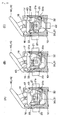
- Figs. 4A and 4B are perspective views showing the switch shown in Fig. 1 before and after operation;
- Figs. 5A, 5B, and 5C are horizontal, cross sectional views showing the switch shown in Fig. 1 before, during, and after operation;
- Figs. 6A and 6B are perspective views showing a base and contact terminals according to a second embodiment of the invention;
- Figs. 7A and 7B are perspective views showing a switch according to the second embodiment shown in Fig. 6 before and after operation;
- Figs. 8A, 8B, and 8C are plan views showing the switch shown in Fig. 6 before, during, and after operation;
- Figs. 9A, 9B, and 9C are horizontal, cross sectional views illustrating different methods of using the first, second, and third embodiments according to the invention;
- Figs. 10A, 10B, and 10C are horizontal, cross sectional views showing fourth, fifth, and sixth embodiments according to the invention; and
- Figs. 11A and 11B are a plan view and a cross sectional view illustrating different methods of using the fourth embodiment.
- Embodiments of the invention will be described below with reference to the accompanying drawings of Figs. 1 to 11.
- A first embodiment comprises, as shown in Figs. 1 to 5, a
base 10, into whichstationary contact terminals operating lever 40 supported pivotally on thebase 10, and acover 50 that covers thebase 10. In addition, an exemplary product as actually assembled has an outside dimension of a total height 0.9 mm, a base width of 3.0 mm, and a length of 3.5 mm. - The
base 10 comprises substantially U-shapedside walls 11, 12, 13 provided continuously and protrusively along a peripheral edge of an upper surface thereof, and thestationary contact terminals opposite side walls 11, 13.Positioning steps side walls 11, 13, on which thestationary contact terminals side walls 11, 13. Further, alow step 13b is formed on an inside edge of the upper surface of the side wall 13, on which thestationary contact terminal 21 is insert-molded, and alatch hole 14 is provided on thestep 13b to have anend 32 of the moving contact piece 30 latched thereon. A commonstationary contact 21a is exposed from an inner peripheral surface of thelatch hole 14. Also, a normally openedstationary contact 20a of thestationary contact terminal 20 is exposed from an inner surface of theside wall 11, on which thestationary contact terminal 20 is insert-molded. Further, thebase 10 comprisesspindles operating lever 40 described later, and a coming-offpreventive projection 18 protrusively provided between thespindles operating lever 40. - An
end 32 of the moving contact piece 30 made of a coil spring, which extends from an upper end of a coil portion 31 to be bent, is inserted into thelatch hole 14 of thebase 10 and pivotally supported and is press-contact with the commonstationary contact 21a. On the other hand, theother bent end 33 functioning as a moving contact can slide on the inner surface of theside wall 11 of thebase 10 and contact with the normally openedstationary contact 20a. The moving contact piece 30 is arranged so that the coil portion 31 slides on a bottom surface of thebase 10. - The
operating lever 40 comprises anaxial hole 41 positioned in a central position of a substantially sector shape in plan view and fitted rotatably onto thespindles base 10. An operating part 42 and adrive part 43 extend at a predetermined angle about theaxial hole 41, and anarcuate groove 45 about theaxial hole 41 is formed by connecting the operating part 42 and thedrive part 43 to each other by means of areinforcement rib 44. In addition, theaxial hole 41 of theoperating lever 40 can be fitted on either of thespindles base 10, and thedrive part 43 is shaped to be able to appropriately drive the moving contact piece 30 even in the case where theoperating lever 40 is supported by either of thespindles - The
cover 50 has a planar shape to enable covering thebase 10. However, an insulating sheet (not shown) may be stuck integrally to a roof surface of the cover at need. Thecover 50 is bent vertically from three adjacent outer peripheral edges to form engagement tongue pieces 51 (not shown), 52, 53, and bendable pawls 51a (not shown), 52a, 53a, respectively, are extended from lower end edges of thetongue pieces - Subsequently, an explanation will be given to a method of assembling the switch according to the embodiment.
- First, the
end 32 of the moving contact piece 30 is latched and supported pivotally on thelatch hole 14 of thebase 10, into whichstationary contact terminals base 10. Thereby, theend 32 of the moving contact piece 30 is brought into contact with the commonstationary contact 21a and theother end 33 can contact with the normally openedstationary contact 20a, while the coil portion 31 is placed slidably on the upper surface of the ridge 15. Theaxial hole 41 of the operatinglever 40 is fitted on, for example, thespindle 17 of the base 10 to be supported pivotally thereon. Then, thecover 50 is put on the base 10 to be pushed thereagainst whereby thetongue pieces 51, 53 and thetongue piece 52, respectively, are engaged by thepositioning steps lever 40 is pushed inward against the spring force of the moving contact piece 30 in this state, thedrive part 43 gets over the coming-offpreventive projection 18 and theprojection 18 is latched in thearcuate groove 45. Therefore, even when the operatinglever 40 is biased outward by the moving contact piece 30, it is prevented from coming off and theend 32 of the moving contact piece 30 is brought into pressure contact with the commonstationary contact 21a at a predetermined contact pressure. Thereafter, the assembling work is completed by inward by bending theengagement pawls tongue pieces cover 50 to thebase 10. - Subsequently, an explanation will be given to a method of operating the switch.
- In the case where any operating force is not exerted on the operating
lever 40, a spring force generated on the moving contact piece 30 by an action of beforehand loaded torsion causes theend 32 to be brought into pressure contact with the commonstationary contact 21a and theother end 33 to be brought into pressure contact with the inner surface of theside wall 11 at a predetermined contact pressure. - When the operating part 42 of the operating
lever 40 is pushed in, thedrive part 43 pushes the coil portion 31 as shown in Figs. 4 and 5. Therefore, a torsional moment acting on the coil portion 31 increases, so that the operatinglever 40 turns about thespindle 17 against the spring force of the moving contact piece 30 and theother end 33 slides on the inner surface of theside wall 11 to contact with the normally openedstationary contact 20a. - When a load on the operating
lever 40 is released, the operatinglever 40 is pushed back outward by the spring force of the moving contact piece 30. Therefore, the moving contact piece 30 turns about theend 32 of the moving contact piece 30 in a reverse direction to the direction described above, and theother end 33 thereof slides on thestationary contact 20a to effect opening. - According to the embodiment, the moving contact piece 30 turns deforming elastically to open and close the contact whereby a switch is obtained, which does not need as high part accuracy and assembly accuracy as those in the related art, and which is high in productivity and stable in operating characteristics.
- In particular, since the
other end 33 of the moving contact piece 30 moves sliding on thestationary contact 20a, an angle of torsion generated on the moving contact piece 30 is small as compared with the case where the other end does not move. Therefore, an internal stress generated on the moving contact piece 30 is small and fatigue failure is hard to occur. - Further, according to the embodiment, not only an operation in a counterclockwise direction but also an operation in a clockwise direction can be accommodated by fitting the operating
lever 40 onto thespindle 16. Therefore, since parts can be used in common, a single metallic mold can serve, thus enabling reduction in production cost. Consequently, according to the embodiment, there is an advantage that a switch capable of accommodating operation in three directions can be manufactured by a single kind of metallic mold. - A second embodiment provides a normally closed contact type, in which a normally closed
stationary contact 20b is arranged on aninner surface 11 of a base 10 as shown in Figs. 6 and 8. - That is, as shown in Fig. 6, a normally closed
stationary contact 20b is exposed to theinner surface 11 of thebase 10. As shown in Figs. 7 and 8, when an operatinglever 40 is pushed in, a torsional moment acting on a coil portion 31 increases, so that theother end 33 slides on the normally closedstationary contact 20b. When a load on the operatinglever 40 is released, the operatinglever 40 is pushed back outward by the spring force of the moving contact piece 30 to return to an original position. Since the rest is the same as that in the embodiment described above, the same parts as those in the latter are denoted by the same reference numerals as those in the latter, and an explanation therefor is omitted. - In addition, as shown in Fig. 9A and 9B the first embodiment and the second embodiment may be made clockwise by mounting the operating
lever 40 on thespindle 16. - According to a third embodiment, a normally closed
stationary contact 20a and a normally openedstationary contact 22a are exposed to an inner surface of aside wall 11. - Accordingly, when an operating
lever 40 is pushed in, a torsional moment acting on a coil portion 31 of a moving contact piece 30 increases, so that the moving contact piece 30 turns about anend 32. Therefore, after theother end 33 slides on the normally closedstationary contact 20a, it contacts with the normally openedstationary contact 21b to switch over the contact. Since the rest is the same as that in the embodiment described above, the same parts as those in the latter are denoted by the same reference numerals as those in the latter, and an explanation therefor is omitted. - According to a fourth embodiment, a normally opened
stationary contact 21b is arranged on a bottom surface of a base 10 as shown in Fig. 10A. - According to the embodiment, since the normally opened
stationary contact 21b is arranged on the bottom surface of thebase 10, a coil portion 31 of a moving contact piece 30 contacts with thestationary contact 21b at a constant contact pressure, so that there is an advantage that dispersion is hard to generate in operating characteristics. - The embodiment may be of course made counterclockwise by mounting the operating
lever 40 on thespindle 17 as shown in Fig. 11. - Also, a normally closed
stationary contact 21c may be arranged on a bottom surface of the base 10 as shown in Fig. 10B (a fifth embodiment) . Also, as shown in Fig. 10C, a normally closed stationary contact 20d and a normally openedstationary contact 21b may be arranged on a bottom surface of the base 10 (a sixth embodiment) . - Like the fourth embodiment described above, the fifth and sixth embodiments have an advantage that a switch can be obtained, in which dispersion in contact pressure is hard to generate and which has a stable operating characteristics.
- In addition, according to the embodiments, both an operation in a clockwise direction and an operation in a counterclockwise direction can be accommodated by changing a position, in which the operating
lever 40 is mounted to thebase 10. - Also, while according to the embodiments, an end of the moving contact piece extending from above is supported pivotally on the base, the other end thereof extending from under may be supported pivotally on the base.
- The switch according to the invention is of course applicable to a switch other than ones according to the embodiments.
Claims (8)
- A switch comprising a base, a moving contact piece made of a coil spring and having one end thereof, which is' supported pivotally on the base, coming into pressure contact with a common stationary contact, an operating lever having one end thereof supported pivotally on the base and having a drive part, which extends from the one end, pushing a coil portion of the moving contact piece, and a cover having a planar shape capable of covering the base and fixed to the base to compress the coil portion, and
wherein the operating lever pushes the coil portion of the moving contact piece to give thereto a torsional moment whereby the moving contact piece turns about an end thereof, the coil portion of the moving contact piece slides on a bottom surface of the base, and the other end of the moving contact piece slides on at least one stationary contact exposed from an inner surface of the base. - The switch according to claim 1, wherein the stationary contact exposed from the inner surface of the base comprises a normally opened stationary contact.
- The switch according to claim 1, wherein the stationary contact exposed from the inner surface of the base comprises a normally closed stationary contact.
- The switch according to claim 1, wherein the stationary contact exposed from the inner surface of the base comprises a normally opened stationary contact and a normally closed stationary contact.
- A switch comprising a base, a moving contact piece made of a coil spring and having one end thereof, which is supported pivotally on the base, coming into pressure contact with a common stationary contact, an operating lever having one end thereof supported pivotally on the base and having a drive part, which extends from the one end, pushing a coil portion of the moving contact piece, and a cover having a planar shape capable of covering the base and fixed to the base to compress the coil portion, and
wherein the operating lever pushes the coil portion of the moving contact piece to give thereto a torsional moment whereby the moving contact piece turns about an end thereof, the coil portion of the moving contact piece slides on at least one stationary contact exposed from a bottom surface of the base, and the other end of the moving contact piece slides on an inner surface of the base. - The switch according to claim 5, wherein the stationary contact exposed from the bottom surface of the base comprises a normally opened stationary contact.
- The switch according to claim 6, wherein the stationary contact exposed from the bottom surface of the base comprises a normally closed stationary contact.
- The switch according to claim 5, wherein the stationary contact exposed from the bottom surface of the base comprises a normally opened stationary contact and a normally closed stationary contact.
Applications Claiming Priority (1)
| Application Number | Priority Date | Filing Date | Title |
|---|---|---|---|
| JP2005134235A JP2006310229A (en) | 2005-05-02 | 2005-05-02 | Switch |
Publications (2)
| Publication Number | Publication Date |
|---|---|
| EP1720185A2 true EP1720185A2 (en) | 2006-11-08 |
| EP1720185A3 EP1720185A3 (en) | 2007-12-26 |
Family
ID=36845302
Family Applications (1)
| Application Number | Title | Priority Date | Filing Date |
|---|---|---|---|
| EP06008127A Withdrawn EP1720185A3 (en) | 2005-05-02 | 2006-04-19 | Switch |
Country Status (5)
| Country | Link |
|---|---|
| US (1) | US7223931B2 (en) |
| EP (1) | EP1720185A3 (en) |
| JP (1) | JP2006310229A (en) |
| KR (1) | KR100852839B1 (en) |
| CN (1) | CN1858877A (en) |
Families Citing this family (7)
| Publication number | Priority date | Publication date | Assignee | Title |
|---|---|---|---|---|
| JP4692410B2 (en) * | 2006-06-27 | 2011-06-01 | オムロン株式会社 | switch |
| JP5088264B2 (en) * | 2008-08-05 | 2012-12-05 | オムロン株式会社 | switch |
| JP5152380B1 (en) * | 2011-09-15 | 2013-02-27 | オムロン株式会社 | switch |
| JP5835037B2 (en) | 2012-03-14 | 2015-12-24 | オムロン株式会社 | switch |
| JP5906845B2 (en) * | 2012-03-15 | 2016-04-20 | オムロン株式会社 | switch |
| JP5867201B2 (en) * | 2012-03-15 | 2016-02-24 | オムロン株式会社 | switch |
| JP6213308B2 (en) * | 2014-02-28 | 2017-10-18 | オムロン株式会社 | switch |
Citations (5)
| Publication number | Priority date | Publication date | Assignee | Title |
|---|---|---|---|---|
| US5912445A (en) * | 1996-11-08 | 1999-06-15 | Matsushita Electric Works, Ltd. | Miniature pushbutton switch with coil spring contact |
| EP1261002A1 (en) * | 2000-10-31 | 2002-11-27 | Matsushita Electric Industrial Co., Ltd. | Small switch |
| US6768069B1 (en) * | 2003-04-08 | 2004-07-27 | Shin Jiuh Corp. | Micro switch |
| US6797904B1 (en) * | 2004-01-06 | 2004-09-28 | Zippy Technology Corp. | Microswitch |
| JP2004327115A (en) * | 2003-04-22 | 2004-11-18 | Smk Corp | Switch |
Family Cites Families (9)
| Publication number | Priority date | Publication date | Assignee | Title |
|---|---|---|---|---|
| JPH0660755A (en) * | 1992-08-06 | 1994-03-04 | Fujitsu Ltd | Small sized detection switch |
| JP3248392B2 (en) * | 1995-06-06 | 2002-01-21 | 松下電器産業株式会社 | Lever switch |
| JPH1021791A (en) | 1996-07-08 | 1998-01-23 | Alps Electric Co Ltd | Switch |
| JP4019601B2 (en) * | 2000-04-14 | 2007-12-12 | 松下電器産業株式会社 | Lever switch |
| JP3920012B2 (en) | 2000-07-28 | 2007-05-30 | アルプス電気株式会社 | Switch device |
| US6762379B1 (en) * | 2003-04-08 | 2004-07-13 | Shin Jiuh Corp. | Micro switch |
| JP2005116347A (en) * | 2003-10-08 | 2005-04-28 | Matsushita Electric Ind Co Ltd | Switch |
| JP4333332B2 (en) * | 2003-11-11 | 2009-09-16 | パナソニック株式会社 | switch |
| US6917008B1 (en) * | 2004-01-06 | 2005-07-12 | Zippy Technology Corp. | Microswitch |
-
2005
- 2005-05-02 JP JP2005134235A patent/JP2006310229A/en active Pending
-
2006
- 2006-04-19 EP EP06008127A patent/EP1720185A3/en not_active Withdrawn
- 2006-04-28 KR KR1020060038472A patent/KR100852839B1/en active IP Right Grant
- 2006-04-30 CN CNA2006100840391A patent/CN1858877A/en active Pending
- 2006-05-01 US US11/415,371 patent/US7223931B2/en not_active Expired - Fee Related
Patent Citations (5)
| Publication number | Priority date | Publication date | Assignee | Title |
|---|---|---|---|---|
| US5912445A (en) * | 1996-11-08 | 1999-06-15 | Matsushita Electric Works, Ltd. | Miniature pushbutton switch with coil spring contact |
| EP1261002A1 (en) * | 2000-10-31 | 2002-11-27 | Matsushita Electric Industrial Co., Ltd. | Small switch |
| US6768069B1 (en) * | 2003-04-08 | 2004-07-27 | Shin Jiuh Corp. | Micro switch |
| JP2004327115A (en) * | 2003-04-22 | 2004-11-18 | Smk Corp | Switch |
| US6797904B1 (en) * | 2004-01-06 | 2004-09-28 | Zippy Technology Corp. | Microswitch |
Also Published As
| Publication number | Publication date |
|---|---|
| KR100852839B1 (en) | 2008-08-18 |
| KR20060114635A (en) | 2006-11-07 |
| US20060246755A1 (en) | 2006-11-02 |
| EP1720185A3 (en) | 2007-12-26 |
| JP2006310229A (en) | 2006-11-09 |
| US7223931B2 (en) | 2007-05-29 |
| CN1858877A (en) | 2006-11-08 |
Similar Documents
| Publication | Publication Date | Title |
|---|---|---|
| US7223931B2 (en) | Switch | |
| EP2012333B1 (en) | Switch | |
| JP5596633B2 (en) | Switch device | |
| EP1873799B1 (en) | Switch | |
| EP1720186A2 (en) | Switch | |
| EP1918956A1 (en) | Switch | |
| EP1223593A2 (en) | Switch device | |
| KR100532341B1 (en) | Switch | |
| EP1918957A1 (en) | A surface-mounted switch | |
| JP4692404B2 (en) | Microswitch | |
| KR100606122B1 (en) | Switch | |
| KR100561292B1 (en) | Switch | |
| US9226417B2 (en) | Lock mechanism of electric connection box | |
| JP5317243B2 (en) | Switch device | |
| JP4457097B2 (en) | Side push type push switch | |
| JP4150380B2 (en) | Switch device | |
| JPH11144560A (en) | Push switch device |
Legal Events
| Date | Code | Title | Description |
|---|---|---|---|
| PUAI | Public reference made under article 153(3) epc to a published international application that has entered the european phase |
Free format text: ORIGINAL CODE: 0009012 |
|
| AK | Designated contracting states |
Kind code of ref document: A2 Designated state(s): AT BE BG CH CY CZ DE DK EE ES FI FR GB GR HU IE IS IT LI LT LU LV MC NL PL PT RO SE SI SK TR |
|
| AX | Request for extension of the european patent |
Extension state: AL BA HR MK YU |
|
| PUAL | Search report despatched |
Free format text: ORIGINAL CODE: 0009013 |
|
| AK | Designated contracting states |
Kind code of ref document: A3 Designated state(s): AT BE BG CH CY CZ DE DK EE ES FI FR GB GR HU IE IS IT LI LT LU LV MC NL PL PT RO SE SI SK TR |
|
| AX | Request for extension of the european patent |
Extension state: AL BA HR MK YU |
|
| RIC1 | Information provided on ipc code assigned before grant |
Ipc: H01H 21/14 20060101ALN20071119BHEP Ipc: H01H 21/12 20060101ALN20071119BHEP Ipc: H01H 1/40 20060101ALN20071119BHEP Ipc: H01H 1/24 20060101ALN20071119BHEP Ipc: H01H 1/44 20060101ALN20071119BHEP Ipc: H01H 21/24 20060101ALI20071119BHEP Ipc: H01H 1/36 20060101ALI20071119BHEP Ipc: H01H 21/28 20060101AFI20060829BHEP |
|
| AKX | Designation fees paid | ||
| STAA | Information on the status of an ep patent application or granted ep patent |
Free format text: STATUS: THE APPLICATION IS DEEMED TO BE WITHDRAWN |
|
| 18D | Application deemed to be withdrawn |
Effective date: 20080627 |
|
| REG | Reference to a national code |
Ref country code: DE Ref legal event code: 8566 |