EP1719941A1 - Pipe joint - Google Patents
Pipe joint Download PDFInfo
- Publication number
- EP1719941A1 EP1719941A1 EP05710569A EP05710569A EP1719941A1 EP 1719941 A1 EP1719941 A1 EP 1719941A1 EP 05710569 A EP05710569 A EP 05710569A EP 05710569 A EP05710569 A EP 05710569A EP 1719941 A1 EP1719941 A1 EP 1719941A1
- Authority
- EP
- European Patent Office
- Prior art keywords
- pipe
- coupling
- resin
- tip end
- base body
- Prior art date
- Legal status (The legal status is an assumption and is not a legal conclusion. Google has not performed a legal analysis and makes no representation as to the accuracy of the status listed.)
- Granted
Links
Images

Classifications
-
- F—MECHANICAL ENGINEERING; LIGHTING; HEATING; WEAPONS; BLASTING
- F16—ENGINEERING ELEMENTS AND UNITS; GENERAL MEASURES FOR PRODUCING AND MAINTAINING EFFECTIVE FUNCTIONING OF MACHINES OR INSTALLATIONS; THERMAL INSULATION IN GENERAL
- F16L—PIPES; JOINTS OR FITTINGS FOR PIPES; SUPPORTS FOR PIPES, CABLES OR PROTECTIVE TUBING; MEANS FOR THERMAL INSULATION IN GENERAL
- F16L37/00—Couplings of the quick-acting type
- F16L37/08—Couplings of the quick-acting type in which the connection between abutting or axially overlapping ends is maintained by locking members
- F16L37/084—Couplings of the quick-acting type in which the connection between abutting or axially overlapping ends is maintained by locking members combined with automatic locking
- F16L37/091—Couplings of the quick-acting type in which the connection between abutting or axially overlapping ends is maintained by locking members combined with automatic locking by means of a ring provided with teeth or fingers
- F16L37/0915—Couplings of the quick-acting type in which the connection between abutting or axially overlapping ends is maintained by locking members combined with automatic locking by means of a ring provided with teeth or fingers with a separate member for releasing the coupling
-
- F—MECHANICAL ENGINEERING; LIGHTING; HEATING; WEAPONS; BLASTING
- F16—ENGINEERING ELEMENTS AND UNITS; GENERAL MEASURES FOR PRODUCING AND MAINTAINING EFFECTIVE FUNCTIONING OF MACHINES OR INSTALLATIONS; THERMAL INSULATION IN GENERAL
- F16L—PIPES; JOINTS OR FITTINGS FOR PIPES; SUPPORTS FOR PIPES, CABLES OR PROTECTIVE TUBING; MEANS FOR THERMAL INSULATION IN GENERAL
- F16L2201/00—Special arrangements for pipe couplings
- F16L2201/10—Indicators for correct coupling
Definitions
- the present invention relates to an improvement of a pipe coupling. More particularly, the present invention relates to a pipe coupling with which it can be easily determined whether or not a pipe is fully inserted into the coupling.
- a flexible pipe (hereinafter, referred to simply as a "pipe"), which is formed of a resin such as polybutene or cross-linked polyethylene, is used as a water or hot water-supply pipe in a multiple dwelling house or a single house.
- a coupling including an O-ring that contacts the surface of the pipe to block water; and a pipe holding member (hereinafter, referred to simply as a “holding member”) that bites into an outer surface of the pipe to prevent removal of the pipe from the coupling when a water pressure is applied thereto, is used (Patent Document 1).
- Patent Document 2 Japanese Patent Application ( JP-A) No. 11-118081
- Patent Document 2 Japanese Patent Application No. 2002-5373
- an object of the present invention is to provide a pipe coupling with which it can be easily determined whether or not a pipe is fully inserted into a coupling.
- the invention relates to a pipe coupling comprising an O-ring that is brought into contact with a surface of a pipe to block water; and a pipe holding member that bites into an outer surface of the pipe to prevent removal of the pipe from the coupling when water pressure is applied thereto, wherein a portion of the pipe coupling that corresponds to a tip end position of the pipe when the pipe is fully inserted into the pipe coupling is formed of a resin which has high transparency and through which the tip end of the pipe can be visually observed.
- the invention relates to a pipe coupling comprising a coupling base body, an inner cylinder that extends from the coupling base body and is fitted into an inner circumference of the pipe, an O-ring that is fitted onto the outer surface of the inner cylinder, a transparent resin collar that corresponds to a tip end position of the pipe when the pipe is fully inserted into the inner cylinder, is fixed to the coupling base body, and through which the tip end of the pipe can be visually observed, a pipe holding member disposed at the tip end of the resin collar to hold the pipe, a pipe release ring disposed at the tip end of the resin collar, and a sleeve that is attached to the resin collar so as to cover at least a portion of the resin collar, the pipe holding member and the pipe release ring.
- At least a portion of a pipe coupling corresponding to a tip end position of the pipe inserted into the coupling is formed of a transparent resin. Therefore, an operator can easily determine whether or not the pipe is fully inserted into the coupling through a visual observation. Accordingly, the occurrence of water leakage due to operational mistakes can be reduced.
- the invention achieved a pipe coupling enabling visual confirmation of whether or not a pipe inserted into the coupling is inserted to a predetermined position.
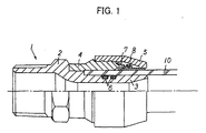
- Fig. 1 shows a lateral cross-sectional view of such a pipe coupling 1
- Fig. 2 shows an exploded view thereof
- reference numeral 2 denotes a pipe coupling base body
- 3 denotes an inner cylinder extending from the pipe coupling base body
- 4 denotes a cylindrical resin collar
- 5 denotes a sleeve.
- the pipe coupling base body 2 and the inner cylinder 3 are formed of gun metal
- the resin collar 4 is a transparent collar which is formed by TROGAMID CX7323.
- the sleeve 5 is formed of polyacetal.
- the pipe coupling base body 2 and the resin collar 4 are usually fixed to each other by press-fitting, and the resin collar 4 and the sleeve 5 are fixed to each other by press-fitting (screwed together if needed).
- reference numeral 10 denotes a pipe.
- a pipe holding member denoted by reference numeral 7, bites into an outer surface of the pipe 10 and has a pawl that can prevent removal of the pipe 10 from the pipe coupling 1.
- reference numeral 8 denotes a pipe release ring which is used for pulling out the pipe 10.
- the inner cylinder 3 is inserted into the pipe 10 and the tip end of the pipe 10 rides over the O-ring 6. Then, when the pipe 10 is further inserted into the coupling, the tip end of the pipe 10 can be visually observed through the resin collar 4. By this, it is confirmed that the tip end of the pipe 10 has reached a step portion 3b which is formed at the deepest portion of the inner cylinder 3, and full insertion of the pipe 10 into the coupling 1 can be visually observed.
- press fit interference (%) is represented by an expression of ⁇ (A-B)/B ⁇ 100, and a press fit interference of from 3 to 5% can satisfy conditions such as tensional performance and hot internal pressure creep property required for the coupling.
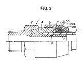
- Fig. 3 shows a lateral cross-sectional view of another example of the pipe coupling 1 according to an embodiment of the present invention.
- the present embodiment is basically structured in the same manner as in the first embodiment except for the following respects.
- reference numeral 2 denotes a pipe coupling base body
- 3 denotes an inner cylinder extending from the pipe coupling base body
- 4 denotes a cylindrical resin collar
- 5 denotes a sleeve.
- reference numeral 20 denotes an inclined wall which is formed at an inner circumference of the sleeve 5
- 20a denotes a step portion which is formed at the inclined wall 20.
- a metal protection ring 30 is attached to the step portion 20a.
- the pipe coupling base body 2 is formed into a substantially U shape as seen from a side view, to cover an upper surface of the resin collar 4 (i.e., the upper side surface of the resin collar 4 in Fig. 3). Namely, when the pipe coupling base body 2 and the resin collar 4 are fitted to each other by press-fitting, a portion of the resin collar 4 is structured to fit into a concave portion of the pipe coupling base body 2. Accordingly, protection of the resin collar 4 as well as the total strength of the pipe coupling 1 can be enhanced.
- the O-ring 6 is fit into the circumferential grooves formed on the surface of the inner cylinder 3.
- reference numeral 8 denotes a pipe release ring which is used for pulling out the pipe 10.
- the protection ring 30 is attached to the step portion 20a of the inclined wall 20 of the sleeve 5, when the pipe 10 is pulled from the pipe coupling 1 in a direction in which the pipe 10 is pulled out (in a right-hand direction of Fig. 3), the pipe holding member 7 and the pipe release ring 8 abut with each other and move, together with the pipe 10, in the direction in which the pipe 10 is pulled out.
- the outer circumferential inclined surface of the pipe holding member 7 abuts with the protection ring 30, and does not contact the inner circumferential inclined surface of the sleeve 5. Accordingly, even if the sleeve 5 is formed of a resin, damage caused to the inner circumferential inclined surface 20 can be prevented.
- the invention can provide a pipe coupling which enables visual confirmation of whether or not the pipe inserted into the coupling is inserted to a predetermined position. Therefore, the invention has a specific structure such that a transparent ring-shaped resin collar, which corresponds to a tip end position of the pipe to provide a visual observation, is built into the pipe coupling. Although the entire coupling can certainly be formed of a resin having high transparency, the greatest effect of the present invention is that the tip end of the pipe can be visually observed through the coupling.
- a sealing mechanism generally uses an O-ring.
- either of the inner surface or the outer surface of the pipe which is to be inserted can be used for sealing.
- the above-described Example is a more specific example of a structure in which the inner surface of the pipe is used for sealing.
- Such a pipe coupling is usually formed of a metal or a resin.
- pipe couplings formed of a resin can also be employed.
- Such pipe couplings can be obtained by injection molding of a resin such as a PPS resin, a polybutene resin or a PP resin.
- the material used for visual observation is manufactured using a transparent resin. Therefore, in order to fix a coupling base body and a resin having high transparency to each other, press-fitting is generally used. However, press fit interference of at least 3 to 5% is needed to satisfy the strength of, for example, tensional performance or hot internal pressure creep property. Accordingly, it is found that a material having transparency used herein should, in particular, have a yield point elongation of 5% or more, and preferably 7%. Considering this point, a resin material reinforced by glass or the like suffers a significant drawback because such a material has poor elongation, and may crack easily during a press-fitting operation. Generally, cracks may occur at a yield point elongation of 2 to 3%.
- transparent resins include resins having heat resistance and transparency such as PPSU (polyphenyl sulfone), PES (polyether sulfone), denatured PPE (denatured polyphenylene ether), PEI (polyether imide) and PC (polycarbonate).
- PPSU polyphenyl sulfone
- PES polyether sulfone
- denatured PPE denatured polyphenylene ether
- PEI polyether imide
- PC polycarbonate
- a micro-crystalline polyamide resin is selected as a resin for satisfying design requirements particularly required for transparent resins, such as elongation of material and resistance to stress cracking, and more specifically, as a resin for satisfying tensional performance and hot internal pressure creep property with a large yield point elongation (6% or more) and a press fit interference of 3 to 5%.
- the micro-crystalline polyimide resin is capable of preventing occurrence of ESC, and satisfying all the performances required from standpoints of elongation at the time of press-fitting, transparency, resistance to hot internal pressure creep property, and resistance to ESC. Description of the press fit interference will be made later.
- a specific example of a micro-crystalline polyamide which is suitable for the transparent resin of the invention is a polyamide resin (Trogamide CX7323) manufactured by Daicel-Degussa Ltd.
- This resin is colorless and transparent and is extremely excellent in chemical resistance, impact resistance, climate resistance, and dimensional stability, and is generally formed by an injection molding, such that all the requirements for the pipe coupling are satisfied.
- micro-crystalline polyamide in particular is preferable is described below. That is, although resins such as PSU (polysulfone), PPSU, PES and PPE are non-colored and transparent, they exhibit amber color or the like in a natural state. On the other hand, micro-crystalline polyamide is colorless and transparent in a non-colored state thus making it easy to recognize the color of a pipe and preventing the pipe from being mistaken as the inner cylinder or the like of the coupling main body. Accordingly, it can be said that micro-crystalline polyamide is a more suitable resin for confirming states of use in the field.
- resins such as PSU (polysulfone), PPSU, PES and PPE are non-colored and transparent, they exhibit amber color or the like in a natural state.
- micro-crystalline polyamide is colorless and transparent in a non-colored state thus making it easy to recognize the color of a pipe and preventing the pipe from being mistaken as the inner cylinder or the like of the coupling main body. Accordingly, it
- the pipe coupling of the present invention enables the insertion of a pipe into the coupling to be visually observed, is applicable to couplings for pipes formed of a resin as well as those formed of various other materials, and can be used in an extremely wide range of applications.
Landscapes
- Engineering & Computer Science (AREA)
- General Engineering & Computer Science (AREA)
- Mechanical Engineering (AREA)
- Quick-Acting Or Multi-Walled Pipe Joints (AREA)
- Branch Pipes, Bends, And The Like (AREA)
- Joints With Sleeves (AREA)
Abstract
Description
- The present invention relates to an improvement of a pipe coupling. More particularly, the present invention relates to a pipe coupling with which it can be easily determined whether or not a pipe is fully inserted into the coupling.
- In recent years, a technique has been developed in which a flexible pipe (hereinafter, referred to simply as a "pipe"), which is formed of a resin such as polybutene or cross-linked polyethylene, is used as a water or hot water-supply pipe in a multiple dwelling house or a single house. In order to connect such a pipe to a header or various types of tool, a coupling including an O-ring that contacts the surface of the pipe to block water; and a pipe holding member (hereinafter, referred to simply as a "holding member") that bites into an outer surface of the pipe to prevent removal of the pipe from the coupling when a water pressure is applied thereto, is used (Patent Document 1).
- However, since the holding member as well as the O-ring must be kept in tight contact with the surface of the pipe, a relatively high resistance to insertion is generated when the pipe is inserted into the coupling. Therefore, if the resistance to insertion is large, a case may occur in which the pipe is mistakenly thought to be fully inserted into the coupling, and used without in fact being fully inserted into the coupling. Such an imperfect insertion of the pipe may be a major factor causing water leakage.
- Although field workers are always warned to pay due attention in this regard, the problem remains in evidence. In this respect, there have been cases in which the outer surface of a pipe is marked with an indicator line showing the length between the tip end position and the insertion position of the pipe. However, this has not eliminated mistakes.
- Therefore, a pipe coupling through which the insertion of a pipe can be visually observed has been developed. However, description has mainly been made of observation holes in the pipe coupling and no description has been made of a specific example of a resin collar (Patent Document 2).
Patent Document 1: Japanese Patent Application (JP-A) No. 11-118081
Patent Document 2:Japanese Patent Application No. 2002-5373 - In order to solve the aforementioned drawbacks, an object of the present invention is to provide a pipe coupling with which it can be easily determined whether or not a pipe is fully inserted into a coupling.
- In order to solve the aforementioned problems, the invention is constituted as described below. That is, the invention relates to a pipe coupling comprising an O-ring that is brought into contact with a surface of a pipe to block water; and a pipe holding member that bites into an outer surface of the pipe to prevent removal of the pipe from the coupling when water pressure is applied thereto, wherein a portion of the pipe coupling that corresponds to a tip end position of the pipe when the pipe is fully inserted into the pipe coupling is formed of a resin which has high transparency and through which the tip end of the pipe can be visually observed.
- More specifically, the invention relates to a pipe coupling comprising a coupling base body, an inner cylinder that extends from the coupling base body and is fitted into an inner circumference of the pipe, an O-ring that is fitted onto the outer surface of the inner cylinder, a transparent resin collar that corresponds to a tip end position of the pipe when the pipe is fully inserted into the inner cylinder, is fixed to the coupling base body, and through which the tip end of the pipe can be visually observed, a pipe holding member disposed at the tip end of the resin collar to hold the pipe, a pipe release ring disposed at the tip end of the resin collar, and a sleeve that is attached to the resin collar so as to cover at least a portion of the resin collar, the pipe holding member and the pipe release ring.
- In accordance with the invention, at least a portion of a pipe coupling corresponding to a tip end position of the pipe inserted into the coupling is formed of a transparent resin. Therefore, an operator can easily determine whether or not the pipe is fully inserted into the coupling through a visual observation. Accordingly, the occurrence of water leakage due to operational mistakes can be reduced.
-
- [Fig. 1] Fig. 1 is a lateral cross-sectional view of a pipe coupling according to one embodiment of the present invention.
- [Fig. 2] Fig. 2 is an exploded cross-sectional view of Fig. 1.
- [Fig. 3] Fig. 3 is a lateral cross-sectional view of a pipe coupling according to another embodiment of the present invention.
- The invention achieved a pipe coupling enabling visual confirmation of whether or not a pipe inserted into the coupling is inserted to a predetermined position.
- Hereinafter, with reference to drawings, a pipe coupling according to an embodiment of the present invention will be explained.
- Fig. 1 shows a lateral cross-sectional view of such a pipe coupling 1, and Fig. 2 shows an exploded view thereof, wherein
reference numeral 2 denotes a pipe coupling base body, 3 denotes an inner cylinder extending from the pipe coupling base body, 4 denotes a cylindrical resin collar, and 5 denotes a sleeve. The pipecoupling base body 2 and theinner cylinder 3 are formed of gun metal, and theresin collar 4 is a transparent collar which is formed by TROGAMID CX7323. Thesleeve 5 is formed of polyacetal. - The pipe
coupling base body 2 and theresin collar 4 are usually fixed to each other by press-fitting, and theresin collar 4 and thesleeve 5 are fixed to each other by press-fitting (screwed together if needed). Further,reference numeral 10 denotes a pipe. - On the surface of the
inner cylinder 3 are formed twocircumferential grooves 3a into which an O-ring 6 is fitted. A pipe holding member, denoted byreference numeral 7, bites into an outer surface of thepipe 10 and has a pawl that can prevent removal of thepipe 10 from the pipe coupling 1. Further,reference numeral 8 denotes a pipe release ring which is used for pulling out thepipe 10. By pushing thepipe release ring 8 inward of the pipe coupling 1, a state in which the pawl of thepipe holding member 7 bites into the outer surface of the pipe is cancelled, and the pipe is then pulled out with this state maintained. - The
inner cylinder 3 is inserted into thepipe 10 and the tip end of thepipe 10 rides over the O-ring 6. Then, when thepipe 10 is further inserted into the coupling, the tip end of thepipe 10 can be visually observed through theresin collar 4. By this, it is confirmed that the tip end of thepipe 10 has reached astep portion 3b which is formed at the deepest portion of theinner cylinder 3, and full insertion of thepipe 10 into the coupling 1 can be visually observed. - Here, press fit interference (%) is represented by an expression of {(A-B)/B}×100, and a press fit interference of from 3 to 5% can satisfy conditions such as tensional performance and hot internal pressure creep property required for the coupling.
- Another example of the pipe coupling 1 according to an embodiment of the present invention will be explained next. Structures and operations identical to those in the first embodiment are denoted by the same reference numerals, and description thereof will be omitted.
- Fig. 3 shows a lateral cross-sectional view of another example of the pipe coupling 1 according to an embodiment of the present invention. The present embodiment is basically structured in the same manner as in the first embodiment except for the following respects.
- In the same manner as in the first embodiment described above,
reference numeral 2 denotes a pipe coupling base body, 3 denotes an inner cylinder extending from the pipe coupling base body, 4 denotes a cylindrical resin collar, and 5 denotes a sleeve. Further,reference numeral 20 denotes an inclined wall which is formed at an inner circumference of thesleeve inclined wall 20. Ametal protection ring 30 is attached to thestep portion 20a. - In the present embodiment, the pipe
coupling base body 2 is formed into a substantially U shape as seen from a side view, to cover an upper surface of the resin collar 4 (i.e., the upper side surface of theresin collar 4 in Fig. 3). Namely, when the pipecoupling base body 2 and theresin collar 4 are fitted to each other by press-fitting, a portion of theresin collar 4 is structured to fit into a concave portion of the pipecoupling base body 2. Accordingly, protection of theresin collar 4 as well as the total strength of the pipe coupling 1 can be enhanced. - The O-
ring 6 is fit into the circumferential grooves formed on the surface of theinner cylinder 3. A pipe holding member, denoted byreference numeral 7, bites into the outer surface of thepipe 10, and has a pawl that can prevent removal of thepipe 10 from the pipe coupling 1. - Further,
reference numeral 8 denotes a pipe release ring which is used for pulling out thepipe 10. By pushing thepipe release ring 8 inward of the pipe coupling 1, a state in which the pawl of thepipe holding member 7 bites into the outer surface of the pipe is cancelled, and the pipe is then pulled out with this state maintained. - Further, since the
protection ring 30 is attached to thestep portion 20a of theinclined wall 20 of thesleeve 5, when thepipe 10 is pulled from the pipe coupling 1 in a direction in which thepipe 10 is pulled out (in a right-hand direction of Fig. 3), thepipe holding member 7 and thepipe release ring 8 abut with each other and move, together with thepipe 10, in the direction in which thepipe 10 is pulled out. However, the outer circumferential inclined surface of thepipe holding member 7 abuts with theprotection ring 30, and does not contact the inner circumferential inclined surface of thesleeve 5. Accordingly, even if thesleeve 5 is formed of a resin, damage caused to the inner circumferentialinclined surface 20 can be prevented. - Other portions are identical to those in Fig. 1, and description thereof will be omitted.
- As described above, the invention can provide a pipe coupling which enables visual confirmation of whether or not the pipe inserted into the coupling is inserted to a predetermined position. Therefore, the invention has a specific structure such that a transparent ring-shaped resin collar, which corresponds to a tip end position of the pipe to provide a visual observation, is built into the pipe coupling. Although the entire coupling can certainly be formed of a resin having high transparency, the greatest effect of the present invention is that the tip end of the pipe can be visually observed through the coupling.
- In the present invention, a sealing mechanism generally uses an O-ring. However, either of the inner surface or the outer surface of the pipe which is to be inserted can be used for sealing. The above-described Example is a more specific example of a structure in which the inner surface of the pipe is used for sealing.
- Such a pipe coupling is usually formed of a metal or a resin. However, from the standpoints of light weight, easiness to mold or cost performance, pipe couplings formed of a resin can also be employed. Such pipe couplings can be obtained by injection molding of a resin such as a PPS resin, a polybutene resin or a PP resin.
- The material used for visual observation is manufactured using a transparent resin. Therefore, in order to fix a coupling base body and a resin having high transparency to each other, press-fitting is generally used. However, press fit interference of at least 3 to 5% is needed to satisfy the strength of, for example, tensional performance or hot internal pressure creep property. Accordingly, it is found that a material having transparency used herein should, in particular, have a yield point elongation of 5% or more, and preferably 7%. Considering this point, a resin material reinforced by glass or the like suffers a significant drawback because such a material has poor elongation, and may crack easily during a press-fitting operation. Generally, cracks may occur at a yield point elongation of 2 to 3%.
- Examples of transparent resins include resins having heat resistance and transparency such as PPSU (polyphenyl sulfone), PES (polyether sulfone), denatured PPE (denatured polyphenylene ether), PEI (polyether imide) and PC (polycarbonate). Among these non-crystalline resins, for example, PPSU is used as necessary. However, there is a concern that ESC (Environmental Stress Cracking) may occur due to a combined action of stress within the PPSU resin and a surfactant component contained in a lubricant used in field applications.
- A micro-crystalline polyamide resin is selected as a resin for satisfying design requirements particularly required for transparent resins, such as elongation of material and resistance to stress cracking, and more specifically, as a resin for satisfying tensional performance and hot internal pressure creep property with a large yield point elongation (6% or more) and a press fit interference of 3 to 5%. Namely, the micro-crystalline polyimide resin is capable of preventing occurrence of ESC, and satisfying all the performances required from standpoints of elongation at the time of press-fitting, transparency, resistance to hot internal pressure creep property, and resistance to ESC. Description of the press fit interference will be made later.
- A specific example of a micro-crystalline polyamide which is suitable for the transparent resin of the invention is a polyamide resin (Trogamide CX7323) manufactured by Daicel-Degussa Ltd. This resin is colorless and transparent and is extremely excellent in chemical resistance, impact resistance, climate resistance, and dimensional stability, and is generally formed by an injection molding, such that all the requirements for the pipe coupling are satisfied.
- The reason that micro-crystalline polyamide in particular is preferable is described below. That is, although resins such as PSU (polysulfone), PPSU, PES and PPE are non-colored and transparent, they exhibit amber color or the like in a natural state. On the other hand, micro-crystalline polyamide is colorless and transparent in a non-colored state thus making it easy to recognize the color of a pipe and preventing the pipe from being mistaken as the inner cylinder or the like of the coupling main body. Accordingly, it can be said that micro-crystalline polyamide is a more suitable resin for confirming states of use in the field.
- The pipe coupling of the present invention enables the insertion of a pipe into the coupling to be visually observed, is applicable to couplings for pipes formed of a resin as well as those formed of various other materials, and can be used in an extremely wide range of applications.
Claims (5)
- A pipe coupling comprising:an O-ring that contacts a surface of a pipe to block water; anda pipe holding member that bites into an outer surface of the pipe to prevent removal of the pipe from the coupling when water pressure is applied thereto,wherein a portion of the pipe coupling that corresponds to a tip end position of the pipe when the pipe is fully inserted into the pipe coupling, is formed of a resin that has high transparency and through which the tip end of the pipe can be visually observed.
- A pipe coupling comprising:a coupling base body;an inner cylinder that extends from the coupling base body and that is fitted into an inner circumference of a pipe;an O-ring that is fitted onto an outer surface of the inner cylinder;a transparent resin collar that corresponds to a tip end position of the pipe when the pipe is fully inserted into the inner cylinder, is fixed to the coupling base body, and through which the tip end of the pipe can be visually observed;a pipe holding member disposed at the tip end of the resin collar to hold the pipe;a pipe release ring disposed at the tip end of the resin collar; anda sleeve that is attached to the resin collar so as to cover at least a portion of the resin collar, the pipe holding member and the pipe release ring.
- The pipe coupling according to claim 1 or 2, wherein a yield point elongation of the resin having high transparency is 5% or more.
- The pipe coupling according to any one of claims 1 to 3, wherein the resin having high transparency is micro-crystalline polyamide.
- The pipe coupling according to claim 2, wherein the coupling base body is formed of a PPS resin.
Applications Claiming Priority (2)
| Application Number | Priority Date | Filing Date | Title |
|---|---|---|---|
| JP2004046239 | 2004-02-23 | ||
| PCT/JP2005/002876 WO2005080854A1 (en) | 2004-02-23 | 2005-02-23 | Pipe joint |
Publications (3)
| Publication Number | Publication Date |
|---|---|
| EP1719941A1 true EP1719941A1 (en) | 2006-11-08 |
| EP1719941A4 EP1719941A4 (en) | 2009-09-23 |
| EP1719941B1 EP1719941B1 (en) | 2011-08-10 |
Family
ID=34879435
Family Applications (1)
| Application Number | Title | Priority Date | Filing Date |
|---|---|---|---|
| EP05710569A Ceased EP1719941B1 (en) | 2004-02-23 | 2005-02-23 | Pipe joint |
Country Status (4)
| Country | Link |
|---|---|
| EP (1) | EP1719941B1 (en) |
| JP (1) | JP4956183B2 (en) |
| CN (1) | CN100427819C (en) |
| WO (1) | WO2005080854A1 (en) |
Cited By (6)
| Publication number | Priority date | Publication date | Assignee | Title |
|---|---|---|---|---|
| NL1036410C2 (en) * | 2009-01-12 | 2010-07-13 | Wavin Bv | Push-fit pipe connector with improved gripping assembly. |
| GB2486004A (en) * | 2010-12-01 | 2012-06-06 | Gordon Leonard Meyers | A light-transmissible pipe coupling |
| JP2012219997A (en) * | 2011-04-14 | 2012-11-12 | Hitachi Metals Ltd | Insertion-type pipe joint |
| EP2320118A4 (en) * | 2008-07-11 | 2012-12-26 | Lin Wai Lai | Fluid pipe connection device |
| EP2322835A4 (en) * | 2008-08-05 | 2013-05-08 | Nippon Pillar Packing | TUBULAR RESIN FITTING |
| EP2615348A3 (en) * | 2012-01-13 | 2016-07-06 | Comap | Fast coupling |
Families Citing this family (4)
| Publication number | Priority date | Publication date | Assignee | Title |
|---|---|---|---|---|
| JP5452947B2 (en) * | 2009-02-18 | 2014-03-26 | 株式会社ブリヂストン | Pipe fittings |
| JP5227852B2 (en) * | 2009-03-09 | 2013-07-03 | 株式会社オンダ製作所 | Fitting |
| IT1394209B1 (en) * | 2009-05-06 | 2012-06-01 | Saipem Spa | TUBE BAND EQUIPMENT WITH LIQUID FLOW REGULATOR ELEMENTS |
| JP2012225414A (en) * | 2011-04-19 | 2012-11-15 | Bridgestone Corp | Composite tube and composite tube connection structure |
Family Cites Families (12)
| Publication number | Priority date | Publication date | Assignee | Title |
|---|---|---|---|---|
| EP0224188B1 (en) * | 1985-11-28 | 1989-11-02 | Mitsui & Co., Ltd. | A seal joint structure |
| JPH10220665A (en) * | 1997-02-05 | 1998-08-21 | Fujipura Seiko Co Ltd | Rapid joint provided with body making mounted end part of pipe visible |
| DE19854148A1 (en) * | 1998-11-24 | 2000-11-02 | Friatec Ag | Plug-in coupling |
| JP2001021087A (en) * | 1999-07-08 | 2001-01-26 | Sekisui Chem Co Ltd | Pipe fittings |
| JP2001159492A (en) * | 1999-12-01 | 2001-06-12 | Onda Seisakusho:Kk | Joint |
| DE10009756B4 (en) * | 2000-03-01 | 2004-03-25 | Ems-Chemie Ag | Colorless, highly transparent polyamide blends with improved stress crack resistance |
| JP4564679B2 (en) * | 2000-04-21 | 2010-10-20 | ブリヂストンフローテック株式会社 | Pipe fitting |
| JP2002156080A (en) * | 2000-11-17 | 2002-05-31 | Mym Corp | Erroneous connection prevention pipe joint |
| JP3747784B2 (en) * | 2001-02-01 | 2006-02-22 | 東海ゴム工業株式会社 | Resin connector |
| JP2002310364A (en) * | 2001-04-18 | 2002-10-23 | Toyox Co Ltd | One-touch fitting |
| JP2002357295A (en) * | 2001-06-04 | 2002-12-13 | Sekisui Chem Co Ltd | Pipe fittings |
| JP2003343783A (en) * | 2002-05-23 | 2003-12-03 | Nasco Fitting Kk | Pipe joint |
-
2005
- 2005-02-23 EP EP05710569A patent/EP1719941B1/en not_active Ceased
- 2005-02-23 JP JP2006510288A patent/JP4956183B2/en not_active Expired - Lifetime
- 2005-02-23 WO PCT/JP2005/002876 patent/WO2005080854A1/en not_active Ceased
- 2005-02-23 CN CNB2005800057579A patent/CN100427819C/en not_active Expired - Fee Related
Cited By (11)
| Publication number | Priority date | Publication date | Assignee | Title |
|---|---|---|---|---|
| EP2320118A4 (en) * | 2008-07-11 | 2012-12-26 | Lin Wai Lai | Fluid pipe connection device |
| EP2322835A4 (en) * | 2008-08-05 | 2013-05-08 | Nippon Pillar Packing | TUBULAR RESIN FITTING |
| EP2698572A1 (en) * | 2008-08-05 | 2014-02-19 | Nippon Pillar Packing Co., Ltd. | Resinous tube joint |
| US9222608B2 (en) | 2008-08-05 | 2015-12-29 | Nippon Pillar Packing Co., Ltd. | Resinous tube joint |
| NL1036410C2 (en) * | 2009-01-12 | 2010-07-13 | Wavin Bv | Push-fit pipe connector with improved gripping assembly. |
| WO2010080027A1 (en) * | 2009-01-12 | 2010-07-15 | Wavin B.V. | Push-fit pipe connector with improved gripping assembly |
| RU2507434C2 (en) * | 2009-01-12 | 2014-02-20 | Вавин Б.В. | Plug-in pipe connector with improved clamping assembly |
| GB2486004A (en) * | 2010-12-01 | 2012-06-06 | Gordon Leonard Meyers | A light-transmissible pipe coupling |
| GB2486004B (en) * | 2010-12-01 | 2015-09-30 | Gordon Leonard Meyers | Light-transmissable pipe coupling |
| JP2012219997A (en) * | 2011-04-14 | 2012-11-12 | Hitachi Metals Ltd | Insertion-type pipe joint |
| EP2615348A3 (en) * | 2012-01-13 | 2016-07-06 | Comap | Fast coupling |
Also Published As
| Publication number | Publication date |
|---|---|
| JPWO2005080854A1 (en) | 2008-03-06 |
| WO2005080854A1 (en) | 2005-09-01 |
| EP1719941A4 (en) | 2009-09-23 |
| CN100427819C (en) | 2008-10-22 |
| JP4956183B2 (en) | 2012-06-20 |
| CN1922430A (en) | 2007-02-28 |
| EP1719941B1 (en) | 2011-08-10 |
Similar Documents
| Publication | Publication Date | Title |
|---|---|---|
| US9228681B2 (en) | Pipe coupling | |
| US7845685B2 (en) | Instant coupling device with locking and/or disconnection means | |
| CN101896755B (en) | Connection structure of tubular connection member and joint member | |
| EP1719941A1 (en) | Pipe joint | |
| CN105849452A (en) | Connector, release tool and device comprising connector and release tool | |
| AU2010261529B2 (en) | Push-fit pipe fitting system with support sleeve | |
| US9664324B2 (en) | Containment pipe fittings and methods | |
| JP6515231B1 (en) | Pipe fitting | |
| JP4679240B2 (en) | Pipe fitting | |
| JP2005233363A (en) | Pipe coupling and manufacturing method thereof | |
| JP4115154B2 (en) | Pipe fitting | |
| GB2334562A (en) | A connector | |
| KR101145553B1 (en) | Pipe joint | |
| JP4972422B2 (en) | Pipe fitting | |
| JP2010249166A (en) | Pipe joint | |
| EP4038303B1 (en) | Crimped end connection for flexible hose | |
| US9709198B1 (en) | Clamped connector systems for use with piping assemblies | |
| JP4982201B2 (en) | Pipe fitting | |
| JP2000146053A (en) | Joint structure of piping for cable | |
| CN115560158A (en) | Anti-slip Huff type pipe connection patcher | |
| JP2000146043A (en) | Pipe connection structure | |
| JP2020115025A (en) | Tee joint | |
| JP2019148335A (en) | Resin tee joint | |
| JP2019190655A (en) | Pipe joint |
Legal Events
| Date | Code | Title | Description |
|---|---|---|---|
| PUAI | Public reference made under article 153(3) epc to a published international application that has entered the european phase |
Free format text: ORIGINAL CODE: 0009012 |
|
| 17P | Request for examination filed |
Effective date: 20060831 |
|
| AK | Designated contracting states |
Kind code of ref document: A1 Designated state(s): GB |
|
| DAX | Request for extension of the european patent (deleted) | ||
| RBV | Designated contracting states (corrected) |
Designated state(s): GB |
|
| A4 | Supplementary search report drawn up and despatched |
Effective date: 20090824 |
|
| 17Q | First examination report despatched |
Effective date: 20100301 |
|
| GRAP | Despatch of communication of intention to grant a patent |
Free format text: ORIGINAL CODE: EPIDOSNIGR1 |
|
| GRAS | Grant fee paid |
Free format text: ORIGINAL CODE: EPIDOSNIGR3 |
|
| GRAA | (expected) grant |
Free format text: ORIGINAL CODE: 0009210 |
|
| AK | Designated contracting states |
Kind code of ref document: B1 Designated state(s): GB |
|
| REG | Reference to a national code |
Ref country code: GB Ref legal event code: FG4D |
|
| PLBE | No opposition filed within time limit |
Free format text: ORIGINAL CODE: 0009261 |
|
| STAA | Information on the status of an ep patent application or granted ep patent |
Free format text: STATUS: NO OPPOSITION FILED WITHIN TIME LIMIT |
|
| 26N | No opposition filed |
Effective date: 20120511 |
|
| PGFP | Annual fee paid to national office [announced via postgrant information from national office to epo] |
Ref country code: GB Payment date: 20210219 Year of fee payment: 17 |
|
| GBPC | Gb: european patent ceased through non-payment of renewal fee |
Effective date: 20220223 |
|
| PG25 | Lapsed in a contracting state [announced via postgrant information from national office to epo] |
Ref country code: GB Free format text: LAPSE BECAUSE OF NON-PAYMENT OF DUE FEES Effective date: 20220223 |