EP1719927A1 - Rolling bearing for supercharger - Google Patents
Rolling bearing for supercharger Download PDFInfo
- Publication number
- EP1719927A1 EP1719927A1 EP05710204A EP05710204A EP1719927A1 EP 1719927 A1 EP1719927 A1 EP 1719927A1 EP 05710204 A EP05710204 A EP 05710204A EP 05710204 A EP05710204 A EP 05710204A EP 1719927 A1 EP1719927 A1 EP 1719927A1
- Authority
- EP
- European Patent Office
- Prior art keywords
- ring
- sealing member
- rolling bearing
- supercharger
- face
- Prior art date
- Legal status (The legal status is an assumption and is not a legal conclusion. Google has not performed a legal analysis and makes no representation as to the accuracy of the status listed.)
- Withdrawn
Links
- 238000005096 rolling process Methods 0.000 title claims abstract description 49
- 238000007789 sealing Methods 0.000 claims abstract description 66
- 239000004519 grease Substances 0.000 claims abstract description 32
- 229920001971 elastomer Polymers 0.000 claims abstract description 17
- 230000004323 axial length Effects 0.000 claims description 6
- 230000000694 effects Effects 0.000 description 7
- 238000005461 lubrication Methods 0.000 description 4
- 239000002184 metal Substances 0.000 description 3
- 230000004048 modification Effects 0.000 description 3
- 238000012986 modification Methods 0.000 description 3
- 239000000463 material Substances 0.000 description 2
- YCKRFDGAMUMZLT-UHFFFAOYSA-N Fluorine atom Chemical compound [F] YCKRFDGAMUMZLT-UHFFFAOYSA-N 0.000 description 1
- 229920000459 Nitrile rubber Polymers 0.000 description 1
- 229920000800 acrylic rubber Polymers 0.000 description 1
- 239000000919 ceramic Substances 0.000 description 1
- 238000002485 combustion reaction Methods 0.000 description 1
- 230000001747 exhibiting effect Effects 0.000 description 1
- 229910052731 fluorine Inorganic materials 0.000 description 1
- 239000011737 fluorine Substances 0.000 description 1
- 229920000058 polyacrylate Polymers 0.000 description 1
- 229920002379 silicone rubber Polymers 0.000 description 1
Images




Classifications
-
- F—MECHANICAL ENGINEERING; LIGHTING; HEATING; WEAPONS; BLASTING
- F02—COMBUSTION ENGINES; HOT-GAS OR COMBUSTION-PRODUCT ENGINE PLANTS
- F02B—INTERNAL-COMBUSTION PISTON ENGINES; COMBUSTION ENGINES IN GENERAL
- F02B39/00—Component parts, details, or accessories relating to, driven charging or scavenging pumps, not provided for in groups F02B33/00 - F02B37/00
-
- F—MECHANICAL ENGINEERING; LIGHTING; HEATING; WEAPONS; BLASTING
- F01—MACHINES OR ENGINES IN GENERAL; ENGINE PLANTS IN GENERAL; STEAM ENGINES
- F01D—NON-POSITIVE DISPLACEMENT MACHINES OR ENGINES, e.g. STEAM TURBINES
- F01D25/00—Component parts, details, or accessories, not provided for in, or of interest apart from, other groups
- F01D25/16—Arrangement of bearings; Supporting or mounting bearings in casings
-
- F—MECHANICAL ENGINEERING; LIGHTING; HEATING; WEAPONS; BLASTING
- F01—MACHINES OR ENGINES IN GENERAL; ENGINE PLANTS IN GENERAL; STEAM ENGINES
- F01D—NON-POSITIVE DISPLACEMENT MACHINES OR ENGINES, e.g. STEAM TURBINES
- F01D25/00—Component parts, details, or accessories, not provided for in, or of interest apart from, other groups
- F01D25/18—Lubricating arrangements
- F01D25/183—Sealing means
-
- F—MECHANICAL ENGINEERING; LIGHTING; HEATING; WEAPONS; BLASTING
- F02—COMBUSTION ENGINES; HOT-GAS OR COMBUSTION-PRODUCT ENGINE PLANTS
- F02B—INTERNAL-COMBUSTION PISTON ENGINES; COMBUSTION ENGINES IN GENERAL
- F02B39/00—Component parts, details, or accessories relating to, driven charging or scavenging pumps, not provided for in groups F02B33/00 - F02B37/00
- F02B39/02—Drives of pumps; Varying pump drive gear ratio
- F02B39/08—Non-mechanical drives, e.g. fluid drives having variable gear ratio
- F02B39/10—Non-mechanical drives, e.g. fluid drives having variable gear ratio electric
-
- F—MECHANICAL ENGINEERING; LIGHTING; HEATING; WEAPONS; BLASTING
- F04—POSITIVE - DISPLACEMENT MACHINES FOR LIQUIDS; PUMPS FOR LIQUIDS OR ELASTIC FLUIDS
- F04D—NON-POSITIVE-DISPLACEMENT PUMPS
- F04D29/00—Details, component parts, or accessories
- F04D29/05—Shafts or bearings, or assemblies thereof, specially adapted for elastic fluid pumps
- F04D29/056—Bearings
- F04D29/059—Roller bearings
-
- F—MECHANICAL ENGINEERING; LIGHTING; HEATING; WEAPONS; BLASTING
- F16—ENGINEERING ELEMENTS AND UNITS; GENERAL MEASURES FOR PRODUCING AND MAINTAINING EFFECTIVE FUNCTIONING OF MACHINES OR INSTALLATIONS; THERMAL INSULATION IN GENERAL
- F16C—SHAFTS; FLEXIBLE SHAFTS; ELEMENTS OR CRANKSHAFT MECHANISMS; ROTARY BODIES OTHER THAN GEARING ELEMENTS; BEARINGS
- F16C19/00—Bearings with rolling contact, for exclusively rotary movement
- F16C19/02—Bearings with rolling contact, for exclusively rotary movement with bearing balls essentially of the same size in one or more circular rows
- F16C19/14—Bearings with rolling contact, for exclusively rotary movement with bearing balls essentially of the same size in one or more circular rows for both radial and axial load
-
- F—MECHANICAL ENGINEERING; LIGHTING; HEATING; WEAPONS; BLASTING
- F16—ENGINEERING ELEMENTS AND UNITS; GENERAL MEASURES FOR PRODUCING AND MAINTAINING EFFECTIVE FUNCTIONING OF MACHINES OR INSTALLATIONS; THERMAL INSULATION IN GENERAL
- F16C—SHAFTS; FLEXIBLE SHAFTS; ELEMENTS OR CRANKSHAFT MECHANISMS; ROTARY BODIES OTHER THAN GEARING ELEMENTS; BEARINGS
- F16C33/00—Parts of bearings; Special methods for making bearings or parts thereof
- F16C33/72—Sealings
- F16C33/76—Sealings of ball or roller bearings
- F16C33/78—Sealings of ball or roller bearings with a diaphragm, disc, or ring, with or without resilient members
- F16C33/7816—Details of the sealing or parts thereof, e.g. geometry, material
- F16C33/782—Details of the sealing or parts thereof, e.g. geometry, material of the sealing region
-
- F—MECHANICAL ENGINEERING; LIGHTING; HEATING; WEAPONS; BLASTING
- F16—ENGINEERING ELEMENTS AND UNITS; GENERAL MEASURES FOR PRODUCING AND MAINTAINING EFFECTIVE FUNCTIONING OF MACHINES OR INSTALLATIONS; THERMAL INSULATION IN GENERAL
- F16C—SHAFTS; FLEXIBLE SHAFTS; ELEMENTS OR CRANKSHAFT MECHANISMS; ROTARY BODIES OTHER THAN GEARING ELEMENTS; BEARINGS
- F16C33/00—Parts of bearings; Special methods for making bearings or parts thereof
- F16C33/72—Sealings
- F16C33/76—Sealings of ball or roller bearings
- F16C33/78—Sealings of ball or roller bearings with a diaphragm, disc, or ring, with or without resilient members
- F16C33/784—Sealings of ball or roller bearings with a diaphragm, disc, or ring, with or without resilient members mounted to a groove in the inner surface of the outer race and extending toward the inner race
- F16C33/7843—Sealings of ball or roller bearings with a diaphragm, disc, or ring, with or without resilient members mounted to a groove in the inner surface of the outer race and extending toward the inner race with a single annular sealing disc
-
- F—MECHANICAL ENGINEERING; LIGHTING; HEATING; WEAPONS; BLASTING
- F16—ENGINEERING ELEMENTS AND UNITS; GENERAL MEASURES FOR PRODUCING AND MAINTAINING EFFECTIVE FUNCTIONING OF MACHINES OR INSTALLATIONS; THERMAL INSULATION IN GENERAL
- F16C—SHAFTS; FLEXIBLE SHAFTS; ELEMENTS OR CRANKSHAFT MECHANISMS; ROTARY BODIES OTHER THAN GEARING ELEMENTS; BEARINGS
- F16C33/00—Parts of bearings; Special methods for making bearings or parts thereof
- F16C33/72—Sealings
- F16C33/76—Sealings of ball or roller bearings
- F16C33/80—Labyrinth sealings
-
- F—MECHANICAL ENGINEERING; LIGHTING; HEATING; WEAPONS; BLASTING
- F05—INDEXING SCHEMES RELATING TO ENGINES OR PUMPS IN VARIOUS SUBCLASSES OF CLASSES F01-F04
- F05D—INDEXING SCHEME FOR ASPECTS RELATING TO NON-POSITIVE-DISPLACEMENT MACHINES OR ENGINES, GAS-TURBINES OR JET-PROPULSION PLANTS
- F05D2220/00—Application
- F05D2220/40—Application in turbochargers
-
- F—MECHANICAL ENGINEERING; LIGHTING; HEATING; WEAPONS; BLASTING
- F16—ENGINEERING ELEMENTS AND UNITS; GENERAL MEASURES FOR PRODUCING AND MAINTAINING EFFECTIVE FUNCTIONING OF MACHINES OR INSTALLATIONS; THERMAL INSULATION IN GENERAL
- F16C—SHAFTS; FLEXIBLE SHAFTS; ELEMENTS OR CRANKSHAFT MECHANISMS; ROTARY BODIES OTHER THAN GEARING ELEMENTS; BEARINGS
- F16C2360/00—Engines or pumps
- F16C2360/44—Centrifugal pumps
-
- F—MECHANICAL ENGINEERING; LIGHTING; HEATING; WEAPONS; BLASTING
- F16—ENGINEERING ELEMENTS AND UNITS; GENERAL MEASURES FOR PRODUCING AND MAINTAINING EFFECTIVE FUNCTIONING OF MACHINES OR INSTALLATIONS; THERMAL INSULATION IN GENERAL
- F16C—SHAFTS; FLEXIBLE SHAFTS; ELEMENTS OR CRANKSHAFT MECHANISMS; ROTARY BODIES OTHER THAN GEARING ELEMENTS; BEARINGS
- F16C2380/00—Electrical apparatus
- F16C2380/26—Dynamo-electric machines or combinations therewith, e.g. electro-motors and generators
Definitions
- the present invention relates to a rolling bearing adaptable for high-speed rotation, and more particularly to a grease-packed rolling bearing which is suitable for supporting a rotation shaft of a supercharger used in an automobile engine, or the like.
- a supercharger such as a turbocharger or a supercharger
- a compressor is driven by a turbine which is driven by an exhaust gas of an engine, and a supercharging operation is performed by using the air compressed by the compressor.
- a main shaft of the turbocharger rotates at a high speed.
- a bearing for supporting the rotation of the main shaft includes two floating bushes disposed separately in the axial direction (see Japanese Patent Publication (Kokai) No. HEI5-71537 , or " Gasoline Engine of Automotive Engineering Collected Edition supervised by Tsutomu GOMI, Vol. 4, Sankai-do, July 1980, p. 168 , and the like).
- a conventional grease-packed rolling bearing has a structure in which, in the case of rotation of an inner ring 1, a locking portion (10a or 11a) of a sealing member (a shield plate 10 or a seal 11) is fitted in a locking groove 2c or 2d disposed in an end portion of an outer ring 2.
- Patent Reference 1 Japanese Patent Publication (Kokai) No. HEI5-71537
- a lip portion 11c thereof is in contact with a sealing groove 1d disposed in an end portion of the inner ring 1, thereby exhibiting a good sealing property.
- heat is generated by the friction with the inner ring 1, so that the configuration cannot be used in a bearing which rotates at a high speed.
- the shield plate 10 can be used in a high-speed rotation area, because it is not in contact with the inner ring 1.
- the sealing property is poor, and, in the case of continuous operation at a high speed, grease may leak from a gap between the locking groove 2c and the locking portion 10a.
- the invention has been conducted in order to solve the above-discussed problems. It is an object of the invention to provide a rolling bearing for a supercharger in which grease will not leak even in the case of continuous operation at a high speed, and which has a long life period.
- the invention of claim 1 is a rolling bearing for a supercharger in which grease is enclosed in an annular space formed between an inner ring and an outer ring that are coaxially disposed, and a non-contact sealing member for forming a gap with the inner ring is disposed in a locking groove disposed in an end portion in an axial direction of the outer ring, characterized in that at least a locking portion on the side of the outer ring of the sealing member is covered with rubber, and a length of an opposed face of an inner-ring side end portion of the sealing member which is opposed to the inner ring across the gap is 0.8 mm or more in a section view which is in parallel to an axis.
- the rolling bearing for a supercharger of the invention can maintain excellent lubrication over a long time even in the use under high-speed rotation.
- a radial gap between the inner-ring side end face of the sealing member and the inner ring is 0.1 mm to 0.3 mm (claim 2).
- the gap is less than 0.1 mm, or the gap exceeds 0.3 mm, the labyrinth effect may not be attained sufficiently.
- the invention of claim 3 is characterized in that, in a rolling bearing for a supercharger having the same configuration as described above, an area of an outer circumferential face of the inner ring which is opposed to an inner-ring side end face of the sealing member is formed to have a tapered shape in which a diameter is more increased as advancing from an axial end portion side to a middle side.
- the rolling bearing for a supercharger of the invention can prevent the grease enclosed in the bearing from leaking to the outside, even in the case of high-speed rotation.
- the inclination of the tapered inner circumferential face of the inner ring is 5 degrees or more with respect to a rotation axis (claim 4).
- the force due to the centrifugal force and of pushing back the grease may be insufficient, and sufficient effects may not be attained.
- the inclination angle of the tapered face is larger, the effect of preventing the grease from leaking is further enhanced.
- the maximum value of the inclination angle which is actually settable depends on the strength (thickness) of the inner ring of a portion where the tapered face is formed, the difficulty level of the work, and the like.
- the invention of claim 5 is characterized in that the inner-ring side end face of the sealing member which is opposed to the tapered inner circumferential face of the inner ring is in parallel to the tapered inner circumferential face of the inner ring.
- an axial length of the inner-ring side end face of the sealing member is twice or more as long as a distance between the inner-ring side end face and the tapered inner circumferential face of the inner ring (claim 6).
- the axial length of the inner-ring side end face of the sealing member is set to be twice or more as long as the distance (gap) between the faces depending on the gap distance between the faces, a sufficient and necessary effect of preventing the grease from leaking can be expected.
- sealing member in the invention includes both of a seal and a shield plate.
- Fig. 1 is a schematic section view showing the structure of a supercharger with an electric motor.
- Fig. 1 is a schematic section view showing the structure of a supercharger with an electric motor.
- Fig. 2 is an axial section view showing the structure of a rolling bearing for a supercharger of a first embodiment of the invention.
- the supercharger with an electric motor in which rolling bearings B, B for a supercharger of the invention are used is an electric supercharger which is not provided with a turbine, and in which a compressor is driven only by an electric motor.
- a compressor portion provided with a compressor impeller 26 and an electric motor portion are formed on both end sides of a shaft 23 of the electric supercharger. Compressed air is supplied to an engine by rotation of the compressor impeller 26.
- the shaft 23 is rotatably supported by the two rolling bearings B, B.
- the reference numeral 21 in the figure denotes a motor housing, 22 denotes a compressor housing, 24 denotes a stator of the motor, and 25 denotes a rotor of the motor.
- the fundamental configuration of the rolling bearings B, B for a supercharger in the embodiment is similar to that of a conventional angular contact ball bearing, and is formed by: an inner ring 1 having a raceway groove on an outer circumferential face; an outer ring 2 having a raceway groove on an inner circumferential face; a plurality of balls 3 which are disposed in an annular space S formed between the inner ring 1 and the outer ring 2; and a cage 4 for holding the balls 3 at predetermined intervals in a circumferential direction.
- grease (not shown) is enclosed together with the balls 3 and the cage 4.
- ceramics is preferably used.
- the rolling bearing for a supercharger of the embodiment is characterized in that a locking portion 5a of a sealing member (shield plate 5) for sealing the annular space S is covered with rubber 5b.
- the shield plate 5 is fixed in such a manner that the locking portion 5a is fitted in a locking groove 2a formed in an end portion of the outer ring 2.
- the end portion 5c of the shield plate 5 is bent so as to be in parallel to the sealing groove 1a.
- the axial length x of an opposed face of the shield plate 5 which is opposed to the sealing groove 1a is 0.8 mm or more, when viewed in the axially parallel direction as shown in Fig. 2(A).
- the rubber 5b is in close contact with the locking groove 2a, so that leakage of grease from the locking groove 2a caused by high-speed rotation of the supercharger can be prevented from occurring.
- the length x of the opposed face of the shield plate 5 is set to be 0.8 mm or more, a labyrinth which is sufficient for preventing the leakage of grease is formed between the inner ring 1 and the shield plate 5. Accordingly, the rolling bearing for a supercharger of the embodiment can maintain good lubrication over a long period of time even in the use under high-speed rotation.
- the shape of the shield plate 5 is not restricted to the above-described embodiment.
- Figs. 2(B) and 2(C) even when the locking portion and the end portion on the inner-ring side are changed, shapes which attain the same effects can be designed.
- Fig. 3 is an axial section view showing the structure of a rolling bearing for a supercharger of a second embodiment of the invention.
- the configuration of a supercharger with an electric motor (Fig. 1) in which the rolling bearing for a supercharger is used is the same as that of the first embodiment, and hence the detailed description is omitted.
- the rolling bearing for a supercharger of the embodiment is different from the first embodiment in that the sealing member is formed as a seal 6 configured by a core metal 6a and rubber 6b.
- the seal 6 is fixed by fitting a locking portion 6a covered with the rubber 6b into the locking groove 2b of an end portion of the outer ring 2, similarly to the shield plate 5.
- the axial length x of an opposed face of the seal 6 opposed to the sealing groove 1b is 0.8 mm or more, when viewed in the axially parallel direction.
- the rolling bearing for a supercharger of the embodiment in the rolling bearing for a supercharger of the embodiment, leakage of grease from the locking groove 2a caused by high-speed rotation of the supercharger can be prevented from occurring, and a labyrinth for preventing the leakage of grease from occurring is formed between the inner ring 1 and the seal 6. Accordingly, also the rolling bearing for a supercharger of the embodiment can maintain good lubrication over a long period of time.
- the shape of the seal 6 is not restricted to the above-described embodiment.
- the thickness of the rubber portion is changed as shown in Fig. 3 (B) , or when a lip for extending the labyrinth is formed as shown in Fig. 3(C), shapes which attain the same effects can be designed.
- the kinds of the rubber (5a, 5b) used in the rolling bearing for a supercharger of the invention are not particularly restricted, but acrylic rubber having a wider applicable temperature range, fluorine rubber, or the like is preferably used. Alternatively, nitrile rubber, silicon rubber, or the like may be used.
- Fig. 4 is an axial section view showing the structure of a rolling bearing for a supercharger of a third embodiment of the invention. Also the configuration of a supercharger with an electric motor (Fig. 1) in which the rolling bearing for a supercharger is used is the same as that of the first embodiment.
- the rolling bearing for a supercharger of the embodiment is characterized in that the sealing groove 1a of the inner ring 1 opposed to an end face 7c of a seal 7 is formed so as to have a tapered shape (conical shape) in which the diameter is increased as advancing from an axial end portion side toward a middle side.
- the inclination of the tapered sealing groove 1a is formed so that an angle ⁇ with respect to the rotation axis of the inner ring 1 is 5 degrees or more, as shown in Fig. 4(B).
- a gap (the distance y) is formed between the inner-ring side end portion 7c of the seal 7 and the sealing groove 1a of the inner ring 1.
- the end portion 7c is formed so as to be in parallel to the sealing groove 1a.
- the axial length x of an opposed face of the seal 7 opposed to the sealing groove 1a is twice or more as long as the distance y of the gap (x ⁇ 2y), when it is viewed in the axially parallel direction.
- the shape of the seal 7 used in the invention is not restricted to the above-described embodiments, but various modifications can be formed.
- the sealing member may be a shield plate 8 as in a fourth embodiment (Fig. 5). The same effects as those in the above-described embodiments can be attained by the shield plate 8.
- the rubber which covers the locking portion of the sealing member is in close contact with the locking groove of the outer ring, and the labyrinth which is sufficient for preventing the leakage of grease from occurring is formed. Therefore, the leakage of grease in the use under high-speed rotation can be prevented from occurring.
- the force of pushing back the grease which reaches the gap between the sealing member and the inner ring toward the middle in the axial direction due to the centrifugal force is applied to the grease. Even in the case of high-speed rotation, therefore, the leakage of grease enclosed in the bearing to the outside can be suppressed.
- the rolling bearing for a supercharger of the invention can be configured as a rolling bearing in which grease does not leak even in continuous operation under high-speed rotation, and which has a long life period.
Landscapes
- Engineering & Computer Science (AREA)
- General Engineering & Computer Science (AREA)
- Mechanical Engineering (AREA)
- Chemical & Material Sciences (AREA)
- Combustion & Propulsion (AREA)
- Rolling Contact Bearings (AREA)
- Sealing Of Bearings (AREA)
Abstract
Description
- The present invention relates to a rolling bearing adaptable for high-speed rotation, and more particularly to a grease-packed rolling bearing which is suitable for supporting a rotation shaft of a supercharger used in an automobile engine, or the like.
- As means for supercharging an internal combustion engine (engine) to enhance the output, a supercharger (such as a turbocharger or a supercharger) is used. In a turbocharger, a compressor is driven by a turbine which is driven by an exhaust gas of an engine, and a supercharging operation is performed by using the air compressed by the compressor. It is known that a main shaft of the turbocharger rotates at a high speed. In order to cope with high-speed rotation in a high-temperature environment, a bearing for supporting the rotation of the main shaft includes two floating bushes disposed separately in the axial direction (see
Japanese Patent Publication (Kokai) No. HEI5-71537 - On the other hand, in the automobile industry, in order to improve the response of an engine and suppress the exhaust gas, a supercharger using an electric motor has been developed. As such a supercharger with an electric motor, an electrically-assisted turbocharger in which the supercharging operation is energized by the driving of the electric motor in accordance with the operating condition of the engine, and an electric supercharger which is not provided with a turbine, and in which a compressor is driven only by an electric motor are known (see
Japanese National Patent Publication (Kohyo) No.2001-527613 Japanese Patent Publication (Kokai) No.2002-339757 Japanese Patent Publication (Kokai) No.2003-322026 - In such a supercharger with an electric motor, at least one of the bearings for supporting the rotation of the main shaft is not affected by the high temperature of the exhaust gas, and is unnecessary to be cooled. Therefore, it has been studied that a rolling bearing in which grease is enclosed is disposed in this site, instead of a conventional floating bush.
- As shown in section views of Figs. 6 and 7, in order to hold the grease (not shown) and prevent external foreign materials from being mixed in, a conventional grease-packed rolling bearing has a structure in which, in the case of rotation of an
inner ring 1, a locking portion (10a or 11a) of a sealing member (ashield plate 10 or a seal 11) is fitted in alocking groove outer ring 2. - Patent Reference 1:
Japanese Patent Publication (Kokai) No. HEI5-71537 - Patent Reference 2:
Japanese National Patent Publication (Kohyo) No.2001-527613 - Patent Reference 3:
Japanese Patent Publication (Kokai) No.2002-339757 - Patent Reference 4:
Japanese Patent Publication (Kokai) No.2003-322026 - Non-patent Reference 1: "Gasoline Engine of Automotive Engineering Collected Edition" supervised by Tsutomu GOMI, Vol. 4, Sankai-do, July 1980, p. 168
- However, also the above-described supercharger with an electric motor rotates at a high speed (50,000 rpm or higher) in the same manner as a conventional supercharger. Therefore, it is often that the life period of a rolling bearing using general sealing members is significantly shortened.
- Specifically, in the seal 11 (contact-type seal), a
lip portion 11c thereof is in contact with asealing groove 1d disposed in an end portion of theinner ring 1, thereby exhibiting a good sealing property. However, heat is generated by the friction with theinner ring 1, so that the configuration cannot be used in a bearing which rotates at a high speed. Theshield plate 10 can be used in a high-speed rotation area, because it is not in contact with theinner ring 1. However, there is a disadvantage that the sealing property is poor, and, in the case of continuous operation at a high speed, grease may leak from a gap between thelocking groove 2c and thelocking portion 10a. - The invention has been conducted in order to solve the above-discussed problems. It is an object of the invention to provide a rolling bearing for a supercharger in which grease will not leak even in the case of continuous operation at a high speed, and which has a long life period.
- In order to attain the above-mentioned object, the invention of
claim 1 is a rolling bearing for a supercharger in which grease is enclosed in an annular space formed between an inner ring and an outer ring that are coaxially disposed, and a non-contact sealing member for forming a gap with the inner ring is disposed in a locking groove disposed in an end portion in an axial direction of the outer ring, characterized in that at least a locking portion on the side of the outer ring of the sealing member is covered with rubber, and a length of an opposed face of an inner-ring side end portion of the sealing member which is opposed to the inner ring across the gap is 0.8 mm or more in a section view which is in parallel to an axis. - Specifically, by covering the locking portion of the sealing member (in the vicinity of the end portion on the side of the outer ring) with rubber, the rubber is in close contact with the locking groove of the outer ring. Thus, it is possible to prevent grease leakage from the locking groove due to high-speed rotation, from occurring. In addition, by setting the length of the opposed face on the side of the sealing member in the section view which is in parallel to the axis to 0.8 mm or more, a labyrinth which is sufficient for preventing grease from leaking is formed between the inner ring and the sealing member. Accordingly, the rolling bearing for a supercharger of the invention can maintain excellent lubrication over a long time even in the use under high-speed rotation.
- In the case where the length of the opposed face on the side of the sealing member in the section view which is in parallel to the axis is set to be less than 0.8 mm, there is a possibility that grease may leak from a gap between the inner-ring side end portion of the sealing member and the inner ring, as a result of high-speed rotation at 50,000 rpm or higher.
- In the rolling bearing for a supercharger of the invention, preferably, a radial gap between the inner-ring side end face of the sealing member and the inner ring is 0.1 mm to 0.3 mm (claim 2). In the case where the gap is less than 0.1 mm, or the gap exceeds 0.3 mm, the labyrinth effect may not be attained sufficiently.
- In order to attain the same object, the invention of
claim 3 is characterized in that, in a rolling bearing for a supercharger having the same configuration as described above, an area of an outer circumferential face of the inner ring which is opposed to an inner-ring side end face of the sealing member is formed to have a tapered shape in which a diameter is more increased as advancing from an axial end portion side to a middle side. - Specifically, when the inner circumferential face of the inner ring opposed to the sealing member is formed to have a tapered shape (conical face) in which the diameter is more increased as advancing toward the middle side in the axial direction, the grease which reaches the gap between the sealing member and the inner ring undergoes a force which is due to the centrifugal force, and which pushes back the grease to the middle side in the axial direction. Accordingly, the rolling bearing for a supercharger of the invention can prevent the grease enclosed in the bearing from leaking to the outside, even in the case of high-speed rotation.
- Preferably, the inclination of the tapered inner circumferential face of the inner ring is 5 degrees or more with respect to a rotation axis (claim 4).
- When the inclination of the tapered face is less than 5 degrees, the force due to the centrifugal force and of pushing back the grease may be insufficient, and sufficient effects may not be attained. As the inclination angle of the tapered face is larger, the effect of preventing the grease from leaking is further enhanced. However, the maximum value of the inclination angle which is actually settable depends on the strength (thickness) of the inner ring of a portion where the tapered face is formed, the difficulty level of the work, and the like.
- Next, the invention of
claim 5 is characterized in that the inner-ring side end face of the sealing member which is opposed to the tapered inner circumferential face of the inner ring is in parallel to the tapered inner circumferential face of the inner ring. - Specifically, when the inner-ring side end face of the sealing member is in parallel to the tapered face of the inner ring, a labyrinth for preventing the grease from leaking is formed between them.
- Preferably, an axial length of the inner-ring side end face of the sealing member is twice or more as long as a distance between the inner-ring side end face and the tapered inner circumferential face of the inner ring (claim 6).
- In the labyrinth formed between the inner-ring side end face of the sealing member and the tapered face of the inner ring, when the axial length of the inner-ring side end face of the sealing member is set to be twice or more as long as the distance (gap) between the faces depending on the gap distance between the faces, a sufficient and necessary effect of preventing the grease from leaking can be expected.
- The term "sealing member" in the invention includes both of a seal and a shield plate.
- [Fig. 1] Fig. 1 is a schematic section view showing the structure of a supercharger with an electric motor.
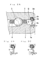
- [Fig. 2] (A) is a section view showing a sealing structure of a rolling bearing for a supercharger of a first embodiment of the invention. (B) and (C) show modifications of a sealing member (shield plate 5) used in the rolling bearing for a supercharger of the first embodiment.
- [Fig. 3] (A) is a section view showing a sealing structure of a rolling bearing for a supercharger of a second embodiment of the invention. (B) and (C) show modifications of a sealing member (seal 6) used in the rolling bearing for a supercharger of the second embodiment.
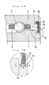
- [Fig. 4] (A) is a section view showing a sealing structure of a rolling bearing for a supercharger of a third embodiment of the invention. (B) is an enlarged view of a portion P in (A).
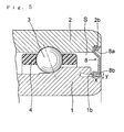
- [Fig. 5] Fig. 5 is a section view showing a sealing structure of a rolling bearing for a supercharger of a fourth embodiment of the invention.
- [Fig. 6] Fig. 6 is a section view showing a sealing structure in a conventional rolling bearing.
- [Fig. 7] Fig. 7 is a section view showing another sealing structure in the conventional rolling bearing.
-
- 1
- inner ring
- 1a, 1b, 1c, 1d
- sealing groove
- 2
- outer ring
- 2a, 2b, 2c, 2d
- locking groove
- 3
- ball
- 4
- cage
- 5
- shield plate (sealing member)
- 5a
- locking portion
- 5b
- rubber
- 5c
- end portion
- 6
- seal (sealing member)
- 6a
- locking portion
- 6b
- rubber
- 6c
- end portion
- 6d
- core metal
- 7
- seal (sealing member)
- 7a
- locking portion
- 7b
- rubber
- 7c
- end portion
- 8
- shield plate (sealing member)
- 8a
- locking portion
- 8b
- end portion
- 10
- shield plate (sealing member)
- 10a
- locking portion
- 10b
- end portion
- 11
- seal (sealing member)
- 11a
- locking portion
- 11b
- rubber
- 11c
- lip portion
- 11d
- core metal
- 21
- motor housing
- 22
- compressor housing
- 23
- shaft
- 24
- stator
- 25
- rotor
- 26
- compressor impeller
- B
- rolling bearing
- S
- bearing annular space
- Hereinafter, modes which execute the invention will be described with reference to the drawings.
Fig. 1 is a schematic section view showing the structure of a supercharger with an electric motor. Fig. 2 is an axial section view showing the structure of a rolling bearing for a supercharger of a first embodiment of the invention. - The supercharger with an electric motor in which rolling bearings B, B for a supercharger of the invention are used is an electric supercharger which is not provided with a turbine, and in which a compressor is driven only by an electric motor. A compressor portion provided with a
compressor impeller 26 and an electric motor portion are formed on both end sides of ashaft 23 of the electric supercharger. Compressed air is supplied to an engine by rotation of thecompressor impeller 26. Theshaft 23 is rotatably supported by the two rolling bearings B, B. Thereference numeral 21 in the figure denotes a motor housing, 22 denotes a compressor housing, 24 denotes a stator of the motor, and 25 denotes a rotor of the motor. - As shown in Fig. 2(A), the fundamental configuration of the rolling bearings B, B for a supercharger in the embodiment is similar to that of a conventional angular contact ball bearing, and is formed by: an
inner ring 1 having a raceway groove on an outer circumferential face; anouter ring 2 having a raceway groove on an inner circumferential face; a plurality ofballs 3 which are disposed in an annular space S formed between theinner ring 1 and theouter ring 2; and acage 4 for holding theballs 3 at predetermined intervals in a circumferential direction. In the annular space S, grease (not shown) is enclosed together with theballs 3 and thecage 4. As a material of theballs 3, ceramics is preferably used. - The rolling bearing for a supercharger of the embodiment is characterized in that a locking
portion 5a of a sealing member (shield plate 5) for sealing the annular space S is covered withrubber 5b. Theshield plate 5 is fixed in such a manner that the lockingportion 5a is fitted in a lockinggroove 2a formed in an end portion of theouter ring 2. - A gap (the distance: y = about 0.2 mm) is formed between an inner-ring
side end portion 5c of theshield plate 5 and a sealinggroove 1a of theinner ring 1. Theend portion 5c of theshield plate 5 is bent so as to be in parallel to the sealinggroove 1a. The axial length x of an opposed face of theshield plate 5 which is opposed to the sealinggroove 1a is 0.8 mm or more, when viewed in the axially parallel direction as shown in Fig. 2(A). - According to the above-described configuration, in the rolling bearing for a supercharger of the embodiment, the
rubber 5b is in close contact with the lockinggroove 2a, so that leakage of grease from the lockinggroove 2a caused by high-speed rotation of the supercharger can be prevented from occurring. In addition, since the length x of the opposed face of theshield plate 5 is set to be 0.8 mm or more, a labyrinth which is sufficient for preventing the leakage of grease is formed between theinner ring 1 and theshield plate 5. Accordingly, the rolling bearing for a supercharger of the embodiment can maintain good lubrication over a long period of time even in the use under high-speed rotation. - The shape of the
shield plate 5 is not restricted to the above-described embodiment. For example, as shown in Figs. 2(B) and 2(C), even when the locking portion and the end portion on the inner-ring side are changed, shapes which attain the same effects can be designed. - Next, a second embodiment of the invention will be described.
Fig. 3 is an axial section view showing the structure of a rolling bearing for a supercharger of a second embodiment of the invention. The configuration of a supercharger with an electric motor (Fig. 1) in which the rolling bearing for a supercharger is used is the same as that of the first embodiment, and hence the detailed description is omitted. - The rolling bearing for a supercharger of the embodiment is different from the first embodiment in that the sealing member is formed as a
seal 6 configured by acore metal 6a andrubber 6b. - The
seal 6 is fixed by fitting a lockingportion 6a covered with therubber 6b into the lockinggroove 2b of an end portion of theouter ring 2, similarly to theshield plate 5. A gap (the distance: y = about 0.2 mm) is formed between an inner-ringside end portion 6c of the seal and a sealinggroove 1b of theinner ring 1. As shown in Fig. 3(A), the axial length x of an opposed face of theseal 6 opposed to the sealinggroove 1b is 0.8 mm or more, when viewed in the axially parallel direction. - According to the above-described configuration, in the rolling bearing for a supercharger of the embodiment, leakage of grease from the locking
groove 2a caused by high-speed rotation of the supercharger can be prevented from occurring, and a labyrinth for preventing the leakage of grease from occurring is formed between theinner ring 1 and theseal 6. Accordingly, also the rolling bearing for a supercharger of the embodiment can maintain good lubrication over a long period of time. - Also the shape of the
seal 6 is not restricted to the above-described embodiment. For example, even when the thickness of the rubber portion is changed as shown in Fig. 3 (B) , or when a lip for extending the labyrinth is formed as shown in Fig. 3(C), shapes which attain the same effects can be designed. - The kinds of the rubber (5a, 5b) used in the rolling bearing for a supercharger of the invention are not particularly restricted, but acrylic rubber having a wider applicable temperature range, fluorine rubber, or the like is preferably used. Alternatively, nitrile rubber, silicon rubber, or the like may be used.
- Next, a third embodiment of the invention will be described.
Fig. 4 is an axial section view showing the structure of a rolling bearing for a supercharger of a third embodiment of the invention. Also the configuration of a supercharger with an electric motor (Fig. 1) in which the rolling bearing for a supercharger is used is the same as that of the first embodiment. - The rolling bearing for a supercharger of the embodiment is characterized in that the sealing
groove 1a of theinner ring 1 opposed to anend face 7c of aseal 7 is formed so as to have a tapered shape (conical shape) in which the diameter is increased as advancing from an axial end portion side toward a middle side. The inclination of the taperedsealing groove 1a is formed so that an angle θ with respect to the rotation axis of theinner ring 1 is 5 degrees or more, as shown in Fig. 4(B). - A gap (the distance y) is formed between the inner-ring
side end portion 7c of theseal 7 and the sealinggroove 1a of theinner ring 1. Theend portion 7c is formed so as to be in parallel to the sealinggroove 1a. As shown in Fig. 4(B), the axial length x of an opposed face of theseal 7 opposed to the sealinggroove 1a is twice or more as long as the distance y of the gap (x ≥ 2y), when it is viewed in the axially parallel direction. - According to the above-described configuration, in the rolling bearing for a supercharger of the embodiment, a labyrinth which is sufficient for preventing the leakage of grease from occurring is formed between the
inner ring 1 and theseal 7. Since the surface of the sealinggroove 1a is formed as an inclined face with an angle θ = 5 degrees or more, the grease which reaches the gap between theseal 7 and theinner ring 1 is pushed back to the middle side in the axial direction (to the inside of the bearing) by the centrifugal force of the rotation. Accordingly, the rolling bearing for a supercharger of the embodiment can maintain good lubrication for a long period of time also in the use under high-speed rotation. - Also the shape of the
seal 7 used in the invention is not restricted to the above-described embodiments, but various modifications can be formed. Alternatively, the sealing member may be ashield plate 8 as in a fourth embodiment (Fig. 5). The same effects as those in the above-described embodiments can be attained by theshield plate 8. - As described above, according to the invention of
claim 1, the rubber which covers the locking portion of the sealing member is in close contact with the locking groove of the outer ring, and the labyrinth which is sufficient for preventing the leakage of grease from occurring is formed. Therefore, the leakage of grease in the use under high-speed rotation can be prevented from occurring. - According to the invention of
claim 3, the force of pushing back the grease which reaches the gap between the sealing member and the inner ring toward the middle in the axial direction due to the centrifugal force is applied to the grease. Even in the case of high-speed rotation, therefore, the leakage of grease enclosed in the bearing to the outside can be suppressed. - Accordingly, the rolling bearing for a supercharger of the invention can be configured as a rolling bearing in which grease does not leak even in continuous operation under high-speed rotation, and which has a long life period.
Claims (6)
- A rolling bearing for a supercharger in which grease is enclosed in an annular space formed between an inner ring and an outer ring that are coaxially disposed, and a non-contact sealing member for forming a gap with said inner ring is disposed in a locking groove disposed in an end portion in an axial direction of said outer ring, wherein
at least a locking portion on a side of the outer ring of said sealing member is covered with rubber, and a length of an opposed face of an inner-ring side end portion of said sealing member which is opposed to said inner ring across said gap is 0.8 mm or more in a section view which is in parallel to an axis. - A rolling bearing for a supercharger according to claim 1, wherein a radial gap between said inner-ring side end face of said sealing member and said inner ring is 0.1 mm to 0.3 mm.
- A rolling bearing for a supercharger in which grease is enclosed in an annular space formed between an inner ring and an outer ring that are coaxially disposed, and a non-contact sealing member for forming a gap with said inner ring is disposed in a locking groove disposed in an end portion in an axial direction of said outer ring, wherein
an area of an outer circumferential face of said inner ring which is opposed to an inner-ring side end face of said sealing member is formed to have a tapered shape in which a diameter is more increased as advancing from an axial end portion side to a middle side. - A rolling bearing for a supercharger according to claim 3, wherein an angle formed by said tapered area and a rotation axis of said inner ring is 5 degrees or more.
- A rolling bearing for a supercharger according to claim 4, wherein said inner-ring side end face of said sealing member is formed to have a shape parallel to said tapered area.
- A rolling bearing for a supercharger according to claim 5, wherein an axial length of said inner-ring side end face of said sealing member is twice or more as long as a distance between said inner-ring side end face and said tapered area.
Applications Claiming Priority (3)
| Application Number | Priority Date | Filing Date | Title |
|---|---|---|---|
| JP2004040841A JP2005233249A (en) | 2004-02-18 | 2004-02-18 | Rolling bearing for supercharger |
| JP2004040839A JP2005233248A (en) | 2004-02-18 | 2004-02-18 | Roller bearing for supercharger |
| PCT/JP2005/002253 WO2005078298A1 (en) | 2004-02-18 | 2005-02-15 | Rolling bearing for supercharger |
Publications (2)
| Publication Number | Publication Date |
|---|---|
| EP1719927A1 true EP1719927A1 (en) | 2006-11-08 |
| EP1719927A4 EP1719927A4 (en) | 2007-09-26 |
Family
ID=34863484
Family Applications (1)
| Application Number | Title | Priority Date | Filing Date |
|---|---|---|---|
| EP05710204A Withdrawn EP1719927A4 (en) | 2004-02-18 | 2005-02-15 | Rolling bearing for supercharger |
Country Status (3)
| Country | Link |
|---|---|
| US (1) | US20070154124A1 (en) |
| EP (1) | EP1719927A4 (en) |
| WO (1) | WO2005078298A1 (en) |
Cited By (8)
| Publication number | Priority date | Publication date | Assignee | Title |
|---|---|---|---|---|
| DE102008061113A1 (en) * | 2008-12-09 | 2010-06-10 | Bosch Mahle Turbo Systems Gmbh & Co. Kg | Exhaust gas turbocharger for internal-combustion engine, particularly of motor vehicle, has shaft, which is mounted in housing of exhaust gas turbocharger by antifriction bearing in pivoted manner |
| FR2953576A1 (en) * | 2009-12-07 | 2011-06-10 | Skf Ab | Seal for use between rings of roller bearing for e.g. retention of grease, has flange including edge axially projecting relative to radial region and defining annular space together with ring, where space is filled with lubricant |
| EP2525108A1 (en) * | 2011-05-20 | 2012-11-21 | Aktiebolaget SKF | Turbocharger, notably for a combustion engine |
| CN105003548A (en) * | 2015-04-23 | 2015-10-28 | 江苏恒亮离心机制造有限公司 | Splitting-type thin oil lubricating bearing seat |
| EP2924261A4 (en) * | 2012-11-22 | 2016-07-20 | Mitsubishi Heavy Ind Ltd | POWER SUPPLY COMPRESSOR EQUIPPED WITH ELECTRIC MOTOR AND MOTORIZED DEVICE COMPRISING A POWER SUPPLY COMPRESSOR EQUIPPED WITH AN ELECTRIC MOTOR |
| CN106286844A (en) * | 2016-09-30 | 2017-01-04 | 大唐桂冠合山发电有限公司 | Rotate the bearing seal structure of machinery |
| GB2545427A (en) * | 2015-12-14 | 2017-06-21 | Valeo Air Man Uk Ltd | A bearing arrangement in an electric supercharger |
| WO2017220324A1 (en) * | 2016-06-20 | 2017-12-28 | Continental Automotive Gmbh | Electric compressor with compact bearing means |
Families Citing this family (23)
| Publication number | Priority date | Publication date | Assignee | Title |
|---|---|---|---|---|
| DE102006025580A1 (en) * | 2006-06-01 | 2007-12-06 | Schaeffler Kg | roller bearing |
| JP5120695B2 (en) * | 2007-11-08 | 2013-01-16 | 株式会社ジェイテクト | Rolling bearing device |
| DE102009021470A1 (en) * | 2009-05-15 | 2010-11-18 | Schaeffler Technologies Gmbh & Co. Kg | Sealing arrangement for a rolling bearing |
| DE102009053826A1 (en) * | 2009-11-18 | 2011-05-19 | Cw Bearing Gmbh | Cover disk i.e. metal cover disk, for sealing roller bearing against contamination and lubricant discharge, has elastomer molded at outer edge of disk, where disk is mounted by force-fitting in flat-sided groove at roller bearing outer ring |
| JP5529714B2 (en) | 2010-11-12 | 2014-06-25 | 三菱重工業株式会社 | Electric supercharger rotating shaft support structure |
| CN102242771B (en) * | 2011-04-18 | 2013-01-02 | 无锡市第二轴承有限公司 | High-speed sealed bearing |
| JP2012255457A (en) * | 2011-06-07 | 2012-12-27 | Nsk Ltd | Linear motion device |
| US9261178B2 (en) | 2011-06-07 | 2016-02-16 | Nsk Ltd. | Linear device |
| JP2013002687A (en) * | 2011-06-14 | 2013-01-07 | Sumitomo Heavy Ind Ltd | Cold storage refrigerator |
| CN104094004B (en) * | 2012-01-02 | 2018-02-09 | Skf公司 | A kind of large sealing self-aligning roller bearing |
| US8613556B2 (en) * | 2012-02-24 | 2013-12-24 | Ntn Usa Corporation | Bearing protection system |
| FR2992381B1 (en) * | 2012-06-26 | 2015-02-27 | Skf Ab | ROLLING BODY BEARING AND FLANGE |
| GB2529654A (en) * | 2014-08-28 | 2016-03-02 | Skf Ab | Bearing |
| WO2016123196A1 (en) * | 2015-01-28 | 2016-08-04 | Eaton Corporation | Low creep bearing and method for installing in supercharger |
| JP6582566B2 (en) | 2015-06-03 | 2019-10-02 | 株式会社ジェイテクト | Rolling bearing |
| JP6957836B2 (en) | 2016-01-26 | 2021-11-02 | 株式会社ジェイテクト | Rolling bearing |
| IT201600119828A1 (en) * | 2016-11-28 | 2018-05-28 | Skf Ab | VOLVENTIC BEARING WITH IMPROVED SEALING DEVICE |
| JP6874455B2 (en) | 2017-03-22 | 2021-05-19 | 株式会社ジェイテクト | Rolling bearing |
| JP6946697B2 (en) | 2017-03-31 | 2021-10-06 | 株式会社ジェイテクト | Rolling bearing |
| JP6950430B2 (en) | 2017-10-04 | 2021-10-13 | 株式会社ジェイテクト | Ball bearing |
| US11085330B2 (en) | 2018-02-19 | 2021-08-10 | Pratt & Whitney Canada Corp. | Seal and bearing assembly with bearing outer portion defining seal static portion |
| CN111365287B (en) * | 2018-12-25 | 2025-03-25 | 珠海格力电器股份有限公司 | Bearing support assembly and processing method thereof, centrifugal compressor |
| IT201900011646A1 (en) * | 2019-07-12 | 2021-01-12 | Skf Ab | THIN SECTION BEARING UNIT |
Family Cites Families (14)
| Publication number | Priority date | Publication date | Assignee | Title |
|---|---|---|---|---|
| US2114954A (en) * | 1936-01-10 | 1938-04-19 | S K F Ind Inc | Sealed bearing |
| JPS4740184Y1 (en) * | 1969-04-07 | 1972-12-05 | ||
| JPS57184222U (en) * | 1981-05-20 | 1982-11-22 | ||
| JPS5886925U (en) * | 1981-12-07 | 1983-06-13 | 光洋精工株式会社 | Sealing device for deep groove ball bearings |
| JPS5886924U (en) * | 1981-12-07 | 1983-06-13 | 光洋精工株式会社 | Sealing device for deep groove ball bearings |
| JPS58160627A (en) * | 1982-03-18 | 1983-09-24 | Nippon Seiko Kk | Lubricating device for rolling bearings |
| JPS59180016U (en) * | 1983-05-20 | 1984-12-01 | 日本精工株式会社 | Sealing device for rolling bearings |
| JPS60122026U (en) * | 1984-01-26 | 1985-08-17 | 日本精工株式会社 | Inner visible sealed bearing |
| JP3136687B2 (en) | 1991-09-12 | 2001-02-19 | 石川島播磨重工業株式会社 | Floating bush bearing |
| JP2917115B2 (en) * | 1995-11-20 | 1999-07-12 | ミネベア株式会社 | Rolling bearing |
| US6402158B1 (en) * | 1998-01-13 | 2002-06-11 | Nichia Precision Industry Co., Ltd. | Seal disk for bearings |
| JP2002266880A (en) * | 2001-03-05 | 2002-09-18 | Minebea Co Ltd | Seal structure of ball bearing |
| DE10113308A1 (en) * | 2001-03-20 | 2002-09-26 | Bosch Gmbh Robert | Electrically powered charge air compressor has compressor wheel movable between working and idle positions, and is at least partly removed from compression section in idle position |
| AU2003220844A1 (en) * | 2002-02-27 | 2003-09-09 | Nsk Ltd. | Rolling bearing |
-
2005
- 2005-02-15 EP EP05710204A patent/EP1719927A4/en not_active Withdrawn
- 2005-02-15 US US10/589,701 patent/US20070154124A1/en not_active Abandoned
- 2005-02-15 WO PCT/JP2005/002253 patent/WO2005078298A1/en not_active Ceased
Cited By (12)
| Publication number | Priority date | Publication date | Assignee | Title |
|---|---|---|---|---|
| DE102008061113A1 (en) * | 2008-12-09 | 2010-06-10 | Bosch Mahle Turbo Systems Gmbh & Co. Kg | Exhaust gas turbocharger for internal-combustion engine, particularly of motor vehicle, has shaft, which is mounted in housing of exhaust gas turbocharger by antifriction bearing in pivoted manner |
| FR2953576A1 (en) * | 2009-12-07 | 2011-06-10 | Skf Ab | Seal for use between rings of roller bearing for e.g. retention of grease, has flange including edge axially projecting relative to radial region and defining annular space together with ring, where space is filled with lubricant |
| EP2525108A1 (en) * | 2011-05-20 | 2012-11-21 | Aktiebolaget SKF | Turbocharger, notably for a combustion engine |
| EP2924261A4 (en) * | 2012-11-22 | 2016-07-20 | Mitsubishi Heavy Ind Ltd | POWER SUPPLY COMPRESSOR EQUIPPED WITH ELECTRIC MOTOR AND MOTORIZED DEVICE COMPRISING A POWER SUPPLY COMPRESSOR EQUIPPED WITH AN ELECTRIC MOTOR |
| US10072667B2 (en) | 2012-11-22 | 2018-09-11 | Mitsubishi Heavy Industries Engine & Turbocharger, Ltd. | Supercharger with electric motor and engine device provided with supercharger with electric motor |
| CN105003548A (en) * | 2015-04-23 | 2015-10-28 | 江苏恒亮离心机制造有限公司 | Splitting-type thin oil lubricating bearing seat |
| GB2545427A (en) * | 2015-12-14 | 2017-06-21 | Valeo Air Man Uk Ltd | A bearing arrangement in an electric supercharger |
| WO2017102377A1 (en) * | 2015-12-14 | 2017-06-22 | Valeo Air Management Uk Limited | A bearing arrangement in an electric supercharger |
| GB2545427B (en) * | 2015-12-14 | 2020-12-23 | Valeo Air Man Uk Limited | A bearing arrangement in an electric supercharger |
| WO2017220324A1 (en) * | 2016-06-20 | 2017-12-28 | Continental Automotive Gmbh | Electric compressor with compact bearing means |
| CN106286844A (en) * | 2016-09-30 | 2017-01-04 | 大唐桂冠合山发电有限公司 | Rotate the bearing seal structure of machinery |
| CN106286844B (en) * | 2016-09-30 | 2019-04-05 | 大唐桂冠合山发电有限公司 | Rotate mechanical bearing seal structure |
Also Published As
| Publication number | Publication date |
|---|---|
| US20070154124A1 (en) | 2007-07-05 |
| WO2005078298A1 (en) | 2005-08-25 |
| EP1719927A4 (en) | 2007-09-26 |
Similar Documents
| Publication | Publication Date | Title |
|---|---|---|
| US20070154124A1 (en) | Rolling bearing for a supercharger | |
| US7517154B2 (en) | Turbocharger shaft bearing system | |
| US20070280824A1 (en) | Combination hydrodynamic and rolling bearing system | |
| EP2279352B1 (en) | Bearing device for supercharger | |
| US7334799B2 (en) | Sealing device for a turbocharger | |
| US7048445B2 (en) | Cylindrical roller bearing | |
| JP2001012610A (en) | Face seal structure | |
| CN102748390A (en) | Hydrodynamic axial bearing | |
| JP4367628B2 (en) | Electric motor integrated turbocharger | |
| CN102159860A (en) | Device for sealing off a bearing housing of an exhaust-gas turbocharger | |
| JP2002369474A (en) | Rolling bearing device for impeller shaft support | |
| JP6704107B2 (en) | Thrust collar and thrust bearing device | |
| CN112628188B (en) | High negative pressure resistant turbocharger compressor end sealing structure | |
| US11078807B2 (en) | Turbocharger and mating ring included therein | |
| US7547185B2 (en) | Output shaft air/oil separator to redundantly protect against output shaft o-ring leakage | |
| JP2010138753A (en) | Bearing device for supercharger | |
| JP2001280347A (en) | Ball bearing | |
| JP2005233248A (en) | Roller bearing for supercharger | |
| JP2009203846A (en) | Ball bearing arrangement for turbocharger | |
| US11788580B2 (en) | Rolling bearing | |
| JP2005233249A (en) | Rolling bearing for supercharger | |
| JP2013002429A (en) | Lubricating oil seal structure on turbine side of supercharger | |
| JP2004270774A (en) | Pulley with bearing | |
| JP2003287031A (en) | Ball bearing | |
| JP2002106569A (en) | Rotary support device for turbocharger |
Legal Events
| Date | Code | Title | Description |
|---|---|---|---|
| PUAI | Public reference made under article 153(3) epc to a published international application that has entered the european phase |
Free format text: ORIGINAL CODE: 0009012 |
|
| 17P | Request for examination filed |
Effective date: 20060915 |
|
| AK | Designated contracting states |
Kind code of ref document: A1 Designated state(s): DE FR GB IT |
|
| DAX | Request for extension of the european patent (deleted) | ||
| RBV | Designated contracting states (corrected) |
Designated state(s): DE FR GB IT |
|
| RIC1 | Information provided on ipc code assigned before grant |
Ipc: F16J 15/44 20060101ALI20070430BHEP Ipc: F16C 33/80 20060101AFI20050903BHEP |
|
| A4 | Supplementary search report drawn up and despatched |
Effective date: 20070829 |
|
| 17Q | First examination report despatched |
Effective date: 20080813 |
|
| STAA | Information on the status of an ep patent application or granted ep patent |
Free format text: STATUS: THE APPLICATION IS DEEMED TO BE WITHDRAWN |
|
| 18D | Application deemed to be withdrawn |
Effective date: 20091110 |