EP1719441B1 - Soap dispensing apparatus - Google Patents
Soap dispensing apparatus Download PDFInfo
- Publication number
- EP1719441B1 EP1719441B1 EP05076055A EP05076055A EP1719441B1 EP 1719441 B1 EP1719441 B1 EP 1719441B1 EP 05076055 A EP05076055 A EP 05076055A EP 05076055 A EP05076055 A EP 05076055A EP 1719441 B1 EP1719441 B1 EP 1719441B1
- Authority
- EP
- European Patent Office
- Prior art keywords
- cover
- base part
- container
- dispensing apparatus
- hinge point
- Prior art date
- Legal status (The legal status is an assumption and is not a legal conclusion. Google has not performed a legal analysis and makes no representation as to the accuracy of the status listed.)
- Active
Links
Images


Classifications
-
- A—HUMAN NECESSITIES
- A47—FURNITURE; DOMESTIC ARTICLES OR APPLIANCES; COFFEE MILLS; SPICE MILLS; SUCTION CLEANERS IN GENERAL
- A47K—SANITARY EQUIPMENT NOT OTHERWISE PROVIDED FOR; TOILET ACCESSORIES
- A47K5/00—Holders or dispensers for soap, toothpaste, or the like
- A47K5/06—Dispensers for soap
- A47K5/12—Dispensers for soap for liquid or pasty soap
- A47K5/1202—Dispensers for soap for liquid or pasty soap dispensing dosed volume
- A47K5/1204—Dispensers for soap for liquid or pasty soap dispensing dosed volume by means of a rigid dispensing chamber and pistons
- A47K5/1205—Dispensing from the top of the dispenser with a vertical piston
-
- A—HUMAN NECESSITIES
- A47—FURNITURE; DOMESTIC ARTICLES OR APPLIANCES; COFFEE MILLS; SPICE MILLS; SUCTION CLEANERS IN GENERAL
- A47K—SANITARY EQUIPMENT NOT OTHERWISE PROVIDED FOR; TOILET ACCESSORIES
- A47K5/00—Holders or dispensers for soap, toothpaste, or the like
- A47K5/06—Dispensers for soap
- A47K5/12—Dispensers for soap for liquid or pasty soap
- A47K5/1202—Dispensers for soap for liquid or pasty soap dispensing dosed volume
- A47K5/1208—Dispensers for soap for liquid or pasty soap dispensing dosed volume by means of a flexible dispensing chamber
-
- A—HUMAN NECESSITIES
- A47—FURNITURE; DOMESTIC ARTICLES OR APPLIANCES; COFFEE MILLS; SPICE MILLS; SUCTION CLEANERS IN GENERAL
- A47K—SANITARY EQUIPMENT NOT OTHERWISE PROVIDED FOR; TOILET ACCESSORIES
- A47K5/00—Holders or dispensers for soap, toothpaste, or the like
- A47K5/06—Dispensers for soap
- A47K5/12—Dispensers for soap for liquid or pasty soap
- A47K5/1202—Dispensers for soap for liquid or pasty soap dispensing dosed volume
- A47K5/1204—Dispensers for soap for liquid or pasty soap dispensing dosed volume by means of a rigid dispensing chamber and pistons
- A47K5/1207—Dispensing from the bottom of the dispenser with a vertical piston
-
- A—HUMAN NECESSITIES
- A47—FURNITURE; DOMESTIC ARTICLES OR APPLIANCES; COFFEE MILLS; SPICE MILLS; SUCTION CLEANERS IN GENERAL
- A47K—SANITARY EQUIPMENT NOT OTHERWISE PROVIDED FOR; TOILET ACCESSORIES
- A47K5/00—Holders or dispensers for soap, toothpaste, or the like
- A47K5/14—Foam or lather making devices
Definitions
- the invention relates to a dispensing apparatus for dispensing a product from a container according to the preamble of claim 1. Moreover, the invention relates to an assembly of a dispensing apparatus and a product container according to claim 11.
- the invention relates particularly to an apparatus for dispensing certain quantities of liquid or foamed soap, which is contained in disposable or reusable containers which can be replaced when the container is empty.
- the front cover In order to change the container the front cover should be opened and hinged from the base plate. This operation may only be performed by certain people, whereas it should be impossible or at least not easy for users of the dispensing apparatus to open the cover.
- the dispenser should be used and operated by a wide range of users.
- the cover is entirely used as an operating button. By pushing on the cover, product will be dispensed.
- For replacing the container it must be possible to pivot the cover to a container-loading position while it keeps connected to the base part.
- the cover must be pivoted about a hinge point with respect to the base plate in order to dispense the product.
- the cover can be opened for replacing the container when the hinge point between the cover and the base plate is released.
- a dispensing apparatus is known from EP-A-1454576 .
- movement of the cover to a container-loading position is prevented unless the cover is detached from its hinge point with the base part.
- the hinge point is arranged between the cover and the base part and comprises lateral sockets in the base part cooperating with spigots at the inner side of the cover.
- the hinge assembly is locked by resilient retention members which retain the spigots in their sockets. Locking levers extend from an opening in the cover provided on the base part. Upon depression of the levers the retention members are lowered and the spigots can be removed from the sockets. The cover can be rotated to its container-loading position.
- the present invention is intended to provide an improved dispensing apparatus which is easy to operate, while containers can be exchanged easily but not unintended and malfunctions are prevented.
- the dispensing apparatus is characterized in that the second hinge point is arranged between the cover and the mounting element, which is locked in the base part. Upon unlocking the mounting element, the mounting element with cover can be moved relative to the base part for releasing the first hinge point.
- the locking of the mounting element is realised in that the mounting element comprises at least an extended portion cooperating with an opening in the base part.
- the base part comprises at least a retention rib cooperating with the extended portion of the mounting element for preventing the cover from separating from the base part. An unintended removal of the cover from the base part is herewith prevented.
- the first hinge point is arranged between the cover and the base part and releasable by relative movement between those two. After the mounting element is unlocked from the base part, the cover can be moved relative to the base part in a direction of releasing the first hinge point.
- cooperating blocking means between the cover and the base part for blocking relative movement between those two are preferably provided.
- the mounting element should be unlocked from the base part and the blocking means between the cover and the base part should be brought into their non-cooperating position in order to move the cover with respect to the base part and release the first hinge point.
- the dispensing apparatus comprises also resilient means for returning the cover about the first hinge point to a non-dispensing position after releasing the cover wherein the resilient means are integrally connected to the mounting element.
- the resilient means comprise at least a flexible arm of the mounting element.
- the mounting element can preferably be produced from plastic. Flexibility of the arm is obtained by having proper dimensions and material.
- a first part of the second hinge point is integrally connected to the flexible arm of the mounting element and a second part of the second hinge point is connected to the cover.
- the first part comprises a pivot hole in the flexible arm and the second part comprises a pivoting pin integrally connected to the cover.
- the container is replaceable when it is empty, although it is also possible to have a fixed container which can be refilled.
- the expression cartridge is used herein.
- the cartridge comprises a container of the product and a pump connected thereto, although it is also possible to have a separate pump arranged in the dispensing apparatus which is not replaced when the cartridge is empty.
- pumps possible for use with the container of product, such as a bellows pump, a foam pump, a hose pump or a container having a flexible wall which can be depressed by some kind of pushing element.
- an actuating element is provided which is pivotally connected to the mounting element for actuating the bellows pump.
- the pivoting movement of the cover with respect to the base part for dispensing product is translated into an actuation movement of the bellows pump by this actuating element.
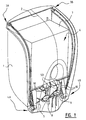
- FIG. 1 gives a perspective view of a first embodiment of the dispensing apparatus according to the invention.
- the dispensing apparatus comprises a base part 1, a cover 2 connected to the base part 1 by means of two hinge points 3a,3b resp. 4a,4b and a mounting element 5 for mounting a cartridge 6 of product between the cover 2 and the base part 1.
- the cartridge 6 of this first embodiment comprises a container 7 filled with product and a bellows pump 8 connected thereto.
- an actuating element 9 is arranged on the mounting element 5 and in contact with the cover 2 for actuating the bellows pump 8 of the cartridge 6.
- the mounting element 5 of figure 1 is clearly shown in Figure 2 .
- the mounting element 5 is shown from the back, i.e. the side which is directed to the base part 1 of the dispensing apparatus of Figure 1 .
- the mounting element 5 is a one-piece structural component, preferably produced from plastic, which accommodates several functions for the dispensing apparatus, as will be explained later on.
- the mounting element 5 comprises an upper wall 20 with a recessed part 21 in the centre thereof. This recessed part 21 is more clearly shown in Figure 5 . This recessed part 21 is provided at the front of the mounting element 5 with a substantially U-shaped recess 22. Furthermore, a rib 23 is provided in the recessed upper wall 21.
- Two flexible arms 24 extend from the upper wall. Pivot holes 25 and extended portions 26 are integrally connected to these flexible arms 24. Furthermore, the mounting element 5 is provided with two upright walls 27 projecting from the upper wall 20 at right angles. In these upright walls 27, slotted holes 28 are provided.
- the base part 1 is clearly shown in Figure 3 .
- the base part 1 consists mainly of a back plate 30 with a curved lower end and two side walls 31, 32.
- the back plate 30 is provided with several slotted holes 33 of different dimensions for mounting the base part 1 to a wall of a sanitary room or space where the dispensing apparatus is to be used.
- Two openings 34 are arranged in the curved lower end of the back plate 30. These openings 34 are limited by retention ribs 35.
- the front edge 36 of the back plate 30 comprises a recessed part 37.
- connecting elements 38, 39 are integrally connected to the back plate 30 for cooperating with corresponding portions of the mounting element 5 to connect this element to the base part 1.
- the side walls 31,32 of the base part 1 have front edges in which slotted holes 40 at the upper end of the dispensing apparatus and interruptions 41 near the lower end of the dispensing apparatus are provided.
- the base part 1 has on its inner side positioning elements 42 for positioning a cartridge in its proper location.
- Figure 5 shows how the mounting element 5 of Figure 2 is mounted to the base part 1 of Figure 3 .
- the extended portions 26 of the mounting element 5 are positioned in the openings 34 of the lower curved end of the base part 1 (see also Figure 11 ).
- the connecting elements 38,39 on the back plate 30 connect the mounting element 5 to the base part 1.
- the flexible arms 24 project forward with the pivot holes 25 at the lower end of the back part 1.
- the actuating element 9 is more clearly shown in Figure 4 .
- This element comprises two parallel walls 50 mutually connected by a rib 51.
- Each wall 50 is connected to a flange 52, which has a curved end 53 at the front of the actuating element 9 (right side in Figure 4 ).
- These curved ends 53 cooperate with ribs 10 on the inner side of cover 2 (see Figure 1 ).
- pivoting pins 54 are provided at the back side of the actuating element 9, whereas a slotted opening 55 is provided at the front thereof.
- the pivoting pins 54 cooperate with the slotted holes 28 of the mounting element 5 (see Figure 2 ). In this way, the actuating element 9 is pivotally connected to the mounting element 5.
- FIG 7 shows how the actuating element 9 of Figure 4 is mounted to the assembly of Figure 5 .
- the actuating element 9 can rotate freely about a hinge point consisting of the pivoting pins 54 of the actuating element 9 and the slotted holes 28 of the mounting element 5. This hinge point is not shown in Figure 7 , because it lies at the back side (i.e. between the element 5,9 and the back plate 30).
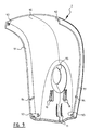
- FIG. 6 shows one example of a cartridge 6 for loading in the dispensing apparatus according to the invention.
- This cartridge 6 comprises a container 7 filled with product and a bellows pump 8.
- the bellows pump 8 is provided with a nozzle 60 through which the product will leave the cartridge 6.
- the bellows pump 8 is provided with retention rings 61,62. Between these retention rings 61,62 the bellows part 63 of the pump is located.
- FIG 8 the assembly of cartridge 6 and assembly according to Figure 7 are depicted.
- the container 7 is supported by the upper wall 20 of the mounting element 5. Thereby, the container 7 rest against the positioning elements 42 on the back plate 30 of the base part 1.
- the bellows pump 8 is retained by means of its retaining rings 61,62 in the U-shaped recess 22 of the mounting element 5 and the slotted opening 55 of the actuating element 9.
- the nozzle 60 of the bellows pump 8 extends downwardly.
- the cover 2 is more clearly shown in Figure 9 .
- the cover has a front wall 90 and two side flanges 91. At the upper end of the cover 2 there are provided two pivoting pins 92. Two further pivoting pins 93 are provided at the lower end of the cover 2.
- the side flanges 91 are provided with ribs 94 near the lower end of the cover 2.
- the pivoting pins 92,93 and ribs 94 are all integrally connected to the side flanges 92 of the cover 2.
- a recessed portion 95 of the front wall 90 is meant to be touched by a user when product has to be dispensed.
- Ribs 10 at the inner side of front wall 90 cooperate with the curved ends 53 of the actuating element 9 for actuating the bellows pump.
- Ribs 11 have a similar function when a cartridge comprising a foam pump is loaded in the dispensing apparatus (see Figure 10 ).
- the flexible arms 24 provide for returning the cover 2 to its rest position when it is released
- Figure 1 shows the complete assembly, including the cover 2 of Figure 9 .
- the pivoting pins 92 of the cover 2 and the slotted holes 40 of the base part 1 cooperate to form the first hinge point 3a,3b of the cover 2.
- the pivoting pins 93 of the cover 2 and the pivot holes 25 of the mounting element 5 cooperate to form the second hinge point 4a,4b of the cover 2.
- the second hinge point 4a,4b is not operative in the position shown in Figure 1 . It is only operative when the first hinge point 3a,3b is released, i.e. the pivoting pins 92 are lifted from the slotted holes 40. Releasing of the first hinge point 3a,3b is locked due to the connection between the extended portions 26 of the mounting element 5 and the openings 34 of the base part 1.
- Figure 10 shows a second embodiment of the dispensing apparatus according to the invention.
- This embodiment is suited for a cartridge comprising a container 7 filled with product and a foam pump 100.
- the base part 1, the cover 2 and the mounting element 101 are substantially identical to those of the first embodiment.
- the mounting element 101 comprises fixing lips 102 extending from the upper wall 20 in a forward downward direction for fixing the foam pump 100.
- the actuating element 9 of the first embodiment is not needed in this second embodiment. Pivoting movement of the cover about first hinge point 3a,3b directly results in an actuating movement of the foam pump and thus a dispensing of product.
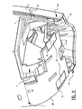
- Figure 11 shows a detail of the lower end of the dispensing apparatus of the first embodiment.
- the mounting element 5 is locked in the base part 1 by means of the extended portions 26 cooperating with the openings 34. From this situation it is not possible to lift the cover with respect to the base part because this relative movement is prevented by the ribs 94 cooperating with the interruptions 41.
- the extended portions 26 For bringing the cover 2 in a cartridge-loading position, the extended portions 26 have to be pushed inward. The extended portions 26 will release from the back plate 30 and the mounting element 5 can be pulled forward (right side in Figure 11 ). This movement in forward direction is limited by ribs 35 on the curved lower end of the back plate 30 in order to prevent a complete removal of the cover 2 from the base part 1.
- a dispensing apparatus having a maximum of four structural elements: a base part, a cover, a mounting element and an actuating element (only in case of a bellow pump type of cartridge).
- the mounting element combines the functions of mounting the cartridge in the dispensing apparatus, returning the cover after dispensing of product, providing a hinge point for opening the cover in order to unload and load a cartridge and locking the movement of the cover to its cartridge-loading position.
Abstract
Description
- The invention relates to a dispensing apparatus for dispensing a product from a container according to the preamble of
claim 1. Moreover, the invention relates to an assembly of a dispensing apparatus and a product container according toclaim 11. - The invention relates particularly to an apparatus for dispensing certain quantities of liquid or foamed soap, which is contained in disposable or reusable containers which can be replaced when the container is empty. In order to change the container the front cover should be opened and hinged from the base plate. This operation may only be performed by certain people, whereas it should be impossible or at least not easy for users of the dispensing apparatus to open the cover.
- Furthermore, it is important to dispense product in a clean and easy manner. The dispenser should be used and operated by a wide range of users. The cover is entirely used as an operating button. By pushing on the cover, product will be dispensed. For replacing the container it must be possible to pivot the cover to a container-loading position while it keeps connected to the base part. The cover must be pivoted about a hinge point with respect to the base plate in order to dispense the product. The cover can be opened for replacing the container when the hinge point between the cover and the base plate is released.
- A dispensing apparatus according to the preamble of
claim 1 is known fromEP-A-1454576 . In this dispensing apparatus movement of the cover to a container-loading position is prevented unless the cover is detached from its hinge point with the base part. The hinge point is arranged between the cover and the base part and comprises lateral sockets in the base part cooperating with spigots at the inner side of the cover. The hinge assembly is locked by resilient retention members which retain the spigots in their sockets. Locking levers extend from an opening in the cover provided on the base part. Upon depression of the levers the retention members are lowered and the spigots can be removed from the sockets. The cover can be rotated to its container-loading position. - The present invention is intended to provide an improved dispensing apparatus which is easy to operate, while containers can be exchanged easily but not unintended and malfunctions are prevented.
- Therefore, according to the present invention the dispensing apparatus is characterized in that the second hinge point is arranged between the cover and the mounting element, which is locked in the base part. Upon unlocking the mounting element, the mounting element with cover can be moved relative to the base part for releasing the first hinge point.
- In a preferred embodiment the locking of the mounting element is realised in that the mounting element comprises at least an extended portion cooperating with an opening in the base part.
- Preferably, the base part comprises at least a retention rib cooperating with the extended portion of the mounting element for preventing the cover from separating from the base part. An unintended removal of the cover from the base part is herewith prevented.
- In a preferred embodiment the first hinge point is arranged between the cover and the base part and releasable by relative movement between those two. After the mounting element is unlocked from the base part, the cover can be moved relative to the base part in a direction of releasing the first hinge point.
- Additionally, cooperating blocking means between the cover and the base part for blocking relative movement between those two are preferably provided. In this embodiment, the mounting element should be unlocked from the base part and the blocking means between the cover and the base part should be brought into their non-cooperating position in order to move the cover with respect to the base part and release the first hinge point.
- In a further embodiment the dispensing apparatus comprises also resilient means for returning the cover about the first hinge point to a non-dispensing position after releasing the cover wherein the resilient means are integrally connected to the mounting element.
- In a preferred embodiment the resilient means comprise at least a flexible arm of the mounting element. The mounting element can preferably be produced from plastic. Flexibility of the arm is obtained by having proper dimensions and material.
- In a further preferred embodiment a first part of the second hinge point is integrally connected to the flexible arm of the mounting element and a second part of the second hinge point is connected to the cover.
- In another preferred embodiment the first part comprises a pivot hole in the flexible arm and the second part comprises a pivoting pin integrally connected to the cover.
- In a preferred embodiment the container is replaceable when it is empty, although it is also possible to have a fixed container which can be refilled. When the container is replaceable the expression cartridge is used herein. Preferably, the cartridge comprises a container of the product and a pump connected thereto, although it is also possible to have a separate pump arranged in the dispensing apparatus which is not replaced when the cartridge is empty. There are several different types of pumps possible for use with the container of product, such as a bellows pump, a foam pump, a hose pump or a container having a flexible wall which can be depressed by some kind of pushing element.
- According to the invention when the dispensing apparatus is suited for a container with a bellows pump, an actuating element is provided which is pivotally connected to the mounting element for actuating the bellows pump. The pivoting movement of the cover with respect to the base part for dispensing product is translated into an actuation movement of the bellows pump by this actuating element.
- According to the present invention there is also provided an assembly of the dispensing apparatus and a product container as claimed in claims 11-13.
- The invention will be described by way of example and with reference to the accompanying drawings, in which:
-
Figure 1 shows a perspective view of a first embodiment of a dispensing apparatus according the invention; -
Figure 2 shows a perspective view of a mounting element; -
Figure 3 shows a perspective view of a base part; -
Figure 4 shows a perspective view of an actuating element; -
Figure 5 shows a perspective view of the mounting element ofFigure 2 arranged in the base part ofFigure 3 ; -
Figure 6 shows a cartridge comprising a container and a bellows pump; -
Figure 7 shows the actuating element ofFigure 4 arranged in the assembly ofFigure 5 ; -
Figure 8 shows the cartridge ofFigure 6 arranged in the assembly ofFigure 7 ; -
Figure 9 shows a perspective view of a cover; -
Figure 10 shows a perspective view of a second embodiment of a dispensing apparatus according to the invention, and -
Figure 11 shows a partly cut away view of the bottom side of the dispensing apparatus ofFigure 1 . -
Figure 1 gives a perspective view of a first embodiment of the dispensing apparatus according to the invention. The dispensing apparatus comprises abase part 1, acover 2 connected to thebase part 1 by means of two hinge points 3a,3b resp. 4a,4b and amounting element 5 for mounting acartridge 6 of product between thecover 2 and thebase part 1. Thecartridge 6 of this first embodiment comprises acontainer 7 filled with product and abellows pump 8 connected thereto. Furthermore, an actuatingelement 9 is arranged on themounting element 5 and in contact with thecover 2 for actuating thebellows pump 8 of thecartridge 6. - The
mounting element 5 offigure 1 is clearly shown inFigure 2 . Themounting element 5 is shown from the back, i.e. the side which is directed to thebase part 1 of the dispensing apparatus ofFigure 1 . Themounting element 5 is a one-piece structural component, preferably produced from plastic, which accommodates several functions for the dispensing apparatus, as will be explained later on. - The
mounting element 5 comprises anupper wall 20 with arecessed part 21 in the centre thereof. Thisrecessed part 21 is more clearly shown inFigure 5 . Thisrecessed part 21 is provided at the front of themounting element 5 with a substantiallyU-shaped recess 22. Furthermore, arib 23 is provided in the recessedupper wall 21. - Two
flexible arms 24 extend from the upper wall. Pivot holes 25 andextended portions 26 are integrally connected to theseflexible arms 24. Furthermore, the mountingelement 5 is provided with twoupright walls 27 projecting from theupper wall 20 at right angles. In theseupright walls 27, slottedholes 28 are provided. - The
base part 1 is clearly shown inFigure 3 . Thebase part 1 consists mainly of aback plate 30 with a curved lower end and twoside walls back plate 30 is provided with several slottedholes 33 of different dimensions for mounting thebase part 1 to a wall of a sanitary room or space where the dispensing apparatus is to be used. Twoopenings 34 are arranged in the curved lower end of theback plate 30. Theseopenings 34 are limited byretention ribs 35. Thefront edge 36 of theback plate 30 comprises a recessedpart 37. Furthermore, connectingelements back plate 30 for cooperating with corresponding portions of the mountingelement 5 to connect this element to thebase part 1. Theside walls base part 1 have front edges in which slottedholes 40 at the upper end of the dispensing apparatus andinterruptions 41 near the lower end of the dispensing apparatus are provided. Finally, thebase part 1 has on its innerside positioning elements 42 for positioning a cartridge in its proper location. -
Figure 5 shows how the mountingelement 5 ofFigure 2 is mounted to thebase part 1 ofFigure 3 . Theextended portions 26 of the mountingelement 5 are positioned in theopenings 34 of the lower curved end of the base part 1 (see alsoFigure 11 ). The connectingelements back plate 30 connect the mountingelement 5 to thebase part 1. Theflexible arms 24 project forward with the pivot holes 25 at the lower end of theback part 1. - The
actuating element 9 is more clearly shown inFigure 4 . This element comprises twoparallel walls 50 mutually connected by arib 51. Eachwall 50 is connected to aflange 52, which has acurved end 53 at the front of the actuating element 9 (right side inFigure 4 ). These curved ends 53 cooperate withribs 10 on the inner side of cover 2 (seeFigure 1 ). Furthermore, pivoting pins 54 are provided at the back side of theactuating element 9, whereas a slottedopening 55 is provided at the front thereof. The pivoting pins 54 cooperate with the slottedholes 28 of the mounting element 5 (seeFigure 2 ). In this way, theactuating element 9 is pivotally connected to the mountingelement 5. -
Figure 7 shows how theactuating element 9 ofFigure 4 is mounted to the assembly ofFigure 5 . Theactuating element 9 can rotate freely about a hinge point consisting of the pivoting pins 54 of theactuating element 9 and the slottedholes 28 of the mountingelement 5. This hinge point is not shown inFigure 7 , because it lies at the back side (i.e. between theelement -
Figure 6 shows one example of acartridge 6 for loading in the dispensing apparatus according to the invention. Thiscartridge 6 comprises acontainer 7 filled with product and abellows pump 8. When the bellows pump 8 is pushed toward thecontainer 7, a quantity of product will be dispensed. The bellows pump 8 is provided with anozzle 60 through which the product will leave thecartridge 6. Furthermore, the bellows pump 8 is provided with retention rings 61,62. Between these retention rings 61,62 thebellows part 63 of the pump is located. - In
Figure 8 , the assembly ofcartridge 6 and assembly according toFigure 7 are depicted. Thecontainer 7 is supported by theupper wall 20 of the mountingelement 5. Thereby, thecontainer 7 rest against thepositioning elements 42 on theback plate 30 of thebase part 1. The bellows pump 8 is retained by means of its retaining rings 61,62 in theU-shaped recess 22 of the mountingelement 5 and the slotted opening 55 of theactuating element 9. Thenozzle 60 of the bellows pump 8 extends downwardly. - The
cover 2 is more clearly shown inFigure 9 . The cover has afront wall 90 and twoside flanges 91. At the upper end of thecover 2 there are provided two pivoting pins 92. Two further pivotingpins 93 are provided at the lower end of thecover 2. The side flanges 91 are provided withribs 94 near the lower end of thecover 2. The pivoting pins 92,93 andribs 94 are all integrally connected to theside flanges 92 of thecover 2. A recessedportion 95 of thefront wall 90 is meant to be touched by a user when product has to be dispensed.Ribs 10 at the inner side offront wall 90 cooperate with the curved ends 53 of theactuating element 9 for actuating the bellows pump.Ribs 11 have a similar function when a cartridge comprising a foam pump is loaded in the dispensing apparatus (seeFigure 10 ). Theflexible arms 24 provide for returning thecover 2 to its rest position when it is released. -
Figure 1 shows the complete assembly, including thecover 2 ofFigure 9 . The pivoting pins 92 of thecover 2 and the slottedholes 40 of thebase part 1 cooperate to form the first hinge point 3a,3b of thecover 2. The pivoting pins 93 of thecover 2 and the pivot holes 25 of the mountingelement 5 cooperate to form the second hinge point 4a,4b of thecover 2. The second hinge point 4a,4b is not operative in the position shown inFigure 1 . It is only operative when the first hinge point 3a,3b is released, i.e. the pivoting pins 92 are lifted from the slotted holes 40. Releasing of the first hinge point 3a,3b is locked due to the connection between theextended portions 26 of the mountingelement 5 and theopenings 34 of thebase part 1. -
Figure 10 shows a second embodiment of the dispensing apparatus according to the invention. This embodiment is suited for a cartridge comprising acontainer 7 filled with product and a foam pump 100. Thebase part 1, thecover 2 and the mounting element 101 are substantially identical to those of the first embodiment. The mounting element 101, however, comprises fixing lips 102 extending from theupper wall 20 in a forward downward direction for fixing the foam pump 100. Another difference is that theactuating element 9 of the first embodiment is not needed in this second embodiment. Pivoting movement of the cover about first hinge point 3a,3b directly results in an actuating movement of the foam pump and thus a dispensing of product. -
Figure 11 shows a detail of the lower end of the dispensing apparatus of the first embodiment. The mountingelement 5 is locked in thebase part 1 by means of theextended portions 26 cooperating with theopenings 34. From this situation it is not possible to lift the cover with respect to the base part because this relative movement is prevented by theribs 94 cooperating with theinterruptions 41. For bringing thecover 2 in a cartridge-loading position, theextended portions 26 have to be pushed inward. Theextended portions 26 will release from theback plate 30 and the mountingelement 5 can be pulled forward (right side inFigure 11 ). This movement in forward direction is limited byribs 35 on the curved lower end of theback plate 30 in order to prevent a complete removal of thecover 2 from thebase part 1. As soon as thecover 2 is pulled forward, theribs 94 will release from theinterruptions 41. At that moment it is possible to lift the cover and release the first hinge point 3a,3b so that thecover 2 can be rotated about the second hinge point 4a,4b to the cartridge-loading position. - According to the invention a dispensing apparatus is provided having a maximum of four structural elements: a base part, a cover, a mounting element and an actuating element (only in case of a bellow pump type of cartridge). The mounting element combines the functions of mounting the cartridge in the dispensing apparatus, returning the cover after dispensing of product, providing a hinge point for opening the cover in order to unload and load a cartridge and locking the movement of the cover to its cartridge-loading position.
Claims (15)
- Dispensing apparatus for dispensing a product from a container, comprising:- a base part (1);- a cover (2) connected to the base part (1) by means of two hinge points (3a, 3b; 4a, 4b), a first releasable hinge point (3a, 3b) being provided for pivoting the cover (2) with respect to the base part (1) for dispensing product, a second hinge point (4a,4b) being provided for moving the cover (1) into a container-loading position, wherein the second hinge point (4a,4b) is operative if the first hinge point (3a, 3b) is released, and- a mounting element (5) for mounting the container (7) of product between the cover (2) and the base part (1), characterized in that the second hinge point (4a, 4b) is arranged between the cover (2) and the mounting element (5), which is locked in the base part (1).
- Dispensing apparatus according to claim 1, wherein the mounting element (5) comprises at least an extended portion (26) cooperating with an opening (34) in the base part (1).
- Dispensing apparatus according to claim 2, wherein the base part (1) comprises at least a retention rib (35) cooperating with the extended portion (26) of the mounting element (5) for preventing the cover (2) from separating from the base part (1).
- Dispensing apparatus according to one of claims 1-3, wherein the first hinge point (3a, 3b) is arranged between the cover (2) and the base part (1) and releasable by relative movement between those two.
- Dispensing apparatus according to one of claims 1-4, further comprising cooperating blocking means (40, 92; 41, 94) between the cover (3) and the base part (1) for blocking relative movement between those two.
- Dispensing apparatus according to one of claims 1-5, further comprising resilient means (24) for returning the cover (2) around the first hinge point (3a, 3b) to a non-dispensing position after releasing the cover (2), wherein the resilient means (24) are integrally connected to the mounting element (5).
- Dispensing apparatus according to claim 6, wherein the resilient means comprises (24) at least a flexible arm (24) of the mounting element (5).
- Dispensing according to claim 7, wherein a first part (25) of the second hinge point (4a,4b) is integrally connected to the flexible arm (24) of the mounting element (5) and a second part (93) of the second hinge point (4a,4b) is connected to the cover (2).
- Dispensing apparatus according claim 8, wherein the first part (25) comprises a pivot hole (25) in the flexible arm (24) and the second part (93) comprises a pivoting pin (93) integrally connected to the cover (2).
- Dispensing apparatus according to one of claims 1-9, further comprising an actuating element (9) pivotally connected to the mounting element (5) for actuating a bellows pump (8) connected to the product container (7).
- Assembly of a dispensing apparatus according to one of the claims 1-10 and a product container (7).
- Assembly according to claim 11, wherein the container (7) has a bellows pump (8) connected thereto.
- Assembly according to claim 11, wherein the container (7) has a foam pump connected thereto.
- Assembly according to claim 12 or 13, wherein the container (7) is replaceable.
- Assembly according to claim 14, wherein the container (7) together with the pump is replaceable.
Priority Applications (14)
| Application Number | Priority Date | Filing Date | Title |
|---|---|---|---|
| EP05076055A EP1719441B1 (en) | 2005-05-03 | 2005-05-03 | Soap dispensing apparatus |
| DE602005004758T DE602005004758T2 (en) | 2005-05-03 | 2005-05-03 | soap dispenser |
| AT05076055T ATE385727T1 (en) | 2005-05-03 | 2005-05-03 | SOAP DISPENSER |
| ES05076055T ES2298925T3 (en) | 2005-05-03 | 2005-05-03 | SOAP DISPENSING DEVICE. |
| US11/913,507 US8261945B2 (en) | 2005-05-03 | 2006-05-02 | Soap dispensing apparatus |
| BRPI0611298-6A BRPI0611298A2 (en) | 2005-05-03 | 2006-05-02 | soap dispenser appliance |
| MX2007013749A MX2007013749A (en) | 2005-05-03 | 2006-05-02 | Soap dispensing apparatus. |
| JP2008510097A JP2009505682A (en) | 2005-05-03 | 2006-05-02 | Soap dispensing equipment |
| KR1020077027962A KR20080025046A (en) | 2005-05-03 | 2006-05-02 | Soap dispensing apparatus |
| CA002606818A CA2606818A1 (en) | 2005-05-03 | 2006-05-02 | Soap dispensing apparatus |
| AU2006242306A AU2006242306B2 (en) | 2005-05-03 | 2006-05-02 | Soap dispensing apparatus |
| PCT/US2006/016583 WO2006119163A1 (en) | 2005-05-03 | 2006-05-02 | Soap dispensing apparatus |
| CN2006800181532A CN101179974B (en) | 2005-05-03 | 2006-05-02 | Soap dispensing apparatus |
| EP06758831.9A EP1879488B1 (en) | 2005-05-03 | 2006-05-02 | Soap dispensing apparatus |
Applications Claiming Priority (1)
| Application Number | Priority Date | Filing Date | Title |
|---|---|---|---|
| EP05076055A EP1719441B1 (en) | 2005-05-03 | 2005-05-03 | Soap dispensing apparatus |
Publications (2)
| Publication Number | Publication Date |
|---|---|
| EP1719441A1 EP1719441A1 (en) | 2006-11-08 |
| EP1719441B1 true EP1719441B1 (en) | 2008-02-13 |
Family
ID=34938250
Family Applications (2)
| Application Number | Title | Priority Date | Filing Date |
|---|---|---|---|
| EP05076055A Active EP1719441B1 (en) | 2005-05-03 | 2005-05-03 | Soap dispensing apparatus |
| EP06758831.9A Active EP1879488B1 (en) | 2005-05-03 | 2006-05-02 | Soap dispensing apparatus |
Family Applications After (1)
| Application Number | Title | Priority Date | Filing Date |
|---|---|---|---|
| EP06758831.9A Active EP1879488B1 (en) | 2005-05-03 | 2006-05-02 | Soap dispensing apparatus |
Country Status (13)
| Country | Link |
|---|---|
| US (1) | US8261945B2 (en) |
| EP (2) | EP1719441B1 (en) |
| JP (1) | JP2009505682A (en) |
| KR (1) | KR20080025046A (en) |
| CN (1) | CN101179974B (en) |
| AT (1) | ATE385727T1 (en) |
| AU (1) | AU2006242306B2 (en) |
| BR (1) | BRPI0611298A2 (en) |
| CA (1) | CA2606818A1 (en) |
| DE (1) | DE602005004758T2 (en) |
| ES (1) | ES2298925T3 (en) |
| MX (1) | MX2007013749A (en) |
| WO (1) | WO2006119163A1 (en) |
Families Citing this family (25)
| Publication number | Priority date | Publication date | Assignee | Title |
|---|---|---|---|---|
| EP1719441B1 (en) | 2005-05-03 | 2008-02-13 | JohnsonDiversey, Inc. | Soap dispensing apparatus |
| US7780039B2 (en) * | 2006-04-28 | 2010-08-24 | Buckeye International, Inc. | Soap dispensing pump head with vacuum applying drip guard member |
| DE602009000434D1 (en) | 2008-05-29 | 2011-01-20 | Gojo Ind Inc | Pull-operated foam pump |
| DE102008002957A1 (en) * | 2008-07-22 | 2010-01-28 | Evonik Stockhausen Gmbh | Dispensing system for the portion-wise dispensing of pasty, liquid, gaseous and / or foamed media |
| HK1125255A2 (en) * | 2009-02-06 | 2009-07-31 | Siu Wai Sam Siu | Liquid dispenser |
| US8387832B2 (en) * | 2009-03-06 | 2013-03-05 | Gojo Industries, Inc. | Dispenser housing |
| DE102010019237A1 (en) * | 2010-05-03 | 2011-11-03 | Hübner GmbH | Pump for a liquid care product |
| US8550307B2 (en) * | 2011-03-31 | 2013-10-08 | Brightwell Dispensers Limited | Dispensing device with a disposable pump |
| US8991648B2 (en) | 2011-07-12 | 2015-03-31 | Gojo Industries, Inc. | Shut-off system for a dispenser |
| US8662355B2 (en) | 2011-08-11 | 2014-03-04 | Gojo Industries, Inc. | Split body pumps for foam dispensers and refill units |
| DE102011116811B4 (en) * | 2011-10-25 | 2015-07-02 | Hübner GmbH | Dispenser device for liquid, pasty or foamable skin cleansing and care preparations |
| DE102011120820B4 (en) * | 2011-12-13 | 2014-05-08 | Metsä Tissue Oyj | Holding device for a container for in particular liquid products |
| US9611839B2 (en) | 2012-05-09 | 2017-04-04 | Gojo Industries, Inc. | Low residual inverted pumps, dispensers and refill units |
| US10743721B2 (en) | 2013-11-27 | 2020-08-18 | Archer Manufacturing, Inc. | Tamper-resistant devices and systems for wall-mounted dispensers |
| US10123661B2 (en) * | 2013-11-27 | 2018-11-13 | Archer Manufacturing, Inc. | Tamper-proof and ligation resistant dispenser for liquids |
| US10743720B2 (en) | 2013-11-27 | 2020-08-18 | Archer Manufacturing, Inc. | Tamper-resistant devices and systems for wall-mounted dispensers |
| AT515274B1 (en) * | 2013-12-20 | 2017-10-15 | Hans Georg Hagleitner | container |
| AT515275B1 (en) * | 2013-12-20 | 2018-06-15 | Hans Georg Hagleitner | container |
| DE102014012772B4 (en) * | 2014-09-02 | 2017-03-02 | Metsä Tissue Oyj | Housing and dispenser for liquid products |
| USD784726S1 (en) | 2014-12-23 | 2017-04-25 | Buckeye International, Inc. | Dispenser for dispensing cleaning solutions |
| US10022023B2 (en) | 2015-04-07 | 2018-07-17 | Vi-Jon, Inc. | Dispenser assembly |
| USD795608S1 (en) | 2015-10-12 | 2017-08-29 | Buckeye International, Inc. | Dispenser for dispensing cleaning solutions, a cover piece for a dispenser for dispensing cleaning solutions, and a portion of a dispenser for dispensing cleaning solutions |
| US10188241B2 (en) | 2016-05-27 | 2019-01-29 | Vi-Jon, Inc. | Dispenser assembly |
| US9700181B1 (en) * | 2016-08-31 | 2017-07-11 | Vi-Jon, Inc. | Dispenser assembly including enclosure with handle |
| IT201700063177A1 (en) * | 2017-06-08 | 2018-12-08 | Lumson Spa | Container of fluid substances |
Family Cites Families (27)
| Publication number | Priority date | Publication date | Assignee | Title |
|---|---|---|---|---|
| DE3535488A1 (en) * | 1985-10-04 | 1987-04-16 | Benckiser Gmbh Joh A | SPRAY BOTTLE FOR CLEANING LIQUID |
| US5100030A (en) * | 1990-05-24 | 1992-03-31 | Inopak Ltd. | Fixtures for fluid dispensing bags |
| US5209377A (en) * | 1991-05-06 | 1993-05-11 | Steiner Robert L | Disposable refill cartridge for a liquid soap dispensing system |
| US5207355A (en) * | 1991-12-30 | 1993-05-04 | Thomsen Peter N | High viscosity pump system for dispenser pouch |
| US5397028A (en) * | 1992-04-29 | 1995-03-14 | Jesadanont; Mongkol | Automatic fluid dispenser and method |
| US5649650A (en) * | 1994-05-16 | 1997-07-22 | Owens-Illinois Plastic Products Inc. | Liquid containing package with snap fit non-rotating spout insert |
| US5501372A (en) * | 1994-05-27 | 1996-03-26 | Daansen; Warren S. | Pump tip for fluid dispenser |
| US5586690A (en) * | 1994-09-19 | 1996-12-24 | 21St Century Containers, Ltd. | Bulk container with removable liner, discharge fitment for the liner, and adapter for connection to discharge port of the container |
| DE69506664T2 (en) * | 1994-10-17 | 1999-07-22 | Sar Spa | Sleeve for attaching a manually operated pump set to a glass bottle |
| DE29601918U1 (en) | 1996-02-05 | 1997-06-05 | Ada Cosmetic Gmbh | Liquid dispenser |
| US5873491A (en) * | 1997-04-14 | 1999-02-23 | Valois S.A. | Set of components for assembly as a dispensing package of the non-vented type having an internal, collapsible bag |
| US5887759A (en) * | 1997-06-06 | 1999-03-30 | Ayigbe; Ayomore | Liquid dispenser for moistening paper articles |
| US5862956A (en) * | 1997-06-26 | 1999-01-26 | Kimberly-Clark Worldwide, Inc. | Dispensing system for flowable liquids |
| US6053370A (en) * | 1998-06-02 | 2000-04-25 | Koller Enterprises, Inc. | Fluid dispensing valve assembly |
| US6276565B1 (en) * | 1999-05-11 | 2001-08-21 | Arichell Technologies, Inc. | Gas-driven liquid dispenser employing separate pressurized-gas source |
| US6877642B1 (en) * | 2000-01-04 | 2005-04-12 | Joseph S. Kanfer | Wall-mounted dispenser for liquids |
| US6619509B2 (en) * | 2000-04-10 | 2003-09-16 | The Dial Corporation | Liquid dispenser |
| IL155949A0 (en) * | 2000-12-19 | 2003-12-23 | Kimberly Clark Co | Self-contained viscous liquid dispenser |
| US6543651B2 (en) * | 2000-12-19 | 2003-04-08 | Kimberly-Clark Worldwide, Inc. | Self-contained viscous liquid dispenser |
| DE10130368A1 (en) * | 2001-06-23 | 2003-01-16 | Pfeiffer Erich Gmbh & Co Kg | Dispenser for dispensing a fluid medium |
| WO2003031270A2 (en) * | 2001-10-12 | 2003-04-17 | Gerenraich Family Trust | Battery bottle |
| NL1019348C2 (en) * | 2001-11-12 | 2003-05-13 | Bentfield Europ Bv | Foam dispenser, housing and storage container therefor. |
| US6698623B2 (en) * | 2002-04-17 | 2004-03-02 | Valois S.A. | Fluid dispenser pump |
| US7086567B1 (en) * | 2002-07-25 | 2006-08-08 | Joseph S. Kanfer | Wall-mounted dispenser assembly with transparent window |
| FI20022180A0 (en) * | 2002-12-11 | 2002-12-11 | Oras Technology Oy | Soap Dispensing Device |
| GB2399074B (en) * | 2003-03-05 | 2005-05-18 | Brightwell Dispensers Ltd | Soap dispensing device |
| EP1719441B1 (en) | 2005-05-03 | 2008-02-13 | JohnsonDiversey, Inc. | Soap dispensing apparatus |
-
2005
- 2005-05-03 EP EP05076055A patent/EP1719441B1/en active Active
- 2005-05-03 AT AT05076055T patent/ATE385727T1/en not_active IP Right Cessation
- 2005-05-03 DE DE602005004758T patent/DE602005004758T2/en active Active
- 2005-05-03 ES ES05076055T patent/ES2298925T3/en active Active
-
2006
- 2006-05-02 KR KR1020077027962A patent/KR20080025046A/en not_active Application Discontinuation
- 2006-05-02 AU AU2006242306A patent/AU2006242306B2/en active Active
- 2006-05-02 US US11/913,507 patent/US8261945B2/en active Active
- 2006-05-02 EP EP06758831.9A patent/EP1879488B1/en active Active
- 2006-05-02 JP JP2008510097A patent/JP2009505682A/en active Pending
- 2006-05-02 WO PCT/US2006/016583 patent/WO2006119163A1/en active Search and Examination
- 2006-05-02 BR BRPI0611298-6A patent/BRPI0611298A2/en not_active Application Discontinuation
- 2006-05-02 CA CA002606818A patent/CA2606818A1/en not_active Abandoned
- 2006-05-02 CN CN2006800181532A patent/CN101179974B/en active Active
- 2006-05-02 MX MX2007013749A patent/MX2007013749A/en not_active Application Discontinuation
Also Published As
| Publication number | Publication date |
|---|---|
| CN101179974A (en) | 2008-05-14 |
| AU2006242306B2 (en) | 2012-01-19 |
| MX2007013749A (en) | 2008-01-24 |
| KR20080025046A (en) | 2008-03-19 |
| AU2006242306A1 (en) | 2006-11-09 |
| DE602005004758T2 (en) | 2009-02-19 |
| JP2009505682A (en) | 2009-02-12 |
| WO2006119163A1 (en) | 2006-11-09 |
| US20090212073A1 (en) | 2009-08-27 |
| EP1879488A1 (en) | 2008-01-23 |
| EP1879488B1 (en) | 2017-03-29 |
| BRPI0611298A2 (en) | 2010-08-31 |
| EP1719441A1 (en) | 2006-11-08 |
| CN101179974B (en) | 2010-07-28 |
| CA2606818A1 (en) | 2006-11-09 |
| ES2298925T3 (en) | 2008-05-16 |
| US8261945B2 (en) | 2012-09-11 |
| ATE385727T1 (en) | 2008-03-15 |
| DE602005004758D1 (en) | 2008-03-27 |
Similar Documents
| Publication | Publication Date | Title |
|---|---|---|
| EP1719441B1 (en) | Soap dispensing apparatus | |
| US4673109A (en) | Liquid soap dispensing system | |
| USRE42707E1 (en) | Soap dispensing device | |
| EP1702547B1 (en) | Fluid dispenser lock defeater | |
| AU2011323570B2 (en) | Dispenser with flexible cover | |
| DK2566377T3 (en) | DISPENSES AND LIQUID CONTAINERS | |
| US11684222B2 (en) | Wipes dispensing canisters and wipes dispensing canister mounting brackets | |
| AU2006317081A1 (en) | Tablet dispenser | |
| JP2001192077A (en) | Wall-hung liquid dispenser | |
| CA3041498A1 (en) | Locking assembly for a dispenser and dispenser | |
| US20110121038A1 (en) | Dispenser system | |
| JP5868678B2 (en) | Liquid discharge container | |
| WO2015070198A1 (en) | Dispenser reservoir release mechanism | |
| JP2020001799A (en) | Discharge tool for aerosol container |
Legal Events
| Date | Code | Title | Description |
|---|---|---|---|
| PUAI | Public reference made under article 153(3) epc to a published international application that has entered the european phase |
Free format text: ORIGINAL CODE: 0009012 |
|
| AK | Designated contracting states |
Kind code of ref document: A1 Designated state(s): AT BE BG CH CY CZ DE DK EE ES FI FR GB GR HU IE IS IT LI LT LU MC NL PL PT RO SE SI SK TR |
|
| AX | Request for extension of the european patent |
Extension state: AL BA HR LV MK YU |
|
| 17P | Request for examination filed |
Effective date: 20070330 |
|
| AKX | Designation fees paid |
Designated state(s): AT BE BG CH CY CZ DE DK EE ES FI FR GB GR HU IE IS IT LI LT LU MC NL PL PT RO SE SI SK TR |
|
| AXX | Extension fees paid |
Extension state: MK Payment date: 20070330 Extension state: HR Payment date: 20070330 Extension state: AL Payment date: 20070330 Extension state: YU Payment date: 20070330 Extension state: LV Payment date: 20070330 Extension state: BA Payment date: 20070330 |
|
| GRAP | Despatch of communication of intention to grant a patent |
Free format text: ORIGINAL CODE: EPIDOSNIGR1 |
|
| GRAS | Grant fee paid |
Free format text: ORIGINAL CODE: EPIDOSNIGR3 |
|
| GRAA | (expected) grant |
Free format text: ORIGINAL CODE: 0009210 |
|
| AK | Designated contracting states |
Kind code of ref document: B1 Designated state(s): AT BE BG CH CY CZ DE DK EE ES FI FR GB GR HU IE IS IT LI LT LU MC NL PL PT RO SE SI SK TR |
|
| AX | Request for extension of the european patent |
Extension state: AL BA HR LV MK YU |
|
| REG | Reference to a national code |
Ref country code: GB Ref legal event code: FG4D |
|
| REG | Reference to a national code |
Ref country code: CH Ref legal event code: EP |
|
| REG | Reference to a national code |
Ref country code: IE Ref legal event code: FG4D |
|
| REF | Corresponds to: |
Ref document number: 602005004758 Country of ref document: DE Date of ref document: 20080327 Kind code of ref document: P |
|
| REG | Reference to a national code |
Ref country code: CH Ref legal event code: NV Representative=s name: ARNOLD & SIEDSMA AG |
|
| REG | Reference to a national code |
Ref country code: ES Ref legal event code: FG2A Ref document number: 2298925 Country of ref document: ES Kind code of ref document: T3 |
|
| REG | Reference to a national code |
Ref country code: SE Ref legal event code: TRGR |
|
| PG25 | Lapsed in a contracting state [announced via postgrant information from national office to epo] |
Ref country code: FI Free format text: LAPSE BECAUSE OF FAILURE TO SUBMIT A TRANSLATION OF THE DESCRIPTION OR TO PAY THE FEE WITHIN THE PRESCRIBED TIME-LIMIT Effective date: 20080213 Ref country code: IS Free format text: LAPSE BECAUSE OF FAILURE TO SUBMIT A TRANSLATION OF THE DESCRIPTION OR TO PAY THE FEE WITHIN THE PRESCRIBED TIME-LIMIT Effective date: 20080613 |
|
| PG25 | Lapsed in a contracting state [announced via postgrant information from national office to epo] |
Ref country code: AT Free format text: LAPSE BECAUSE OF FAILURE TO SUBMIT A TRANSLATION OF THE DESCRIPTION OR TO PAY THE FEE WITHIN THE PRESCRIBED TIME-LIMIT Effective date: 20080213 |
|
| PG25 | Lapsed in a contracting state [announced via postgrant information from national office to epo] |
Ref country code: BE Free format text: LAPSE BECAUSE OF FAILURE TO SUBMIT A TRANSLATION OF THE DESCRIPTION OR TO PAY THE FEE WITHIN THE PRESCRIBED TIME-LIMIT Effective date: 20080213 Ref country code: SI Free format text: LAPSE BECAUSE OF FAILURE TO SUBMIT A TRANSLATION OF THE DESCRIPTION OR TO PAY THE FEE WITHIN THE PRESCRIBED TIME-LIMIT Effective date: 20080213 Ref country code: PL Free format text: LAPSE BECAUSE OF FAILURE TO SUBMIT A TRANSLATION OF THE DESCRIPTION OR TO PAY THE FEE WITHIN THE PRESCRIBED TIME-LIMIT Effective date: 20080213 |
|
| ET | Fr: translation filed | ||
| PG25 | Lapsed in a contracting state [announced via postgrant information from national office to epo] |
Ref country code: SK Free format text: LAPSE BECAUSE OF FAILURE TO SUBMIT A TRANSLATION OF THE DESCRIPTION OR TO PAY THE FEE WITHIN THE PRESCRIBED TIME-LIMIT Effective date: 20080213 Ref country code: PT Free format text: LAPSE BECAUSE OF FAILURE TO SUBMIT A TRANSLATION OF THE DESCRIPTION OR TO PAY THE FEE WITHIN THE PRESCRIBED TIME-LIMIT Effective date: 20080714 Ref country code: DK Free format text: LAPSE BECAUSE OF FAILURE TO SUBMIT A TRANSLATION OF THE DESCRIPTION OR TO PAY THE FEE WITHIN THE PRESCRIBED TIME-LIMIT Effective date: 20080213 Ref country code: CZ Free format text: LAPSE BECAUSE OF FAILURE TO SUBMIT A TRANSLATION OF THE DESCRIPTION OR TO PAY THE FEE WITHIN THE PRESCRIBED TIME-LIMIT Effective date: 20080213 |
|
| PG25 | Lapsed in a contracting state [announced via postgrant information from national office to epo] |
Ref country code: RO Free format text: LAPSE BECAUSE OF FAILURE TO SUBMIT A TRANSLATION OF THE DESCRIPTION OR TO PAY THE FEE WITHIN THE PRESCRIBED TIME-LIMIT Effective date: 20080213 |
|
| PLBE | No opposition filed within time limit |
Free format text: ORIGINAL CODE: 0009261 |
|
| STAA | Information on the status of an ep patent application or granted ep patent |
Free format text: STATUS: NO OPPOSITION FILED WITHIN TIME LIMIT |
|
| PG25 | Lapsed in a contracting state [announced via postgrant information from national office to epo] |
Ref country code: MC Free format text: LAPSE BECAUSE OF NON-PAYMENT OF DUE FEES Effective date: 20080531 |
|
| 26N | No opposition filed |
Effective date: 20081114 |
|
| PG25 | Lapsed in a contracting state [announced via postgrant information from national office to epo] |
Ref country code: EE Free format text: LAPSE BECAUSE OF FAILURE TO SUBMIT A TRANSLATION OF THE DESCRIPTION OR TO PAY THE FEE WITHIN THE PRESCRIBED TIME-LIMIT Effective date: 20080213 Ref country code: LT Free format text: LAPSE BECAUSE OF FAILURE TO SUBMIT A TRANSLATION OF THE DESCRIPTION OR TO PAY THE FEE WITHIN THE PRESCRIBED TIME-LIMIT Effective date: 20080213 |
|
| PG25 | Lapsed in a contracting state [announced via postgrant information from national office to epo] |
Ref country code: IE Free format text: LAPSE BECAUSE OF NON-PAYMENT OF DUE FEES Effective date: 20080505 Ref country code: BG Free format text: LAPSE BECAUSE OF FAILURE TO SUBMIT A TRANSLATION OF THE DESCRIPTION OR TO PAY THE FEE WITHIN THE PRESCRIBED TIME-LIMIT Effective date: 20080513 |
|
| PG25 | Lapsed in a contracting state [announced via postgrant information from national office to epo] |
Ref country code: CY Free format text: LAPSE BECAUSE OF FAILURE TO SUBMIT A TRANSLATION OF THE DESCRIPTION OR TO PAY THE FEE WITHIN THE PRESCRIBED TIME-LIMIT Effective date: 20080213 |
|
| REG | Reference to a national code |
Ref country code: CH Ref legal event code: PFA Owner name: DIVERSEY, INC. Free format text: JOHNSONDIVERSEY, INC.#8310 16TH STREET#STURTEVANT, WISCONSIN 53177-0902 (US) -TRANSFER TO- DIVERSEY, INC.#8310 16TH STREET - M/S 509#STURTEVANT, WI 53177-0902 (US) |
|
| PG25 | Lapsed in a contracting state [announced via postgrant information from national office to epo] |
Ref country code: LU Free format text: LAPSE BECAUSE OF NON-PAYMENT OF DUE FEES Effective date: 20080503 Ref country code: HU Free format text: LAPSE BECAUSE OF FAILURE TO SUBMIT A TRANSLATION OF THE DESCRIPTION OR TO PAY THE FEE WITHIN THE PRESCRIBED TIME-LIMIT Effective date: 20080814 |
|
| REG | Reference to a national code |
Ref country code: NL Ref legal event code: TD Effective date: 20101013 |
|
| PG25 | Lapsed in a contracting state [announced via postgrant information from national office to epo] |
Ref country code: GR Free format text: LAPSE BECAUSE OF FAILURE TO SUBMIT A TRANSLATION OF THE DESCRIPTION OR TO PAY THE FEE WITHIN THE PRESCRIBED TIME-LIMIT Effective date: 20080514 |
|
| REG | Reference to a national code |
Ref country code: FR Ref legal event code: CD |
|
| REG | Reference to a national code |
Ref country code: ES Ref legal event code: PC2A Owner name: DIVERSEY, INC. Effective date: 20110429 |
|
| REG | Reference to a national code |
Ref country code: NL Ref legal event code: PLEX Effective date: 20120724 |
|
| REG | Reference to a national code |
Ref country code: FR Ref legal event code: PLFP Year of fee payment: 12 |
|
| REG | Reference to a national code |
Ref country code: FR Ref legal event code: PLFP Year of fee payment: 13 |
|
| REG | Reference to a national code |
Ref country code: FR Ref legal event code: PLFP Year of fee payment: 14 |
|
| P01 | Opt-out of the competence of the unified patent court (upc) registered |
Effective date: 20230506 |
|
| PGFP | Annual fee paid to national office [announced via postgrant information from national office to epo] |
Ref country code: NL Payment date: 20230519 Year of fee payment: 19 Ref country code: IT Payment date: 20230531 Year of fee payment: 19 Ref country code: FR Payment date: 20230517 Year of fee payment: 19 Ref country code: ES Payment date: 20230621 Year of fee payment: 19 Ref country code: DE Payment date: 20230519 Year of fee payment: 19 Ref country code: CH Payment date: 20230602 Year of fee payment: 19 |
|
| PGFP | Annual fee paid to national office [announced via postgrant information from national office to epo] |
Ref country code: TR Payment date: 20230503 Year of fee payment: 19 Ref country code: SE Payment date: 20230522 Year of fee payment: 19 |
|
| PGFP | Annual fee paid to national office [announced via postgrant information from national office to epo] |
Ref country code: GB Payment date: 20230515 Year of fee payment: 19 |