EP1718532B1 - Material injection assembly - Google Patents
Material injection assembly Download PDFInfo
- Publication number
- EP1718532B1 EP1718532B1 EP04715755.7A EP04715755A EP1718532B1 EP 1718532 B1 EP1718532 B1 EP 1718532B1 EP 04715755 A EP04715755 A EP 04715755A EP 1718532 B1 EP1718532 B1 EP 1718532B1
- Authority
- EP
- European Patent Office
- Prior art keywords
- waste
- hydrolyzer
- ram
- fluff
- assembly
- Prior art date
- Legal status (The legal status is an assumption and is not a legal conclusion. Google has not performed a legal analysis and makes no representation as to the accuracy of the status listed.)
- Expired - Lifetime
Links
- 239000000463 material Substances 0.000 title claims description 117
- 238000002347 injection Methods 0.000 title claims description 25
- 239000007924 injection Substances 0.000 title claims description 25
- 239000002699 waste material Substances 0.000 claims description 70
- 238000012545 processing Methods 0.000 claims description 21
- 238000000034 method Methods 0.000 description 44
- 239000002910 solid waste Substances 0.000 description 44
- 238000005056 compaction Methods 0.000 description 24
- 230000008569 process Effects 0.000 description 17
- 229910052751 metal Inorganic materials 0.000 description 12
- 239000002184 metal Substances 0.000 description 12
- 229920002678 cellulose Polymers 0.000 description 11
- 239000001913 cellulose Substances 0.000 description 11
- 238000011084 recovery Methods 0.000 description 11
- 239000000126 substance Substances 0.000 description 11
- 239000000047 product Substances 0.000 description 10
- 238000007781 pre-processing Methods 0.000 description 9
- 230000001131 transforming effect Effects 0.000 description 9
- -1 leaves Substances 0.000 description 8
- 238000005520 cutting process Methods 0.000 description 7
- VNWKTOKETHGBQD-UHFFFAOYSA-N methane Chemical compound C VNWKTOKETHGBQD-UHFFFAOYSA-N 0.000 description 6
- 229920002488 Hemicellulose Polymers 0.000 description 5
- 230000000712 assembly Effects 0.000 description 5
- 238000000429 assembly Methods 0.000 description 5
- 238000010276 construction Methods 0.000 description 5
- 239000007789 gas Substances 0.000 description 5
- 239000000203 mixture Substances 0.000 description 5
- 239000010813 municipal solid waste Substances 0.000 description 5
- 239000000123 paper Substances 0.000 description 5
- 239000002245 particle Substances 0.000 description 5
- 238000000197 pyrolysis Methods 0.000 description 5
- 238000004064 recycling Methods 0.000 description 5
- CURLTUGMZLYLDI-UHFFFAOYSA-N Carbon dioxide Chemical compound O=C=O CURLTUGMZLYLDI-UHFFFAOYSA-N 0.000 description 4
- 241001465754 Metazoa Species 0.000 description 4
- 239000002956 ash Substances 0.000 description 4
- 238000006243 chemical reaction Methods 0.000 description 4
- 238000002485 combustion reaction Methods 0.000 description 4
- 239000011521 glass Substances 0.000 description 4
- 239000007788 liquid Substances 0.000 description 4
- 238000004519 manufacturing process Methods 0.000 description 4
- 150000002739 metals Chemical class 0.000 description 4
- 238000010951 particle size reduction Methods 0.000 description 4
- 238000005549 size reduction Methods 0.000 description 4
- 239000007787 solid Substances 0.000 description 4
- 235000002918 Fraxinus excelsior Nutrition 0.000 description 3
- 230000009471 action Effects 0.000 description 3
- 239000000654 additive Substances 0.000 description 3
- 239000003054 catalyst Substances 0.000 description 3
- 239000000919 ceramic Substances 0.000 description 3
- 238000009264 composting Methods 0.000 description 3
- 230000006835 compression Effects 0.000 description 3
- 238000007906 compression Methods 0.000 description 3
- 239000000470 constituent Substances 0.000 description 3
- 238000000354 decomposition reaction Methods 0.000 description 3
- 230000007613 environmental effect Effects 0.000 description 3
- 229910010272 inorganic material Inorganic materials 0.000 description 3
- 239000011147 inorganic material Substances 0.000 description 3
- 239000006148 magnetic separator Substances 0.000 description 3
- 239000002994 raw material Substances 0.000 description 3
- IJGRMHOSHXDMSA-UHFFFAOYSA-N Atomic nitrogen Chemical compound N#N IJGRMHOSHXDMSA-UHFFFAOYSA-N 0.000 description 2
- 241000894006 Bacteria Species 0.000 description 2
- 229920003043 Cellulose fiber Polymers 0.000 description 2
- 239000011449 brick Substances 0.000 description 2
- 239000004566 building material Substances 0.000 description 2
- 239000001569 carbon dioxide Substances 0.000 description 2
- 229910002092 carbon dioxide Inorganic materials 0.000 description 2
- 238000004140 cleaning Methods 0.000 description 2
- 239000002131 composite material Substances 0.000 description 2
- 239000002361 compost Substances 0.000 description 2
- 230000008878 coupling Effects 0.000 description 2
- 238000010168 coupling process Methods 0.000 description 2
- 238000005859 coupling reaction Methods 0.000 description 2
- 238000013461 design Methods 0.000 description 2
- 239000003344 environmental pollutant Substances 0.000 description 2
- 239000000835 fiber Substances 0.000 description 2
- 235000013305 food Nutrition 0.000 description 2
- 239000010794 food waste Substances 0.000 description 2
- 239000003673 groundwater Substances 0.000 description 2
- 230000036571 hydration Effects 0.000 description 2
- 238000006703 hydration reaction Methods 0.000 description 2
- 238000003780 insertion Methods 0.000 description 2
- 230000037431 insertion Effects 0.000 description 2
- 238000012986 modification Methods 0.000 description 2
- 230000004048 modification Effects 0.000 description 2
- 238000000465 moulding Methods 0.000 description 2
- 235000019462 natural additive Nutrition 0.000 description 2
- NJPPVKZQTLUDBO-UHFFFAOYSA-N novaluron Chemical compound C1=C(Cl)C(OC(F)(F)C(OC(F)(F)F)F)=CC=C1NC(=O)NC(=O)C1=C(F)C=CC=C1F NJPPVKZQTLUDBO-UHFFFAOYSA-N 0.000 description 2
- 235000015097 nutrients Nutrition 0.000 description 2
- 239000004033 plastic Substances 0.000 description 2
- 229920003023 plastic Polymers 0.000 description 2
- 231100000719 pollutant Toxicity 0.000 description 2
- 238000006116 polymerization reaction Methods 0.000 description 2
- 230000001737 promoting effect Effects 0.000 description 2
- 238000004537 pulping Methods 0.000 description 2
- 239000010865 sewage Substances 0.000 description 2
- 238000007493 shaping process Methods 0.000 description 2
- 239000002002 slurry Substances 0.000 description 2
- 239000002689 soil Substances 0.000 description 2
- 239000002904 solvent Substances 0.000 description 2
- 235000000346 sugar Nutrition 0.000 description 2
- XLYOFNOQVPJJNP-UHFFFAOYSA-N water Substances O XLYOFNOQVPJJNP-UHFFFAOYSA-N 0.000 description 2
- 239000002023 wood Substances 0.000 description 2
- 239000002028 Biomass Substances 0.000 description 1
- 244000025254 Cannabis sativa Species 0.000 description 1
- UGFAIRIUMAVXCW-UHFFFAOYSA-N Carbon monoxide Chemical compound [O+]#[C-] UGFAIRIUMAVXCW-UHFFFAOYSA-N 0.000 description 1
- WQZGKKKJIJFFOK-QTVWNMPRSA-N D-mannopyranose Chemical compound OC[C@H]1OC(O)[C@@H](O)[C@@H](O)[C@@H]1O WQZGKKKJIJFFOK-QTVWNMPRSA-N 0.000 description 1
- 229920002581 Glucomannan Polymers 0.000 description 1
- WQZGKKKJIJFFOK-GASJEMHNSA-N Glucose Natural products OC[C@H]1OC(O)[C@H](O)[C@@H](O)[C@@H]1O WQZGKKKJIJFFOK-GASJEMHNSA-N 0.000 description 1
- 239000004698 Polyethylene Substances 0.000 description 1
- 239000004743 Polypropylene Substances 0.000 description 1
- 239000004793 Polystyrene Substances 0.000 description 1
- NINIDFKCEFEMDL-UHFFFAOYSA-N Sulfur Chemical compound [S] NINIDFKCEFEMDL-UHFFFAOYSA-N 0.000 description 1
- 239000002154 agricultural waste Substances 0.000 description 1
- 238000005904 alkaline hydrolysis reaction Methods 0.000 description 1
- 239000010868 animal carcass Substances 0.000 description 1
- 238000013459 approach Methods 0.000 description 1
- QVGXLLKOCUKJST-UHFFFAOYSA-N atomic oxygen Chemical compound [O] QVGXLLKOCUKJST-UHFFFAOYSA-N 0.000 description 1
- 238000005452 bending Methods 0.000 description 1
- WQZGKKKJIJFFOK-VFUOTHLCSA-N beta-D-glucose Chemical compound OC[C@H]1O[C@@H](O)[C@H](O)[C@@H](O)[C@@H]1O WQZGKKKJIJFFOK-VFUOTHLCSA-N 0.000 description 1
- 239000011230 binding agent Substances 0.000 description 1
- 230000000903 blocking effect Effects 0.000 description 1
- 239000007767 bonding agent Substances 0.000 description 1
- 239000006227 byproduct Substances 0.000 description 1
- 150000001720 carbohydrates Chemical class 0.000 description 1
- 235000014633 carbohydrates Nutrition 0.000 description 1
- 229910002091 carbon monoxide Inorganic materials 0.000 description 1
- 230000008859 change Effects 0.000 description 1
- 239000007795 chemical reaction product Substances 0.000 description 1
- 239000010879 coal refuse Substances 0.000 description 1
- 238000004891 communication Methods 0.000 description 1
- 230000008021 deposition Effects 0.000 description 1
- 230000001066 destructive effect Effects 0.000 description 1
- ORXJMBXYSGGCHG-UHFFFAOYSA-N dimethyl 2-methoxypropanedioate Chemical compound COC(=O)C(OC)C(=O)OC ORXJMBXYSGGCHG-UHFFFAOYSA-N 0.000 description 1
- 239000003651 drinking water Substances 0.000 description 1
- 235000020188 drinking water Nutrition 0.000 description 1
- 238000001035 drying Methods 0.000 description 1
- 230000000694 effects Effects 0.000 description 1
- 230000002708 enhancing effect Effects 0.000 description 1
- 238000004880 explosion Methods 0.000 description 1
- 239000002360 explosive Substances 0.000 description 1
- 239000004744 fabric Substances 0.000 description 1
- 210000003608 fece Anatomy 0.000 description 1
- 238000007667 floating Methods 0.000 description 1
- 239000010881 fly ash Substances 0.000 description 1
- 239000008103 glucose Substances 0.000 description 1
- 231100001261 hazardous Toxicity 0.000 description 1
- 239000001257 hydrogen Substances 0.000 description 1
- 229910052739 hydrogen Inorganic materials 0.000 description 1
- 125000004435 hydrogen atom Chemical class [H]* 0.000 description 1
- 238000005984 hydrogenation reaction Methods 0.000 description 1
- 239000002440 industrial waste Substances 0.000 description 1
- 238000009413 insulation Methods 0.000 description 1
- 229920005610 lignin Polymers 0.000 description 1
- 239000010871 livestock manure Substances 0.000 description 1
- 235000013372 meat Nutrition 0.000 description 1
- VUZPPFZMUPKLLV-UHFFFAOYSA-N methane;hydrate Chemical compound C.O VUZPPFZMUPKLLV-UHFFFAOYSA-N 0.000 description 1
- 244000005700 microbiome Species 0.000 description 1
- 238000005065 mining Methods 0.000 description 1
- 229910052757 nitrogen Inorganic materials 0.000 description 1
- 239000011368 organic material Substances 0.000 description 1
- 239000010815 organic waste Substances 0.000 description 1
- 239000007800 oxidant agent Substances 0.000 description 1
- 230000003647 oxidation Effects 0.000 description 1
- 238000007254 oxidation reaction Methods 0.000 description 1
- 229910052760 oxygen Inorganic materials 0.000 description 1
- 239000001301 oxygen Substances 0.000 description 1
- 239000003973 paint Substances 0.000 description 1
- 239000010908 plant waste Substances 0.000 description 1
- 229920000573 polyethylene Polymers 0.000 description 1
- 229920001155 polypropylene Polymers 0.000 description 1
- 229920002223 polystyrene Polymers 0.000 description 1
- 229920000915 polyvinyl chloride Polymers 0.000 description 1
- 239000004800 polyvinyl chloride Substances 0.000 description 1
- 244000144977 poultry Species 0.000 description 1
- 238000000746 purification Methods 0.000 description 1
- 230000009467 reduction Effects 0.000 description 1
- 230000000717 retained effect Effects 0.000 description 1
- 239000004576 sand Substances 0.000 description 1
- 239000012056 semi-solid material Substances 0.000 description 1
- 239000010801 sewage sludge Substances 0.000 description 1
- 239000002893 slag Substances 0.000 description 1
- 239000010802 sludge Substances 0.000 description 1
- 239000011343 solid material Substances 0.000 description 1
- 239000004449 solid propellant Substances 0.000 description 1
- 230000003068 static effect Effects 0.000 description 1
- 229910052717 sulfur Inorganic materials 0.000 description 1
- 239000011593 sulfur Substances 0.000 description 1
- 230000000153 supplemental effect Effects 0.000 description 1
- 239000002352 surface water Substances 0.000 description 1
- 230000009466 transformation Effects 0.000 description 1
- 238000013022 venting Methods 0.000 description 1
- 238000003466 welding Methods 0.000 description 1
Images


Classifications
-
- B—PERFORMING OPERATIONS; TRANSPORTING
- B02—CRUSHING, PULVERISING, OR DISINTEGRATING; PREPARATORY TREATMENT OF GRAIN FOR MILLING
- B02C—CRUSHING, PULVERISING, OR DISINTEGRATING IN GENERAL; MILLING GRAIN
- B02C13/00—Disintegrating by mills having rotary beater elements ; Hammer mills
- B02C13/26—Details
- B02C13/286—Feeding or discharge
-
- B—PERFORMING OPERATIONS; TRANSPORTING
- B09—DISPOSAL OF SOLID WASTE; RECLAMATION OF CONTAMINATED SOIL
- B09B—DISPOSAL OF SOLID WASTE
- B09B3/00—Destroying solid waste or transforming solid waste into something useful or harmless
-
- B—PERFORMING OPERATIONS; TRANSPORTING
- B30—PRESSES
- B30B—PRESSES IN GENERAL
- B30B9/00—Presses specially adapted for particular purposes
- B30B9/30—Presses specially adapted for particular purposes for baling; Compression boxes therefor
- B30B9/3003—Details
Definitions
- the present invention relates to solid waste disposal, and, more particularly, to transforming solid waste into useful products, including a reusable, treatable, or readily degradable material.
- Solid waste disposal can generally be defined as the disposal of normally solid or semisolid materials, resulting from human and animal activities, which are useless, unwanted, or hazardous.
- Solid waste generally comprises, “garbage,” including decomposable wastes from food; “rubbish” including combustible decomposable wastes, such as paper, wood, and cloth, or non-combustible decomposable wastes, such as metal, glass, and ceramics; "ashes” including the residue of the combustion of solid fuels; “large wastes” including demolition and construction debris and trees; dead animals; “sewage treatment solids” including the material retained on sewage-treatment screens, settled solids, and biomass sludge; “industrial wastes” including chemicals, paints, and sand; “mining wastes” including slag heaps and coal refuse piles; and “agricultural wastes” including farm animal manure and crop residues.
- Incinerators of conventional design burn refuse on moving grates in refractory-lined chambers.
- the combustible gases and the solids they carry are burned in secondary chambers.
- the products of incineration include the normal primary products of combustion including carbon dioxide and water, as well as oxides of sulfur and nitrogen and other gaseous pollutants.
- the nongaseous products are fly ash and unburned solid residue.
- sanitary landfills proliferated.
- a sanitary landfill is generally considered the cheapest satisfactory means of waste disposal, but only if suitable land is within economic range of the source of the wastes.
- collection and transportation costs account for seventy-five percent of the total cost of solid waste management.
- refuse is spread in thin layers, each of which is compacted by heavy industrial equipment such as bulldozers before the next layer is spread. When about 3 meters of refuse has been laid down, it is covered by a thin layer of clean earth which also is compacted.
- Recycling and composting is recognized as an efficient way to handle organic solid waste and to reintroduce nutrients into nutrient depleted soil.
- recycling has transformed discarded materials, such as cellulose, wood, grass, leaves, cardboard, pallets, tree limbs, etc., plastics (polystyrene, polyethylene, polypropylene, PVC, etc.), glass, and ceramics into reusable materials.
- landfills Although pollution of surface and groundwater is believed to be minimized by taking such precautions as: lining and contouring the fill; compacting and planting the cover; selecting proper soil; diverting upland drainage; and placing wastes in sites not subject to flooding or high groundwater levels, such pollution remains a concern. Gases are generated in landfills through anaerobic decomposition of organic solid waste. If a significant amount of methane is present, it may be explosive; therefore, proper venting and burning of the methane gases are often necessary to eliminate or alleviate these dangerous conditions.
- landfill and incineration methods of disposal are known to pose significant environmental problems and concerns for the municipality, government, private industry, and individuals, recycling has become an attractive alternative.
- the treatment and handling of solid waste for reuse is particularly attractive. Such treatment and handling of solid waste is referred to herein as "resource recovery.”
- Hammer mills incorporate rotating drums with free-floating hammers. They are designed to spin at a relatively high speed, such that material placed in front of the rotating drum is impacted by the hammers. Thus, hammer mills do not cut, shred or tear the material, but rely on impact forces to pulverize the material.
- Grinders also incorporate rotating drums; however, grinder drums generally have a flat abrasive surface or include integral cutters, such that material placed in contact with the rotating drum is cut, torn, and shredded.
- Shredders typically incorporate a pair of rotatable parallel shafts, having spaced apart cutters, which pull the material downward between the parallel shafts, causing the material to be shredded.
- the rotation of the shafts may be momentarily reversed before resuming the shredding rotations, however, when a typical shredder becomes clogged with debris, it must be shut down for a lengthy de-clogging process.
- Pressure vessel apparatuses such as hydrolyzers, may be used for processing organic material, for example, animal carcasses or parts thereof, including organic wastes generated during meat and poultry production for human consumption. Such processing may be termed "metamorphic," in that a change of physical form, structure, or substance to the components of the waste is effected.
- Known hydrolyzer apparatuses have various shortcomings. For example, these conventional vessels are prone to repeated and continuous clogging when trying to process certain waste material and thus require repeated down time intervals and disassembly to empty the interior of the vessel.
- resource recovery methods can be considered thermal processes, generally, but more specifically, combustion processes or pyrolysis processes.
- Pyrolysis also called destructive distillation, is the process of chemically decomposing solid wastes by the introduction of heat in an oxygen-reduced atmosphere. This results in a gas stream containing primarily hydrogen, methane, carbon monoxide, carbon dioxide, and various other gases and inert ash, depending on the organic characteristics of the material being pyrolyzed.
- wet pulping process Another approach to the treatment of waste is known as a "wet pulping process.”
- a wet pulping process the incoming refuse is mixed with water and ground into a slurry in an apparatus referred to as a wet pulper-a machine that is similar to a large kitchen disposal unit.
- Large pieces of metal and other non-pulpable materials are separated by a magnetic separator, and the residue is used as landfill.
- the slurry from the pulper goes into a centrifugal device called a liquid cyclone, which separates heavier non-combustibles such as glass, metals, and ceramics.
- the heavy fraction goes to a glass and metal recovery system; the light fraction goes to a paper and fiber recovery system.
- Combustible residues are mixed with sewage sludge, mechanically dewatered, and incinerated. Noncombustible residues are used as landfill.
- Wood cellulose materials found in most solid waste, includes cellulose, a carbohydrate of unknown molecular structure, but which may be represented by the empirical formula (C 6 H 10 O 5 ) x ; lignin, an organic substance closely allied to cellulose and forming the essential part of woody fibers; and hemicellulose, which serves as the binding agent for the constituent elements of the wood-like cellulose molecule and is useful in applications such as papermaking.
- the hemicellulose is composed of two general classes of substances: (1) those collectively called xylons whose molecules are formed by polymerization of certain forms of pentose sugars, and (2) glucomannans, whose molecules are formed by polymerization of certain forms of forms of hexose sugars, primarily glucose and mannose.
- These substances cannot be readily disassociated from cellulose-containing material without being destroying.
- combustion and pyrolysis processes are known to destroy the hemicellulose and prevent its use as a bonding agent to form other molecules of cellulose.
- resource recovery systems including, oxidation, hydrogenation, alkaline hydrolysis, pyrolysis and use of powerful solvents, have limited utility because of their harsh and destructive nature.
- the resultant product may include microbes or microorganisms that require further consideration prior to disposal. In such cases the resultant products are believed to remain waste materials not suitable for use or transformation into useful articles.
- the present invention addresses above identified needs, and others, by providing an efficient material injection assembly which can be used in apparatuses and methods for transforming solid waste into useful products, including a reusable, treatable, or readily degradable material.
- the apparatuses making use of the material injection assembly of the present invention include: a hinged hopper assembly which allows for the rapid removal of debris clogging a particle size reducing apparatus, such as a shredder; a material injection assembly, for transferring preprocessed waste material for further processing; a hydrolyzer, for metamorphically processing volumes of waste on a continuous basis; and a material handling apparatus, for shaping material exiting a hydrolyzer, a bioreactor, or other processing machine.
- the methods making use of the material injection assembly of the present invention include methods for the use of the above mentioned apparatuses, alone or in cooperation with other machines, and a method transforming solid waste into a useful material.
- the hinged hopper assembly allows for the rapid removal of objects that cannot be processed by any of the particle size reduction apparatus well known by those skilled in the art. Providing for rapid removal of objectionable debris keeps the particle size reduction apparatus from being damaged or shut down to remove clogs.
- An embodiment of the hinged hopper assembly includes a hopper adapted for receiving and delivering waste to a shredder.
- the hinged hopper assembly includes a gate, which may be position to block the flow of waste from the hopper into the shredder.
- the hinged hopper assembly additionally includes a hinge, upon which the hopper may pivot to expose the shredder. In this manner, the shredder may be exposed to allow for rapid removal of any clogging debris. Once the clogging debris is removed from the shredder, the hopper may be pivoted back to its original position, the gate may be opened, and waste may again be received into the hinged hopper assembly for introduction into the shredder.
- the apparatus of the present invention is a material injection assembly in accordance with claim 1, for transferring solid waste or preprocessed waste material to a hydrolyzer.
- Preprocessed waste may be receives via a hopper and transferred to a connected hydrolyzer for further processing.
- An embodiment includes: the hopper; a pipe sleeve; a ram contained within the pipe sleeve and operably connected to a hydraulic cylinder, which moves the ram back and forth within the pipe sleeve, and an in-feed gate assembly, including a sliding gate operated by a hydraulic cylinder, which opens and closes a passageway to the hydrolyzer.
- the hopper receives waste and delivers it to the pipe sleeve for processing.
- the ram may be placed by the attached hydraulic cylinder in three positions within the pipe sleeve: a first, fully extended position; a second, fully withdrawn position; and a third position, in between the first two positions. While in the first and third positions, the ram blocks the passageway from the hopper into the pipe sleeve. While the ram is in the second position, waste is allowed to pass from the hopper into the pipe sleeve.
- the embodiment of the material injection assembly is operated in the following manner.
- the ram is placed in the fully extended first position, the gate is placed in a closed position, and waste is introduced into the hopper. Waste that has previously been introduced into the material injection assembly is held in a portion of the pipe sleeve and is referred to as "a partial plug.”
- the ram is withdrawn and to the second position, allowing the waste to fall from the hopper into the pipe sleeve along side the partial plug.
- the ram is moved into the third position, which pushes the newly introduced waste against the partial plug to form, what is refer to as, "a complete plug.”
- the gate remains in the closed position, allowing the complete plug to be uniformly compressed.
- the gate is raised, allowing for communication between the pipe sleeve and the hydrolyzer.
- the ram is then moved into the fully extended first position, forcefully inserting the plug into the hydrolyzer.
- the gate is returned to the closed position, and the operation is repeated as desired.
- the embodiment of the material injection assembly may be used as part of a system comprising various apparatuses, including a hydrolyzer.
- a hydrolyzer that may be used is a hydrolyzer, which is designed to metamorphically process a volume of waste on a continuous basis.
- An embodiment of the hydrolyzer receives waste material through an inlet, carries it through a pressure vessel for processing and ultimate expels processed material through an exit port.
- the pressure vessel contains a rotating shaft having an plurality of paddles extending outwardly therefrom. Additionally, the shaft includes a plurality of agitators, extending outwardly therefrom.
- the agitators may be of any configuration that permits formed movement of waste material through the pressure vessel, for example, paddles or bars. In the embodiment of the hydrolyzer, the agitator bars are secured to a section of the shaft that is nearer to the inlet, while the paddles are secured to a section of the shaft that is nearer to the exit port. However, in embodiments which do not incorporate agitator bars, the paddles may extend along the entire length of the shaft. Whatever the configuration of the agitators, one purpose is to move material through the pressure vessel while being processes.
- both the paddles and the bars are secured to the shaft such that the placement of adjacent individual paddles and bars forms a helical pattern along the length of the shaft.
- This helical pattern facilitates the movement of material from the inlet to the exit port of the hydrolyzer, while preventing clogging and promoting self-cleaning.
- the paddles and the bars may be placed in the helical pattern along a portion of or the entire length of the shaft, depending on the properties of the material being processed by the hydrolyzer and the period of time it is desired that the material remain within the hydrolyzer.
- a helical pattern along the entire length of the shaft will generally result in the material remaining within the hydrolyzer for a shorter period of time.
- the processed material exiting the hydrolyzer may be further processed by additional apparatus, such as material handling apparatus.
- An embodiment of the material handling apparatus includes an inlet, a compaction chamber, a plunger assembly, a containment assembly, and a cutter assembly.
- the plunger assembly includes a ram, situated within the compaction chamber, and a hydraulic cylinder, which is secured to and moves the ram back and forth within the chamber, to compress the Fluff against a stop plate.
- the stop plate is connected to a containment cylinder and is initially held at an interface between the compaction chamber and a block forming section of the apparatus. As the Fluff is compressed against the stop plate by the ram, the containment cylinder is slowly overridden, allowing the stop plate to slowly retreat into the block forming section. Fluff is introduced into the compaction chamber and compressed into the compacted block of Fluff within the apparatus, to form a more lengthy block of Fluff, until the stop plate has fully retreated into the block forming section. At this time, the cutting assembly is used to cut off the portion of the block contained within the block forming section.
- the cutter assembly includes a knife which is attached to and operated by a hydraulic cylinder.
- the knife is interposed between the compaction chamber and the block forming section and includes an aperture that may be aligned with the compaction chamber, allowing compacted Fluff to pass through the aperture into the block forming section, before being cut.
- the knife slides relative to the compaction chamber as it is extended by the cylinder, which action cuts the block of compacted Fluff.
- the block forming section is secured to the knife and the cutting action causes the block forming section, containing the freshly cut block, to slide away from the compaction chamber.
- the apparatus also contains an expansion chamber having an inlet, to which the aperture of the knife may be aligned following the cutting action, creating a passageway between the block forming section and the expansion chamber.
- the stop plate may then be extended by the containment cylinder, forcing the freshly cut block from the block forming section, into the expansion chamber.
- the knife, and attached block forming section are ultimately allowed to return to alignment with the compression chamber and the operation may be repeated.
- the present disclosure relates to methods for using the above mentioned apparatuses, alone or in cooperation with other machine, and to other methods for transforming solid waste into a reusable, treatable, or readily degradable material.
- An embodiment of one method includes the following steps: preprocessing of raw material; transferring preprocessed material to a hydrolyzer; processing the material within the hydrolyzer; transferring processed material, or Fluff, from the hydrolyzer; and extruding or molding the processed material.
- the preprocessing step of the embodiment is one in which the solid waste is shredded, ground, and, if desired, dewatered prior to insertion into a hydrolizer or a bioreactor for processing.
- Preprocessing may also include one or more steps to remove substantial portion of inorganic material, such as metals, from the waste.
- the waste could be preprocessed to remove ferrous metals, then the waste may be subjected to one or more size reduction apparatuses, and then the waste could be preprocessed to remove non-ferrous metals.
- the preprocessing may additionally include a step whereby liquid is extracted from wet portions of the solid waste and redistributed to the dry portions of the solid waste to create a substantially uniform hydration level throughout the volume of reprocessed solid waste.
- the preprocessed material is transferred to a hydrolyzer whose interior vessel is heated in order to heat the material therein.
- the hydrolyzer includes an outer containment vessel having an exterior jacket and an interior pressure vessel. An airspace exists between the exterior jacket and the interior vessel. A heated steam inlet and exit port are attached to the jacket and communicate with the air space.
- the preprocessed solid waste is processed within the interior of the hydrolyzer for a given length of time, which will vary depending upon the temperature and pressure within the steam jacket and hydrolyzer interior. Generally, the greater the temperature and pressure in the hydrolyzer, the faster the chemical reactions will occur.
- the material exits the hydrolyzer as "Fluff.”
- the Fluff is a mixture of cellulose fibers and other elements present in the material prior to processing.
- the Fluff is then dried and may be remanufactured into useful articles, such as compressed bales of material or other molded or extruded articles. Chemical or natural additives may be added to enhance the characteristics of the material or add supplemental material characteristics as needed.
- Fluff can be used to manufacture plasticene cross ties, and building materials such as bricks, boards and blocks, etc., or it may be naturally land applied as compost material.
- the present diclosure relates to solid waste disposal and includes apparatuses, systems, and methods for transforming solid waste into useful material.
- Embodiments of the apparatuses may comprise the following: apparatuses to reduce the particle size of the waste (e.g., hammer mills, grinders, shredders); apparatuses to quickly remove objects which cannot be processed by the particle size reducing apparatuses (e.g., a hinged hopper assembly); apparatuses to remove metal (e.g., magnetic separators); apparatuses to separate components of the waste based on weight or size; apparatuses for transferring preprocessed waste material (e.g., a material injection assembly); apparatuses for decomposing the waste material (e.g., a hydrolyzer); apparatuses for transferring material from a hydrolyzer (e.g., a processed material handling apparatus); and apparatuses for shaping material exiting a hydrolyzer (e.g., a material handling apparatus).
- apparatuses to reduce the particle size of the waste e.g., hammer mills, grinders, shredders
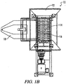
- an embodiment of the hinged hopper assembly 10 includes a hopper 12 for receiving waste, which may fall through an inlet 14 into a shredder 16.
- the hinged hopper 10 includes a gate 18, which is operably connected to a first hydraulic cylinder 20. The cylinder 20 may be used to move the gate 18 into a position blocking the inlet 14, to limit or prevent waste moving from the hopper 12 into the shredder 16.
- the hinged hopper 10 additionally includes a hinge upon which the hopper 12 may pivot away from the shredder 16.
- the hopper 12 may be pivoted away from the shredder 16 either manually, or with the assistance of a second hydraulic cylinder 22. In this manner, the shredder 16 may be exposed to allow for rapid removal of any debris clogging the shredder 16. Once the clogging debris is removed from the shredder 16, the hopper 12 may be pivoted back to its original position, the gate 18 may be opened, and waste may again be received into the hinged hopper assembly 10 for introduction into the shredder 16.
- operational safeguards may be installed according to known design criteria.
- the apparatus of the present invention is a material injection assembly, for transferring solid waste or preprocessed waste to a hydrolyzer.
- Solid waste may be preprocessed, by way of example and not limitation, by reducing its particle size using an apparatus comprising grinders or shredders and removing metal using an apparatus comprising magnetic separators.
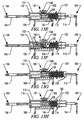
- an embodiment of a material injection assembly 30 of the present invention may receive preprocessed waste via a hopper 32 and transfers the waste through a sliding gate construction 50 to a connected hydrolyzer 80 for further processing.
- the illustrated material injection assembly 30 is supported by a platform 34 and comprises: the hopper 32, a hydraulic cylinder 36, a ram 37 operably connected to the cylinder 36, a pipe sleeve 40, and an in-feed gate assembly 52.
- the gate assembly 52 further comprises a hydraulic cylinder 54 and the sliding gate construction 50, operably connected to the.cylinder 54, which opens and closes an internal passageway 55 (best shown in FIG. 5A ) to an inlet 82 of the hydrolyzer 80.
- the hopper 32 is adapted for receiving waste 68, which typically falls through to the bottom end 38 of the hopper 32 and into the pipe sleeve 40 for processing.
- the hopper 32 may include a static or vibrating grate (not shown) capable of prohibiting large objects from reaching the bottom end 38.
- the grate would allow all solid waste, except for these large objects, to fall from the hopper 32 and into the pipe sleeve 40.
- the ram 37 is situated within the pipe sleeve 40 and is manipulated back and forth within the pipe sleeve 40 by the hydraulic cylinder 36.
- the hydraulic cylinder 36 includes a shaft 43, which may be connected to the ram 37 by any well known connection, such as a pin engagement 45.
- the hydraulic cylinder 36 moves the ram 37 into three positions, which may be described with reference to the contact made between a tenon 46, associated with the cylinder 36, and proximity switches 48a, 48b, and 48c.
- a first distinct position best shown in FIG. 5A wherein the ram 37 is fully extended, is achieved when the tenon 46 contacts a first proximity switch 48a .
- a second distinct position best shown in FIG. 5B wherein the ram 37 is fully withdrawn, is achieved when the tenon 46 contacts a second proximity switch 48b .
- a third position, shown in FIG. 5C is achieved when the tenon 46 contacts a third proximity switch 48c.
- the illustrated sliding gate construction 50 of the gate assembly 52 which opens and closes access through the internal passageway 55 includes a gate plate 56 flanked by a pair of end plates 58a, 58b, which are secured to the pipe sleeve 40 by an attachment collar 59.
- the gate plate 56 is connected by a coupling 53 to shaft 51, driven by hydraulic cylinder 54 to cycle gate plate 56 between end plates 58a, 58b.
- the gate plate 56 is in a closed position, as shown in FIGS. 5A through 5C , the interior of the pipe sleeve 40 is operationally disconnected from the hydrolyzer 80.
- an aperture 63 within gate plate 56 is aligned with the pipe sleeve 40 to permit the flow of waste to the hydrolyzer 80 .
- FIGS. 5A through 5E The manner in which the illustrated material injection assembly 30 may operate will now be discussed with reference to FIGS. 5A through 5E .
- the ram 37 is in the fully extended first position, wherein the tenon 46 is in contact with proximity switch 48a, the gate plate 56 is in a closed position, and waste 68 is introduced into the hopper 32. Waste which has previously been fed through the hopper 32 and is being held within the pipe sleeve 40 is referred herein as "a plug” and is generally designated by numeral 66.
- the plug 66 is referred herein as a "partial plug” 66a when, as shown in FIG. 5C , it does not completely fill the space within the pipe sleeve 40 defined by the gate plate 56 and the ram 37.
- the ram 37 is shown fully in the retracted second position, with the tenon 46 in contact with the proximity switch 48b. In this position the waste 68 is permitted to flow from the hopper 32, through the inlet 38, and into the pipe sleeve 40 together with the partial plug 66.
- FIG. 5C the ram 37 is shown in a partially extended position, with the tenon 46 in contact with the proximity switch 48c. When moved into the partially extended position, ram 37 blocks the flow of waste 68 at the bottom end 38 and forms a complete plug 66 with the newly introduced waste. The gate plate 56 remains in the closed position, allowing the plug 66 to be uniformly compressed.
- FIG. 5D following compression of the plug 66 the gate plate 56 is raised, allowing for access to the hydrolyzer 80.
- the ram 37 is moved into the fully extended first position, forcefully inserting the plug 66 into the hydrolyzer 80.
- the gate plate 56 is returned to the closed position, and the operation is repeated as desired.
- the embodiment of the material injection assembly 30, just described, may be used as part of a system comprising various apparatuses, including a hydrolyzer.
- a hydrolyzer metamorphically processes a volume of waste on a continuous basis.
- the hydrolyzer 80 in this embodiment receives waste material in the form of a plug 66 through the inlet 82, includes a pressure vessel 84 , an exit end 86, an exit port 87, and an attachment collar 88 for operationally connecting to apparatus for further processing.
- the pressure vessel 84 contains a rotating spindled shaft 90 comprising an axle or shaft 92 and a plurality of agitators extending outwardly therefrom.
- the agitators may be of any configuration that permits forward movement of waste material through the pressure vessel.
- two means for agitating and moving are shown, bars 93 and paddles 94 .
- the agitator bars 93 are integral with or otherwise secured to the axle 92 by well known methods including welding or fasteners.
- the paddles 94 are likewise integral with or otherwise secured to the axle 92.
- Each paddle 94 includes a pedestal 97 terminating at a wiper blade 98 with a leading edge 99a and a trailing edge 99b.
- bars 93 or paddles 94 may extend along the entire length of the axle 92, or any combination thereof.
- agitator bars 93 are secured to that section of the axle 92 that is nearer to the inlet 82
- paddles 94 are secured to that section of the axle 92 that is nearer to the exit end 86.
- one purpose is to move material through the pressure vessel 84 while being processed.
- agitators are secured to the axle 92 such that the placement of adjacent individual paddles 94 or bars 93 form a helical pattern along the length of the axle 92.
- This helical pattern facilitates the movement of material from the inlet 82 to the exit end 86 of the hydrolyzer 80, while preventing clogging and promoting self-cleaning.
- the agitator bars 93 form an angle with the axle 92 that is less than ninety degrees.
- the paddles 94 and the agitator bars 93 may be placed in the helical pattern along a portion of or the entire length of the elongated portion 92, depending on the properties of the material being processed by the hydrolyzer 80 and the period of time it is desired that the material remain within the hydrolyzer 80.
- a helical pattern along the entire length of the elongated portion 92 will generally result in the material remaining within the hydrolyzer 80 for a shorter period of time.
- the processed material exiting the hydrolyzer 80 may be further processed by additional apparatus.
- One such embodiment is the material handling apparatus illustrated in FIGS. 11 through 14F .
- One illustrated embodiment of the material handling apparatus 100 best shown in FIGS. 11 and 12 , comprises an inlet 101, a compaction chamber 102, a plunger assembly 104, a containment assembly 105, and a cutter assembly 124.
- the inlet 101 includes a coupling collar 103 for attachment to a cooperating collar, such as the collar 88 of the hydrolyzer 80, shown in FIG. 2 .
- Fluff is received through the inlet 101 and enters the compaction chamber 102, which, includes a plurality of circumferential fins 112, for providing structural support and to resist bending. Once the Fluff has been received by the compaction chamber 102, it is compressed by a plunger assembly 104.
- the plunger assembly 104 matingly attached to the compaction chamber 102 by cooperating collar 110, includes a hydraulic cylinder 106 having a shaft 108 secured to and operating the movement of a ram 109.
- the ram 109 is situated and cycles within the compaction chamber 102 to compress the Fluff. While the fins 112 provide structural support for the compaction chamber 102, they also maintain alignment with the ram 109 as it reciprocates therein.
- the force of the ram 109 on the Fluff is sufficient to produce a compressed block of Fluff 166, shown in FIGS. 13A through 13H , within a volume defined by the compaction chamber 102.
- the term block may be used interchangeably with terms such as plugs and pig to mean a portion of compressed Fluff, and not as a limitation to any particular shape or configuration.
- the stop plate 119 is a structural element of the containment assembly 105, which further comprises a truss 115 and a containment cylinder 116. Cylinder 116 is attached to the truss 115 at one end and to a shaft 117 at the other end. The shaft 117, in turn, terminates at the stop plate 119.
- the stop plate 119 serves as a backstop for the ram 109 of the plunger assembly 104, enabling the Fluff interpositioned between the ram 109 and the stop plate 119 to form a compressed block having dimensions resembling the interior configuration of the compaction chamber 102 and a block forming section 122.
- the illustrated embodiment of the material handling apparatus 100 comprises a block cutter assembly 124.
- the block cutter assembly 124 comprises the block forming section 122 and a hydraulic cylinder 126, attached at one end to a frame 120 at a cross member 125 and attached at the other end to a shaft 127.
- the shaft 127 is attached at a distal end to a knife 128.
- the knife 128 cycles, supported by the frame 120, and includes an aperture 132 configured to be aligned with the compaction chamber 102 such that the block 166 may pass through the aperture 132 into the block forming section 122 before being cut by the knife 128.
- Wheeled carriage assemblies 134, 136 may be provided to enable the material handling apparatus 100 to be supported and mobile. It is contemplated and will be understood by those skilled in the art, that all the component assemblies described herein may be supported by carriage assemblies, such as those shown, or motorized platforms to enable portability of individual assemblies or an entire system.
- FIG. 13A the ram 109 is extended to a position which blocks the flow of Fluff 168 from the inlet 101 into the compaction chamber 102 and the stop plate 119 is positioned adjacent the compaction chamber 102 at the opening to the block forming section 122.
- FIG. 13B the ram 109 is withdrawn to allow Fluff 168 to fall into the compaction chamber 102.
- FIG. 13C the ram 109 is extended to compress Fluff 168 against the stop plate 119. Because plunger assembly 104 exerts more force than cylinder 116, cylinder 116 begins to be overbidden by the block of Fluff 166 pushing against the stop plate 119, such that the stop plate is forced to retreat slightly into the block forming section 122.
- FIG. 13D the ram 109 is shown withdrawn, allowing additional Fluff 168 to be introduced into the compaction chamber 102.
- FIG. 13E the ram is extended, forcing the newly added Fluff 168 against the block 166. The force of the ram 109 against the block 166 pushes stop plate 119 further into the block forming section 122.
- the ram 109 is again withdrawn, as shown in FIG. 13F , allowing still more Fluff 168 to be introduced into the compaction chamber 102.
- the ram 109 is again extended, as shown in FIG. 13G , forcing the newly added Fluff 168 against the block 166.
- the operation of introducing Fluff 168 into the compaction chamber 102 and forcing the newly added Fluff 168 against the compacted block of Fluff 166 to form a more lengthy block of Fluff 166 continues until the capacity of the block forming section 122 is met, that is, the stop plate 119 has fully retreated into the block forming section 122 and the cylinder 116 has been completed overridden, as shown in FIG. 13G and 14A .
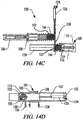
- the block cutting assembly 124 is used to cut a portion of the block 166 held within the block forming section 122, leaving a portion of the block 166 within the chamber 102.
- the cylinder 126 of the block cutting assembly 124 operates to extend the knife 128 and cut the block 166.
- the block cutting assembly 124 moves on the wheeled carriage assembly 136 from a position where the aperture 132 is aligned with the chamber 102, shown in FIGS. 14A and 14B , to a position where the aperture 132 is not aligned with the chamber 102, shown in FIGS. 14C and 14D
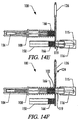
- the material handling apparatus 100 may comprise an expansion chamber 150, to which the aperture 132 becomes aligned.
- the cylinder 116 may operate to extend the stop plate 119, forcing the freshly cut block 166 from the block forming section 122, into the expansion chamber 150.
- the expansion chamber 150 may not be required if the block 166 is of low temperature and pressure; the freshly cut block 166 could simply be expelled from material handling apparatus.
- the block cutting assembly 124 is shown realigned with the chamber 102 ready to cooperatively execute the above-described operation.
- the present disclosure relates to methods for transforming solid waste into useful products, including a reusable, treatable, or readily degradable material, which methods will now be discussed with reference to the embodiment 200 illustrated in FIG. 15 .
- the illustrated method 200 includes the following steps, which are not limited to the order or sequence presented: preprocessing of raw material; transferring preprocessed material to a hydrolyzer; processing the material within the hydrolyzer; transferring processed material, or Fluff, from the hydrolyzer; and extruding or molding the processed material.
- the exemplary method includes a preprocessing step in which the solid waste is shredded, ground, and, if desired, dewatered prior to insertion into a hydrolizer or a bioreactor for processing therein.
- preprocessing step 210 includes, one or more steps resulting in a substantial portion of inorganic material being removed from the waste.
- the method may also include one or more metal removing steps and one or more size reduction steps.
- metals may be removed using magnetic means including an eddy current prior to or after the size reduction steps.
- the size reduction steps may include the use of a grinder, a shredder or other material reduction apparatus used to reduce the incoming particle size of the waste.
- the preprocessing 210 may additionally include a step whereby liquid is extracted from wet portions of the solid waste and redistributed to the dry portions of the solid waste to create a substantially uniform hydration level throughout the volume of preprocessed solid waste.
- the shredded and ground raw material may be transferred, either automatically or manually, to a dewatering press in order to uniformly hydrate the material prior to its introduction into the hydrolyzer, for metamorphic processing of the volume reduced waste.
- the preprocessing step 210 may comprise transforming a solid waste having the first volume and liquid content into a second volume of solid waste wherein the second volume is smaller than the first volume.
- the preprocessed material is transferred to a hydrolyzer whose interior vessel is heated in order to heat the material therein.
- a hydrolyzer includes an outer containment vessel having an exterior jacket and an interior pressure vessel, an airspace exists between the interior vessel and the jacket, and a heated steam inlet and exit are attached to the jacket. and communicate with the air space.
- the step 220 may further include continuously feeding the preprocessed material into the hydrolyzer in predetermined volumes.
- the continuous operation of feeding the material into the hydrolyzer may include the automatic operation of this task by machine.
- the preprocessed material is processed within the interior of the hydrolyzer for a given length of time depending upon the user selected temperature and pressure within the steam jacket and hydrolyzer interior.
- An exemplary temperature of the steam in the outer jacket is about 350 degrees.
- An exemplary pressure is about 82736g N.m -2 (about 120 psi).
- the process could be carried out at other temperatures and pressures, and the exemplary temperature or pressure are not a limitation. As will be understood by those skilled in the art, generally speaking, the greater the temperature and pressure in the hydrolyzer the faster the chemical reactions will occur.
- the selected pressure and temperature acts as a catalyst to speed the chemicals reaction of decomposition of the material within the vessel.
- the raised temperature and pressure environment causes the material to rapidly decompose into its basic constituent elements, and allows them to recombine or remain in their organic cellulose form, and it kills bacteria once living within the material.
- Additional catalysts such as chemicals or additives, may enhance or accelerate the decomposing phase.
- the material exits the hydrolyzer.
- the material is transformed into a sterile aggregate cellulose composite material, sometime referred to herein as "Fluff".
- the Fluff is a mixture of cellulose fibers and other elements present in the material prior to processing, including chemicals or additives added to the material, if any.
- the step 240 of removing the Fluff from the hydrolyzer may further include continuously removing the Fluff from the hydrolyzer in predetermined volumes.
- the continuous operations of removing the solid waste from of the hydrolyzer may include the automatic operation of this task by machine.
- the Fluff may be dried and distributed for use or remanufactured into articles, such as compressed bales of material or other molded or extruded articles.
- articles such as compressed bales of material or other molded or extruded articles.
- Chemical or natural additives may be added to enhance the characteristics of the Fluff or the remanufactured articles.
- Fluff may be used to manufacture useful articles including plasticene cross ties, building materials including bricks, boards, and blocks of all sizes, and insulation, or applied to useful applications such as compost and land reclamation fill.
- the exemplary method 200 comprises additional steps. For example, a drying step, a purification step wherein inorganic materials are substantially removed from the waste, and a step wherein the Fluff is mixed with plastics, chemicals, or other performance enhancing additives.
- An exemplary product made by the exemplary method may be described as a composite material derived from a process for transforming solid waste, such as a process including the steps described above.
Description
- The present invention relates to solid waste disposal, and, more particularly, to transforming solid waste into useful products, including a reusable, treatable, or readily degradable material.
- Solid waste disposal can generally be defined as the disposal of normally solid or semisolid materials, resulting from human and animal activities, which are useless, unwanted, or hazardous. "Solid waste" generally comprises, "garbage," including decomposable wastes from food; "rubbish" including combustible decomposable wastes, such as paper, wood, and cloth, or non-combustible decomposable wastes, such as metal, glass, and ceramics; "ashes" including the residue of the combustion of solid fuels; "large wastes" including demolition and construction debris and trees; dead animals; "sewage treatment solids" including the material retained on sewage-treatment screens, settled solids, and biomass sludge; "industrial wastes" including chemicals, paints, and sand; "mining wastes" including slag heaps and coal refuse piles; and "agricultural wastes" including farm animal manure and crop residues.
- Modem management of waste disposal began in the late 1800's and by the 1890's more than half of America's cities utilized some system of collection and disposal of refuse. Such refuse often included ashes, food and dry rubbish, which each had a specific secondary use. Food scraps were fed to animals on the farms, the ashes filled potholes in roads and "unhealthy" swamps, and the dry rubbish was sorted for valuables. Rags, paper and the like, made more paper, and metals went back into production as reusable goods. The secondary use of much early refuse made such disposal systems as modem day landfills unnecessary.
- By the 1930's food scraps, rags and paper were mixed together and carted to an incinerator. Incineration was cheaper and easter than sorting the refuse for secondary use because the mixture of materials could be collected at one time and burned together, and incineration continues to be used today.
- Incinerators of conventional design burn refuse on moving grates in refractory-lined chambers. The combustible gases and the solids they carry are burned in secondary chambers. In addition to heat, the products of incineration include the normal primary products of combustion including carbon dioxide and water, as well as oxides of sulfur and nitrogen and other gaseous pollutants. The nongaseous products are fly ash and unburned solid residue.
- In the 1940's, sanitary landfills proliferated. A sanitary landfill is generally considered the cheapest satisfactory means of waste disposal, but only if suitable land is within economic range of the source of the wastes. Typically, collection and transportation costs account for seventy-five percent of the total cost of solid waste management. In a modern landfills, refuse is spread in thin layers, each of which is compacted by heavy industrial equipment such as bulldozers before the next layer is spread. When about 3 meters of refuse has been laid down, it is covered by a thin layer of clean earth which also is compacted.
- In any event, by the 1950's, with the explosion of consumer products focusing on disposability, the amount of refuse generated increased dramatically. In fact, some reports suggest that by the 1970's five pounds of garbage per capita were discarded daily as compared to 2.7 pounds in the 1920's. In the 1980's, the public began to appreciate that congested landfills were polluting drinking water. At this time, recycling and composting began a resurgence and, today, they are at the forefront of community living.
- Recycling and composting is recognized as an efficient way to handle organic solid waste and to reintroduce nutrients into nutrient depleted soil. In addition, recycling has transformed discarded materials, such as cellulose, wood, grass, leaves, cardboard, pallets, tree limbs, etc., plastics (polystyrene, polyethylene, polypropylene, PVC, etc.), glass, and ceramics into reusable materials.
- Although the benefits of recycling are recognized, by far the most comnion method of disposing of solid wastes in the United States is the deposition of such wastes on land-or in "landfills," which may account, for more than ninety percent of the nation's municipal refuse. Incineration accounts for most of the remainder, whereas composting of solid wastes accounts for only an insignificant amount.
- With regard to landfills, although pollution of surface and groundwater is believed to be minimized by taking such precautions as: lining and contouring the fill; compacting and planting the cover; selecting proper soil; diverting upland drainage; and placing wastes in sites not subject to flooding or high groundwater levels, such pollution remains a concern. Gases are generated in landfills through anaerobic decomposition of organic solid waste. If a significant amount of methane is present, it may be explosive; therefore, proper venting and burning of the methane gases are often necessary to eliminate or alleviate these dangerous conditions.
- With regard to incineration, the process introduces harmful by-products and pollutants into the atmosphere and incineration methods are known to destroy the useful hemicellulose component of woody cellulose materials container in solid waste (see the explanation set forth below).
- Because landfill and incineration methods of disposal are known to pose significant environmental problems and concerns for the municipality, government, private industry, and individuals, recycling has become an attractive alternative. The treatment and handling of solid waste for reuse is particularly attractive. Such treatment and handling of solid waste is referred to herein as "resource recovery."
- Hammer mills incorporate rotating drums with free-floating hammers. They are designed to spin at a relatively high speed, such that material placed in front of the rotating drum is impacted by the hammers. Thus, hammer mills do not cut, shred or tear the material, but rely on impact forces to pulverize the material.
- Grinders also incorporate rotating drums; however, grinder drums generally have a flat abrasive surface or include integral cutters, such that material placed in contact with the rotating drum is cut, torn, and shredded.
- Shredders typically incorporate a pair of rotatable parallel shafts, having spaced apart cutters, which pull the material downward between the parallel shafts, causing the material to be shredded. In an overload condition, the rotation of the shafts may be momentarily reversed before resuming the shredding rotations, however, when a typical shredder becomes clogged with debris, it must be shut down for a lengthy de-clogging process.
- Pressure vessel apparatuses, such as hydrolyzers, may be used for processing organic material, for example, animal carcasses or parts thereof, including organic wastes generated during meat and poultry production for human consumption. Such processing may be termed "metamorphic," in that a change of physical form, structure, or substance to the components of the waste is effected. Known hydrolyzer apparatuses have various shortcomings. For example, these conventional vessels are prone to repeated and continuous clogging when trying to process certain waste material and thus require repeated down time intervals and disassembly to empty the interior of the vessel.
- Turning now, from the machines, to the methods of resource recovery systems, certain resource recovery methods can be considered thermal processes, generally, but more specifically, combustion processes or pyrolysis processes. Pyrolysis, also called destructive distillation, is the process of chemically decomposing solid wastes by the introduction of heat in an oxygen-reduced atmosphere. This results in a gas stream containing primarily hydrogen, methane, carbon monoxide, carbon dioxide, and various other gases and inert ash, depending on the organic characteristics of the material being pyrolyzed.
- Another approach to the treatment of waste is known as a "wet pulping process." In a wet pulping process the incoming refuse is mixed with water and ground into a slurry in an apparatus referred to as a wet pulper-a machine that is similar to a large kitchen disposal unit. Large pieces of metal and other non-pulpable materials are separated by a magnetic separator, and the residue is used as landfill. The slurry from the pulper goes into a centrifugal device called a liquid cyclone, which separates heavier non-combustibles such as glass, metals, and ceramics. The heavy fraction goes to a glass and metal recovery system; the light fraction goes to a paper and fiber recovery system. Combustible residues are mixed with sewage sludge, mechanically dewatered, and incinerated. Noncombustible residues are used as landfill.
- These aforementioned processes are among those which have been used in an attempt to transform solid waste into a more manageable form, however, the resulting end-product of these processes is not always useful.
- The useful components of solid waste and the problems associated with extracting such components using known resource recovery systems will now be discussed. "Woody" cellulose materials, found in most solid waste, includes cellulose, a carbohydrate of unknown molecular structure, but which may be represented by the empirical formula (C6H10O5)x; lignin, an organic substance closely allied to cellulose and forming the essential part of woody fibers; and hemicellulose, which serves as the binding agent for the constituent elements of the wood-like cellulose molecule and is useful in applications such as papermaking.
- The hemicellulose is composed of two general classes of substances: (1) those collectively called xylons whose molecules are formed by polymerization of certain forms of pentose sugars, and (2) glucomannans, whose molecules are formed by polymerization of certain forms of forms of hexose sugars, primarily glucose and mannose. These substances cannot be readily disassociated from cellulose-containing material without being destroying. For example, combustion and pyrolysis processes are known to destroy the hemicellulose and prevent its use as a bonding agent to form other molecules of cellulose. In this regard, many techniques used in resource recovery systems, including, oxidation, hydrogenation, alkaline hydrolysis, pyrolysis and use of powerful solvents, have limited utility because of their harsh and destructive nature.
- To summarize, the existing waste disposal systems have a variety of problems. Use of landfills and incinerators ignore the useful components solid waste and pose- significant environmental problems
- Existing apparatuses of resource recovery systems are inefficient in that they must be shut down for significant periods of time when becoming clogged with debris.
- Additionally, existing methods of resource recovery systems incorporate harsh techniques, which not only destroy useful components of solid waste, such as hemicellulose, but also, in the case of certain solvents and oxidants, pose environmental concerns.
- Furthermore, in all known methods of resource recovery systems, the resultant product may include microbes or microorganisms that require further consideration prior to disposal. In such cases the resultant products are believed to remain waste materials not suitable for use or transformation into useful articles.
- Examples of known arrangements for injecting waste material into a waste processing apparatus are disclosed in
US-A-4099457 ,US-A-2780987 , which discloses a material injection assembly in accordance with the preamble of claim 1, andUS-A-3983009 . - Accordingly, there remains a need in the art for apparatuses and methods of resource recovery which satisfactorily addresses the problems set forth above.
- The present invention adresses above identified needs, and others, by providing an efficient material injection assembly which can be used in apparatuses and methods for transforming solid waste into useful products, including a reusable, treatable, or readily degradable material.
- The apparatuses making use of the material injection assembly of the present invention include: a hinged hopper assembly which allows for the rapid removal of debris clogging a particle size reducing apparatus, such as a shredder; a material injection assembly, for transferring preprocessed waste material for further processing; a hydrolyzer, for metamorphically processing volumes of waste on a continuous basis; and a material handling apparatus, for shaping material exiting a hydrolyzer, a bioreactor, or other processing machine. The methods making use of the material injection assembly of the present invention include methods for the use of the above mentioned apparatuses, alone or in cooperation with other machines, and a method transforming solid waste into a useful material.
- The hinged hopper assembly, as mentioned,, allows for the rapid removal of objects that cannot be processed by any of the particle size reduction apparatus well known by those skilled in the art. Providing for rapid removal of objectionable debris keeps the particle size reduction apparatus from being damaged or shut down to remove clogs. An embodiment of the hinged hopper assembly includes a hopper adapted for receiving and delivering waste to a shredder. The hinged hopper assembly includes a gate, which may be position to block the flow of waste from the hopper into the shredder. The hinged hopper assembly additionally includes a hinge, upon which the hopper may pivot to expose the shredder. In this manner, the shredder may be exposed to allow for rapid removal of any clogging debris. Once the clogging debris is removed from the shredder, the hopper may be pivoted back to its original position, the gate may be opened, and waste may again be received into the hinged hopper assembly for introduction into the shredder.
- The apparatus of the present invention is a material injection assembly in accordance with claim 1, for transferring solid waste or preprocessed waste material to a hydrolyzer. Preprocessed waste may be receives via a hopper and transferred to a connected hydrolyzer for further processing. An embodiment includes: the hopper; a pipe sleeve; a ram contained within the pipe sleeve and operably connected to a hydraulic cylinder, which moves the ram back and forth within the pipe sleeve, and an in-feed gate assembly, including a sliding gate operated by a hydraulic cylinder, which opens and closes a passageway to the hydrolyzer.
- The hopper receives waste and delivers it to the pipe sleeve for processing. The ram may be placed by the attached hydraulic cylinder in three positions within the pipe sleeve: a first, fully extended position; a second, fully withdrawn position; and a third position, in between the first two positions. While in the first and third positions, the ram blocks the passageway from the hopper into the pipe sleeve. While the ram is in the second position, waste is allowed to pass from the hopper into the pipe sleeve.
- The embodiment of the material injection assembly is operated in the following manner. The ram is placed in the fully extended first position, the gate is placed in a closed position, and waste is introduced into the hopper. Waste that has previously been introduced into the material injection assembly is held in a portion of the pipe sleeve and is referred to as "a partial plug." In any event, after the waste has been placed in the hopper, the ram is withdrawn and to the second position, allowing the waste to fall from the hopper into the pipe sleeve along side the partial plug. Next, the ram is moved into the third position, which pushes the newly introduced waste against the partial plug to form, what is refer to as, "a complete plug." The gate remains in the closed position, allowing the complete plug to be uniformly compressed. Following compression of the plug, the gate is raised, allowing for communication between the pipe sleeve and the hydrolyzer. The ram is then moved into the fully extended first position, forcefully inserting the plug into the hydrolyzer. Finally, the gate is returned to the closed position, and the operation is repeated as desired.
- The embodiment of the material injection assembly, just described, may be used as part of a system comprising various apparatuses, including a hydrolyzer. One such hydrolyzer that may be used is a hydrolyzer, which is designed to metamorphically process a volume of waste on a continuous basis. An embodiment of the hydrolyzer receives waste material through an inlet, carries it through a pressure vessel for processing and ultimate expels processed material through an exit port.
- The pressure vessel contains a rotating shaft having an plurality of paddles extending outwardly therefrom. Additionally, the shaft includes a plurality of agitators, extending outwardly therefrom. The agitators may be of any configuration that permits formed movement of waste material through the pressure vessel, for example, paddles or bars. In the embodiment of the hydrolyzer, the agitator bars are secured to a section of the shaft that is nearer to the inlet, while the paddles are secured to a section of the shaft that is nearer to the exit port. However, in embodiments which do not incorporate agitator bars, the paddles may extend along the entire length of the shaft. Whatever the configuration of the agitators, one purpose is to move material through the pressure vessel while being processes.
- In any event, in the embodiment, both the paddles and the bars are secured to the shaft such that the placement of adjacent individual paddles and bars forms a helical pattern along the length of the shaft. This helical pattern facilitates the movement of material from the inlet to the exit port of the hydrolyzer, while preventing clogging and promoting self-cleaning.
- The paddles and the bars may be placed in the helical pattern along a portion of or the entire length of the shaft, depending on the properties of the material being processed by the hydrolyzer and the period of time it is desired that the material remain within the hydrolyzer. In this regard, a helical pattern along the entire length of the shaft will generally result in the material remaining within the hydrolyzer for a shorter period of time.
- The processed material (sometimes referred to herein as "Fluff") exiting the hydrolyzer may be further processed by additional apparatus, such as material handling apparatus. An embodiment of the material handling apparatus includes an inlet, a compaction chamber, a plunger assembly, a containment assembly, and a cutter assembly.
- Fluff is received through the inlet and enters the compaction chamber, terminating at a stop plate, where it is compressed by the plunger assembly. The plunger assembly includes a ram, situated within the compaction chamber, and a hydraulic cylinder, which is secured to and moves the ram back and forth within the chamber, to compress the Fluff against a stop plate.
- The stop plate is connected to a containment cylinder and is initially held at an interface between the compaction chamber and a block forming section of the apparatus. As the Fluff is compressed against the stop plate by the ram, the containment cylinder is slowly overridden, allowing the stop plate to slowly retreat into the block forming section. Fluff is introduced into the compaction chamber and compressed into the compacted block of Fluff within the apparatus, to form a more lengthy block of Fluff, until the stop plate has fully retreated into the block forming section. At this time, the cutting assembly is used to cut off the portion of the block contained within the block forming section.
- The cutter assembly includes a knife which is attached to and operated by a hydraulic cylinder. The knife is interposed between the compaction chamber and the block forming section and includes an aperture that may be aligned with the compaction chamber, allowing compacted Fluff to pass through the aperture into the block forming section, before being cut.
- In this regard, the knife slides relative to the compaction chamber as it is extended by the cylinder, which action cuts the block of compacted Fluff. In the embodiment, the block forming section is secured to the knife and the cutting action causes the block forming section, containing the freshly cut block, to slide away from the compaction chamber. In the embodiment, the apparatus also contains an expansion chamber having an inlet, to which the aperture of the knife may be aligned following the cutting action, creating a passageway between the block forming section and the expansion chamber. The stop plate may then be extended by the containment cylinder, forcing the freshly cut block from the block forming section, into the expansion chamber. The knife, and attached block forming section, are ultimately allowed to return to alignment with the compression chamber and the operation may be repeated.
- As mentioned above, in addition to apparatuses used in solid waste disposal, the present disclosure relates to methods for using the above mentioned apparatuses, alone or in cooperation with other machine, and to other methods for transforming solid waste into a reusable, treatable, or readily degradable material.
- An embodiment of one method includes the following steps: preprocessing of raw material; transferring preprocessed material to a hydrolyzer; processing the material within the hydrolyzer; transferring processed material, or Fluff, from the hydrolyzer; and extruding or molding the processed material.
- The preprocessing step of the embodiment is one in which the solid waste is shredded, ground, and, if desired, dewatered prior to insertion into a hydrolizer or a bioreactor for processing. Preprocessing may also include one or more steps to remove substantial portion of inorganic material, such as metals, from the waste. For example, the waste could be preprocessed to remove ferrous metals, then the waste may be subjected to one or more size reduction apparatuses, and then the waste could be preprocessed to remove non-ferrous metals. The preprocessing may additionally include a step whereby liquid is extracted from wet portions of the solid waste and redistributed to the dry portions of the solid waste to create a substantially uniform hydration level throughout the volume of reprocessed solid waste.
- Next, the preprocessed material is transferred to a hydrolyzer whose interior vessel is heated in order to heat the material therein. The hydrolyzer includes an outer containment vessel having an exterior jacket and an interior pressure vessel. An airspace exists between the exterior jacket and the interior vessel. A heated steam inlet and exit port are attached to the jacket and communicate with the air space.
- The preprocessed solid waste is processed within the interior of the hydrolyzer for a given length of time, which will vary depending upon the temperature and pressure within the steam jacket and hydrolyzer interior. Generally, the greater the temperature and pressure in the hydrolyzer, the faster the chemical reactions will occur. The pressure and temperature, in conjunction with the preprocessed composition of the material being processed, act as the catalyst to speed the chemical reaction of decomposition of the material within the hydrolyzer. This high temperature and pressure environment causes the material to rapidly decompose into its basic constituent elements, and allows them to recombine or remain in their organic cellulose form, and it kills any bacteria associated with the material.
- After the allotted time within the hydrolyzer has elapsed, the material exits the hydrolyzer as "Fluff." The Fluff is a mixture of cellulose fibers and other elements present in the material prior to processing. The Fluff is then dried and may be remanufactured into useful articles, such as compressed bales of material or other molded or extruded articles. Chemical or natural additives may be added to enhance the characteristics of the material or add supplemental material characteristics as needed. In any case, Fluff can be used to manufacture plasticene cross ties, and building materials such as bricks, boards and blocks, etc., or it may be naturally land applied as compost material.
-
-
FIG. 1A is a side view of an embodiment of a hinged hopper; -
FIG. 1B is a top view of the embodiment of the hinged hopper ofFIG. 1A ; -
FIG. 2 is a side view of an embodiment of the material injection assembly of the present invention connected to an embodiment of a hydrolyzer; -
FIG. 3 is an enhanced side view of the material injection assembly ofFIG. 2 ; -
FIG. 4 is a top view of the material injection assembly ofFIG. 3 ; -
FIGS. 5A through 5E are various operational views of the material injection assembly ofFIG. 4 , as seen from longitudinal cross-section line A-A; -
FIG. 6 includes the assemblies shown inFIG. 2 , wherein the hydrolyzer is shown in longitudinal cross-section; -
FIG. 7 shows the shaft of the hydrolyzer ofFIG. 6 ; -
FIG. 8 shows the shaft ofFIG. 7 , as seen from the transverse cross-section line B-B; -
FIG. 9 shows an alternate embodiment of the shaft ofFIG. 8 ; -
FIG. 10 shows the shaft ofFIG. 7 , as seen from the transverse cross-section line C-C; -
FIG. 11 is a top view of an embodiment of a material handling assembly; -
FIG. 12 shows the material handling apparatus ofFIG. 11 , as seen from longitudinal cross-section line D-D; -
FIGS. 13A through 13H are various operational views of the material handling assembly ofFIG. 12 ; -
FIGS. 14A ,14C ,14E, and 14F are various operational views of the material handling assembly ofFIG. 12 , as seen from longitudinal cross-section line E-E; -
FIGS. 14B and14D are end views of the material handling apparatus ofFIG. 11 ; and -
FIG. 15 is a flow chart illustrating an embodiment of a method. - The present diclosure relates to solid waste disposal and includes apparatuses, systems, and methods for transforming solid waste into useful material.
- Embodiments of the apparatuses, which may be combined to create an embodiment of a system for transforming solid waste into useful material, may comprise the following: apparatuses to reduce the particle size of the waste (e.g., hammer mills, grinders, shredders); apparatuses to quickly remove objects which cannot be processed by the particle size reducing apparatuses (e.g., a hinged hopper assembly); apparatuses to remove metal (e.g., magnetic separators); apparatuses to separate components of the waste based on weight or size; apparatuses for transferring preprocessed waste material (e.g., a material injection assembly); apparatuses for decomposing the waste material (e.g., a hydrolyzer); apparatuses for transferring material from a hydrolyzer (e.g., a processed material handling apparatus); and apparatuses for shaping material exiting a hydrolyzer (e.g., a material handling apparatus).
- One apparatus is a hinged hopper assembly, which allows for the rapid removal of objects that cannot be processed by any of the particle size reduction apparatuses well known by those skilled in the art Providing for rapid removal of objectionable debris prevents the particle size reduction apparatus from being damaged or shut down to remove clogs. Turning now to the drawings, wherein like numerals reference like elements throughout the various views, with reference to
FIGS. 1A and1B , an embodiment of the hingedhopper assembly 10 includes ahopper 12 for receiving waste, which may fall through aninlet 14 into ashredder 16. The hingedhopper 10 includes agate 18, which is operably connected to a firsthydraulic cylinder 20. Thecylinder 20 may be used to move thegate 18 into a position blocking theinlet 14, to limit or prevent waste moving from thehopper 12 into theshredder 16. - The hinged
hopper 10 additionally includes a hinge upon which thehopper 12 may pivot away from theshredder 16. Thehopper 12 may be pivoted away from theshredder 16 either manually, or with the assistance of a secondhydraulic cylinder 22. In this manner, theshredder 16 may be exposed to allow for rapid removal of any debris clogging theshredder 16. Once the clogging debris is removed from theshredder 16, thehopper 12 may be pivoted back to its original position, thegate 18 may be opened, and waste may again be received into the hingedhopper assembly 10 for introduction into theshredder 16. As will be understood by those skilled in the art, operational safeguards may be installed according to known design criteria. - The apparatus of the present invention is a material injection assembly, for transferring solid waste or preprocessed waste to a hydrolyzer. Solid waste may be preprocessed, by way of example and not limitation, by reducing its particle size using an apparatus comprising grinders or shredders and removing metal using an apparatus comprising magnetic separators. With reference to
FIG. 2 , generally speaking, an embodiment of amaterial injection assembly 30 of the present invention may receive preprocessed waste via ahopper 32 and transfers the waste through a slidinggate construction 50 to aconnected hydrolyzer 80 for further processing. - Turning now to
FIGS. 3 and4 , more specifically, the illustratedmaterial injection assembly 30 is supported by aplatform 34 and comprises: thehopper 32, ahydraulic cylinder 36, aram 37 operably connected to thecylinder 36, apipe sleeve 40, and an in-feed gate assembly 52. Thegate assembly 52 further comprises ahydraulic cylinder 54 and the slidinggate construction 50, operably connected to the.cylinder 54, which opens and closes an internal passageway 55 (best shown inFIG. 5A ) to aninlet 82 of thehydrolyzer 80. - With reference to
FIGS. 5A and5B , thehopper 32 is adapted for receivingwaste 68, which typically falls through to thebottom end 38 of thehopper 32 and into thepipe sleeve 40 for processing. In this regard, it is contemplated that thehopper 32 may include a static or vibrating grate (not shown) capable of prohibiting large objects from reaching thebottom end 38. The grate would allow all solid waste, except for these large objects, to fall from thehopper 32 and into thepipe sleeve 40. Theram 37 is situated within thepipe sleeve 40 and is manipulated back and forth within thepipe sleeve 40 by thehydraulic cylinder 36. Thehydraulic cylinder 36 includes ashaft 43, which may be connected to theram 37 by any well known connection, such as apin engagement 45. In this embodiment, thehydraulic cylinder 36 moves theram 37 into three positions, which may be described with reference to the contact made between atenon 46, associated with thecylinder 36, andproximity switches - Specifically, a first distinct position best shown in
FIG. 5A , wherein theram 37 is fully extended, is achieved when thetenon 46 contacts afirst proximity switch 48a. A second distinct position best shown inFIG. 5B , wherein theram 37 is fully withdrawn, is achieved when thetenon 46 contacts asecond proximity switch 48b. A third position, shown inFIG. 5C , is achieved when thetenon 46 contacts athird proximity switch 48c. When thetenon 46 contacts one of theswitches gate construction 50. - Referring again to
FIG. 5A , the illustrated slidinggate construction 50 of thegate assembly 52, which opens and closes access through theinternal passageway 55 includes agate plate 56 flanked by a pair ofend plates pipe sleeve 40 by anattachment collar 59. Thegate plate 56 is connected by acoupling 53 toshaft 51, driven byhydraulic cylinder 54 tocycle gate plate 56 betweenend plates gate plate 56 is in a closed position, as shown inFIGS. 5A through 5C , the interior of thepipe sleeve 40 is operationally disconnected from thehydrolyzer 80. However, when thegate plate 56 is in an open position, as shown inFIGS. 5D and5E , anaperture 63 withingate plate 56 is aligned with thepipe sleeve 40 to permit the flow of waste to thehydrolyzer 80. - The manner in which the illustrated
material injection assembly 30 may operate will now be discussed with reference toFIGS. 5A through 5E . Referring toFIG. 5A , theram 37 is in the fully extended first position, wherein thetenon 46 is in contact withproximity switch 48a, thegate plate 56 is in a closed position, andwaste 68 is introduced into thehopper 32. Waste which has previously been fed through thehopper 32 and is being held within thepipe sleeve 40 is referred herein as "a plug" and is generally designated bynumeral 66. Theplug 66 is referred herein as a "partial plug" 66a when, as shown inFIG. 5C , it does not completely fill the space within thepipe sleeve 40 defined by thegate plate 56 and theram 37. - Referring now to
FIG. 5B , theram 37 is shown fully in the retracted second position, with thetenon 46 in contact with theproximity switch 48b. In this position thewaste 68 is permitted to flow from thehopper 32, through theinlet 38, and into thepipe sleeve 40 together with thepartial plug 66. Turning now toFIG. 5C , theram 37 is shown in a partially extended position, with thetenon 46 in contact with theproximity switch 48c. When moved into the partially extended position, ram 37 blocks the flow ofwaste 68 at thebottom end 38 and forms acomplete plug 66 with the newly introduced waste. Thegate plate 56 remains in the closed position, allowing theplug 66 to be uniformly compressed. - Referring now to
FIG. 5D , following compression of theplug 66 thegate plate 56 is raised, allowing for access to thehydrolyzer 80. Next, as shown inFIG. 5E , theram 37 is moved into the fully extended first position, forcefully inserting theplug 66 into thehydrolyzer 80. Referring back toFIG. 5A , thegate plate 56 is returned to the closed position, and the operation is repeated as desired. - The embodiment of the
material injection assembly 30, just described, may be used as part of a system comprising various apparatuses, including a hydrolyzer. Referring now toFIG. 2 andFIG. 6 , the illustratedhydrolyzer 80 metamorphically processes a volume of waste on a continuous basis. Thehydrolyzer 80 in this embodiment receives waste material in the form of aplug 66 through theinlet 82, includes apressure vessel 84, anexit end 86, anexit port 87, and anattachment collar 88 for operationally connecting to apparatus for further processing. - Referring now to
FIGS. 6 and7 , thepressure vessel 84 contains arotating spindled shaft 90 comprising an axle orshaft 92 and a plurality of agitators extending outwardly therefrom. The agitators may be of any configuration that permits forward movement of waste material through the pressure vessel. By way of illustration and not limitation, two means for agitating and moving are shown, bars 93 and paddles 94. The agitator bars 93 are integral with or otherwise secured to theaxle 92 by well known methods including welding or fasteners. Thepaddles 94 are likewise integral with or otherwise secured to theaxle 92. Eachpaddle 94 includes apedestal 97 terminating at awiper blade 98 with aleading edge 99a and a trailingedge 99b. It is contemplated that either bars 93 or paddles 94 may extend along the entire length of theaxle 92, or any combination thereof. In the illustrated embodiment of thehydrolyzer 80, agitator bars 93 are secured to that section of theaxle 92 that is nearer to theinlet 82 , while thepaddles 94 are secured to that section of theaxle 92 that is nearer to theexit end 86. Whatever the configuration of the agitators, one purpose is to move material through thepressure vessel 84 while being processed. - As shown in
FIGS. 7 through 10 , agitators are secured to theaxle 92 such that the placement of adjacentindividual paddles 94 orbars 93 form a helical pattern along the length of theaxle 92. This helical pattern facilitates the movement of material from theinlet 82 to the exit end 86 of thehydrolyzer 80, while preventing clogging and promoting self-cleaning. With reference toFIGS. 8 and 9 , in the embodiment of thehydrolyzer 80, the agitator bars 93 form an angle with theaxle 92 that is less than ninety degrees. Thepaddles 94 and the agitator bars 93 may be placed in the helical pattern along a portion of or the entire length of theelongated portion 92, depending on the properties of the material being processed by thehydrolyzer 80 and the period of time it is desired that the material remain within thehydrolyzer 80. In this regard, a helical pattern along the entire length of theelongated portion 92 will generally result in the material remaining within thehydrolyzer 80 for a shorter period of time. - The processed material (sometimes referred to herein as "Fluff') exiting the
hydrolyzer 80 may be further processed by additional apparatus. One such embodiment is the material handling apparatus illustrated inFIGS. 11 through 14F . One illustrated embodiment of thematerial handling apparatus 100, best shown inFIGS. 11 and 12 , comprises aninlet 101, acompaction chamber 102, aplunger assembly 104, acontainment assembly 105, and acutter assembly 124. - The
inlet 101 includes acoupling collar 103 for attachment to a cooperating collar, such as thecollar 88 of thehydrolyzer 80, shown inFIG. 2 . Fluff is received through theinlet 101 and enters thecompaction chamber 102, which, includes a plurality ofcircumferential fins 112, for providing structural support and to resist bending. Once the Fluff has been received by thecompaction chamber 102, it is compressed by aplunger assembly 104. - The
plunger assembly 104, matingly attached to thecompaction chamber 102 by cooperatingcollar 110, includes ahydraulic cylinder 106 having ashaft 108 secured to and operating the movement of aram 109. Theram 109 is situated and cycles within thecompaction chamber 102 to compress the Fluff. While thefins 112 provide structural support for thecompaction chamber 102, they also maintain alignment with theram 109 as it reciprocates therein. The force of theram 109 on the Fluff is sufficient to produce a compressed block ofFluff 166, shown inFIGS. 13A through 13H , within a volume defined by thecompaction chamber 102. It will be understood by those skilled in the art that the term block may be used interchangeably with terms such as plugs and pig to mean a portion of compressed Fluff, and not as a limitation to any particular shape or configuration. - Referring still to
FIGS. 11 and 12 , thestop plate 119 is a structural element of thecontainment assembly 105, which further comprises atruss 115 and acontainment cylinder 116.Cylinder 116 is attached to thetruss 115 at one end and to ashaft 117 at the other end. Theshaft 117, in turn, terminates at thestop plate 119. Thestop plate 119 serves as a backstop for theram 109 of theplunger assembly 104, enabling the Fluff interpositioned between theram 109 and thestop plate 119 to form a compressed block having dimensions resembling the interior configuration of thecompaction chamber 102 and ablock forming section 122. - The illustrated embodiment of the
material handling apparatus 100 comprises ablock cutter assembly 124. With reference toFIGS. 11, 12 ,14B and14D , theblock cutter assembly 124 comprises theblock forming section 122 and ahydraulic cylinder 126, attached at one end to aframe 120 at across member 125 and attached at the other end to ashaft 127. Theshaft 127 is attached at a distal end to aknife 128. Theknife 128 cycles, supported by theframe 120, and includes anaperture 132 configured to be aligned with thecompaction chamber 102 such that theblock 166 may pass through theaperture 132 into theblock forming section 122 before being cut by theknife 128. -
Wheeled carriage assemblies material handling apparatus 100 to be supported and mobile. It is contemplated and will be understood by those skilled in the art, that all the component assemblies described herein may be supported by carriage assemblies, such as those shown, or motorized platforms to enable portability of individual assemblies or an entire system. - The manner in which the illustrated embodiment of the
material handling apparatus 100 operates will now be discussed with reference toFIGS. 13A through 13H , and then with reference toFIGS. 14A through 14D . Referring first toFIG. 13A , theram 109 is extended to a position which blocks the flow ofFluff 168 from theinlet 101 into thecompaction chamber 102 and thestop plate 119 is positioned adjacent thecompaction chamber 102 at the opening to theblock forming section 122. Turning toFIG. 13B , theram 109 is withdrawn to allowFluff 168 to fall into thecompaction chamber 102. As shown inFIG. 13C , theram 109 is extended to compressFluff 168 against thestop plate 119. Becauseplunger assembly 104 exerts more force thancylinder 116,cylinder 116 begins to be overbidden by the block ofFluff 166 pushing against thestop plate 119, such that the stop plate is forced to retreat slightly into theblock forming section 122. - Turning now to
FIG. 13D , theram 109 is shown withdrawn, allowingadditional Fluff 168 to be introduced into thecompaction chamber 102. Referring toFIG. 13E , the ram is extended, forcing the newly addedFluff 168 against theblock 166. The force of theram 109 against theblock 166 pushes stopplate 119 further into theblock forming section 122. - The
ram 109 is again withdrawn, as shown inFIG. 13F , allowing stillmore Fluff 168 to be introduced into thecompaction chamber 102. Theram 109 is again extended, as shown inFIG. 13G , forcing the newly addedFluff 168 against theblock 166. The operation of introducingFluff 168 into thecompaction chamber 102 and forcing the newly addedFluff 168 against the compacted block ofFluff 166 to form a more lengthy block ofFluff 166 continues until the capacity of theblock forming section 122 is met, that is, thestop plate 119 has fully retreated into theblock forming section 122 and thecylinder 116 has been completed overridden, as shown inFIG. 13G and14A . - The
block cutting assembly 124 is used to cut a portion of theblock 166 held within theblock forming section 122, leaving a portion of theblock 166 within thechamber 102. In this regard, with reference toFIGS. 14A through 14D , thecylinder 126 of theblock cutting assembly 124 operates to extend theknife 128 and cut theblock 166. As theknife 128 extends to cut theblock 166, theblock cutting assembly 124 moves on thewheeled carriage assembly 136 from a position where theaperture 132 is aligned with thechamber 102, shown inFIGS. 14A and 14B , to a position where theaperture 132 is not aligned with thechamber 102, shown inFIGS. 14C and 14D - The
material handling apparatus 100 may comprise anexpansion chamber 150, to which theaperture 132 becomes aligned. With reference toFIG. 14E , thecylinder 116 may operate to extend thestop plate 119, forcing the freshly cutblock 166 from theblock forming section 122, into theexpansion chamber 150. Theexpansion chamber 150 may not be required if theblock 166 is of low temperature and pressure; the freshly cutblock 166 could simply be expelled from material handling apparatus. In either event, with reference toFIGS. 13H and14F , theblock cutting assembly 124 is shown realigned with thechamber 102 ready to cooperatively execute the above-described operation. - In addition to apparatuses and systems described above used in solid waste disposal, the present disclosure relates to methods for transforming solid waste into useful products, including a reusable, treatable, or readily degradable material, which methods will now be discussed with reference to the
embodiment 200 illustrated inFIG. 15 . - The illustrated
method 200 includes the following steps, which are not limited to the order or sequence presented: preprocessing of raw material; transferring preprocessed material to a hydrolyzer; processing the material within the hydrolyzer; transferring processed material, or Fluff, from the hydrolyzer; and extruding or molding the processed material. - As shown in
block 210, the exemplary method includes a preprocessing step in which the solid waste is shredded, ground, and, if desired, dewatered prior to insertion into a hydrolizer or a bioreactor for processing therein. It is contemplated that preprocessingstep 210 includes, one or more steps resulting in a substantial portion of inorganic material being removed from the waste. The method may also include one or more metal removing steps and one or more size reduction steps. For example, metals may be removed using magnetic means including an eddy current prior to or after the size reduction steps. The size reduction steps may include the use of a grinder, a shredder or other material reduction apparatus used to reduce the incoming particle size of the waste. - The
preprocessing 210 may additionally include a step whereby liquid is extracted from wet portions of the solid waste and redistributed to the dry portions of the solid waste to create a substantially uniform hydration level throughout the volume of preprocessed solid waste. In that regard, the shredded and ground raw material may be transferred, either automatically or manually, to a dewatering press in order to uniformly hydrate the material prior to its introduction into the hydrolyzer, for metamorphic processing of the volume reduced waste. - To summarize, the
preprocessing step 210 may comprise transforming a solid waste having the first volume and liquid content into a second volume of solid waste wherein the second volume is smaller than the first volume. - As indicated by
step 220, the preprocessed material is transferred to a hydrolyzer whose interior vessel is heated in order to heat the material therein. It is contemplated that one embodiment of the hydrolyzer includes an outer containment vessel having an exterior jacket and an interior pressure vessel, an airspace exists between the interior vessel and the jacket, and a heated steam inlet and exit are attached to the jacket. and communicate with the air space. - The
step 220 may further include continuously feeding the preprocessed material into the hydrolyzer in predetermined volumes. The continuous operation of feeding the material into the hydrolyzer may include the automatic operation of this task by machine. - Referring now to step 230, the preprocessed material is processed within the interior of the hydrolyzer for a given length of time depending upon the user selected temperature and pressure within the steam jacket and hydrolyzer interior. An exemplary temperature of the steam in the outer jacket is about 350 degrees. An exemplary pressure is about 82736g N.m-2 (about 120 psi). Of course, the process could be carried out at other temperatures and pressures, and the exemplary temperature or pressure are not a limitation. As will be understood by those skilled in the art, generally speaking, the greater the temperature and pressure in the hydrolyzer the faster the chemical reactions will occur.
- The selected pressure and temperature, in conjunction with the preprocessed composition of the material, acts as a catalyst to speed the chemicals reaction of decomposition of the material within the vessel. The raised temperature and pressure environment causes the material to rapidly decompose into its basic constituent elements, and allows them to recombine or remain in their organic cellulose form, and it kills bacteria once living within the material. Additional catalysts, such as chemicals or additives, may enhance or accelerate the decomposing phase.
- With reference to step 240, after the allotted time within the hydrolyzer has elapsed, the material exits the hydrolyzer. When the processing is complete, the material is transformed into a sterile aggregate cellulose composite material, sometime referred to herein as "Fluff". The Fluff is a mixture of cellulose fibers and other elements present in the material prior to processing, including chemicals or additives added to the material, if any.
- The
step 240 of removing the Fluff from the hydrolyzer may further include continuously removing the Fluff from the hydrolyzer in predetermined volumes. The continuous operations of removing the solid waste from of the hydrolyzer may include the automatic operation of this task by machine. - Referring now to step 250, the Fluff may be dried and distributed for use or remanufactured into articles, such as compressed bales of material or other molded or extruded articles. Chemical or natural additives may be added to enhance the characteristics of the Fluff or the remanufactured articles. By way of example and not limitation, Fluff may be used to manufacture useful articles including plasticene cross ties, building materials including bricks, boards, and blocks of all sizes, and insulation, or applied to useful applications such as compost and land reclamation fill.
- It is contemplated that the
exemplary method 200 comprises additional steps. For example, a drying step, a purification step wherein inorganic materials are substantially removed from the waste, and a step wherein the Fluff is mixed with plastics, chemicals, or other performance enhancing additives. An exemplary product made by the exemplary method may be described as a composite material derived from a process for transforming solid waste, such as a process including the steps described above. - The above-described embodiments of the present invention are merely possible examples of implementations, merely set forth for a clear understanding of the principles of the invention. Many variations and modifications may be made to the above-described embodiment(s) of the invention. All such modifications and variations are intended to be within the scope of this disclosure and the present invention as defined by the appended claims.
Claims (5)
- A material injection assembly for transferring waste to a waste processing apparatus, comprising:a sleeve (40) having an inlet (38), through which waste may enter said sleeve, and a passageway (55) through which material may exit said sleeve;a gate (50) including a movable gate plate (56) positioned between said inlet and said passageway, said gate plate (56) defining an aperture (63) configured to pass compressed waste through said passageway; characterized bya ram (37) configured to receivingly operate within said sleeve to compress newly introduced waste and a partial plug of previously introduced waste against the gate to form a complete plug (66).
- The material injection assembly of Claim 1, further comprising a cylinder (36) having a shaft (43) connected to said ram (37), said cylinder for manipulating said ram within said sleeve (40).
- The material injection assembly of Claim 1, further comprising controls for opening and closing said gate plate (56) in relation to the position of said ram (37).
- The material injection assembly of Claim 1, further comprising a hopper (32) for receiving waste, having an open bottom which is operationally connected to said inlet (38) of said sleeve (40).
- The material injection assembly of Claim, 1, further comprising a means for excluding portions of said waste from entering said sleeve (40).
Applications Claiming Priority (1)
| Application Number | Priority Date | Filing Date | Title |
|---|---|---|---|
| PCT/US2004/006038 WO2005092708A1 (en) | 2004-02-27 | 2004-02-27 | Apparatus and method for transforming solid waste into useful products |
Publications (3)
| Publication Number | Publication Date |
|---|---|
| EP1718532A1 EP1718532A1 (en) | 2006-11-08 |
| EP1718532A4 EP1718532A4 (en) | 2010-11-10 |
| EP1718532B1 true EP1718532B1 (en) | 2016-04-06 |
Family
ID=35056081
Family Applications (1)
| Application Number | Title | Priority Date | Filing Date |
|---|---|---|---|
| EP04715755.7A Expired - Lifetime EP1718532B1 (en) | 2004-02-27 | 2004-02-27 | Material injection assembly |
Country Status (4)
| Country | Link |
|---|---|
| US (2) | US20070199613A1 (en) |
| EP (1) | EP1718532B1 (en) |
| HK (1) | HK1094184A1 (en) |
| WO (1) | WO2005092708A1 (en) |
Cited By (1)
| Publication number | Priority date | Publication date | Assignee | Title |
|---|---|---|---|---|
| CN110667928A (en) * | 2019-10-08 | 2020-01-10 | 单井新 | Dermatology is with mixed filling device of traditional chinese medicine |
Families Citing this family (19)
| Publication number | Priority date | Publication date | Assignee | Title |
|---|---|---|---|---|
| EP1718532B1 (en) | 2004-02-27 | 2016-04-06 | Bouldin Corp. | Material injection assembly |
| ES2620425T3 (en) | 2004-09-28 | 2017-06-28 | U.B.Q. Materials Ltd. | Procedure and system to process waste materials |
| WO2006073380A1 (en) | 2004-12-30 | 2006-07-13 | Bouldin Corporation | System and method for processing waste on a continuous basis |
| US7674608B2 (en) | 2007-02-23 | 2010-03-09 | The University Of Toledo | Saccharifying cellulose |
| CN101765663B (en) | 2007-03-14 | 2014-11-05 | 托莱多大学 | Biomass pretreatment |
| US7999355B2 (en) * | 2008-07-11 | 2011-08-16 | Air Products And Chemicals, Inc. | Aminosilanes for shallow trench isolation films |
| MX361924B (en) | 2009-01-15 | 2018-12-19 | U B Q Mat Ltd Star | A composite material and method of preparing the same from substantially unsorted waste. |
| US8771596B2 (en) * | 2010-10-22 | 2014-07-08 | Progressive Recovery, Inc. | Method and apparatus for sterilizing infectious material |
| US8329455B2 (en) | 2011-07-08 | 2012-12-11 | Aikan North America, Inc. | Systems and methods for digestion of solid waste |
| CN104772326A (en) * | 2014-01-09 | 2015-07-15 | 蔡普清 | Garbage compressor |
| US9533310B2 (en) * | 2014-02-03 | 2017-01-03 | Altec Industries, Inc. | Advanced system recovery for feed system |
| WO2015173807A1 (en) | 2014-05-11 | 2015-11-19 | Infimer Technologies Ltd. | Method of separating waste material |
| US9562322B1 (en) | 2014-07-03 | 2017-02-07 | Bouldin Corporation | Fibrous material reprocessing |
| DE202014010155U1 (en) * | 2014-12-22 | 2016-03-24 | Hugo Vogelsang Maschinenbau Gmbh | Solid Ausbringmodul |
| KR101763081B1 (en) | 2016-10-27 | 2017-07-28 | 전희철 | apparatus for crush coco-peat |
| CN109108054A (en) * | 2018-08-20 | 2019-01-01 | 刘日房 | A kind of kitchen garbage dehydration packing apparatus |
| CN112108496B (en) * | 2020-09-09 | 2022-05-10 | 安徽光华铝业制造有限公司 | Recovery plant of old and useless aluminum product |
| US11952715B2 (en) | 2020-10-09 | 2024-04-09 | Bouldin Corporation | Process of transforming waste material into useful material |
| CN113509987B (en) * | 2021-08-24 | 2022-11-01 | 深圳市绿环循环科技有限公司 | Garbage environment-friendly treatment equipment |
Family Cites Families (35)
| Publication number | Priority date | Publication date | Assignee | Title |
|---|---|---|---|---|
| US1490162A (en) * | 1919-11-28 | 1924-04-15 | Fred T Dow | Machine for briquetting peat |
| US2837290A (en) * | 1951-03-05 | 1958-06-03 | Monsanto Chemicals | Feed mill chute with reciprocable knife, to prevent plugging of mill |
| US2780987A (en) | 1953-01-12 | 1957-02-12 | Portco Corp | Wood flour press-method, apparatus, and product |
| US2825377A (en) * | 1956-03-13 | 1958-03-04 | John S Ostrowski | Shredder for leaves |
| US3277850A (en) * | 1965-10-04 | 1966-10-11 | Steve M Jackson | Refuse disposal apparatus |
| US3564993A (en) * | 1968-05-30 | 1971-02-23 | Kunitoshi Tezuka | Compressor for metal scraps and the like |
| US3858504A (en) * | 1970-10-06 | 1975-01-07 | Boyer Jean Jacques | Press for treating household refuse |
| US3792817A (en) * | 1970-10-22 | 1974-02-19 | B Reilly | Method of and apparatus for preparation of waste material for disposal |
| US3850771A (en) * | 1971-01-08 | 1974-11-26 | Biocel Corp | Making of useful products from cellulose-containing garbage |
| US4099457A (en) * | 1972-02-25 | 1978-07-11 | Ab Centralsug | Method for discharging refuse |
| US4110281A (en) * | 1974-02-15 | 1978-08-29 | Gottfried Dreer | Process for the manufacture of fillers from solid waste |
| US3983009A (en) | 1974-03-25 | 1976-09-28 | Neal David A | Method and apparatus for destructive distillation of solid wastes and recovery of distilled products |
| US4153404A (en) * | 1977-09-14 | 1979-05-08 | Turbo Refrigerating Company | Apparatus for producing uniform blocks of ice |
| US4423844A (en) * | 1981-10-02 | 1984-01-03 | Triple/S Dynamics, Inc. | Apparatus for shredding materials |
| US4569649A (en) * | 1984-12-21 | 1986-02-11 | Robert Gross | Machine for making earth blocks |
| US4772430A (en) * | 1985-01-11 | 1988-09-20 | Jgc Corporation | Process for compacting and solidifying solid waste materials, apparatus for carrying out the process and overall system for disposal of such waste materials |
| US4729304A (en) * | 1986-04-03 | 1988-03-08 | Norwood Enterprises | Refuse compactor and transfer chamber |
| US4727804A (en) * | 1987-01-29 | 1988-03-01 | Arrow Steel Inc. | Trash compactor with obliquely disposed compaction chamber and conveyor |
| US5102059A (en) * | 1989-08-07 | 1992-04-07 | Ab Sandarne Industrimaskiner | Disintergrating apparatus |
| US5363758A (en) * | 1992-02-08 | 1994-11-15 | Harris Waste Management Group, Inc. | Baler for polystyrene material |
| US5427650A (en) * | 1992-06-25 | 1995-06-27 | Holloway; Clifford C. | Apparatus and method for preparation for separation, recovery, and recycling of municipal solid waste and the like |
| US5302331A (en) * | 1992-11-30 | 1994-04-12 | Jenkins Robert E | Waste treatment process |
| DE19507958C1 (en) * | 1995-03-07 | 1996-08-08 | Daimler Benz Ag | Process-optimized hammer mill |
| US5667152A (en) * | 1995-05-30 | 1997-09-16 | Mooring; Jonathan E. | Safety system for a wood chipper |
| US5803143A (en) * | 1995-10-23 | 1998-09-08 | Willis; Bobby G. | Method and apparatus for producing wood wafers |
| US5863476A (en) * | 1996-01-16 | 1999-01-26 | Wier; Keith E. | Apparatus and method for compacting and stabilizing granular materials containing hazardous materials |
| US6306248B1 (en) * | 1997-11-20 | 2001-10-23 | The University Of Alabama In Huntsville | Method for transforming diverse pulp and paper products into a homogenous cellulosic feedstock |
| US6017475A (en) * | 1998-04-20 | 2000-01-25 | Bouldin & Lawson, Inc. | Process of transforming household garbage into useful material |
| US6397492B1 (en) * | 1999-05-27 | 2002-06-04 | Msw Patents, Inc. | Apparatus and method for processing municipal solid waste |
| US6237864B1 (en) * | 1999-08-09 | 2001-05-29 | Mtd Products Inc | Chipper shredder chute |
| US6234780B1 (en) * | 1999-09-02 | 2001-05-22 | J.A.T. Engineering Co., Ltd. | Vacuum osmosis and solidification forming machine |
| US6325106B1 (en) * | 1999-11-22 | 2001-12-04 | Esser-Werke Gmbh & Co. Kg | Transport pipe for solid materials |
| US7101164B2 (en) | 2002-08-30 | 2006-09-05 | Bouldin Corporation | Containment system for continuous flow hydrolyzers |
| EP1718532B1 (en) | 2004-02-27 | 2016-04-06 | Bouldin Corp. | Material injection assembly |
| US7303160B2 (en) | 2004-12-30 | 2007-12-04 | Bouldin Corporation | System and method for processing waste on a continuous basis |
-
2004
- 2004-02-27 EP EP04715755.7A patent/EP1718532B1/en not_active Expired - Lifetime
- 2004-02-27 WO PCT/US2004/006038 patent/WO2005092708A1/en active Application Filing
- 2004-02-27 US US10/545,144 patent/US20070199613A1/en not_active Abandoned
-
2007
- 2007-02-01 HK HK07101264.0A patent/HK1094184A1/en not_active IP Right Cessation
-
2013
- 2013-03-14 US US13/803,638 patent/US9555415B2/en not_active Expired - Lifetime
Cited By (1)
| Publication number | Priority date | Publication date | Assignee | Title |
|---|---|---|---|---|
| CN110667928A (en) * | 2019-10-08 | 2020-01-10 | 单井新 | Dermatology is with mixed filling device of traditional chinese medicine |
Also Published As
| Publication number | Publication date |
|---|---|
| HK1094184A1 (en) | 2007-03-23 |
| EP1718532A1 (en) | 2006-11-08 |
| US20140008474A1 (en) | 2014-01-09 |
| US20070199613A1 (en) | 2007-08-30 |
| US9555415B2 (en) | 2017-01-31 |
| EP1718532A4 (en) | 2010-11-10 |
| WO2005092708A1 (en) | 2005-10-06 |
Similar Documents
| Publication | Publication Date | Title |
|---|---|---|
| US9555415B2 (en) | Apparatus and method for transforming solid waste into useful products | |
| US20080048059A1 (en) | System and Method for Processing Waste on a Continuous Basis | |
| KR20170116086A (en) | New methods and apparatus for converting undifferentiated municipal solid waste into geopolymer pellets / briquettes and geopolymer brick / sidewall blocks | |
| US7988830B2 (en) | Waste processing process using acid | |
| US6017475A (en) | Process of transforming household garbage into useful material | |
| KR101744153B1 (en) | Solid waste processing apparatus | |
| PL83188B1 (en) | Method for treating household refuse[us3752059a] | |
| GB2171638A (en) | Process and apparatus for compacting and solidifying solid waste materials, and overall system for disposal of such waste materials | |
| KR100383036B1 (en) | The refuse disposal system and its use method and the preparation method of an alternative fuel utilizing the combustible materials | |
| KR20020015759A (en) | Solid fuel production process of use refuse charact eristic | |
| US7311504B2 (en) | Apparatus for and method of transforming useful material into molded or extruded articles | |
| US11890656B2 (en) | Process for recovering organics from material recovery facility fines | |
| US20040080072A1 (en) | Composite material derived from municipal solid waste | |
| US20040041301A1 (en) | Method for transforming municipal solid waste into useful material | |
| EP1841589B1 (en) | System for processing waste on a continuous basis | |
| KR100582603B1 (en) | solid-fuel preparation method using food sludge | |
| PH12015000047A1 (en) | Wte-process and renewable energy optimization system | |
| JPH11156322A (en) | Treatment of landfill waste | |
| KR100208892B1 (en) | Device for treating organic waste | |
| KR20230132915A (en) | Method and device for producing solid fuel using food waste impurities | |
| KR19980056357A (en) | Vacuum Drying Device for Food Waste Disposal Vehicle | |
| CN110280569A (en) | It is a kind of to live and construction refuse resource utilization process | |
| JPH04260487A (en) | Apparatus and method for treating source-separated waste refuse |
Legal Events
| Date | Code | Title | Description |
|---|---|---|---|
| PUAI | Public reference made under article 153(3) epc to a published international application that has entered the european phase |
Free format text: ORIGINAL CODE: 0009012 |
|
| 17P | Request for examination filed |
Effective date: 20060906 |
|
| AK | Designated contracting states |
Kind code of ref document: A1 Designated state(s): AT BE BG CH CY CZ DE DK EE ES FI FR GB GR HU IE IT LI LU MC NL PT RO SE SI SK TR |
|
| REG | Reference to a national code |
Ref country code: HK Ref legal event code: DE Ref document number: 1094184 Country of ref document: HK |
|
| DAX | Request for extension of the european patent (deleted) | ||
| RAP1 | Party data changed (applicant data changed or rights of an application transferred) |
Owner name: BOULDIN CORP. |
|
| R17P | Request for examination filed (corrected) |
Effective date: 20060906 |
|
| A4 | Supplementary search report drawn up and despatched |
Effective date: 20101013 |
|
| RIC1 | Information provided on ipc code assigned before grant |
Ipc: B09B 3/00 20060101ALI20101007BHEP Ipc: B30B 15/32 20060101ALI20101007BHEP Ipc: B65B 1/20 20060101AFI20051010BHEP |
|
| 17Q | First examination report despatched |
Effective date: 20110110 |
|
| REG | Reference to a national code |
Ref country code: DE Ref legal event code: R079 Ref document number: 602004048984 Country of ref document: DE Free format text: PREVIOUS MAIN CLASS: B65B0001200000 Ipc: B09B0003000000 |
|
| RIC1 | Information provided on ipc code assigned before grant |
Ipc: B30B 9/30 20060101ALI20150813BHEP Ipc: B30B 15/32 20060101ALI20150813BHEP Ipc: B09B 3/00 20060101AFI20150813BHEP |
|
| GRAP | Despatch of communication of intention to grant a patent |
Free format text: ORIGINAL CODE: EPIDOSNIGR1 |
|
| INTG | Intention to grant announced |
Effective date: 20151002 |
|
| GRAS | Grant fee paid |
Free format text: ORIGINAL CODE: EPIDOSNIGR3 |
|
| INTG | Intention to grant announced |
Effective date: 20160118 |
|
| GRAA | (expected) grant |
Free format text: ORIGINAL CODE: 0009210 |
|
| AK | Designated contracting states |
Kind code of ref document: B1 Designated state(s): AT BE BG CH CY CZ DE DK EE ES FI FR GB GR HU IE IT LI LU MC NL PT RO SE SI SK TR |
|
| REG | Reference to a national code |
Ref country code: GB Ref legal event code: FG4D |
|
| REG | Reference to a national code |
Ref country code: AT Ref legal event code: REF Ref document number: 787168 Country of ref document: AT Kind code of ref document: T Effective date: 20160415 Ref country code: CH Ref legal event code: EP |
|
| REG | Reference to a national code |
Ref country code: IE Ref legal event code: FG4D |
|
| REG | Reference to a national code |
Ref country code: DE Ref legal event code: R096 Ref document number: 602004048984 Country of ref document: DE |
|
| REG | Reference to a national code |
Ref country code: NL Ref legal event code: MP Effective date: 20160406 |
|
| PG25 | Lapsed in a contracting state [announced via postgrant information from national office to epo] |
Ref country code: NL Free format text: LAPSE BECAUSE OF FAILURE TO SUBMIT A TRANSLATION OF THE DESCRIPTION OR TO PAY THE FEE WITHIN THE PRESCRIBED TIME-LIMIT Effective date: 20160406 |
|
| REG | Reference to a national code |
Ref country code: HK Ref legal event code: GR Ref document number: 1094184 Country of ref document: HK |
|
| PG25 | Lapsed in a contracting state [announced via postgrant information from national office to epo] |
Ref country code: FI Free format text: LAPSE BECAUSE OF FAILURE TO SUBMIT A TRANSLATION OF THE DESCRIPTION OR TO PAY THE FEE WITHIN THE PRESCRIBED TIME-LIMIT Effective date: 20160406 |
|
| PG25 | Lapsed in a contracting state [announced via postgrant information from national office to epo] |
Ref country code: ES Free format text: LAPSE BECAUSE OF FAILURE TO SUBMIT A TRANSLATION OF THE DESCRIPTION OR TO PAY THE FEE WITHIN THE PRESCRIBED TIME-LIMIT Effective date: 20160406 Ref country code: SE Free format text: LAPSE BECAUSE OF FAILURE TO SUBMIT A TRANSLATION OF THE DESCRIPTION OR TO PAY THE FEE WITHIN THE PRESCRIBED TIME-LIMIT Effective date: 20160406 Ref country code: GR Free format text: LAPSE BECAUSE OF FAILURE TO SUBMIT A TRANSLATION OF THE DESCRIPTION OR TO PAY THE FEE WITHIN THE PRESCRIBED TIME-LIMIT Effective date: 20160707 Ref country code: PT Free format text: LAPSE BECAUSE OF FAILURE TO SUBMIT A TRANSLATION OF THE DESCRIPTION OR TO PAY THE FEE WITHIN THE PRESCRIBED TIME-LIMIT Effective date: 20160808 |
|
| PG25 | Lapsed in a contracting state [announced via postgrant information from national office to epo] |
Ref country code: BE Free format text: LAPSE BECAUSE OF FAILURE TO SUBMIT A TRANSLATION OF THE DESCRIPTION OR TO PAY THE FEE WITHIN THE PRESCRIBED TIME-LIMIT Effective date: 20160406 |
|
| REG | Reference to a national code |
Ref country code: DE Ref legal event code: R097 Ref document number: 602004048984 Country of ref document: DE |
|
| PG25 | Lapsed in a contracting state [announced via postgrant information from national office to epo] |
Ref country code: RO Free format text: LAPSE BECAUSE OF FAILURE TO SUBMIT A TRANSLATION OF THE DESCRIPTION OR TO PAY THE FEE WITHIN THE PRESCRIBED TIME-LIMIT Effective date: 20160406 Ref country code: EE Free format text: LAPSE BECAUSE OF FAILURE TO SUBMIT A TRANSLATION OF THE DESCRIPTION OR TO PAY THE FEE WITHIN THE PRESCRIBED TIME-LIMIT Effective date: 20160406 Ref country code: DK Free format text: LAPSE BECAUSE OF FAILURE TO SUBMIT A TRANSLATION OF THE DESCRIPTION OR TO PAY THE FEE WITHIN THE PRESCRIBED TIME-LIMIT Effective date: 20160406 |
|
| PLBE | No opposition filed within time limit |
Free format text: ORIGINAL CODE: 0009261 |
|
| STAA | Information on the status of an ep patent application or granted ep patent |
Free format text: STATUS: NO OPPOSITION FILED WITHIN TIME LIMIT |
|
| REG | Reference to a national code |
Ref country code: FR Ref legal event code: PLFP Year of fee payment: 14 |
|
| 26N | No opposition filed |
Effective date: 20170110 |
|
| PG25 | Lapsed in a contracting state [announced via postgrant information from national office to epo] |
Ref country code: SI Free format text: LAPSE BECAUSE OF FAILURE TO SUBMIT A TRANSLATION OF THE DESCRIPTION OR TO PAY THE FEE WITHIN THE PRESCRIBED TIME-LIMIT Effective date: 20160406 |
|
| REG | Reference to a national code |
Ref country code: CH Ref legal event code: PL |
|
| PG25 | Lapsed in a contracting state [announced via postgrant information from national office to epo] |
Ref country code: CH Free format text: LAPSE BECAUSE OF NON-PAYMENT OF DUE FEES Effective date: 20170228 Ref country code: LI Free format text: LAPSE BECAUSE OF NON-PAYMENT OF DUE FEES Effective date: 20170228 |
|
| REG | Reference to a national code |
Ref country code: IE Ref legal event code: MM4A |
|
| PG25 | Lapsed in a contracting state [announced via postgrant information from national office to epo] |
Ref country code: LU Free format text: LAPSE BECAUSE OF NON-PAYMENT OF DUE FEES Effective date: 20170227 |
|
| REG | Reference to a national code |
Ref country code: FR Ref legal event code: PLFP Year of fee payment: 15 |
|
| PG25 | Lapsed in a contracting state [announced via postgrant information from national office to epo] |
Ref country code: IE Free format text: LAPSE BECAUSE OF NON-PAYMENT OF DUE FEES Effective date: 20170227 |
|
| REG | Reference to a national code |
Ref country code: AT Ref legal event code: UEP Ref document number: 787168 Country of ref document: AT Kind code of ref document: T Effective date: 20160406 |
|
| PG25 | Lapsed in a contracting state [announced via postgrant information from national office to epo] |
Ref country code: HU Free format text: LAPSE BECAUSE OF FAILURE TO SUBMIT A TRANSLATION OF THE DESCRIPTION OR TO PAY THE FEE WITHIN THE PRESCRIBED TIME-LIMIT; INVALID AB INITIO Effective date: 20040227 |
|
| PG25 | Lapsed in a contracting state [announced via postgrant information from national office to epo] |
Ref country code: BG Free format text: LAPSE BECAUSE OF FAILURE TO SUBMIT A TRANSLATION OF THE DESCRIPTION OR TO PAY THE FEE WITHIN THE PRESCRIBED TIME-LIMIT Effective date: 20160406 |
|
| PG25 | Lapsed in a contracting state [announced via postgrant information from national office to epo] |
Ref country code: CY Free format text: LAPSE BECAUSE OF NON-PAYMENT OF DUE FEES Effective date: 20160406 |
|
| PG25 | Lapsed in a contracting state [announced via postgrant information from national office to epo] |
Ref country code: TR Free format text: LAPSE BECAUSE OF FAILURE TO SUBMIT A TRANSLATION OF THE DESCRIPTION OR TO PAY THE FEE WITHIN THE PRESCRIBED TIME-LIMIT Effective date: 20160406 |
|
| PGFP | Annual fee paid to national office [announced via postgrant information from national office to epo] |
Ref country code: AT Payment date: 20200220 Year of fee payment: 17 Ref country code: MC Payment date: 20200213 Year of fee payment: 17 |
|
| PG25 | Lapsed in a contracting state [announced via postgrant information from national office to epo] |
Ref country code: MC Free format text: LAPSE BECAUSE OF NON-PAYMENT OF DUE FEES Effective date: 20210301 |
|
| REG | Reference to a national code |
Ref country code: AT Ref legal event code: MM01 Ref document number: 787168 Country of ref document: AT Kind code of ref document: T Effective date: 20210227 |
|
| PG25 | Lapsed in a contracting state [announced via postgrant information from national office to epo] |
Ref country code: AT Free format text: LAPSE BECAUSE OF NON-PAYMENT OF DUE FEES Effective date: 20210227 |
|
| PGFP | Annual fee paid to national office [announced via postgrant information from national office to epo] |
Ref country code: FR Payment date: 20230223 Year of fee payment: 20 Ref country code: CZ Payment date: 20230227 Year of fee payment: 20 |
|
| PGFP | Annual fee paid to national office [announced via postgrant information from national office to epo] |
Ref country code: SK Payment date: 20230201 Year of fee payment: 20 Ref country code: IT Payment date: 20230224 Year of fee payment: 20 Ref country code: GB Payment date: 20230227 Year of fee payment: 20 Ref country code: DE Payment date: 20230227 Year of fee payment: 20 |
|
| REG | Reference to a national code |
Ref country code: DE Ref legal event code: R071 Ref document number: 602004048984 Country of ref document: DE |
|
| REG | Reference to a national code |
Ref country code: SK Ref legal event code: MK4A Ref document number: E 21682 Country of ref document: SK Expiry date: 20240227 |
|
| REG | Reference to a national code |
Ref country code: GB Ref legal event code: PE20 Expiry date: 20240226 |