EP1718133A1 - Improved control system for fluorescent light fixture - Google Patents
Improved control system for fluorescent light fixture Download PDFInfo
- Publication number
- EP1718133A1 EP1718133A1 EP06006307A EP06006307A EP1718133A1 EP 1718133 A1 EP1718133 A1 EP 1718133A1 EP 06006307 A EP06006307 A EP 06006307A EP 06006307 A EP06006307 A EP 06006307A EP 1718133 A1 EP1718133 A1 EP 1718133A1
- Authority
- EP
- European Patent Office
- Prior art keywords
- fluorescent light
- module
- communicates
- control
- power output
- Prior art date
- Legal status (The legal status is an assumption and is not a legal conclusion. Google has not performed a legal analysis and makes no representation as to the accuracy of the status listed.)
- Granted
Links
- 238000000034 method Methods 0.000 description 20
- 239000003990 capacitor Substances 0.000 description 13
- 238000010586 diagram Methods 0.000 description 5
- 239000007789 gas Substances 0.000 description 5
- QSHDDOUJBYECFT-UHFFFAOYSA-N mercury Chemical compound [Hg] QSHDDOUJBYECFT-UHFFFAOYSA-N 0.000 description 5
- 150000002500 ions Chemical class 0.000 description 4
- OAICVXFJPJFONN-UHFFFAOYSA-N Phosphorus Chemical compound [P] OAICVXFJPJFONN-UHFFFAOYSA-N 0.000 description 3
- 239000003574 free electron Substances 0.000 description 3
- XKRFYHLGVUSROY-UHFFFAOYSA-N Argon Chemical compound [Ar] XKRFYHLGVUSROY-UHFFFAOYSA-N 0.000 description 2
- 239000011248 coating agent Substances 0.000 description 2
- 238000000576 coating method Methods 0.000 description 2
- 229910052753 mercury Inorganic materials 0.000 description 2
- 239000002245 particle Substances 0.000 description 2
- 238000012935 Averaging Methods 0.000 description 1
- 229910052786 argon Inorganic materials 0.000 description 1
- 230000007423 decrease Effects 0.000 description 1
- 230000006870 function Effects 0.000 description 1
- 239000011521 glass Substances 0.000 description 1
- 238000005286 illumination Methods 0.000 description 1
- 239000011261 inert gas Substances 0.000 description 1
- 239000007788 liquid Substances 0.000 description 1
- 239000000463 material Substances 0.000 description 1
- 238000012986 modification Methods 0.000 description 1
- 230000004048 modification Effects 0.000 description 1
- 230000007935 neutral effect Effects 0.000 description 1
- 239000000843 powder Substances 0.000 description 1
Images


Classifications
-
- H—ELECTRICITY
- H05—ELECTRIC TECHNIQUES NOT OTHERWISE PROVIDED FOR
- H05B—ELECTRIC HEATING; ELECTRIC LIGHT SOURCES NOT OTHERWISE PROVIDED FOR; CIRCUIT ARRANGEMENTS FOR ELECTRIC LIGHT SOURCES, IN GENERAL
- H05B41/00—Circuit arrangements or apparatus for igniting or operating discharge lamps
- H05B41/14—Circuit arrangements
- H05B41/26—Circuit arrangements in which the lamp is fed by power derived from DC by means of a converter, e.g. by high-voltage DC
- H05B41/28—Circuit arrangements in which the lamp is fed by power derived from DC by means of a converter, e.g. by high-voltage DC using static converters
- H05B41/282—Circuit arrangements in which the lamp is fed by power derived from DC by means of a converter, e.g. by high-voltage DC using static converters with semiconductor devices
- H05B41/285—Arrangements for protecting lamps or circuits against abnormal operating conditions
- H05B41/2851—Arrangements for protecting lamps or circuits against abnormal operating conditions for protecting the circuit against abnormal operating conditions
- H05B41/2856—Arrangements for protecting lamps or circuits against abnormal operating conditions for protecting the circuit against abnormal operating conditions against internal abnormal circuit conditions
-
- H—ELECTRICITY
- H05—ELECTRIC TECHNIQUES NOT OTHERWISE PROVIDED FOR
- H05B—ELECTRIC HEATING; ELECTRIC LIGHT SOURCES NOT OTHERWISE PROVIDED FOR; CIRCUIT ARRANGEMENTS FOR ELECTRIC LIGHT SOURCES, IN GENERAL
- H05B41/00—Circuit arrangements or apparatus for igniting or operating discharge lamps
- H05B41/14—Circuit arrangements
- H05B41/26—Circuit arrangements in which the lamp is fed by power derived from DC by means of a converter, e.g. by high-voltage DC
- H05B41/28—Circuit arrangements in which the lamp is fed by power derived from DC by means of a converter, e.g. by high-voltage DC using static converters
- H05B41/295—Circuit arrangements in which the lamp is fed by power derived from DC by means of a converter, e.g. by high-voltage DC using static converters with semiconductor devices and specially adapted for lamps with preheating electrodes, e.g. for fluorescent lamps
- H05B41/298—Arrangements for protecting lamps or circuits against abnormal operating conditions
- H05B41/2981—Arrangements for protecting lamps or circuits against abnormal operating conditions for protecting the circuit against abnormal operating conditions
- H05B41/2986—Arrangements for protecting lamps or circuits against abnormal operating conditions for protecting the circuit against abnormal operating conditions against internal abnormal circuit conditions
Definitions
- the present invention relates to fluorescent light fixtures, and more particularly to control systems for fluorescent light fixtures.
- a fluorescent lamp 10 includes a sealed glass tube 12 that contains a first material such as mercury and a first inert gas such as argon, which are both generally identified at 14.
- the tube 12 is pressurized.
- Phosphor powder 16 may be coated along an inner surface of the tube 12.
- the tube 12 includes electrodes 18A and 188 (collectively electrodes 18) that are located at opposite ends of the tube 12. Power is supplied to the electrodes 18 by a control system that may include an AC source 22, a switch 24, a ballast module 26 and a capacitor 28.
- the control system supplies power to the electrodes 18. Electrons migrate through the gas 14 from one end of the tube 12 to the opposite end. Energy from the flowing electrons changes some of the mercury from a liquid to a gas. As electrons and charged atoms move through the tube 12, some will collide with the gaseous mercury atoms. The collisions excite the atoms and cause electrons to move to a higher state. As the electrons return to a lower energy level they release photons or light. Electrons in mercury atoms release light photons in the ultraviolet wavelength range. The phosphor coating 16 absorbs the ultraviolet photons, which causes electrons in the phosphor coating 16 to jump to a higher level. When the electrons return to a lower energy level, they release photons having a wavelength corresponding to white light.
- the fluorescent light 10 To send current through the tube 12, the fluorescent light 10 needs free electrons and ions and a difference in charge between the electrodes 18. Generally, there are few ions and free electrons in the gas 14 because atoms typically maintain a neutral charge. When the fluorescent light 10 is turned on, it needs to introduce new free electrons and ions.
- the ballast module 26 outputs current through both electrodes 18 during starting.
- the current flow creates a charge difference between the two electrodes 18.
- both electrode filaments heat up very quickly. Electrons are emitted, which ionizes the gas 14 in the tube 12. Once the gas is ionized, the voltage difference between the electrodes 18 establishes an electrical arc.
- the flowing charged particles excite the mercury atoms, which triggers the illumination process. As more electrons and ions flow through a particular area, they bump into more atoms, which frees up electrons and creates more charged particles. Resistance decreases and current increases.
- the ballast module 26 regulates power both during and after startup.
- some ballast modules 50 include a control module 54, one or more electrolytic capacitors 56 and other components 58.
- the electrolytic capacitors 56 may be used to filter or smooth voltage. Electrolytic capacitors 56 and/or other system components may be sensitive to high operating temperatures. If the operating temperature exceeds a threshold for a sufficient period, the electrolytic capacitor 56 and/or other system components may be damaged and the fluorescent light 10 may become inoperable.
- a ballast module for a fluorescent light comprises an electrolytic capacitance element.
- a temperature sensor senses a temperature of the electrolytic capacitance element.
- a control module communicates the temperature sensor and adjusts power output to the fluorescent light when the sensed temperature exceeds a predetermined threshold.
- control module reduces the power output to the fluorescent light.
- the control module reduces the power output for a predetermined period.
- the control module increases power output to the fluorescent light after the predetermined period.
- the control module turns off the power output to the fluorescent light.
- the control module turns off the power output for a predetermined period.
- the control module increases power output to the fluorescent light after the predetermined period.
- the control module modulates the power output based on the sensed temperature.
- a system comprises the ballast module and further comprises a switch that selectively provides power to the control module.
- the switch is a three-way switch.
- a rectifier module has an input that selectively communicates with a voltage source.
- the electrolytic capacitance element and the control module communicate with an output of the rectifier module.
- the ballast module further comprises a first power transistor having a first terminal that communicates with a first output terminal of the rectifier and a control terminal that communicates with the control module.
- a second power transistor has a first terminal that communicates with a second terminal of the first power transistor, and a control terminal that communicates with the control module.
- a second capacitance element communicates with the first and second terminals of the first power transistor.
- An inductance element has one end that communicates with the second terminal of the first power transistor and an opposite end that communicates with an electrode of the fluorescent light.
- a system comprises the ballast module and further comprises the fluorescent light having first and second pairs of electrodes.
- a third capacitance element communicates with one of the first pair of electrodes and one of the second pair of electrodes.
- a system comprises the ballast module and further comprises the fluorescent light having first and second pairs of electrodes.
- a fourth capacitance element communicates with one of the first pair of electrodes and the second capacitance element.
- a ballast module for a fluorescent light comprises electrolytic capacitance means for providing capacitance. Temperature sensing means senses a temperature of the electrolytic capacitance means. Control means communicates with the temperature sensing means for adjusting power output to the fluorescent light when the sensed temperature exceeds a predetermined threshold.
- control means reduces the power output to the fluorescent light.
- the control means reduces the power output for a predetermined period.
- the control means increases power output to the fluorescent light after the predetermined period.
- the control means turns off the power output to the fluorescent light.
- the control means turns off the power output for a predetermined period.
- the control means increases power output to the fluorescent light after the predetermined period.
- the control means modulates the power output based on the sensed temperature.
- a system comprises the ballast module and further comprises switching means for selectively providing power to the control means.
- the switching means is a three-way switching means.
- Rectifier means for rectifying has an input that selectively communicates with a voltage source.
- the electrolytic capacitance means and the control means communicate with an output of the rectifier means.
- First power switching means for switching has a first terminal that communicates with a first output terminal of the rectifier and a control terminal that communicates with the control means.
- Second power switching means for switching has a first terminal that communicates with a second terminal of the first power switching means, and a control terminal that communicates with the control means.
- Second capacitance means for providing capacitance communicates with the first and second terminals of the first power switching means.
- Inductance means for providing inductance has one end that communicates with the second terminal of the first power switching means and an opposite end that communicates with an electrode of the fluorescent light.
- a system comprises the ballast module and further comprises the fluorescent light having first and second pairs of electrodes.
- Third capacitance means for providing capacitance communicates with one of the first pair of electrodes and one of the second pair of electrodes.
- a system comprises the ballast module and further comprises the fluorescent light having first and second pairs of electrodes.
- Fourth capacitance means for providing capacitance and that communicates with one of the first pair of electrodes and the second capacitance means.
- a method for operating a ballast module for a fluorescent light comprises providing an electrolytic capacitance element in the ballast module; sensing a temperature of the electrolytic capacitance element; and adjusting power output to the fluorescent light when the sensed temperature exceeds a predetermined threshold.
- the method includes reducing the power output to the fluorescent light.
- the method includes reducing the power output for a predetermined period.
- the method includes increasing power output to the fluorescent light after the predetermined period.
- the method includes turning off the power output to the fluorescent light.
- the method includes turning off the power output for a predetermined period.
- the method includes increasing power output to the fluorescent light after the predetermined period.
- the method includes modulating the power output based on the sensed temperature.
- the method includes selectively providing power to the control module.
- a control system for a fluorescent light comprises a first electrical component.
- a temperature sensor senses a temperature of the first electrical component.
- a control module communicates with the temperature sensor and adjusts power output to the fluorescent light when the sensed temperature exceeds a predetermined threshold.
- control module reduces the power output to the fluorescent light.
- the control module reduces the power output for a predetermined period.
- the control module increases power output to the fluorescent light after the predetermined period.
- the control module turns off the power output to the fluorescent light.
- the control module turns off the power output for a predetermined period.
- the control module increases power output to the fluorescent light after the predetermined period.
- the control module modulates the power output based on the sensed temperature.
- the control system further comprises a switch that selectively provides power to the control module.
- the switch is a three-way switch.
- a rectifier module has an input that selectively communicates with a voltage source.
- the electrolytic capacitance element and the control module communicate with an output of the rectifier module.
- control system further comprises a first power transistor having a first terminal that communicates with a first output terminal of the rectifier and a control terminal that communicates with the control module.
- a second power transistor has a first terminal that communicates with a second terminal of the first power transistor, and a control terminal that communicates with the control module.
- a second capacitance element communicates with the first and second terminals of the first power transistor.
- An inductance element has one end that communicates with the second terminal of the first power transistor and an opposite end that communicates with an electrode of the fluorescent light.
- the control system further comprises the fluorescent light having first and second pairs of electrodes.
- a third capacitance element communicates with one of the first pair of electrodes and one of the second pair of electrodes.
- the control system further comprises the fluorescent light having first and second pairs of electrodes.
- a fourth capacitance element communicates with one of the first pair of electrodes and the second capacitance element.
- a control system for a fluorescent light comprises first means for providing a first electrical function. Temperature sensing means senses a temperature of the first means. Control means communicates with the temperature sensing means for adjusting power output to the fluorescent light when the sensed temperature exceeds a predetermined threshold.
- control means reduces the power output to the fluorescent light.
- the control means reduces the power output for a predetermined period.
- the control means increases power output to the fluorescent light after the predetermined period.
- the control means turns off the power output to the fluorescent light.
- the control means turns off the power output for a predetermined period.
- the control means increases power output to the fluorescent light after the predetermined period.
- the control means modulates the power output based on the sensed temperature.
- the control system further comprises switching means for selectively providing power to the control means.
- the switching means is a three-way switching means.
- Rectifier means for rectifying has an input that selectively communicates with a voltage source.
- the electrolytic capacitance means and the control means communicate with an output of the rectifier means.
- First power switching means for switching has a first terminal that communicates with a first output terminal of the rectifier and a control terminal that communicates with the control means.
- Second power switching means for switching has a first terminal that communicates with a second terminal of the first power switching means, and a control terminal that communicates with the control means.
- Second capacitance means for providing capacitance communicates with the first and second terminals of the first power switching means.
- Inductance means for providing inductance has one end that communicates with the second terminal of the first power switching means and an opposite end that communicates with an electrode of the fluorescent light.
- the control system further comprises the fluorescent light having first and second pairs of electrodes.
- Third capacitance means for providing capacitance communicates with one of the first pair of electrodes and one of the second pair of electrodes.
- the control system further comprises the fluorescent light having first and second pairs of electrodes.
- Fourth capacitance means for providing capacitance and that communicates with one of the first pair of electrodes and the second capacitance means.
- a method for operating a control system for a fluorescent light comprises providing a first electrical component; sensing a temperature of the first electrical component; and adjusting power output to the fluorescent light when the sensed temperature exceeds a predetermined threshold.
- the method includes reducing the power output to the fluorescent light.
- the method includes reducing the power output for a predetermined period.
- the method includes increasing power output to the fluorescent light after the predetermined period.
- the method includes turning off the power output to the fluorescent light.
- the method includes turning off the power output for a predetermined period.
- the method includes increasing power output to the fluorescent light after the predetermined period.
- the method includes modulating the power output based on the sensed temperature.
- the method includes selectively providing power to the control module.
- FIG. 1 is a functional block diagram of an exemplary control system for a fluorescent light according to the prior art
- FIG. 2 is a more detailed functional block diagram of the control system for the fluorescent light of FIG. 1;
- FIG. 3 is a functional block diagram of an improved control system for a fluorescent light according to the present invention.
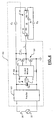
- FIG. 4 is an electrical schematic and functional block diagram of an exemplary implementation of the control system of FIG. 3;
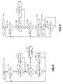
- FIG. 5 is a first exemplary flowchart illustrating steps for operating the control system of FIG. 3;
- FIG. 6 is a second exemplary flowchart illustrating steps for operating the control system of FIG. 3.
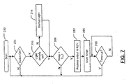
- FIG. 7 is a third exemplary flowchart illustrating steps for operating the control system of FIG. 3.
- module refers to an application specific integrated circuit (ASIC), an electronic circuit, a processor (shared, dedicated, or group) and memory that execute one or more software or firmware programs, a combinational logic circuit, and/or other suitable components that provide the described functionality.
- ASIC application specific integrated circuit
- processor shared, dedicated, or group
- memory that execute one or more software or firmware programs
- combinational logic circuit and/or other suitable components that provide the described functionality.
- a ballast module 100 includes a control module 104, one or more electrolytic capacitors 108, and one or more other components generally identified at 110.
- the ballast module 100 includes one or more temperature sensing modules 112 and 114 that sense operating temperatures of components of the ballast module 100 and/or of the control system of the florescent light 10.
- the temperature sensor 112 senses an operating temperature of the electrolytic capacitor 108 and the temperature sensor 114 senses an operating temperature of one or more other components 110 of the ballast module 100 and/or the control system.
- the control module 104 adjusts operation of the fluorescent light 10 based on one or more of the sensed operating temperatures. For example, the control module 104 shuts off the florescent light 10 when the operating temperature of the electrolytic capacitor 56 exceeds a predetermined temperature threshold. Alternately, the control module 104 turns off the florescent light 10 for a predetermined period, until reset, indefinitely and/or using other criteria. In other implementations, the control module 104 lowers an output voltage and/or current of the ballast module 100 for a predetermined period, indefinitely, until reset and/or using other criteria.
- an exemplary implementation of the ballast module 100 is shown to include a full or half-wave rectifier 120, the electrolytic capacitor 106 and the control module 104.
- a first terminal of a power transistor 126 is connected to a first output of the rectifier 120.
- a second terminal is connected to the control module 104 and to a first terminal of a power transistor 128.
- the control module 104 switches the power transistors on and off to vary current and/or voltage to the florescent light 10 during startup and/or operation.
- a capacitor C1 may be .connected to the first output of the rectifier 120, the second terminal of the power transistor 126, the first terminal of the power transistor 128 and one end of an inductor L. An opposite end of the inductor L may communicate with one end of the electrode 18A. An opposite end of the electrode 18A is coupled by a capacitor C3 to one end of the electrode 18B. The first output of the rectifier 120 is coupled by a capacitor C2 to an opposite end of the electrode 18B.
- step 200 control determines whether the switch 24 is on. If false, control returns to step 204. If step 204 is true, control determines whether the florescent light 10 is already on. If true, control continues with step 208 and determines whether a sensed temperature is greater than a threshold temperature. The sensed temperature may relate to the electrolytic capacitor 56 and/or other components of the ballast module 100 and/or other components of the control system. If step 206 is false, control starts the light in step 214 continues with step 208. If step 208 is false and the threshold temperature has not been exceeded, control determines whether the switch 24 is off in step 210. If the switch 24 is not off, control returns to step 204.
- step 204 control determines whether the switch 24 is on. If false, control returns to step 204.
- control turns off the switch 24 and/or florescent light 10 in step 216.
- the switch 24 may be controlled by the control module 104. Alternately, the control module 104 may turn off the florescent light 10 independent from a position of the switch 24. Alternately, the control module 104 may operate as a three way switch in conjunction with a three-way switch 24.
- step 210 is true and the switch 24 is off, control turns off the florescent light 10 in step 218.
- step 208 When step 208 is false, control returns to step 204.
- step 208 When step 208 is true, control turns off the florescent light 10 in step 242.
- step 246 control starts a timer.
- step 250 control determines whether the timer is up. If step 250 is true, control returns to step 204. Otherwise, control returns to step 250.
- step 208 control reduces power that is output to the florescent light 10 in step 282. Reducing power output to the florescent light 10 may include reducing voltage and/or current output by the ballast module 100. The florescent light 10 may be operated in this mode until reset using the switch 24. Alternately in step 286. control starts a timer. In step 290, control determines whether the timer is up. If step 290 is true, control returns to step 204. Otherwise, control returns to step 290.
- the broad teachings of the present invention can be implemented in a variety of forms.
- the temperature of a component can be sensed and the power output can be modulated accordingly.
- Hysteresis, averaging and/or other techniques can be used to reduce flicker and/or other noticeable changes in light intensity that may occur. Therefore, while this invention has been described in connection with particular examples thereof, the true scope of the invention should not be so limited since other modifications will become apparent to the skilled practitioner upon a study of the drawings, the specification and the following claims.
Landscapes
- Circuit Arrangements For Discharge Lamps (AREA)
Abstract
Description
- The present invention relates to fluorescent light fixtures, and more particularly to control systems for fluorescent light fixtures.
- Referring now to FIG. 1, a
fluorescent lamp 10 includes a sealedglass tube 12 that contains a first material such as mercury and a first inert gas such as argon, which are both generally identified at 14. Thetube 12 is pressurized.Phosphor powder 16 may be coated along an inner surface of thetube 12. Thetube 12 includeselectrodes 18A and 188 (collectively electrodes 18) that are located at opposite ends of thetube 12. Power is supplied to the electrodes 18 by a control system that may include anAC source 22, aswitch 24, aballast module 26 and a capacitor 28. - When the
switch 24 is closed, the control system supplies power to the electrodes 18. Electrons migrate through thegas 14 from one end of thetube 12 to the opposite end. Energy from the flowing electrons changes some of the mercury from a liquid to a gas. As electrons and charged atoms move through thetube 12, some will collide with the gaseous mercury atoms. The collisions excite the atoms and cause electrons to move to a higher state. As the electrons return to a lower energy level they release photons or light. Electrons in mercury atoms release light photons in the ultraviolet wavelength range. Thephosphor coating 16 absorbs the ultraviolet photons, which causes electrons in the phosphor coating 16 to jump to a higher level. When the electrons return to a lower energy level, they release photons having a wavelength corresponding to white light. - To send current through the
tube 12, thefluorescent light 10 needs free electrons and ions and a difference in charge between the electrodes 18. Generally, there are few ions and free electrons in thegas 14 because atoms typically maintain a neutral charge. When thefluorescent light 10 is turned on, it needs to introduce new free electrons and ions. - The
ballast module 26 outputs current through both electrodes 18 during starting. The current flow creates a charge difference between the two electrodes 18. When thefluorescent light 10 is turned on, both electrode filaments heat up very quickly. Electrons are emitted, which ionizes thegas 14 in thetube 12. Once the gas is ionized, the voltage difference between the electrodes 18 establishes an electrical arc. The flowing charged particles excite the mercury atoms, which triggers the illumination process. As more electrons and ions flow through a particular area, they bump into more atoms, which frees up electrons and creates more charged particles. Resistance decreases and current increases. Theballast module 26 regulates power both during and after startup. - Referring now to FIG. 2, some
ballast modules 50 include acontrol module 54, one or moreelectrolytic capacitors 56 and other components 58. Theelectrolytic capacitors 56 may be used to filter or smooth voltage.Electrolytic capacitors 56 and/or other system components may be sensitive to high operating temperatures. If the operating temperature exceeds a threshold for a sufficient period, theelectrolytic capacitor 56 and/or other system components may be damaged and thefluorescent light 10 may become inoperable. - A ballast module for a fluorescent light comprises an electrolytic capacitance element. A temperature sensor senses a temperature of the electrolytic capacitance element. A control module communicates the temperature sensor and adjusts power output to the fluorescent light when the sensed temperature exceeds a predetermined threshold.
- In other features, the control module reduces the power output to the fluorescent light. The control module reduces the power output for a predetermined period. The control module increases power output to the fluorescent light after the predetermined period. The control module turns off the power output to the fluorescent light. The control module turns off the power output for a predetermined period. The control module increases power output to the fluorescent light after the predetermined period. The control module modulates the power output based on the sensed temperature.
- A system comprises the ballast module and further comprises a switch that selectively provides power to the control module. The switch is a three-way switch. A rectifier module has an input that selectively communicates with a voltage source. The electrolytic capacitance element and the control module communicate with an output of the rectifier module.
- In other features, the ballast module further comprises a first power transistor having a first terminal that communicates with a first output terminal of the rectifier and a control terminal that communicates with the control module. A second power transistor has a first terminal that communicates with a second terminal of the first power transistor, and a control terminal that communicates with the control module. A second capacitance element communicates with the first and second terminals of the first power transistor. An inductance element has one end that communicates with the second terminal of the first power transistor and an opposite end that communicates with an electrode of the fluorescent light.
- A system comprises the ballast module and further comprises the fluorescent light having first and second pairs of electrodes. A third capacitance element communicates with one of the first pair of electrodes and one of the second pair of electrodes. A system comprises the ballast module and further comprises the fluorescent light having first and second pairs of electrodes. A fourth capacitance element communicates with one of the first pair of electrodes and the second capacitance element.
- A ballast module for a fluorescent light comprises electrolytic capacitance means for providing capacitance. Temperature sensing means senses a temperature of the electrolytic capacitance means. Control means communicates with the temperature sensing means for adjusting power output to the fluorescent light when the sensed temperature exceeds a predetermined threshold.
- In other features, the control means reduces the power output to the fluorescent light. The control means reduces the power output for a predetermined period. The control means increases power output to the fluorescent light after the predetermined period. The control means turns off the power output to the fluorescent light. The control means turns off the power output for a predetermined period. The control means increases power output to the fluorescent light after the predetermined period. The control means modulates the power output based on the sensed temperature.
- A system comprises the ballast module and further comprises switching means for selectively providing power to the control means. The switching means is a three-way switching means. Rectifier means for rectifying has an input that selectively communicates with a voltage source. The electrolytic capacitance means and the control means communicate with an output of the rectifier means. First power switching means for switching has a first terminal that communicates with a first output terminal of the rectifier and a control terminal that communicates with the control means. Second power switching means for switching has a first terminal that communicates with a second terminal of the first power switching means, and a control terminal that communicates with the control means. Second capacitance means for providing capacitance communicates with the first and second terminals of the first power switching means. Inductance means for providing inductance has one end that communicates with the second terminal of the first power switching means and an opposite end that communicates with an electrode of the fluorescent light.
- A system comprises the ballast module and further comprises the fluorescent light having first and second pairs of electrodes. Third capacitance means for providing capacitance communicates with one of the first pair of electrodes and one of the second pair of electrodes. A system comprises the ballast module and further comprises the fluorescent light having first and second pairs of electrodes. Fourth capacitance means for providing capacitance and that communicates with one of the first pair of electrodes and the second capacitance means.
- A method for operating a ballast module for a fluorescent light comprises providing an electrolytic capacitance element in the ballast module; sensing a temperature of the electrolytic capacitance element; and adjusting power output to the fluorescent light when the sensed temperature exceeds a predetermined threshold.
- In other features, the method includes reducing the power output to the fluorescent light. The method includes reducing the power output for a predetermined period. The method includes increasing power output to the fluorescent light after the predetermined period. The method includes turning off the power output to the fluorescent light. The method includes turning off the power output for a predetermined period. The method includes increasing power output to the fluorescent light after the predetermined period. The method includes modulating the power output based on the sensed temperature. The method includes selectively providing power to the control module.
- A control system for a fluorescent light comprises a first electrical component. A temperature sensor senses a temperature of the first electrical component. A control module communicates with the temperature sensor and adjusts power output to the fluorescent light when the sensed temperature exceeds a predetermined threshold.
- In other features, the control module reduces the power output to the fluorescent light. The control module reduces the power output for a predetermined period. The control module increases power output to the fluorescent light after the predetermined period. The control module turns off the power output to the fluorescent light. The control module turns off the power output for a predetermined period. The control module increases power output to the fluorescent light after the predetermined period. The control module modulates the power output based on the sensed temperature.
- The control system further comprises a switch that selectively provides power to the control module. The switch is a three-way switch. A rectifier module has an input that selectively communicates with a voltage source. The electrolytic capacitance element and the control module communicate with an output of the rectifier module.
- In other features, the control system further comprises a first power transistor having a first terminal that communicates with a first output terminal of the rectifier and a control terminal that communicates with the control module. A second power transistor has a first terminal that communicates with a second terminal of the first power transistor, and a control terminal that communicates with the control module. A second capacitance element communicates with the first and second terminals of the first power transistor. An inductance element has one end that communicates with the second terminal of the first power transistor and an opposite end that communicates with an electrode of the fluorescent light.
- The control system further comprises the fluorescent light having first and second pairs of electrodes. A third capacitance element communicates with one of the first pair of electrodes and one of the second pair of electrodes. The control system further comprises the fluorescent light having first and second pairs of electrodes. A fourth capacitance element communicates with one of the first pair of electrodes and the second capacitance element.
- A control system for a fluorescent light comprises first means for providing a first electrical function. Temperature sensing means senses a temperature of the first means. Control means communicates with the temperature sensing means for adjusting power output to the fluorescent light when the sensed temperature exceeds a predetermined threshold.
- In other features, the control means reduces the power output to the fluorescent light. The control means reduces the power output for a predetermined period. The control means increases power output to the fluorescent light after the predetermined period. The control means turns off the power output to the fluorescent light. The control means turns off the power output for a predetermined period. The control means increases power output to the fluorescent light after the predetermined period. The control means modulates the power output based on the sensed temperature.
- The control system further comprises switching means for selectively providing power to the control means. The switching means is a three-way switching means. Rectifier means for rectifying has an input that selectively communicates with a voltage source. The electrolytic capacitance means and the control means communicate with an output of the rectifier means. First power switching means for switching has a first terminal that communicates with a first output terminal of the rectifier and a control terminal that communicates with the control means. Second power switching means for switching has a first terminal that communicates with a second terminal of the first power switching means, and a control terminal that communicates with the control means. Second capacitance means for providing capacitance communicates with the first and second terminals of the first power switching means. Inductance means for providing inductance has one end that communicates with the second terminal of the first power switching means and an opposite end that communicates with an electrode of the fluorescent light.
- The control system further comprises the fluorescent light having first and second pairs of electrodes. Third capacitance means for providing capacitance communicates with one of the first pair of electrodes and one of the second pair of electrodes. The control system further comprises the fluorescent light having first and second pairs of electrodes. Fourth capacitance means for providing capacitance and that communicates with one of the first pair of electrodes and the second capacitance means.
- A method for operating a control system for a fluorescent light comprises providing a first electrical component; sensing a temperature of the first electrical component; and adjusting power output to the fluorescent light when the sensed temperature exceeds a predetermined threshold.
- In other features, the method includes reducing the power output to the fluorescent light. The method includes reducing the power output for a predetermined period. The method includes increasing power output to the fluorescent light after the predetermined period. The method includes turning off the power output to the fluorescent light. The method includes turning off the power output for a predetermined period. The method includes increasing power output to the fluorescent light after the predetermined period. The method includes modulating the power output based on the sensed temperature. The method includes selectively providing power to the control module.
- Further areas of applicability of the present invention will become apparent from the detailed description provided hereinafter. It should be understood that the detailed description and specific examples, while indicating the preferred embodiment of the invention, are intended for purposes of illustration only and are not intended to limit the scope of the invention.
- The present invention will become more fully understood from the detailed description and the accompanying drawings, wherein:
- FIG. 1 is a functional block diagram of an exemplary control system for a fluorescent light according to the prior art;
- FIG. 2 is a more detailed functional block diagram of the control system for the fluorescent light of FIG. 1;
- FIG. 3 is a functional block diagram of an improved control system for a fluorescent light according to the present invention;
- FIG. 4 is an electrical schematic and functional block diagram of an exemplary implementation of the control system of FIG. 3;
- FIG. 5 is a first exemplary flowchart illustrating steps for operating the control system of FIG. 3;
- FIG. 6 is a second exemplary flowchart illustrating steps for operating the control system of FIG. 3; and
- FIG. 7 is a third exemplary flowchart illustrating steps for operating the control system of FIG. 3.
- The following description of the preferred embodiment(s) is merely exemplary in nature and is in no way intended to limit the invention, its application, or uses. As used herein, the term module refers to an application specific integrated circuit (ASIC), an electronic circuit, a processor (shared, dedicated, or group) and memory that execute one or more software or firmware programs, a combinational logic circuit, and/or other suitable components that provide the described functionality. For purposes of clarity, the same reference numbers will be used in the drawings to identify similar elements.
- Referring now to FIG. 3, a functional block diagram of a
control system 98 for thefluorescent light 10 is shown. Aballast module 100 includes acontrol module 104, one or moreelectrolytic capacitors 108, and one or more other components generally identified at 110. Theballast module 100 includes one or moretemperature sensing modules ballast module 100 and/or of the control system of theflorescent light 10. In some implementations, thetemperature sensor 112 senses an operating temperature of theelectrolytic capacitor 108 and thetemperature sensor 114 senses an operating temperature of one or more other components 110 of theballast module 100 and/or the control system. - The
control module 104 adjusts operation of thefluorescent light 10 based on one or more of the sensed operating temperatures. For example, thecontrol module 104 shuts off theflorescent light 10 when the operating temperature of theelectrolytic capacitor 56 exceeds a predetermined temperature threshold. Alternately, thecontrol module 104 turns off theflorescent light 10 for a predetermined period, until reset, indefinitely and/or using other criteria. In other implementations, thecontrol module 104 lowers an output voltage and/or current of theballast module 100 for a predetermined period, indefinitely, until reset and/or using other criteria. - Referring now to FIG. 4, an exemplary implementation of the
ballast module 100 is shown to include a full or half-wave rectifier 120, theelectrolytic capacitor 106 and thecontrol module 104. A first terminal of apower transistor 126 is connected to a first output of therectifier 120. A second terminal is connected to thecontrol module 104 and to a first terminal of apower transistor 128. Thecontrol module 104 switches the power transistors on and off to vary current and/or voltage to theflorescent light 10 during startup and/or operation. - A capacitor C1 may be .connected to the first output of the
rectifier 120, the second terminal of thepower transistor 126, the first terminal of thepower transistor 128 and one end of an inductor L. An opposite end of the inductor L may communicate with one end of theelectrode 18A. An opposite end of theelectrode 18A is coupled by a capacitor C3 to one end of theelectrode 18B. The first output of therectifier 120 is coupled by a capacitor C2 to an opposite end of theelectrode 18B. - Referring now to FIG. 5, a flowchart illustrating steps for operating the control system of FIG. 3 is shown. Control begins with
step 200. Instep 204, control determines whether theswitch 24 is on. If false, control returns to step 204. Ifstep 204 is true, control determines whether theflorescent light 10 is already on. If true, control continues withstep 208 and determines whether a sensed temperature is greater than a threshold temperature. The sensed temperature may relate to theelectrolytic capacitor 56 and/or other components of theballast module 100 and/or other components of the control system. Ifstep 206 is false, control starts the light instep 214 continues withstep 208. Ifstep 208 is false and the threshold temperature has not been exceeded, control determines whether theswitch 24 is off instep 210. If theswitch 24 is not off, control returns to step 204. - When
step 208 is true, control turns off theswitch 24 and/or florescent light 10 instep 216. In some implementations, theswitch 24 may be controlled by thecontrol module 104. Alternately, thecontrol module 104 may turn off theflorescent light 10 independent from a position of theswitch 24. Alternately, thecontrol module 104 may operate as a three way switch in conjunction with a three-way switch 24. Whenstep 210 is true and theswitch 24 is off, control turns off theflorescent light 10 instep 218. - Referring now to FIG. 6, a flowchart illustrating alternate steps for operating the control system of FIG. 3 is shown. When
step 208 is false, control returns to step 204. Whenstep 208 is true, control turns off theflorescent light 10 instep 242. Instep 246, control starts a timer. Instep 250, control determines whether the timer is up. Ifstep 250 is true, control returns to step 204. Otherwise, control returns to step 250. - Referring now to FIG. 7, a flowchart illustrating alternative steps for operating the control system of FIG. 3 is shown. When
step 208 is true, control reduces power that is output to theflorescent light 10 instep 282. Reducing power output to theflorescent light 10 may include reducing voltage and/or current output by theballast module 100. Theflorescent light 10 may be operated in this mode until reset using theswitch 24. Alternately instep 286. control starts a timer. Instep 290, control determines whether the timer is up. Ifstep 290 is true, control returns to step 204. Otherwise, control returns to step 290. - Those skilled in the art can now appreciate from the foregoing description that the broad teachings of the present invention can be implemented in a variety of forms. For example, the temperature of a component can be sensed and the power output can be modulated accordingly. Hysteresis, averaging and/or other techniques can be used to reduce flicker and/or other noticeable changes in light intensity that may occur. Therefore, while this invention has been described in connection with particular examples thereof, the true scope of the invention should not be so limited since other modifications will become apparent to the skilled practitioner upon a study of the drawings, the specification and the following claims.
Claims (16)
- A ballast module for a fluorescent light, comprising:an electrolytic capacitance element;a temperature sensor that senses a temperature of said electrolytic capacitance element; anda control module that communicates said temperature sensor and that adjusts power output to the fluorescent light when said sensed temperature exceeds a predetermined threshold.
- The ballast module of Claim 1 wherein said control module reduces said power output to the fluorescent light.
- The ballast module of Claim 1 wherein said control module reduces said power output for a predetermined period.
- The ballast module of Claim 3 wherein said control module increases power output to the fluorescent light after said predetermined period.
- The ballast module of Claim 1 wherein said control module turns off said power output to the fluorescent light.
- The ballast module of Claim 1 wherein said control module turns off said power output for a predetermined period.
- The ballast module of Claim 6 wherein said control module increases power output to the fluorescent light after said predetermined period.
- The ballast module of Claim 1 wherein said control module modulates said power output based on said sensed temperature.
- A system comprising the ballast module of Claim 1 and further comprising a switch that selectively provides power to said control module.
- The system of Claim 9 wherein said switch is a three-way switch.
- The ballast module of Claim 1 further comprising a rectifier module having an input that selectively communicates with a voltage source, wherein said electrolytic capacitance element and said control module communicate with an output of said rectifier module.
- The ballast module of Claim 11 further comprising:a first power transistor having a first terminal that communicates with a first output terminal of said rectifier and a control terminal that communicates with said control module; anda second power transistor having a first terminal that communicates with a second terminal of said first power transistor, and a control terminal that communicates with said control module.
- The ballast module of Claim 12 further comprising a second capacitance element that communicates with said first and second terminals of said first power transistor.
- The ballast module of Claim 13 further comprising an inductance element having one end that communicates with said second terminal of said first power transistor and an opposite end that communicates with an electrode of the fluorescent light.
- A system comprising the ballast module of Claim 1 and further comprising:the fluorescent light having first and second pairs of electrodes; anda third capacitance element that communicates with one of said first pair of electrodes and one of said second pair of electrodes.
- A system comprising the ballast module of Claim 13 and further comprising:the fluorescent light having first and second pairs of electrodes; anda fourth capacitance element that communicates with one of said first pair of electrodes and said second capacitance element.
Applications Claiming Priority (2)
| Application Number | Priority Date | Filing Date | Title |
|---|---|---|---|
| US67225005P | 2005-04-18 | 2005-04-18 | |
| US11/112,808 US7560866B2 (en) | 2005-04-18 | 2005-04-22 | Control system for fluorescent light fixture |
Publications (2)
| Publication Number | Publication Date |
|---|---|
| EP1718133A1 true EP1718133A1 (en) | 2006-11-02 |
| EP1718133B1 EP1718133B1 (en) | 2008-10-08 |
Family
ID=36917318
Family Applications (1)
| Application Number | Title | Priority Date | Filing Date |
|---|---|---|---|
| EP06006307A Expired - Lifetime EP1718133B1 (en) | 2005-04-18 | 2006-03-27 | Improved control system for fluorescent light fixture |
Country Status (6)
| Country | Link |
|---|---|
| US (3) | US7560866B2 (en) |
| EP (1) | EP1718133B1 (en) |
| JP (2) | JP5204379B2 (en) |
| DE (1) | DE602006003011D1 (en) |
| SG (1) | SG126839A1 (en) |
| TW (1) | TWI426827B (en) |
Cited By (1)
| Publication number | Priority date | Publication date | Assignee | Title |
|---|---|---|---|---|
| GB2469810A (en) * | 2009-04-28 | 2010-11-03 | Kaoyi Electronic Co Ltd | A fluorescent lamp with overheat protection function to cut-off power |
Families Citing this family (4)
| Publication number | Priority date | Publication date | Assignee | Title |
|---|---|---|---|---|
| US7560866B2 (en) * | 2005-04-18 | 2009-07-14 | Marvell World Trade Ltd. | Control system for fluorescent light fixture |
| US7619447B2 (en) * | 2005-09-27 | 2009-11-17 | Marvell World Trade Ltd. | High voltage high side transistor driver |
| US20130156204A1 (en) * | 2011-12-14 | 2013-06-20 | Mitel Networks Corporation | Visual feedback of audio input levels |
| CN115855303B (en) * | 2022-11-30 | 2025-08-15 | 西北核技术研究所 | Film type heat flow sensor based on double-color thermosensitive phosphorescence coating temperature measurement |
Citations (4)
| Publication number | Priority date | Publication date | Assignee | Title |
|---|---|---|---|---|
| WO1988001467A1 (en) * | 1986-08-15 | 1988-02-25 | Mound Holdings Limited | Fluorescent lamp operation |
| US20020101185A1 (en) * | 2000-10-12 | 2002-08-01 | Henry Kozlowski | Discharge lamps |
| US6453145B1 (en) * | 1999-11-16 | 2002-09-17 | Minolta Co., Ltd. | Flash-based fixing apparatus with flash lamp of stable illumination for electrographic image forming apparatus |
| EP1338874A1 (en) * | 2002-02-21 | 2003-08-27 | Omron Corporation | Remaining lifetime estimating method, temperature detection structure and electronic equipment |
Family Cites Families (53)
| Publication number | Priority date | Publication date | Assignee | Title |
|---|---|---|---|---|
| US3587061A (en) * | 1968-09-24 | 1971-06-22 | Automatic Elect Lab | Time-shaped lamp control apparatus employing lamp filament resistance as an integral status memory |
| US3978368A (en) * | 1973-02-21 | 1976-08-31 | Hitachi, Ltd. | Discharge lamp control circuit |
| WO1988010467A1 (en) | 1987-06-19 | 1988-12-29 | Lucero, James, L. | Drive-through credit card payment device |
| CA2015281C (en) * | 1989-04-25 | 1995-08-29 | Minoru Maehara | Polarized electromagnetic relay |
| US5003230A (en) * | 1989-05-26 | 1991-03-26 | North American Philips Corporation | Fluorescent lamp controllers with dimming control |
| JPH04126349A (en) * | 1990-09-18 | 1992-04-27 | Toshiba Lighting & Technol Corp | Discharge lamp device |
| US5402303A (en) * | 1991-04-18 | 1995-03-28 | Luck; Jonathan M. | Remotely-powdered and remotely-addressed zero-standby-current energy-accumulating high-power solenoid drivers, particularly for systems that are micropowered |
| US5309066A (en) * | 1992-05-29 | 1994-05-03 | Jorck & Larsen A/S | Solid state ballast for fluorescent lamps |
| US5357170A (en) * | 1993-02-12 | 1994-10-18 | Lutron Electronics Co., Inc. | Lighting control system with priority override |
| ES2122144T3 (en) * | 1993-04-23 | 1998-12-16 | Koninkl Philips Electronics Nv | POWER FACTOR CORRECTOR CIRCUIT. |
| KR0155936B1 (en) * | 1995-12-26 | 1998-12-15 | 손욱 | Fluorescent lamp ballast circuit |
| FR2749121B1 (en) * | 1996-05-24 | 1998-06-19 | Alcatel Mobile Comm France | MAN-MACHINE INTERFACE DEVICE FOR TELEPHONE TERMINAL |
| US5744912A (en) * | 1996-06-26 | 1998-04-28 | So; Gin Pang | Electronic ballast having an oscillator shutdown circuit for single or multiple fluorescent tubes for lamps |
| US5798614A (en) * | 1996-09-26 | 1998-08-25 | Rockwell International Corp. | Fluorescent lamp filament drive technique |
| KR100355728B1 (en) * | 1997-01-07 | 2002-11-18 | 샤프 가부시키가이샤 | Illumination device, method for driving the illumination device and display device including the illumination device |
| EP0889675A1 (en) * | 1997-07-02 | 1999-01-07 | MAGNETEK S.p.A. | Electronic ballast with lamp tyre recognition |
| FR2771590B1 (en) * | 1997-11-21 | 2003-01-03 | Sgs Thomson Microelectronics | FLUORESCENT LAMP CONTROL CIRCUIT |
| EP0945710B2 (en) * | 1998-03-21 | 2009-10-28 | Continental Automotive GmbH | Indicating instrument |
| US6140751A (en) * | 1998-03-30 | 2000-10-31 | General Electric Company | Electrolytic capacitor heat sink |
| US5973455A (en) * | 1998-05-15 | 1999-10-26 | Energy Savings, Inc. | Electronic ballast with filament cut-out |
| US5959525A (en) * | 1998-08-13 | 1999-09-28 | Cts Corporation | Variable resistance slide control device with a switch |
| DE19850441A1 (en) * | 1998-10-27 | 2000-05-11 | Trilux Lenze Gmbh & Co Kg | Method and ballast for operating a lamp provided with a fluorescent lamp |
| US6285138B1 (en) * | 1998-12-09 | 2001-09-04 | Matsushita Electric Industrial Co., Ltd. | Apparatus for lighting fluorescent lamp |
| JP3315385B2 (en) * | 1998-12-09 | 2002-08-19 | 松下電器産業株式会社 | Fluorescent lamp lighting device |
| US6191539B1 (en) * | 1999-03-26 | 2001-02-20 | Korry Electronics Co | Fluorescent lamp with integral conductive traces for extending low-end luminance and heating the lamp tube |
| DE19923945A1 (en) * | 1999-05-25 | 2000-12-28 | Tridonic Bauelemente | Electronic ballast for at least one low-pressure discharge lamp |
| US6140772A (en) * | 1999-07-26 | 2000-10-31 | Rockwell Collins, Inc. | Method and apparatus for control of fluorescent lamps |
| US6424100B1 (en) * | 1999-10-21 | 2002-07-23 | Matsushita Electric Industrial Co., Ltd. | Fluorescent lamp operating apparatus and compact self-ballasted fluorescent lamp |
| DE19963292A1 (en) * | 1999-12-27 | 2001-06-28 | Tridonic Bauelemente | Electronic voltage adapter has variable output frequency converter supplied with direct voltage and operated at frequencies above 1 MHz for ignition and during operation |
| CN1443306A (en) * | 2000-06-02 | 2003-09-17 | 奥斯泰科仪器有限公司 | Filament Controller |
| US6300728B1 (en) * | 2000-06-16 | 2001-10-09 | Bgm Engineering, Inc. | Method and apparatus for powering fluorescent lighting |
| TW458485U (en) * | 2000-07-31 | 2001-10-01 | Nat Science Council | Pre-heat circuit of gas discharging lamp |
| US6376999B1 (en) * | 2000-09-15 | 2002-04-23 | Philips Electronics North America Corporation | Electronic ballast employing a startup transient voltage suppression circuit |
| IT1318952B1 (en) * | 2000-10-02 | 2003-09-19 | St Microelectronics Srl | HIGH CURRENT PROTECTION CIRCUIT IN PERILLUMINATION CONVERTERS |
| US6710993B1 (en) * | 2000-11-27 | 2004-03-23 | Koninklijke Philips Electronics N.V. | Method and apparatus for providing overload protection for a circuit |
| DE10106438A1 (en) * | 2001-02-09 | 2002-08-14 | Patent Treuhand Ges Fuer Elektrische Gluehlampen Mbh | Ballast for operating electric lamps |
| JP3942387B2 (en) * | 2001-02-13 | 2007-07-11 | 株式会社小糸製作所 | Discharge lamp lighting circuit |
| WO2002098186A1 (en) * | 2001-05-25 | 2002-12-05 | Matsushita Electric Works, Ltd. | Electronic ballast for a high intensity discharge lamp |
| JP2003264093A (en) * | 2002-01-07 | 2003-09-19 | Mitsubishi Electric Corp | High pressure discharge lamp lighting device |
| US6781328B2 (en) * | 2002-01-15 | 2004-08-24 | Matsushita Electric Industrial Co., Ltd. | Image display apparatus and method for operating the same and lamp unit for image display apparatus |
| CN1579115A (en) * | 2002-02-20 | 2005-02-09 | 松下电器产业株式会社 | Electrodeless discharge lamp lighting device, light bulb type electrodeless fluorescent lamp and discharge lamp lighting device |
| US6713966B2 (en) * | 2002-05-21 | 2004-03-30 | Yazaki North America, Inc. | Event and arc detection in lamps |
| HK1051122A2 (en) * | 2002-05-24 | 2003-06-27 | Clipsal Asia Holdings Limited | A dimming apparatus especially a dimmer for a compact fluorescent lamp |
| US6940733B2 (en) * | 2002-08-22 | 2005-09-06 | Supertex, Inc. | Optimal control of wide conversion ratio switching converters |
| KR100493170B1 (en) | 2003-02-06 | 2005-06-02 | 삼성전자주식회사 | Context-based telecommunication method and mobile telecommunication system therefor |
| US7126288B2 (en) * | 2003-05-05 | 2006-10-24 | International Rectifier Corporation | Digital electronic ballast control apparatus and method |
| JP2004342321A (en) * | 2003-05-12 | 2004-12-02 | Matsushita Electric Works Ltd | Discharge lamp lighting device |
| WO2005006820A1 (en) | 2003-06-13 | 2005-01-20 | Ictel, Llc | Electronic ballast |
| TWM255612U (en) * | 2004-03-25 | 2005-01-11 | Fu-Hua Miau | Metal composite lamp control device with low current for remotely starting |
| TWM257075U (en) * | 2004-04-29 | 2005-02-11 | Ligtek Electronics Co Ltd | Three-stage electronic ballast for metal halide lamps |
| US7145342B2 (en) * | 2004-07-07 | 2006-12-05 | Access Business Group International Llc | System and method for automated filament testing of gas discharge lamps |
| US7560866B2 (en) * | 2005-04-18 | 2009-07-14 | Marvell World Trade Ltd. | Control system for fluorescent light fixture |
| US7414369B2 (en) * | 2005-04-18 | 2008-08-19 | Marvell World Trade Ltd. | Control system for fluorescent light fixture |
-
2005
- 2005-04-22 US US11/112,808 patent/US7560866B2/en not_active Expired - Fee Related
-
2006
- 2006-03-22 SG SG200601868A patent/SG126839A1/en unknown
- 2006-03-27 EP EP06006307A patent/EP1718133B1/en not_active Expired - Lifetime
- 2006-03-27 DE DE602006003011T patent/DE602006003011D1/en not_active Expired - Lifetime
- 2006-03-31 JP JP2006099049A patent/JP5204379B2/en not_active Expired - Fee Related
- 2006-03-31 TW TW095111643A patent/TWI426827B/en not_active IP Right Cessation
-
2009
- 2009-07-14 US US12/502,570 patent/US8120286B2/en not_active Expired - Fee Related
-
2012
- 2012-02-20 US US13/400,269 patent/US8531107B2/en not_active Expired - Fee Related
- 2012-02-27 JP JP2012040573A patent/JP5379875B2/en not_active Expired - Fee Related
Patent Citations (4)
| Publication number | Priority date | Publication date | Assignee | Title |
|---|---|---|---|---|
| WO1988001467A1 (en) * | 1986-08-15 | 1988-02-25 | Mound Holdings Limited | Fluorescent lamp operation |
| US6453145B1 (en) * | 1999-11-16 | 2002-09-17 | Minolta Co., Ltd. | Flash-based fixing apparatus with flash lamp of stable illumination for electrographic image forming apparatus |
| US20020101185A1 (en) * | 2000-10-12 | 2002-08-01 | Henry Kozlowski | Discharge lamps |
| EP1338874A1 (en) * | 2002-02-21 | 2003-08-27 | Omron Corporation | Remaining lifetime estimating method, temperature detection structure and electronic equipment |
Cited By (1)
| Publication number | Priority date | Publication date | Assignee | Title |
|---|---|---|---|---|
| GB2469810A (en) * | 2009-04-28 | 2010-11-03 | Kaoyi Electronic Co Ltd | A fluorescent lamp with overheat protection function to cut-off power |
Also Published As
| Publication number | Publication date |
|---|---|
| US7560866B2 (en) | 2009-07-14 |
| JP5204379B2 (en) | 2013-06-05 |
| EP1718133B1 (en) | 2008-10-08 |
| US20060238145A1 (en) | 2006-10-26 |
| US8120286B2 (en) | 2012-02-21 |
| JP5379875B2 (en) | 2013-12-25 |
| TW200701840A (en) | 2007-01-01 |
| JP2012124180A (en) | 2012-06-28 |
| TWI426827B (en) | 2014-02-11 |
| US20120146551A1 (en) | 2012-06-14 |
| JP2006302883A (en) | 2006-11-02 |
| DE602006003011D1 (en) | 2008-11-20 |
| US20090273305A1 (en) | 2009-11-05 |
| US8531107B2 (en) | 2013-09-10 |
| SG126839A1 (en) | 2006-11-29 |
Similar Documents
| Publication | Publication Date | Title |
|---|---|---|
| US6501235B2 (en) | Microcontrolled ballast compatible with different types of gas discharge lamps and associated methods | |
| US8531107B2 (en) | Control system for fluorescent light fixture | |
| JP2008507821A (en) | Control unit for a lamp driver providing a smooth transition between operating modes | |
| US7365498B2 (en) | Electrodeless discharge lamp lighting device and luminaire | |
| JP4506073B2 (en) | Discharge lamp lighting device and lighting device | |
| CN1856205B (en) | Improved control system for fluorescent light fixture | |
| US8164269B2 (en) | Discharge lamp lighting device and lighting fixture | |
| JP4513152B2 (en) | Discharge lamp lighting device | |
| EP1720382B1 (en) | Improved control system for fluorescent light fixture | |
| US20140015416A1 (en) | Lamp driving module | |
| HK1097160A (en) | Improved control system for fluorescent light fixture | |
| EP1314338B1 (en) | Circuit device | |
| KR100505756B1 (en) | Instantaneous electornic ballast stabilizer of Metal Halide Discharge Lamp having takeover current circuit | |
| JP3763837B2 (en) | Fluorescent lamp lighting device | |
| JP3893782B2 (en) | Lighting device | |
| JP4703626B2 (en) | Discharge lamp lighting device | |
| KR200320775Y1 (en) | Instantaneous electornic ballast stabilizer of Metal Halide Discharge Lamp having takeover current circuit | |
| HK1097159A (en) | Improved control system for fluorescent light fixture | |
| JP2006114355A (en) | Electrodeless discharge lamp lighting device and luminaire | |
| JPH08203683A (en) | Electrodeless discharge lamp lighting device | |
| JPH04154088A (en) | Discharge lamp lighting device | |
| JP2011034720A (en) | Discharge lamp lighting device and lighting system |
Legal Events
| Date | Code | Title | Description |
|---|---|---|---|
| PUAI | Public reference made under article 153(3) epc to a published international application that has entered the european phase |
Free format text: ORIGINAL CODE: 0009012 |
|
| AK | Designated contracting states |
Kind code of ref document: A1 Designated state(s): AT BE BG CH CY CZ DE DK EE ES FI FR GB GR HU IE IS IT LI LT LU LV MC NL PL PT RO SE SI SK TR |
|
| AX | Request for extension of the european patent |
Extension state: AL BA HR MK YU |
|
| 17P | Request for examination filed |
Effective date: 20070412 |
|
| 17Q | First examination report despatched |
Effective date: 20070521 |
|
| AKX | Designation fees paid |
Designated state(s): DE FR GB |
|
| GRAP | Despatch of communication of intention to grant a patent |
Free format text: ORIGINAL CODE: EPIDOSNIGR1 |
|
| GRAS | Grant fee paid |
Free format text: ORIGINAL CODE: EPIDOSNIGR3 |
|
| GRAA | (expected) grant |
Free format text: ORIGINAL CODE: 0009210 |
|
| AK | Designated contracting states |
Kind code of ref document: B1 Designated state(s): DE FR GB |
|
| REG | Reference to a national code |
Ref country code: GB Ref legal event code: FG4D |
|
| REF | Corresponds to: |
Ref document number: 602006003011 Country of ref document: DE Date of ref document: 20081120 Kind code of ref document: P |
|
| PLBE | No opposition filed within time limit |
Free format text: ORIGINAL CODE: 0009261 |
|
| STAA | Information on the status of an ep patent application or granted ep patent |
Free format text: STATUS: NO OPPOSITION FILED WITHIN TIME LIMIT |
|
| 26N | No opposition filed |
Effective date: 20090709 |
|
| REG | Reference to a national code |
Ref country code: FR Ref legal event code: PLFP Year of fee payment: 11 |
|
| PGFP | Annual fee paid to national office [announced via postgrant information from national office to epo] |
Ref country code: GB Payment date: 20160329 Year of fee payment: 11 Ref country code: FR Payment date: 20160328 Year of fee payment: 11 |
|
| PGFP | Annual fee paid to national office [announced via postgrant information from national office to epo] |
Ref country code: DE Payment date: 20160331 Year of fee payment: 11 |
|
| REG | Reference to a national code |
Ref country code: DE Ref legal event code: R119 Ref document number: 602006003011 Country of ref document: DE |
|
| GBPC | Gb: european patent ceased through non-payment of renewal fee |
Effective date: 20170327 |
|
| REG | Reference to a national code |
Ref country code: FR Ref legal event code: ST Effective date: 20171130 |
|
| PG25 | Lapsed in a contracting state [announced via postgrant information from national office to epo] |
Ref country code: DE Free format text: LAPSE BECAUSE OF NON-PAYMENT OF DUE FEES Effective date: 20171003 Ref country code: FR Free format text: LAPSE BECAUSE OF NON-PAYMENT OF DUE FEES Effective date: 20170331 |
|
| PG25 | Lapsed in a contracting state [announced via postgrant information from national office to epo] |
Ref country code: GB Free format text: LAPSE BECAUSE OF NON-PAYMENT OF DUE FEES Effective date: 20170327 |