EP1717474A1 - Brake device and hoist for elevator - Google Patents
Brake device and hoist for elevator Download PDFInfo
- Publication number
- EP1717474A1 EP1717474A1 EP04712688A EP04712688A EP1717474A1 EP 1717474 A1 EP1717474 A1 EP 1717474A1 EP 04712688 A EP04712688 A EP 04712688A EP 04712688 A EP04712688 A EP 04712688A EP 1717474 A1 EP1717474 A1 EP 1717474A1
- Authority
- EP
- European Patent Office
- Prior art keywords
- brake
- brake device
- main body
- rotary member
- hoisting machine
- Prior art date
- Legal status (The legal status is an assumption and is not a legal conclusion. Google has not performed a legal analysis and makes no representation as to the accuracy of the status listed.)
- Granted
Links
Images





Classifications
-
- F—MECHANICAL ENGINEERING; LIGHTING; HEATING; WEAPONS; BLASTING
- F16—ENGINEERING ELEMENTS AND UNITS; GENERAL MEASURES FOR PRODUCING AND MAINTAINING EFFECTIVE FUNCTIONING OF MACHINES OR INSTALLATIONS; THERMAL INSULATION IN GENERAL
- F16D—COUPLINGS FOR TRANSMITTING ROTATION; CLUTCHES; BRAKES
- F16D59/00—Self-acting brakes, e.g. coming into operation at a predetermined speed
- F16D59/02—Self-acting brakes, e.g. coming into operation at a predetermined speed spring-loaded and adapted to be released by mechanical, fluid, or electromagnetic means
-
- B—PERFORMING OPERATIONS; TRANSPORTING
- B66—HOISTING; LIFTING; HAULING
- B66D—CAPSTANS; WINCHES; TACKLES, e.g. PULLEY BLOCKS; HOISTS
- B66D5/00—Braking or detent devices characterised by application to lifting or hoisting gear, e.g. for controlling the lowering of loads
- B66D5/02—Crane, lift hoist, or winch brakes operating on drums, barrels, or ropes
- B66D5/12—Crane, lift hoist, or winch brakes operating on drums, barrels, or ropes with axial effect
- B66D5/14—Crane, lift hoist, or winch brakes operating on drums, barrels, or ropes with axial effect embodying discs
-
- B—PERFORMING OPERATIONS; TRANSPORTING
- B66—HOISTING; LIFTING; HAULING
- B66D—CAPSTANS; WINCHES; TACKLES, e.g. PULLEY BLOCKS; HOISTS
- B66D5/00—Braking or detent devices characterised by application to lifting or hoisting gear, e.g. for controlling the lowering of loads
- B66D5/02—Crane, lift hoist, or winch brakes operating on drums, barrels, or ropes
- B66D5/24—Operating devices
- B66D5/30—Operating devices electrical
-
- F—MECHANICAL ENGINEERING; LIGHTING; HEATING; WEAPONS; BLASTING
- F16—ENGINEERING ELEMENTS AND UNITS; GENERAL MEASURES FOR PRODUCING AND MAINTAINING EFFECTIVE FUNCTIONING OF MACHINES OR INSTALLATIONS; THERMAL INSULATION IN GENERAL
- F16D—COUPLINGS FOR TRANSMITTING ROTATION; CLUTCHES; BRAKES
- F16D55/00—Brakes with substantially-radial braking surfaces pressed together in axial direction, e.g. disc brakes
- F16D2055/0075—Constructional features of axially engaged brakes
- F16D2055/0091—Plural actuators arranged side by side on the same side of the rotor
-
- F—MECHANICAL ENGINEERING; LIGHTING; HEATING; WEAPONS; BLASTING
- F16—ENGINEERING ELEMENTS AND UNITS; GENERAL MEASURES FOR PRODUCING AND MAINTAINING EFFECTIVE FUNCTIONING OF MACHINES OR INSTALLATIONS; THERMAL INSULATION IN GENERAL
- F16D—COUPLINGS FOR TRANSMITTING ROTATION; CLUTCHES; BRAKES
- F16D2121/00—Type of actuator operation force
- F16D2121/14—Mechanical
-
- F—MECHANICAL ENGINEERING; LIGHTING; HEATING; WEAPONS; BLASTING
- F16—ENGINEERING ELEMENTS AND UNITS; GENERAL MEASURES FOR PRODUCING AND MAINTAINING EFFECTIVE FUNCTIONING OF MACHINES OR INSTALLATIONS; THERMAL INSULATION IN GENERAL
- F16D—COUPLINGS FOR TRANSMITTING ROTATION; CLUTCHES; BRAKES
- F16D2121/00—Type of actuator operation force
- F16D2121/18—Electric or magnetic
- F16D2121/20—Electric or magnetic using electromagnets
- F16D2121/22—Electric or magnetic using electromagnets for releasing a normally applied brake
Definitions
- the present invention relates to a brake device provided in, for example, an elevator hoisting machine or the like, and to an elevator hoisting machine.
- JP 11-49460 A Disclosed in JP 11-49460 A , for example, is a conventional brake device with which a brake disc rotated integrally with a rotary shaft of an elevator hoisting machine is sandwiched between a pair of brake shoes to thereby brake the rotation of the brake disk and the rotary shaft.
- the elevator hoisting machine is arranged within a narrow space at the bottom or top portion of a hoistway, with the result that the brake device is often arranged at a position not readily accessible to a worker, leading to a reduction in the work efficiency of maintenance and inspection work.
- the present invention has been made to overcome the problem as described above, and therefore it is an object of the present invention to provide a brake device capable of improving the work efficiency of maintenance and inspection work.
- a brake device for braking rotation of a rotary member that is rotatably supported to a support portion comprising: a brake mounting member that is rotatable about a rotation center of the rotary member; a fixing member for fixing the brake mounting member to the support portion and regulating rotation of the brake mounting member; and a brake device main body mounted to the brake mounting member and adapted to brake the rotation of the rotary member.
- an elevator hoisting machine comprising: a hoisting machine main body including a motor portion; a rotary member including a drive sheave and rotated by a drive force of the motor portion; a brake device having a brake device main body, the brake device main body being capable of rotational displacement about a rotation center of the rotary member with respect to the hoisting machine main body and adapted to brake rotation of the rotary member; and a fixing member for regulating the rotational displacement of the brake device main body with respect to the hoisting machine main body.
- Fig. 1 is a schematic side view showing an elevator apparatus (machine room-less elevator apparatus) according to Embodiment 1 of the present invention.
- an elevator hoisting machine 2 is provided at a bottom portion (pit) of the hoistway 1.
- a car 3 and a counterweight 4 are raised and lowered in the hoistway 1 by the drive force of the elevator hoisting machine 2.
- a pair of car suspension sheaves 5a, 5b are provided under the car 3 .
- a counterweight suspension sheave 6 is provided above the counterweight 4.
- a car-side return pulley 7 is provided at a top portion of the hoistway 1 .
- the car 3 and the counterweight 4 are suspended in the hoistway 1 by a plurality of main ropes 9 (of which only one is shown in the figure).
- a rope-end connecting portion 10 is fixed to a top portion of the hoistway 1.
- Each main rope 9 has a first end portion 9a connected to the rope-end connecting portion 10, and a second end portion (not shown).
- the elevator hoisting machine 2 has a drive sheave 11 around which the main ropes 9 are wound.
- the main ropes 9 are wound around the car suspension sheave 5b, the car suspension sheave 5a, the car-side return pulley 7, the drive sheave 11, the counterweight-side return pulley 8a, the counterweight-side return pulley 8b, and the counterweight suspension sheave 6 in the stated order from the first end portion 9a side. That is, the car 3 and the counterweight 4 are suspended by the main ropes 9 according to a 2: 1 roping system.
- Fig. 2 is a side view showing the elevator hoisting machine of Fig. 1.
- the elevator hoisting machine 2 is arranged such that the rotary shaft of the drive sheave 11 becomes horizontal.
- a motor portion 13 and a bearing stand 14 that serves as a support portion are fixed to a base 12 fixed on the floor surface at the bottom portion of the hoistway 1.
- a hoisting machine main body 15 has the base 12, the motor portion 13, and the bearing stand 14.
- the drive sheave 11 is fixed to a main shaft 16.
- a rotary member 17 having the drive sheave 11 and the main shaft 16 is rotatably supported by the motor portion 13 and the bearing stand 14. Further, the rotary member 17 is rotated by the drive force of the motor portion 13 about the axis of the main shaft 16 as the rotation center.
- the brake device 18 for braking the rotation of the rotary member 17.
- the brake device 18 has a brake disc 19 fixed to the main shaft 16 and rotating integrally with the main shaft 16, a brake mounting member 20 mounted to the bearing stand 14, and a brake device main body 21 mounted to the brake mounting member 20 and adapted to brake the rotation of the rotary member 17 through the intermediation of the brake disc 19.
- the brake device main body 21 has a plurality of (in this example, two) brake units 22 that are arranged symmetrical to each other about the rotation center of the rotary member 17.
- Each brake unit 22 is mounted to the brake mounting member 20 through the intermediation of a bracket 23.
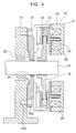
- Fig. 3 is a sectional view showing the brake device 18 of Fig. 2
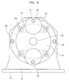
- Fig. 4 is a front view showing the brake device 18 of Fig. 2.
- Each brake unit 22 has a pair of brake pads 24 sandwiching the brake disc 19 therebetween, a brake spring 25 urging the brake pads 24 into contact with the brake disc 19, and an electromagnet 26 for separating the brake pads 24 away from the brake disk 19 against the brake spring 25.
- the main shaft 16 is rotatably supported by the bearing stand 14 through the intermediation of a main shaft bearing 27.
- the brake mounting member 20 is rotatable relative to the bearing stand 14 about the rotation center of the rotary member 17.
- An auxiliary bearing 28 is provided between the brake mounting member 20 and the main shaft 16. Rolling bearings are used as the main shaft bearing 27 and the auxiliary bearing 28.
- the rotation of the brake mounting member 20 with respect to the brake mounting member 20 is regulated by a plurality of fixing bolts 29 serving as fixing members. That is, the brake mounting member 20 is fixed to the bearing stand 14 with the fixing bolts 29.
- the fixing bolts 29 penetrate the brake mounting member 20 for threaded attachment onto the bearing stand 14.
- the brake mounting member 20 is provided with a plurality of through-holes 20a through which the fixing bolts 29 are passed.
- the bearing stand 14 is provided with a plurality of threaded holes 14a allowing threaded attachment of the fixing bolts 29.
- Fig. 5 is a sectional view showing a state in which the fixing bolts 29 of Fig. 3 are removed
- Fig. 6 is a front view showing a state in which the brake device main body 21 of Fig. 4 undergoes rotational displacement.
- the brake mounting member 20 is provided with the through-holes 20a whose number is larger than that of the threaded holes 14a.
- the through-holes 20a are arranged at equal angular pitches around the rotation center of the rotary member 17.
- Fig. 7 is a front view showing how maintenance and inspection work is performed on the brake device 18 of Fig. 2.
- the brake unit 22 is arranged on the floor surface or at a position near the hoistway wall, with the result that it is often impossible to secure a sufficient space for maintenance and inspection work around the brake unit 22.
- the fixing bolts 29 are detached to allow the brake mounting member 20 to rotate, thereby rotationally displacing the position of the brake unit 22.
- the brake unit 22 can be displaced to a position where maintenance and inspection work can be readily performed. Therefore, an improvement can be achieved in terms of the work efficiency of the maintenance and inspection work.
- Fig. 8 is a schematic sectional view showing an elevator apparatus (machine room-less elevator apparatus) according to Embodiment 2 of the present invention.
- the elevator hoisting machine 2 is provided at an upper portion (top portion) of the hoistway 1.
- the elevator hoisting machine 2 is supported by a support beam 31.
- the main ropes 9 are wound around the car suspension sheave 5a, the car suspension sheave 5b, the drive sheave 11, and the counterweight suspension sheave 6 in the stated order from the first end portion 9a side.
- Embodiment 2 is of the same construction as Embodiment 1.
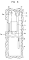
- Fig. 9 is a front view showing how maintenance and inspection work is performed on the brake device 18 of Fig. 8.
- the maintenance and inspection work on the brake unit 22 is performed, for example, from the top of the car 3.
- the other brake unit 22 is arranged at a position far from the car 3. This makes it difficult to perform maintenance and inspection work on the other brake unit 22.
- the fixing bolts 29 are detached to allow the brake mounting member 20 to rotate, thereby rotationally displacing the position of the brake unit 22.
- the brake unit 22 can be displaced to a position where maintenance and inspection work can be readily performed. Therefore, an improvement can be achieved in terms of the work efficiency of the maintenance and inspection work.
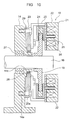
- Fig. 10 is a sectional view of a brake device according to Embodiment 3 of the present invention.
- the bearing stand 14 is provided with a cylindrical bearing support portion 14b that axially protrudes.
- the bearing support portion 14b surrounds the main shaft 16.
- the auxiliary bearing 28 intervenes between the outer peripheral surface of the bearing support portion 14b and the brake mounting member 20.
- Embodiment 3 is of the same construction as Embodiment 1.
- the auxiliary bearing 28 may be provided between the bearing stand 14 and the brake mounting member 20, instead of between the main shaft 16 and the brake mounting member 20.
- the fixing members be arranged at equal angular pitches with respect to the rotation center of the rotary member, they may not be arranged, for example, at a position that cannot be accessed from the top of the car 3 as seen in Fig. 8. Accordingly, there is also no particular limitation as to the number of the fixing members.
- the brake device main body 21 brakes the rotation of the brake disc 19 at two circumferential locations of the brake disc 19, such braking may be effected at one or three or more locations.
- the elevator hoisting machine 2 may be arranged at other positions of the hoistway or in a dedicated machine room. It is to be noted, however, that the present invention proves particularly effective when applied to an elevator hoisting machine arranged in the hoistway 1 with a limited working space.
- the elevator hoisting machine 2 is arranged such that the rotary shaft of the drive sheave 11 becomes horizontal
- the elevator hoisting machine may be arranged such that the rotary shaft of the drive sheave becomes vertical or substantially vertical.
- the present invention is also applicable to a brake device mounted in other equipment.
Landscapes
- Engineering & Computer Science (AREA)
- Mechanical Engineering (AREA)
- General Engineering & Computer Science (AREA)
- Physics & Mathematics (AREA)
- Electromagnetism (AREA)
- Cage And Drive Apparatuses For Elevators (AREA)
- Braking Arrangements (AREA)
Abstract
Description
- The present invention relates to a brake device provided in, for example, an elevator hoisting machine or the like, and to an elevator hoisting machine.
- Disclosed in
JP 11-49460 A - In such a brake device, the wear of the brake shoes is periodically inspected.
- In this regard, however, the elevator hoisting machine is arranged within a narrow space at the bottom or top portion of a hoistway, with the result that the brake device is often arranged at a position not readily accessible to a worker, leading to a reduction in the work efficiency of maintenance and inspection work.
- The present invention has been made to overcome the problem as described above, and therefore it is an object of the present invention to provide a brake device capable of improving the work efficiency of maintenance and inspection work.
- To this end, according to one aspect of the present invention, there is provided a brake device for braking rotation of a rotary member that is rotatably supported to a support portion, comprising: a brake mounting member that is rotatable about a rotation center of the rotary member; a fixing member for fixing the brake mounting member to the support portion and regulating rotation of the brake mounting member; and a brake device main body mounted to the brake mounting member and adapted to brake the rotation of the rotary member.
- According to another aspect of the present invention, there is provided an elevator hoisting machine comprising: a hoisting machine main body including a motor portion; a rotary member including a drive sheave and rotated by a drive force of the motor portion; a brake device having a brake device main body, the brake device main body being capable of rotational displacement about a rotation center of the rotary member with respect to the hoisting machine main body and adapted to brake rotation of the rotary member; and a fixing member for regulating the rotational displacement of the brake device main body with respect to the hoisting machine main body.
-
- Fig. 1 is a schematic side view showing an elevator apparatus according to
Embodiment 1 of the present invention; - Fig. 2 is a side view showing an elevator hoisting machine of Fig. 1;
- Fig. 3 is a sectional view showing a brake device of Fig. 2;
- Fig. 4 is a front view showing the brake device of Fig. 2;
- Fig. 5 is a sectional view showing a state in which fixing bolts of Fig. 3 are removed;
- Fig. 6 is a front view showing a state in which a brake device main body of Fig. 4 undergoes rotational displacement;
- Fig. 7 is a front view showing how maintenance and inspection work is performed on the brake device of Fig. 2;
- Fig. 8 is a schematic side view showing an elevator apparatus according to
Embodiment 2 of the present invention; - Fig. 9 is a front view showing how maintenance and inspection work is performed on a brake device of Fig. 8; and
- Fig. 10 is a sectional view of a brake device according to
Embodiment 3 of the present invention. - Hereinbelow, preferred embodiments of the present invention are described with reference to the drawings.
- Fig. 1 is a schematic side view showing an elevator apparatus (machine room-less elevator apparatus) according to
Embodiment 1 of the present invention. Referring to the figure, anelevator hoisting machine 2 is provided at a bottom portion (pit) of thehoistway 1. Acar 3 and acounterweight 4 are raised and lowered in thehoistway 1 by the drive force of theelevator hoisting machine 2. - Provided under the
car 3 are a pair ofcar suspension sheaves counterweight suspension sheave 6 is provided above thecounterweight 4. Provided at a top portion of thehoistway 1 are a car-side return pulley 7 and a pair of counterweight-side return pulleys - The
car 3 and thecounterweight 4 are suspended in thehoistway 1 by a plurality of main ropes 9 (of which only one is shown in the figure). A rope-end connecting portion 10 is fixed to a top portion of thehoistway 1. Eachmain rope 9 has afirst end portion 9a connected to the rope-end connecting portion 10, and a second end portion (not shown). - The
elevator hoisting machine 2 has adrive sheave 11 around which themain ropes 9 are wound. Themain ropes 9 are wound around thecar suspension sheave 5b, thecar suspension sheave 5a, the car-side return pulley 7, thedrive sheave 11, the counterweight-side return pulley 8a, the counterweight-side return pulley 8b, and the counterweight suspension sheave 6 in the stated order from thefirst end portion 9a side. That is, thecar 3 and thecounterweight 4 are suspended by themain ropes 9 according to a 2: 1 roping system. - Fig. 2 is a side view showing the elevator hoisting machine of Fig. 1. The
elevator hoisting machine 2 is arranged such that the rotary shaft of thedrive sheave 11 becomes horizontal. Amotor portion 13 and abearing stand 14 that serves as a support portion are fixed to abase 12 fixed on the floor surface at the bottom portion of thehoistway 1. A hoisting machinemain body 15 has thebase 12, themotor portion 13, and the bearing stand 14. - Provided in an outer peripheral portion of the
drive sheave 11 are a plurality ofrope grooves 11a in which themain ropes 9 are inserted. Thedrive sheave 11 is fixed to amain shaft 16. Arotary member 17 having thedrive sheave 11 and themain shaft 16 is rotatably supported by themotor portion 13 and thebearing stand 14. Further, therotary member 17 is rotated by the drive force of themotor portion 13 about the axis of themain shaft 16 as the rotation center. - Mounted to the
bearing stand 14 is abrake device 18 for braking the rotation of therotary member 17. Thebrake device 18 has abrake disc 19 fixed to themain shaft 16 and rotating integrally with themain shaft 16, abrake mounting member 20 mounted to thebearing stand 14, and a brake devicemain body 21 mounted to thebrake mounting member 20 and adapted to brake the rotation of therotary member 17 through the intermediation of thebrake disc 19. - The brake device
main body 21 has a plurality of (in this example, two)brake units 22 that are arranged symmetrical to each other about the rotation center of therotary member 17. Eachbrake unit 22 is mounted to thebrake mounting member 20 through the intermediation of abracket 23. - Fig. 3 is a sectional view showing the
brake device 18 of Fig. 2, and Fig. 4 is a front view showing thebrake device 18 of Fig. 2. Eachbrake unit 22 has a pair ofbrake pads 24 sandwiching thebrake disc 19 therebetween, abrake spring 25 urging thebrake pads 24 into contact with thebrake disc 19, and anelectromagnet 26 for separating thebrake pads 24 away from thebrake disk 19 against thebrake spring 25. - The
main shaft 16 is rotatably supported by thebearing stand 14 through the intermediation of a main shaft bearing 27. Thebrake mounting member 20 is rotatable relative to thebearing stand 14 about the rotation center of therotary member 17. Anauxiliary bearing 28 is provided between thebrake mounting member 20 and themain shaft 16. Rolling bearings are used as the main shaft bearing 27 and the auxiliary bearing 28. - The rotation of the
brake mounting member 20 with respect to thebrake mounting member 20 is regulated by a plurality offixing bolts 29 serving as fixing members. That is, thebrake mounting member 20 is fixed to thebearing stand 14 with thefixing bolts 29. - The
fixing bolts 29 penetrate thebrake mounting member 20 for threaded attachment onto thebearing stand 14. Thebrake mounting member 20 is provided with a plurality of through-holes 20a through which thefixing bolts 29 are passed. Further, thebearing stand 14 is provided with a plurality of threadedholes 14a allowing threaded attachment of thefixing bolts 29. - Fig. 5 is a sectional view showing a state in which the
fixing bolts 29 of Fig. 3 are removed, and Fig. 6 is a front view showing a state in which the brake devicemain body 21 of Fig. 4 undergoes rotational displacement. By detaching thefixing bolts 29, thebrake device 18 can be rotationally displaced about the rotation center of therotary member 17. - Further, the
brake mounting member 20 is provided with the through-holes 20a whose number is larger than that of the threadedholes 14a. The through-holes 20a are arranged at equal angular pitches around the rotation center of therotary member 17. By selectively passing thefixing bolts 29 through the through-holes 20a, the mounting angle of the brake devicemain body 21 can be changed according to the installation conditions, etc. of theelevator hoisting machine 2. - Fig. 7 is a front view showing how maintenance and inspection work is performed on the
brake device 18 of Fig. 2. When theelevator hoisting machine 2 is provided at the bottom portion of thehoistway 1, thebrake unit 22 is arranged on the floor surface or at a position near the hoistway wall, with the result that it is often impossible to secure a sufficient space for maintenance and inspection work around thebrake unit 22. - In such a case, the fixing
bolts 29 are detached to allow thebrake mounting member 20 to rotate, thereby rotationally displacing the position of thebrake unit 22. As a result, thebrake unit 22 can be displaced to a position where maintenance and inspection work can be readily performed. Therefore, an improvement can be achieved in terms of the work efficiency of the maintenance and inspection work. - Next, Fig. 8 is a schematic sectional view showing an elevator apparatus (machine room-less elevator apparatus) according to
Embodiment 2 of the present invention. In this example, theelevator hoisting machine 2 is provided at an upper portion (top portion) of thehoistway 1. Theelevator hoisting machine 2 is supported by asupport beam 31. Themain ropes 9 are wound around thecar suspension sheave 5a, thecar suspension sheave 5b, thedrive sheave 11, and thecounterweight suspension sheave 6 in the stated order from thefirst end portion 9a side. Otherwise,Embodiment 2 is of the same construction asEmbodiment 1. - Fig. 9 is a front view showing how maintenance and inspection work is performed on the
brake device 18 of Fig. 8. In the case where theelevator hoisting machine 2 is arranged at the top portion of thehoistway 1, the maintenance and inspection work on thebrake unit 22 is performed, for example, from the top of thecar 3. However, in the case where twobrake units 22 are provided, when one of thebrake units 22 is arranged at a position near thecar 3 to ensure uniform application of the braking force, theother brake unit 22 is arranged at a position far from thecar 3. This makes it difficult to perform maintenance and inspection work on theother brake unit 22. - In such a case, the fixing
bolts 29 are detached to allow thebrake mounting member 20 to rotate, thereby rotationally displacing the position of thebrake unit 22. As a result, thebrake unit 22 can be displaced to a position where maintenance and inspection work can be readily performed. Therefore, an improvement can be achieved in terms of the work efficiency of the maintenance and inspection work. - Next, Fig. 10 is a sectional view of a brake device according to
Embodiment 3 of the present invention. Referring to the figure, the bearing stand 14 is provided with a cylindricalbearing support portion 14b that axially protrudes. Thebearing support portion 14b surrounds themain shaft 16. Theauxiliary bearing 28 intervenes between the outer peripheral surface of thebearing support portion 14b and thebrake mounting member 20. Otherwise,Embodiment 3 is of the same construction asEmbodiment 1. - As described above, the
auxiliary bearing 28 may be provided between the bearingstand 14 and thebrake mounting member 20, instead of between themain shaft 16 and thebrake mounting member 20. - It is to be noted that while in the above-described example the fixing
bolts 29 are described as the fixing members, this should not be construed restrictively. Pins with a detachment preventing lock, for example, may also be used as the fixing members. - Further, while it is preferred that the fixing members be arranged at equal angular pitches with respect to the rotation center of the rotary member, they may not be arranged, for example, at a position that cannot be accessed from the top of the
car 3 as seen in Fig. 8. Accordingly, there is also no particular limitation as to the number of the fixing members. - Further, while in the above-described example the brake device
main body 21 brakes the rotation of thebrake disc 19 at two circumferential locations of thebrake disc 19, such braking may be effected at one or three or more locations. - Furthermore, while the above-described example is directed to the case where the
elevator hoisting machine 2 is arranged at the bottom or top portion of thehoistway 1, the elevator hoisting machine may be arranged at other positions of the hoistway or in a dedicated machine room. It is to be noted, however, that the present invention proves particularly effective when applied to an elevator hoisting machine arranged in thehoistway 1 with a limited working space. - Further, while in the above-described example the
elevator hoisting machine 2 is arranged such that the rotary shaft of thedrive sheave 11 becomes horizontal, the elevator hoisting machine may be arranged such that the rotary shaft of the drive sheave becomes vertical or substantially vertical. - Further, while the brake device mounted in the elevator hoisting machine has been described in the above-described example, the present invention is also applicable to a brake device mounted in other equipment.
Claims (5)
- A brake device for braking rotation of a rotary member that is rotatably supported to a support portion, comprising:a brake mounting member that is rotatable about a rotation center of the rotary member;a fixing member for fixing the brake mounting member to the support portion and regulating rotation of the brake mounting member; anda brake device main body mounted to the brake mounting member and adapted to brake the rotation of the rotary member.
- A brake device according to Claim 1, further comprising a brake disc that rotates integrally with the rotary member,
wherein the brake device main body has a pair of brake pads sandwiching the brake disc therebetween. - A brake device according to Claim 1, wherein the brake device main body has a plurality of brake units arranged symmetrically to each other about the rotation center of the rotary member.
- A brake device according to Claim 1, wherein the fixing member is a fixing bolt that penetrates the brake mounting member for threaded attachment onto the support portion.
- An elevator hoisting machine comprising:a hoisting machine main body including a motor portion;a rotary member including a drive sheave and rotated by a drive force of the motor portion;a brake device having a brake device main body, the brake device main body being capable of rotational displacement about a rotation center of the rotary member with respect to the hoisting machine main body and adapted to brake rotation of the rotary member; anda fixing member for regulating the rotational displacement of the brake device main body with respect to the hoisting machine main body.
Applications Claiming Priority (1)
| Application Number | Priority Date | Filing Date | Title |
|---|---|---|---|
| PCT/JP2004/001886 WO2005080818A1 (en) | 2004-02-19 | 2004-02-19 | Brake device and hoist for elevator |
Publications (3)
| Publication Number | Publication Date |
|---|---|
| EP1717474A1 true EP1717474A1 (en) | 2006-11-02 |
| EP1717474A4 EP1717474A4 (en) | 2007-11-07 |
| EP1717474B1 EP1717474B1 (en) | 2009-05-13 |
Family
ID=34878938
Family Applications (1)
| Application Number | Title | Priority Date | Filing Date |
|---|---|---|---|
| EP04712688A Expired - Lifetime EP1717474B1 (en) | 2004-02-19 | 2004-02-19 | Brake device and hoist for elevator |
Country Status (5)
| Country | Link |
|---|---|
| EP (1) | EP1717474B1 (en) |
| JP (1) | JP4558724B2 (en) |
| CN (1) | CN100354545C (en) |
| DE (1) | DE602004021137D1 (en) |
| WO (1) | WO2005080818A1 (en) |
Cited By (4)
| Publication number | Priority date | Publication date | Assignee | Title |
|---|---|---|---|---|
| EP3246587A4 (en) * | 2015-01-13 | 2018-11-07 | Hitachi, Ltd. | Brake device and elevator system |
| WO2020002780A1 (en) * | 2018-06-29 | 2020-01-02 | Warner Electric Europe Sas | Device for braking a rotary shaft |
| US10618775B2 (en) | 2016-11-18 | 2020-04-14 | Otis Elevator Company | Retrofitting an elevator machine with primary and secondary braking |
| US10737908B2 (en) | 2016-11-22 | 2020-08-11 | Otis Elevator Company | Method and kit for retrofitting elevator machines with thrust bearing, and retrofitted elevator machine |
Families Citing this family (6)
| Publication number | Priority date | Publication date | Assignee | Title |
|---|---|---|---|---|
| JP4502910B2 (en) * | 2005-09-08 | 2010-07-14 | 株式会社Taiyo | Hoisting device for elevator and cage position adjusting method |
| CN102428020B (en) * | 2009-06-12 | 2014-04-16 | 三菱电机株式会社 | Brake device for elevator hoist |
| JP5472126B2 (en) * | 2011-01-07 | 2014-04-16 | 株式会社安川電機 | Electromagnetic brakes, rotating electrical machines and elevators |
| CN105090295B (en) * | 2014-05-19 | 2018-07-06 | 三菱电机株式会社 | Electro-magnetic braking device and the lift appliance using the electro-magnetic braking device |
| JP6606029B2 (en) * | 2016-07-15 | 2019-11-13 | 株式会社日立製作所 | Elevator hoisting machine and elevator device |
| WO2018033987A1 (en) * | 2016-08-18 | 2018-02-22 | 三菱電機株式会社 | Brake device, and brake device friction member replacement method |
Family Cites Families (10)
| Publication number | Priority date | Publication date | Assignee | Title |
|---|---|---|---|---|
| US3907081A (en) * | 1973-11-05 | 1975-09-23 | Goodrich Co B F | Mounting arrangement for a caliper brake |
| US4102438A (en) * | 1976-10-18 | 1978-07-25 | The Dolphin Brake Corp. | Disc brake assembly |
| US4513839A (en) * | 1983-05-06 | 1985-04-30 | Yale Materials Handling Corporation | Disc brake arrangement for steering and traction unit |
| US4860865A (en) * | 1987-09-10 | 1989-08-29 | The Montalvo Corporation | Quick release, high torque, friction brakes and clutches |
| JPH0735829B2 (en) * | 1989-08-18 | 1995-04-19 | 株式会社日立製作所 | elevator |
| EP0796814B1 (en) * | 1996-03-22 | 2004-09-22 | Sanyo Kogyo Co., Ltd. | Brake for hoist gear |
| JP2727070B2 (en) * | 1996-03-22 | 1998-03-11 | 三陽工業株式会社 | Brake for hoist |
| JP2000095460A (en) * | 1998-09-22 | 2000-04-04 | Toshiba Elevator Co Ltd | Elevator disc brake |
| CN1469837A (en) * | 2001-07-10 | 2004-01-21 | 三菱电机株式会社 | Elevator hoist |
| CA2472036A1 (en) * | 2002-01-12 | 2003-07-31 | Otis Elevator Company | Elevator brake |
-
2004
- 2004-02-19 JP JP2006519059A patent/JP4558724B2/en not_active Expired - Fee Related
- 2004-02-19 EP EP04712688A patent/EP1717474B1/en not_active Expired - Lifetime
- 2004-02-19 WO PCT/JP2004/001886 patent/WO2005080818A1/en not_active Ceased
- 2004-02-19 CN CNB2004800038639A patent/CN100354545C/en not_active Expired - Fee Related
- 2004-02-19 DE DE602004021137T patent/DE602004021137D1/en not_active Expired - Lifetime
Cited By (6)
| Publication number | Priority date | Publication date | Assignee | Title |
|---|---|---|---|---|
| EP3246587A4 (en) * | 2015-01-13 | 2018-11-07 | Hitachi, Ltd. | Brake device and elevator system |
| US10618775B2 (en) | 2016-11-18 | 2020-04-14 | Otis Elevator Company | Retrofitting an elevator machine with primary and secondary braking |
| US11377323B2 (en) | 2016-11-18 | 2022-07-05 | Otis Elevator Company | Retrofitting an elevator machine with primary and secondary braking |
| US10737908B2 (en) | 2016-11-22 | 2020-08-11 | Otis Elevator Company | Method and kit for retrofitting elevator machines with thrust bearing, and retrofitted elevator machine |
| US11299374B2 (en) | 2016-11-22 | 2022-04-12 | Otis Elevator Company | Method and kit for retrofitting elevator machines with thrust bearing, and retrofitted elevator machine |
| WO2020002780A1 (en) * | 2018-06-29 | 2020-01-02 | Warner Electric Europe Sas | Device for braking a rotary shaft |
Also Published As
| Publication number | Publication date |
|---|---|
| WO2005080818A1 (en) | 2005-09-01 |
| CN100354545C (en) | 2007-12-12 |
| EP1717474A4 (en) | 2007-11-07 |
| CN1748096A (en) | 2006-03-15 |
| EP1717474B1 (en) | 2009-05-13 |
| JPWO2005080818A1 (en) | 2007-08-30 |
| DE602004021137D1 (en) | 2009-06-25 |
| JP4558724B2 (en) | 2010-10-06 |
Similar Documents
| Publication | Publication Date | Title |
|---|---|---|
| US7637357B2 (en) | Elevator apparatus with sheave rotational speed difference determination for detecting an abnormality | |
| EP1717474B1 (en) | Brake device and hoist for elevator | |
| JPWO2005080251A1 (en) | Elevator hoisting machine | |
| EP1845051B1 (en) | Hoist for elevator | |
| EP1705148A1 (en) | Elevator hoist | |
| KR100691663B1 (en) | Drive of elevator | |
| JP5951038B2 (en) | Elevator suspension equipment | |
| JP4677409B2 (en) | Elevator equipment | |
| JP4499496B2 (en) | Elevator hoisting machine | |
| JP5088214B2 (en) | Rope brake unit for elevator | |
| JP4530857B2 (en) | Elevator system and its sheave assembly | |
| JP2024128273A (en) | Elevator hoisting machine | |
| KR100795262B1 (en) | Brake device and elevator hoist | |
| JP2010500264A (en) | Elevator hoist brake with integral bearing and brake surface | |
| EP1790610A1 (en) | Hoist for elevator | |
| CN1625522A (en) | Elevator device | |
| JP7763338B2 (en) | elevator equipment | |
| JP2013112502A (en) | Elevator thin hoisting machine | |
| WO2020183643A1 (en) | Elevator hoisting machine brake and hoisting machine | |
| KR100803873B1 (en) | Elevator device | |
| CN119858848A (en) | Traction machines and elevators | |
| KR100798988B1 (en) | Hoist for elevator | |
| CN114920107A (en) | Elevator barring rescue device | |
| WO2006033152A1 (en) | Elevator apparatus | |
| WO2018216077A1 (en) | Hoist for elevators |
Legal Events
| Date | Code | Title | Description |
|---|---|---|---|
| PUAI | Public reference made under article 153(3) epc to a published international application that has entered the european phase |
Free format text: ORIGINAL CODE: 0009012 |
|
| 17P | Request for examination filed |
Effective date: 20050830 |
|
| AK | Designated contracting states |
Kind code of ref document: A1 Designated state(s): DE |
|
| DAX | Request for extension of the european patent (deleted) | ||
| RBV | Designated contracting states (corrected) |
Designated state(s): DE |
|
| A4 | Supplementary search report drawn up and despatched |
Effective date: 20071005 |
|
| 17Q | First examination report despatched |
Effective date: 20080115 |
|
| GRAP | Despatch of communication of intention to grant a patent |
Free format text: ORIGINAL CODE: EPIDOSNIGR1 |
|
| RIN1 | Information on inventor provided before grant (corrected) |
Inventor name: KITAZAWA, TADASHIC/O INARYO TECHNICA CO., LTD. Inventor name: NAKAMURA, KAZUAKIC/O MITSUBISHI DENKI KABUSHIKI KA |
|
| GRAS | Grant fee paid |
Free format text: ORIGINAL CODE: EPIDOSNIGR3 |
|
| GRAA | (expected) grant |
Free format text: ORIGINAL CODE: 0009210 |
|
| AK | Designated contracting states |
Kind code of ref document: B1 Designated state(s): DE |
|
| REF | Corresponds to: |
Ref document number: 602004021137 Country of ref document: DE Date of ref document: 20090625 Kind code of ref document: P |
|
| PLBE | No opposition filed within time limit |
Free format text: ORIGINAL CODE: 0009261 |
|
| STAA | Information on the status of an ep patent application or granted ep patent |
Free format text: STATUS: NO OPPOSITION FILED WITHIN TIME LIMIT |
|
| 26N | No opposition filed |
Effective date: 20100216 |
|
| PGFP | Annual fee paid to national office [announced via postgrant information from national office to epo] |
Ref country code: DE Payment date: 20130213 Year of fee payment: 10 |
|
| REG | Reference to a national code |
Ref country code: DE Ref legal event code: R119 Ref document number: 602004021137 Country of ref document: DE |
|
| REG | Reference to a national code |
Ref country code: DE Ref legal event code: R119 Ref document number: 602004021137 Country of ref document: DE Effective date: 20140902 |
|
| PG25 | Lapsed in a contracting state [announced via postgrant information from national office to epo] |
Ref country code: DE Free format text: LAPSE BECAUSE OF NON-PAYMENT OF DUE FEES Effective date: 20140902 |