EP1717473A1 - Activation control device for the clutch packs of a hydraulic double clutch - Google Patents
Activation control device for the clutch packs of a hydraulic double clutch Download PDFInfo
- Publication number
- EP1717473A1 EP1717473A1 EP05009008A EP05009008A EP1717473A1 EP 1717473 A1 EP1717473 A1 EP 1717473A1 EP 05009008 A EP05009008 A EP 05009008A EP 05009008 A EP05009008 A EP 05009008A EP 1717473 A1 EP1717473 A1 EP 1717473A1
- Authority
- EP
- European Patent Office
- Prior art keywords
- clutch
- valve
- control device
- activation control
- pressure line
- Prior art date
- Legal status (The legal status is an assumption and is not a legal conclusion. Google has not performed a legal analysis and makes no representation as to the accuracy of the status listed.)
- Granted
Links
Images
Classifications
-
- F—MECHANICAL ENGINEERING; LIGHTING; HEATING; WEAPONS; BLASTING
- F16—ENGINEERING ELEMENTS AND UNITS; GENERAL MEASURES FOR PRODUCING AND MAINTAINING EFFECTIVE FUNCTIONING OF MACHINES OR INSTALLATIONS; THERMAL INSULATION IN GENERAL
- F16D—COUPLINGS FOR TRANSMITTING ROTATION; CLUTCHES; BRAKES
- F16D25/00—Fluid-actuated clutches
- F16D25/12—Details not specific to one of the before-mentioned types
- F16D25/14—Fluid pressure control
-
- F—MECHANICAL ENGINEERING; LIGHTING; HEATING; WEAPONS; BLASTING
- F16—ENGINEERING ELEMENTS AND UNITS; GENERAL MEASURES FOR PRODUCING AND MAINTAINING EFFECTIVE FUNCTIONING OF MACHINES OR INSTALLATIONS; THERMAL INSULATION IN GENERAL
- F16D—COUPLINGS FOR TRANSMITTING ROTATION; CLUTCHES; BRAKES
- F16D48/00—External control of clutches
- F16D48/02—Control by fluid pressure
- F16D48/0206—Control by fluid pressure in a system with a plurality of fluid-actuated clutches
-
- F—MECHANICAL ENGINEERING; LIGHTING; HEATING; WEAPONS; BLASTING
- F16—ENGINEERING ELEMENTS AND UNITS; GENERAL MEASURES FOR PRODUCING AND MAINTAINING EFFECTIVE FUNCTIONING OF MACHINES OR INSTALLATIONS; THERMAL INSULATION IN GENERAL
- F16D—COUPLINGS FOR TRANSMITTING ROTATION; CLUTCHES; BRAKES
- F16D48/00—External control of clutches
- F16D48/02—Control by fluid pressure
- F16D2048/0221—Valves for clutch control systems; Details thereof
-
- F—MECHANICAL ENGINEERING; LIGHTING; HEATING; WEAPONS; BLASTING
- F16—ENGINEERING ELEMENTS AND UNITS; GENERAL MEASURES FOR PRODUCING AND MAINTAINING EFFECTIVE FUNCTIONING OF MACHINES OR INSTALLATIONS; THERMAL INSULATION IN GENERAL
- F16D—COUPLINGS FOR TRANSMITTING ROTATION; CLUTCHES; BRAKES
- F16D48/00—External control of clutches
- F16D48/02—Control by fluid pressure
- F16D2048/0257—Hydraulic circuit layouts, i.e. details of hydraulic circuit elements or the arrangement thereof
- F16D2048/0272—Two valves, where one valve is supplying fluid to the cylinder and the other valve is for draining fluid to the sump
-
- F—MECHANICAL ENGINEERING; LIGHTING; HEATING; WEAPONS; BLASTING
- F16—ENGINEERING ELEMENTS AND UNITS; GENERAL MEASURES FOR PRODUCING AND MAINTAINING EFFECTIVE FUNCTIONING OF MACHINES OR INSTALLATIONS; THERMAL INSULATION IN GENERAL
- F16D—COUPLINGS FOR TRANSMITTING ROTATION; CLUTCHES; BRAKES
- F16D48/00—External control of clutches
- F16D48/02—Control by fluid pressure
- F16D2048/0257—Hydraulic circuit layouts, i.e. details of hydraulic circuit elements or the arrangement thereof
- F16D2048/0281—Complex circuits with more than two valves in series or special arrangements thereof not provided for in previous groups
-
- F—MECHANICAL ENGINEERING; LIGHTING; HEATING; WEAPONS; BLASTING
- F16—ENGINEERING ELEMENTS AND UNITS; GENERAL MEASURES FOR PRODUCING AND MAINTAINING EFFECTIVE FUNCTIONING OF MACHINES OR INSTALLATIONS; THERMAL INSULATION IN GENERAL
- F16D—COUPLINGS FOR TRANSMITTING ROTATION; CLUTCHES; BRAKES
- F16D2500/00—External control of clutches by electric or electronic means
- F16D2500/30—Signal inputs
- F16D2500/302—Signal inputs from the actuator
- F16D2500/3024—Pressure
Definitions
- the invention concerns an activation control device for the clutch packs of a hydraulic double clutch.
- Hydraulic double clutches are used for double clutch transmissions and comprise first and second pressure lines leading from an oil pressure source via respective filling valves in each pressure line to the first and the second clutch pack, respectively.
- the activation control device comprises a draining valve in each of the pressures lines between the filling valve and the clutch pack. This results in the advantage of a minimization of the pressure drop upon draining and provides a redundant control option in case of a valve failure. So, as both pressure lines comprise one valve primarily intended for supplying oil to the clutch packs and thus controlling the clutch pressure and another valve for the purpose of draining the reaction time of the entire activation control device is shorter, and thus the torque transmission can be optimized.
- the filling valve is preferably a proportional pressure reducing valves.
- the draining valve is preferably a on-off 3/2 valve.
- the diameter of the spool of the draining valve is bigger than the diameter of the spool of the filling valve.
- drain valves have a symmetric spool design whereas the filling valve can have an asymmetric spool design.
- both valve types have the same spool design.
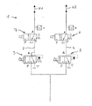
- the single figure of the drawings shows a schematically simplified depiction of an activation control device 1 for the clutch packs (represented by arrows K 1 and K 2 ) of an hydraulic double clutch that is used with a double clutch transmission (not shown).
- the activation control device 1 comprises a first pressure line 2 that is equipped with a filling valve 3 and a draining valve 7 downstream of the filling valve 3. So, the draining valve 7 is disposed between the filling valve 3 and the clutch pack K 1 .
- a second parallel pressure line 4 is provided having a filling valve 5 and a draining valve 6 downstream of filling valve 5 so that also draining valve 6 is disposed between filling valve 5 and clutch pack K 2 .
- pressure lines 2 and 4 are connected to an oil pressure source that is not depicted in the figure.
- valve terminals P, T, A The connection of the valve terminals P, T, A to the pressure lines 2 and 4 can be gathered from the figure to which is herewith explicitly made reference for the purpose of disclosure.
Abstract
- a first pressure line (2) having a filling valve (3) and leading from an oil pressure source to the first clutch pack (K1); and
a second pressure line (4) having a filling valve (5) and a leading from the oil pressure source to the second clutch pack (K2) wherein
a draining valve (6, 7) is disposed in both the first pressure line (2) and the second pressure line (4) between the filling valves (3, 5, respectively) and the first and second clutch packs (K1, K2), respectively.
Description
- The invention concerns an activation control device for the clutch packs of a hydraulic double clutch.
- Hydraulic double clutches are used for double clutch transmissions and comprise first and second pressure lines leading from an oil pressure source via respective filling valves in each pressure line to the first and the second clutch pack, respectively.
- It is an object underlying the present invention to provide an activation control device according to the preamble part of
claim 1 that has improved and safer operating characteristics. - The solution of this object is achieved by the features of
claim 1. - The activation control device according to the present invention comprises a draining valve in each of the pressures lines between the filling valve and the clutch pack. This results in the advantage of a minimization of the pressure drop upon draining and provides a redundant control option in case of a valve failure. So, as both pressure lines comprise one valve primarily intended for supplying oil to the clutch packs and thus controlling the clutch pressure and another valve for the purpose of draining the reaction time of the entire activation control device is shorter, and thus the torque transmission can be optimized.
- The dependent claims contain advantageous embodiments of the present invention.
- The filling valve is preferably a proportional pressure reducing valves. The draining valve is preferably a on-off 3/2 valve.
- According to a specifically preferred embodiment the diameter of the spool of the draining valve is bigger than the diameter of the spool of the filling valve.
- Furthermore, it is possible that the drain valves have a symmetric spool design whereas the filling valve can have an asymmetric spool design. However, in general it is also possible that both valve types have the same spool design.
- Further features and advantages of the present invention will become apparent from the following description of the single figure of the drawings.
- The single figure of the drawings shows a schematically simplified depiction of an
activation control device 1 for the clutch packs (represented by arrows K1 and K2) of an hydraulic double clutch that is used with a double clutch transmission (not shown). - The
activation control device 1 comprises afirst pressure line 2 that is equipped with afilling valve 3 and a draining valve 7 downstream of thefilling valve 3. So, the draining valve 7 is disposed between thefilling valve 3 and the clutch pack K1. - Furthermore, a second parallel pressure line 4 is provided having a filling valve 5 and a draining valve 6 downstream of filling valve 5 so that also draining valve 6 is disposed between filling valve 5 and clutch pack K2.
- Of course, the
pressure lines 2 and 4 are connected to an oil pressure source that is not depicted in the figure. - The connection of the valve terminals P, T, A to the
pressure lines 2 and 4 can be gathered from the figure to which is herewith explicitly made reference for the purpose of disclosure. -
- 1
- activation control device
- 2
- first pressure line
- 3
- filling valve in the
first pressure line 2 - 4
- second pressure line
- 5
- filling valve in the second pressure line 4
- 6
- draining valve in the second pressure line 4
- 7
- draining valve in the
first pressure line 2 - P,T, A
- valve terminals
- K1
- first clutch pack
- K2
- second clutch pack of the hydraulic double clutch
Claims (6)
- Activation control device (1) for the clutch packs (K1, K2) of a hydraulic double clutch comprising:- a first pressure line (2) having a filling valve (3) and leading from an oil pressure source to the first clutch pack (K1); and- a second pressure line (4) having a filling valve (5) and leading from the oil pressure source to the second clutch pack (K2) being characterised in- that a draining valve (6, 7) is disposed in both the first pressure line (2) and the second pressure line (4) between the filling valves (3, 5, respectively) and the first and second clutch packs (K1, K2), respectively.
- Activation control device according to claim 1 being characterised in that the filling valve is a proportional pressure reducing valve (6) and the draining valve an on-off 3/2 valve (7).
- Activation control device according to claim 1 or 2, being characterised in that the diameter of the spool of the draining valves (6, 7) is bigger than the diameter of the spool of the filling valves (3, 5).
- Activation control device according to one of claims 1 to 3, being characterised in that the draining valves (6, 7) have a symmetric spool design.
- Activation control device according to one of claims 1 to 4, being characterised in that the filling valve (3, 5) have an asymmetric spool design.
- Activation control device according to one of claims 1 to 5, being characterised in that the first and the second pressure lines, of 2 and 4 are disposed in parallel branching off from a central pressure line to the oil pressure source.
Priority Applications (8)
| Application Number | Priority Date | Filing Date | Title |
|---|---|---|---|
| AT05009008T ATE441792T1 (en) | 2005-04-25 | 2005-04-25 | ACTUATING CONTROL DEVICE FOR THE PLATES OF A HYDRAULIC DOUBLE CLUTCH |
| DE602005016371T DE602005016371D1 (en) | 2005-04-25 | 2005-04-25 | Actuation control device for the slats of a hydraulic double clutch |
| EP05009008A EP1717473B1 (en) | 2005-04-25 | 2005-04-25 | Activation control device for the clutch packs of a hydraulic double clutch |
| JP2008508141A JP2008538806A (en) | 2005-04-25 | 2006-04-25 | Operation control device used for clutch pack of hydraulic double clutch |
| KR1020077024382A KR20080004506A (en) | 2005-04-25 | 2006-04-25 | Activation control device for the clutch packs of a hydraulic double clutch |
| CNA2006800138000A CN101163901A (en) | 2005-04-25 | 2006-04-25 | Activation control device for the clutch packs of a hydraulic double clutch |
| PCT/EP2006/003825 WO2006114282A1 (en) | 2005-04-25 | 2006-04-25 | Activation control device for the clutch packs of a hydraulic double clutch |
| US11/924,392 US7695388B2 (en) | 2005-04-25 | 2007-10-25 | Activation control device for the clutch packs of a hydraulic double clutch |
Applications Claiming Priority (1)
| Application Number | Priority Date | Filing Date | Title |
|---|---|---|---|
| EP05009008A EP1717473B1 (en) | 2005-04-25 | 2005-04-25 | Activation control device for the clutch packs of a hydraulic double clutch |
Publications (2)
| Publication Number | Publication Date |
|---|---|
| EP1717473A1 true EP1717473A1 (en) | 2006-11-02 |
| EP1717473B1 EP1717473B1 (en) | 2009-09-02 |
Family
ID=34935681
Family Applications (1)
| Application Number | Title | Priority Date | Filing Date |
|---|---|---|---|
| EP05009008A Active EP1717473B1 (en) | 2005-04-25 | 2005-04-25 | Activation control device for the clutch packs of a hydraulic double clutch |
Country Status (8)
| Country | Link |
|---|---|
| US (1) | US7695388B2 (en) |
| EP (1) | EP1717473B1 (en) |
| JP (1) | JP2008538806A (en) |
| KR (1) | KR20080004506A (en) |
| CN (1) | CN101163901A (en) |
| AT (1) | ATE441792T1 (en) |
| DE (1) | DE602005016371D1 (en) |
| WO (1) | WO2006114282A1 (en) |
Cited By (8)
| Publication number | Priority date | Publication date | Assignee | Title |
|---|---|---|---|---|
| EP2410212A2 (en) | 2010-07-21 | 2012-01-25 | hofer mechatronik GmbH | Hydraulic control of a dual clutch transmission |
| DE102010036545A1 (en) | 2010-07-21 | 2012-01-26 | Hofer Mechatronik Gmbh | Hydraulic controller for double clutch transmission with hydraulic clutches, includes couplings that are arranged separately in hydraulic line |
| DE102010037243A1 (en) | 2010-08-31 | 2012-03-01 | Hofer Mechatronik Gmbh | Hydraulic controller for double clutch transmission with hydraulic clutches, includes couplings that are arranged separately in hydraulic line |
| EP2458249A1 (en) | 2010-11-25 | 2012-05-30 | Hoerbiger Drivetrain Mechatronics B.V.B.A. | Method of controlling a double clutch in a vehicle transmission, and clutch control system for controlling a double clutch |
| FR2992384A1 (en) * | 2012-06-26 | 2013-12-27 | Borgwarner Inc | DOUBLE OIL CLUTCH TRANSMISSION |
| DE102006016397B4 (en) * | 2006-04-07 | 2014-08-07 | Hofer Mechatronik Gmbh | Transmission and a method for controlling a transmission for a motor vehicle |
| DE102006063034B3 (en) * | 2006-04-07 | 2018-02-01 | Hofer Mechatronik Gmbh | Method for controlling a transmission for a motor vehicle |
| DE102010064634B3 (en) * | 2010-08-31 | 2020-09-03 | Hofer Powertrain Innovation Gmbh | Hydraulic control of a dual clutch transmission and method for operating such a control |
Families Citing this family (9)
| Publication number | Priority date | Publication date | Assignee | Title |
|---|---|---|---|---|
| EP2959902A1 (en) | 2009-07-23 | 2015-12-30 | Novartis AG | Use of azabicycloalkyl derivatives for the treatment or prevention of ataxia |
| DE102012110746B4 (en) * | 2012-11-09 | 2020-01-30 | Getrag Ford Transmissions Gmbh | Method for operating an automated dual clutch transmission in a motor vehicle |
| CN104937302B (en) * | 2013-01-18 | 2018-04-13 | 舍弗勒技术股份两合公司 | For controling the fluid system and method for clutch apparatus |
| DE102013215906A1 (en) * | 2013-08-12 | 2015-02-12 | Zf Friedrichshafen Ag | Method and control device for operating an assembly of a vehicle |
| US20170138417A1 (en) * | 2014-03-24 | 2017-05-18 | Schaeffler Technologies AG & Co. KG | Actuator which can be drive-coupled and has a variable displacement pump |
| US10837503B2 (en) | 2015-11-26 | 2020-11-17 | Isuzu Motors Limited | Hydraulic-oil control device |
| JP6329189B2 (en) * | 2016-03-01 | 2018-05-23 | 本田技研工業株式会社 | Control device for automatic transmission |
| WO2018055192A1 (en) | 2016-09-26 | 2018-03-29 | Hofer Mechatronik Gmbh | Hydraulic system for supplying i.a. clutch actuators |
| CN107448598B (en) * | 2017-07-31 | 2019-04-16 | 安徽江淮汽车集团股份有限公司 | A kind of clutch control of gearbox |
Citations (3)
| Publication number | Priority date | Publication date | Assignee | Title |
|---|---|---|---|---|
| JPS61252922A (en) * | 1985-05-01 | 1986-11-10 | Kubota Ltd | Hydraulic clutch structure in farm working machine |
| EP0356527A1 (en) * | 1988-02-19 | 1990-03-07 | Kabushiki Kaisha Komatsu Seisakusho | Clutch switching circuit of nonstage transmission |
| EP1503101A1 (en) * | 2003-07-26 | 2005-02-02 | ZF Sachs AG | Hydraulically actuated multiple disc clutch |
Family Cites Families (10)
| Publication number | Priority date | Publication date | Assignee | Title |
|---|---|---|---|---|
| FR2313608A1 (en) * | 1975-06-04 | 1976-12-31 | Renault | HYDRAULIC CONTROL DEVICE FOR AUTOMATIC GEARBOXES |
| JPS6159027A (en) * | 1984-08-31 | 1986-03-26 | Aisin Seiki Co Ltd | Hydraulic controller |
| DE3856273T2 (en) * | 1987-05-22 | 1999-06-17 | Komatsu Mfg Co Ltd | Device and method for controlling a lock-up clutch |
| DE3810013A1 (en) * | 1988-03-24 | 1989-10-12 | Rexroth Mannesmann Gmbh | Method and device for applying pressure to actuators on gearshift elements of a vehicle transmission |
| JP2881175B2 (en) * | 1991-12-03 | 1999-04-12 | アイシン・エィ・ダブリュ株式会社 | Servo hydraulic controller for automatic transmission |
| EP0892894B1 (en) * | 1997-01-22 | 2002-12-11 | Voith Turbo GmbH & Co. KG | Process for operating a hydrodynamic clutch and hydrodynamic clutch |
| JP4172672B2 (en) * | 1999-03-17 | 2008-10-29 | 株式会社小松製作所 | Transmission clutch pressure control device |
| DE10103843A1 (en) * | 2001-01-30 | 2002-08-01 | Zf Sachs Ag | Hydraulic clutch system |
| US7441643B2 (en) * | 2005-12-20 | 2008-10-28 | Caterpillar Inc. | Transmission having a backup latch mechanism |
| US7444809B2 (en) * | 2006-01-30 | 2008-11-04 | Caterpillar Inc. | Hydraulic regeneration system |
-
2005
- 2005-04-25 EP EP05009008A patent/EP1717473B1/en active Active
- 2005-04-25 DE DE602005016371T patent/DE602005016371D1/en active Active
- 2005-04-25 AT AT05009008T patent/ATE441792T1/en not_active IP Right Cessation
-
2006
- 2006-04-25 JP JP2008508141A patent/JP2008538806A/en active Pending
- 2006-04-25 CN CNA2006800138000A patent/CN101163901A/en active Pending
- 2006-04-25 WO PCT/EP2006/003825 patent/WO2006114282A1/en active Application Filing
- 2006-04-25 KR KR1020077024382A patent/KR20080004506A/en not_active Application Discontinuation
-
2007
- 2007-10-25 US US11/924,392 patent/US7695388B2/en active Active
Patent Citations (3)
| Publication number | Priority date | Publication date | Assignee | Title |
|---|---|---|---|---|
| JPS61252922A (en) * | 1985-05-01 | 1986-11-10 | Kubota Ltd | Hydraulic clutch structure in farm working machine |
| EP0356527A1 (en) * | 1988-02-19 | 1990-03-07 | Kabushiki Kaisha Komatsu Seisakusho | Clutch switching circuit of nonstage transmission |
| EP1503101A1 (en) * | 2003-07-26 | 2005-02-02 | ZF Sachs AG | Hydraulically actuated multiple disc clutch |
Non-Patent Citations (1)
| Title |
|---|
| PATENT ABSTRACTS OF JAPAN vol. 011, no. 105 (M - 577) 3 April 1987 (1987-04-03) * |
Cited By (19)
| Publication number | Priority date | Publication date | Assignee | Title |
|---|---|---|---|---|
| DE102006063034B3 (en) * | 2006-04-07 | 2018-02-01 | Hofer Mechatronik Gmbh | Method for controlling a transmission for a motor vehicle |
| DE102006016397B4 (en) * | 2006-04-07 | 2014-08-07 | Hofer Mechatronik Gmbh | Transmission and a method for controlling a transmission for a motor vehicle |
| EP2685136A2 (en) | 2010-07-21 | 2014-01-15 | hofer mechatronik GmbH | Hydraulic control of a dual clutch transmission |
| EP2410213A3 (en) * | 2010-07-21 | 2012-05-16 | hofer mechatronik GmbH | Transmission hydraulics for a transmission with multiple clutches and control method with hydraulic valves for transmissions comprising multiple clutches which provide improved safety during operation |
| DE102010036545A1 (en) | 2010-07-21 | 2012-01-26 | Hofer Mechatronik Gmbh | Hydraulic controller for double clutch transmission with hydraulic clutches, includes couplings that are arranged separately in hydraulic line |
| EP2557336A2 (en) | 2010-07-21 | 2013-02-13 | hofer mechatronik GmbH | Hydraulic control of a double clutch transmission and control method thereof |
| EP3043089A1 (en) | 2010-07-21 | 2016-07-13 | hofer mechatronik GmbH | Treatment of hydraulics agent of a transmission hydraulic system and method for operating the transmission hydraulic system |
| EP2410213A2 (en) | 2010-07-21 | 2012-01-25 | hofer mechatronik GmbH | Transmission hydraulics for a transmission with multiple clutches and control method with hydraulic valves for transmissions comprising multiple clutches which provide improved safety during operation |
| DE102010036545B4 (en) * | 2010-07-21 | 2015-01-08 | Hofer Mechatronik Gmbh | Transmission hydraulics of a multiple clutch transmission and control system with multi-clutch hydraulic valves providing increased operational safety |
| EP2410212A2 (en) | 2010-07-21 | 2012-01-25 | hofer mechatronik GmbH | Hydraulic control of a dual clutch transmission |
| DE102010037243A1 (en) | 2010-08-31 | 2012-03-01 | Hofer Mechatronik Gmbh | Hydraulic controller for double clutch transmission with hydraulic clutches, includes couplings that are arranged separately in hydraulic line |
| DE102010064634B3 (en) * | 2010-08-31 | 2020-09-03 | Hofer Powertrain Innovation Gmbh | Hydraulic control of a dual clutch transmission and method for operating such a control |
| DE102010037243B4 (en) * | 2010-08-31 | 2016-11-17 | Hofer Mechatronik Gmbh | Hydraulic control of a dual clutch transmission and method for operating two trained as actuators clutches |
| US9103388B2 (en) | 2010-11-25 | 2015-08-11 | Transmisiones Y Equipos Mecanicos S.A. De C.V. | Method of controlling a double clutch in a vehicle transmission, and clutch control system for controlling a double clutch |
| US9683660B2 (en) | 2010-11-25 | 2017-06-20 | Transmisiones Y Equipos Mecanicos, S.A. De C.V. | Method of controlling a double clutch in a vehicle transmission, and clutch control system for controlling a double clutch |
| WO2012069165A1 (en) | 2010-11-25 | 2012-05-31 | Hoerbiger Drivetrain Mechatronics B.V.B.A. | Method of controlling a double clutch in a vehicle transmission, and clutch control system for controlling a double clutch |
| EP2458249A1 (en) | 2010-11-25 | 2012-05-30 | Hoerbiger Drivetrain Mechatronics B.V.B.A. | Method of controlling a double clutch in a vehicle transmission, and clutch control system for controlling a double clutch |
| EP2864675A4 (en) * | 2012-06-26 | 2016-08-31 | Borgwarner Inc | Dual-wet-clutch transmission |
| FR2992384A1 (en) * | 2012-06-26 | 2013-12-27 | Borgwarner Inc | DOUBLE OIL CLUTCH TRANSMISSION |
Also Published As
| Publication number | Publication date |
|---|---|
| US20090131219A1 (en) | 2009-05-21 |
| ATE441792T1 (en) | 2009-09-15 |
| US7695388B2 (en) | 2010-04-13 |
| CN101163901A (en) | 2008-04-16 |
| DE602005016371D1 (en) | 2009-10-15 |
| JP2008538806A (en) | 2008-11-06 |
| WO2006114282A1 (en) | 2006-11-02 |
| KR20080004506A (en) | 2008-01-09 |
| EP1717473B1 (en) | 2009-09-02 |
Similar Documents
| Publication | Publication Date | Title |
|---|---|---|
| EP1717473A1 (en) | Activation control device for the clutch packs of a hydraulic double clutch | |
| CN107208715B (en) | Fluid assembly | |
| JP5111069B2 (en) | Hydraulic control system for automatic transmission for vehicles | |
| KR102142337B1 (en) | Continuously variable transmission with a hydraulic control system | |
| EP3133310A1 (en) | Dual clutch device | |
| EP2292951A1 (en) | Control system for transmission | |
| CN101255921A (en) | Hydraulic control device for automated double clutch transmission | |
| CN103133688A (en) | Hydraulic pressure control apparatus for automatic transmission | |
| EP2410211A1 (en) | Hydraulic control device for automatic transmission | |
| AU778403B2 (en) | A manual valve of a hydraulic pressure control system for an automatic transmission of a vehicle | |
| CN102597564A (en) | Hydraulic control device for friction clutch for vehicle | |
| KR100957163B1 (en) | Hydraulic control system of automatic transmission for vehicles | |
| KR20200062744A (en) | Oil pressure control system for a vehicle with an auto transmission and an auto transmission | |
| US20160003309A1 (en) | Hydraulic control device and hydraulic control method | |
| EP3882062B1 (en) | Drive apparatus for hybrid vehicle | |
| CN210623538U (en) | Hydraulic control device for automatic transmission | |
| JP5662110B2 (en) | Hydraulic control system for continuously variable transmission of automobile | |
| CN109899514B (en) | System and method for reducing clutch fill time | |
| GB2604511A (en) | Power off hydraulic default strategy | |
| EP3690286A1 (en) | Power train device for vehicles | |
| CN110594405A (en) | Hydraulic control device for automatic transmission | |
| US20140151177A1 (en) | Device for actuating a frictional converter lock-up clutch of a hydrodynamic torque converter | |
| US5207123A (en) | Electrohydraulic control for an automatic transmission | |
| CN107816546A (en) | A kind of method of hydraulic control system of automatic speed changer and the application system | |
| KR100305827B1 (en) | Hydraulic control system for continuously variable transmission |
Legal Events
| Date | Code | Title | Description |
|---|---|---|---|
| PUAI | Public reference made under article 153(3) epc to a published international application that has entered the european phase |
Free format text: ORIGINAL CODE: 0009012 |
|
| AK | Designated contracting states |
Kind code of ref document: A1 Designated state(s): AT BE BG CH CY CZ DE DK EE ES FI FR GB GR HU IE IS IT LI LT LU MC NL PL PT RO SE SI SK TR |
|
| AX | Request for extension of the european patent |
Extension state: AL BA HR LV MK YU |
|
| 17P | Request for examination filed |
Effective date: 20070105 |
|
| 17Q | First examination report despatched |
Effective date: 20070503 |
|
| AKX | Designation fees paid |
Designated state(s): AT DE FR GB IT |
|
| GRAP | Despatch of communication of intention to grant a patent |
Free format text: ORIGINAL CODE: EPIDOSNIGR1 |
|
| GRAS | Grant fee paid |
Free format text: ORIGINAL CODE: EPIDOSNIGR3 |
|
| GRAA | (expected) grant |
Free format text: ORIGINAL CODE: 0009210 |
|
| AK | Designated contracting states |
Kind code of ref document: B1 Designated state(s): AT DE FR GB IT |
|
| REF | Corresponds to: |
Ref document number: 602005016371 Country of ref document: DE Date of ref document: 20091015 Kind code of ref document: P |
|
| PG25 | Lapsed in a contracting state [announced via postgrant information from national office to epo] |
Ref country code: AT Free format text: LAPSE BECAUSE OF FAILURE TO SUBMIT A TRANSLATION OF THE DESCRIPTION OR TO PAY THE FEE WITHIN THE PRESCRIBED TIME-LIMIT Effective date: 20090902 |
|
| PLBE | No opposition filed within time limit |
Free format text: ORIGINAL CODE: 0009261 |
|
| STAA | Information on the status of an ep patent application or granted ep patent |
Free format text: STATUS: NO OPPOSITION FILED WITHIN TIME LIMIT |
|
| 26N | No opposition filed |
Effective date: 20100603 |
|
| REG | Reference to a national code |
Ref country code: FR Ref legal event code: TP Owner name: HOERBIGER DRIVETRAIN MECHATRONICS B.V.B.A., BE Effective date: 20111206 |
|
| REG | Reference to a national code |
Ref country code: GB Ref legal event code: 732E Free format text: REGISTERED BETWEEN 20120112 AND 20120118 |
|
| REG | Reference to a national code |
Ref country code: DE Ref legal event code: R082 Ref document number: 602005016371 Country of ref document: DE Representative=s name: PRINZ & PARTNER PATENTANWAELTE RECHTSANWAELTE, DE |
|
| REG | Reference to a national code |
Ref country code: DE Ref legal event code: R082 Ref document number: 602005016371 Country of ref document: DE Representative=s name: PRINZ & PARTNER PATENTANWAELTE RECHTSANWAELTE, DE Effective date: 20120319 Ref country code: DE Ref legal event code: R081 Ref document number: 602005016371 Country of ref document: DE Owner name: TRANSMISIONES Y EQUIPOS MECANICOS, S.A. DE C.V, MX Free format text: FORMER OWNER: HOERBIGER ANTRIEBSTECHNIK GMBH, 86956 SCHONGAU, DE Effective date: 20120319 Ref country code: DE Ref legal event code: R082 Ref document number: 602005016371 Country of ref document: DE Representative=s name: PRINZ & PARTNER MBB PATENTANWAELTE RECHTSANWAE, DE Effective date: 20120319 |
|
| REG | Reference to a national code |
Ref country code: DE Ref legal event code: R082 Ref document number: 602005016371 Country of ref document: DE Representative=s name: PRINZ & PARTNER PATENTANWAELTE RECHTSANWAELTE, DE |
|
| REG | Reference to a national code |
Ref country code: FR Ref legal event code: TP Owner name: TRANSMISIONES Y EQUIPOS MECANICOS, S.A. DE C.V, MX Effective date: 20131010 |
|
| REG | Reference to a national code |
Ref country code: GB Ref legal event code: 732E Free format text: REGISTERED BETWEEN 20131024 AND 20131030 |
|
| REG | Reference to a national code |
Ref country code: DE Ref legal event code: R082 Ref document number: 602005016371 Country of ref document: DE Representative=s name: PRINZ & PARTNER PATENTANWAELTE RECHTSANWAELTE, DE Effective date: 20131014 Ref country code: DE Ref legal event code: R081 Ref document number: 602005016371 Country of ref document: DE Owner name: TRANSMISIONES Y EQUIPOS MECANICOS, S.A. DE C.V, MX Free format text: FORMER OWNER: HOERBIGER DRIVETRAIN MECHATRONICS B.V.B.A., LOPPEM, BE Effective date: 20131014 Ref country code: DE Ref legal event code: R082 Ref document number: 602005016371 Country of ref document: DE Representative=s name: PRINZ & PARTNER MBB PATENTANWAELTE RECHTSANWAE, DE Effective date: 20131014 |
|
| REG | Reference to a national code |
Ref country code: FR Ref legal event code: PLFP Year of fee payment: 12 |
|
| REG | Reference to a national code |
Ref country code: FR Ref legal event code: PLFP Year of fee payment: 13 |
|
| REG | Reference to a national code |
Ref country code: FR Ref legal event code: PLFP Year of fee payment: 14 |
|
| REG | Reference to a national code |
Ref country code: DE Ref legal event code: R082 Ref document number: 602005016371 Country of ref document: DE Representative=s name: VOSSIUS & PARTNER PATENTANWAELTE RECHTSANWAELT, DE |
|
| P01 | Opt-out of the competence of the unified patent court (upc) registered |
Effective date: 20230512 |
|
| PGFP | Annual fee paid to national office [announced via postgrant information from national office to epo] |
Ref country code: IT Payment date: 20230426 Year of fee payment: 19 Ref country code: FR Payment date: 20230420 Year of fee payment: 19 Ref country code: DE Payment date: 20230420 Year of fee payment: 19 |
|
| PGFP | Annual fee paid to national office [announced via postgrant information from national office to epo] |
Ref country code: GB Payment date: 20230419 Year of fee payment: 19 |