EP1717389A1 - Door handle - Google Patents
Door handle Download PDFInfo
- Publication number
- EP1717389A1 EP1717389A1 EP05380083A EP05380083A EP1717389A1 EP 1717389 A1 EP1717389 A1 EP 1717389A1 EP 05380083 A EP05380083 A EP 05380083A EP 05380083 A EP05380083 A EP 05380083A EP 1717389 A1 EP1717389 A1 EP 1717389A1
- Authority
- EP
- European Patent Office
- Prior art keywords
- handle
- actuator
- support
- rotation
- door handle
- Prior art date
- Legal status (The legal status is an assumption and is not a legal conclusion. Google has not performed a legal analysis and makes no representation as to the accuracy of the status listed.)
- Withdrawn
Links
Images




Classifications
-
- E—FIXED CONSTRUCTIONS
- E05—LOCKS; KEYS; WINDOW OR DOOR FITTINGS; SAFES
- E05B—LOCKS; ACCESSORIES THEREFOR; HANDCUFFS
- E05B13/00—Devices preventing the key or the handle or both from being used
- E05B13/002—Devices preventing the key or the handle or both from being used locking the handle
- E05B13/004—Devices preventing the key or the handle or both from being used locking the handle by locking the spindle, follower, or the like
Definitions
- the present invention comprises a locking element of the type of handles that comprise a locking element by means of which rotation of the handle may be blocked and consequently the opening of the door is prevented. Furthermore, another object of the invention is to permit the locking element to be located in the support itself that extends outward through the ornamental element.
- Another object of the invention permits the locking element to be actuated by means of rotation or by means of longitudinal movement.
- Another purpose of the invention is to facilitate the arrangement of the locking element in the support itself of the handle simply and without interrupting a perimetric channel that the support has, for which purpose the locking control is mounted on a guiding part that is radially inserted in the edge of the support giving continuity to the cited channel.
- Another purpose of the invention consists of the blocking element being able to be of the push-button type as well as of the runner type.
- Mechanisms for opening and closing doors which comprise a support for fastening to the door are known, mechanisms wherein with the possibility of rotation a handle is put in place which by means of a square bar and a mechanism, is connected to a thumb latch in order to open or close the door by means of actuating the handle.
- the handle is helped by means of a spring and the retaining of said handle in the support is carried out by a stopping element and a retaining washer in such a way that the stopping element, by action of the spring, keeps the handle in a fixed position, in such a way that the corresponding operation allows the opening, in such a way that rotation of the handle is limited by means of the stopping element.
- door handles with a blocking device are known and these handles have a support for fastening to the corresponding door.
- the cited device is provided with a doorknob and a rotation recovery mechanism of the doorknob.
- the cited support has a control for stopping the cited rotation, as well as a perimetric channel that houses a joint and that facilitates retention of an ornamental crown.
- the invention comprises a door handle that comprise a support for fastening to the door, wherein a handle is retained with the possibility of rotation, by means of a stopping element and a retaining washer. Besides, it also comprises a locking element that is provided with an actuator in order to permit the rotation of the handle, and to prevent opening.
- the support is covered by an ornamental element.
- a locking element is located in the support and extends outward through the ornamental element and the cited locking element finishes in an actuator after having extended outward from the cited ornamental element.
- the locking element comprises a shaft that runs through a hole made in the support and in its bottom end it ends in a movable blocking body in order to be located in the path of the stopping element upon actuating the actuator, preventing the rotation of the stopping element and consequently the handle upon actuating the handle.
- the actuator, shaft and the blocking body of the handle may be moved longitudinally or angularly.
- the support of the handle may have a housing of the blocking body, wherein rotation of an stopping element is allowed in such a way that when pressed the actuator comes out of the housing in order to be located in the corresponding path, thus preventing movement thereof.
- the blocking body may be asymmetric so that in one position of the actuator the body does not intercede the path of a rotation recovery mechanism.
- the ornamental element may be provided with a hole wherein the actuator is located.
- the locking control is assembled on a guiding part that is inserted radially in the edge of the support giving continuity to the channel made in the support, whereas in other embodiments same may be included perpendicularly instead of radially.
- the blocking control may have the shape of a push button, in such a way that its pressure defines that a stopping element arranged in the inside end blocks the rotation recovery mechanism and that its traction releases said mechanism.
- the locking element may be drawn out or deactivated by means of a small pin when the blocking device is not required.
- the first embodiment is a door handle as represented in figures 1 to 4.
- This door handle has the handle itself (2) that connects with the corresponding support (1), which has the corresponding fastening holes and a locking element of the handle (6).
- This element (6) has an actuator of the locking element (6a) and an axis of the locking element (6b).
- the element (6) may move in both directions of the axial direction of the main shaft thereof.
- figure 3 and in figure 4 one can see how the assembly that we have been describing for this first embodiment is.
- a handle stop (3) that is inserted in the end of the handle by means of a retaining washer (4) or circular clip, which is arranged in a groove provided for in the end of the handle (2). Retention of the handle (2) is caused with the possibility of rotation.
- the stopping element (3) has some extensions housed in some grooves, in such a way that when rotation of the handle (2) is caused, the handle causes the stopping element (3) to rotate, which has two stops (3a) and (3b) complementary to a projection (1a) provided for in the support (1) and whose purpose is explained hereinafter.
- the handle is aided by a spring (not represented), which keeps the stop (3a) pressed against the projection (1a) in such a way that the handle is kept immobile in its horizontal position. If in this state the handle is actuated causing rotation thereof, rotation is caused up to the point where the stop (3b) makes contact with the projection (1a), which permits the door to be opened.
- the support (1) is provided with a housing wherein the blocking element (6c) of the locking element (6) is located, just as it is represented in figure 4, in such a way that rotation of the handle (2) and of the stopping element (3) is made possible as described above.
- the second embodiment which is shown in figures 5, 6 and 7 shows another possible embodiment of the characteristics that have been described up to now in such a way that we have a support (1), a handle (2), an ornamental element (5) and a locking element (7), when the handle is seen in its area of use. Subsequently, in this second embodiment, one can also see a circular clip (4) fastened in the corresponding groove, aside from other structures that have been cited above.
- the main difference with the preceding embodiment consists of the locking element (6), referred to as (7) in this embodiment, has angular rotation, namely, movement in a plane perpendicular to the main shaft described for the first embodiment.
- the locking element is comprised of an actuator (7a), a shaft (7b) and a blocking element (7c) that has an asymmetric shape, in such a way that in a certain position of the actuator (7a) the blocking element is outside the path of the stops (3a) and (3b) of the stopping element (3), which permits opening to be carried out, whereas if the actuator (7a) is rotated the blocking element (7c) is in the path of the stopping element (3) in such a way that when turning the handle (2) and due to said stopping element (3), the stop (3b) knocks against the blocking element (7c), preventing opening.
- the third embodiment represented in figures 8, 9, 10 and 11 shows an embodiment of the handle wherein the design is perhaps emphasized a bit more, although the basic structure is very similar to that of the two preceding embodiments.
- the handle in this case (9), has some more noticeable roundings than the handles of the preceding embodiments.
- the ornamental element (12) which is coupled to the support (10) in a way similar to that of the preceding cases, has on its inside edge a notch that is going to permit the passing of the locking control (11).
- the support (10) has a perimetric channel (16) which in this case is interrupted by a small cut provided for in order to house a guiding part (15) related to the cited locking control (11). This can all be seen in figures 8 and 9.
- FIGS 10 and 11 wherein one can see mechanisms corresponding to this third embodiment, give more detail of the elements such as the guiding part (15), a rotation recovery element (13) and a movable part (14) of the locking control (11).
- the locking control (11) is formed on a guiding part (19), as it was said above, that inserts radially in the edge of the support as one can see in the figures.
- the guiding part (15) has a shape such that it gives continuity to the perimetric channel (16).
- the control (11) has a push-button shape, in such a way that its pressure determines that the stopping element (14) blocks the rotation recovery mechanism, whereas its traction releases said mechanism.
- the cited locking control can be replaced by a small pin when the locking device is not required in the corresponding door.
- the fourth embodiment of the invention is rather similar to the third embodiment, with the main difference that the locking control, in this case (17), has radial movement for its operation instead of it being a push button.
- the locking control in this case (17)
- Figures 14 and 16 also show specific elements, but from rear perspectives, that is to say, the most technical parts to be included in the corresponding door.
- this fourth embodiment there is also a support for fastening to the door provided with a doorknob and a rotation recovery mechanism of the doorknob or handle (2).
- the support has a locking control (17) of the corresponding rotation and a perimetric channel (16) that houses a joint to facilitate retention of the ornamental crown (20).
- the locking control of this fourth embodiment is also assembled on a guiding part (19), which is similar to the guiding part (18) or above-cited stopping element. This part is radially inserted in the edge of the support as one can see in figure 14, thus giving continuity to the perimetric channel (16), in such a way that the placement of the joint is done correctly and simply.
- the locking control of this fourth embodiment has shape so that its radial movement towards the inside defines a stop. The radial movement towards the outside of this control releases said stop.
Landscapes
- Lock And Its Accessories (AREA)
Abstract
It comprises a support (1) for fastening to the door, wherein a handle (2) with the possibility of rotation is retained by means of a stopping element (3) and a retaining washer (4). It also comprises a locking element that is provided with an actuator in order to permit blocking the rotation of the handle and preventing it from opening. The support (1) is covered by an ornamental element (5) and there may be a perimetric channel that houses a joint that facilitates the retaining of an ornamental crown. The locking element (6,7) is located in the support (1) and extends outward through the ornamental element (5), in whose area it ends in the actuator (6a, 7a).
Description
- As described in the title of this specification, the present invention comprises a locking element of the type of handles that comprise a locking element by means of which rotation of the handle may be blocked and consequently the opening of the door is prevented. Furthermore, another object of the invention is to permit the locking element to be located in the support itself that extends outward through the ornamental element.
- Another object of the invention permits the locking element to be actuated by means of rotation or by means of longitudinal movement.
- Another purpose of the invention is to facilitate the arrangement of the locking element in the support itself of the handle simply and without interrupting a perimetric channel that the support has, for which purpose the locking control is mounted on a guiding part that is radially inserted in the edge of the support giving continuity to the cited channel.
- Another purpose of the invention consists of the blocking element being able to be of the push-button type as well as of the runner type.
- Mechanisms for opening and closing doors, which comprise a support for fastening to the door are known, mechanisms wherein with the possibility of rotation a handle is put in place which by means of a square bar and a mechanism, is connected to a thumb latch in order to open or close the door by means of actuating the handle.
- Normally, the handle is helped by means of a spring and the retaining of said handle in the support is carried out by a stopping element and a retaining washer in such a way that the stopping element, by action of the spring, keeps the handle in a fixed position, in such a way that the corresponding operation allows the opening, in such a way that rotation of the handle is limited by means of the stopping element.
- When it is necessary to provide these elements in order to prevent opening from the outside, there is a locking element that prevents opening. In some cases this operation is done by means of an independent element, which constitutes an inconvenience as it is necessary to carry out the assembly process independently. In other cases the inclusion of the locking element in the handle is provided for, in which case the handle must have a special shape wherein said housing element should be located. The latter affects the appearance of the handle and the complexity of its structure.
- On the other hand, door handles with a blocking device are known and these handles have a support for fastening to the corresponding door. The cited device is provided with a doorknob and a rotation recovery mechanism of the doorknob. The cited support has a control for stopping the cited rotation, as well as a perimetric channel that houses a joint and that facilitates retention of an ornamental crown. These handles have inconveniences such as that the assembly or inclusion of the blocking device is relatively complex, since the course of the cited perimetric channel does not have to be interrupted or impeded.
- In order to obtain the indicated aims and to prevent the inconveniences of the prior art, the invention comprises a door handle that comprise a support for fastening to the door, wherein a handle is retained with the possibility of rotation, by means of a stopping element and a retaining washer. Besides, it also comprises a locking element that is provided with an actuator in order to permit the rotation of the handle, and to prevent opening. The support is covered by an ornamental element. Besides, in certain embodiments there is a perimetric channel that houses a joint that facilitates retaining an ornamental crown.
- As a novel feature, a locking element is located in the support and extends outward through the ornamental element and the cited locking element finishes in an actuator after having extended outward from the cited ornamental element.
- In an embodiment of the invention, the locking element comprises a shaft that runs through a hole made in the support and in its bottom end it ends in a movable blocking body in order to be located in the path of the stopping element upon actuating the actuator, preventing the rotation of the stopping element and consequently the handle upon actuating the handle.
- The actuator, shaft and the blocking body of the handle may be moved longitudinally or angularly.
- The support of the handle may have a housing of the blocking body, wherein rotation of an stopping element is allowed in such a way that when pressed the actuator comes out of the housing in order to be located in the corresponding path, thus preventing movement thereof.
- Besides, the blocking body may be asymmetric so that in one position of the actuator the body does not intercede the path of a rotation recovery mechanism.
- The ornamental element may be provided with a hole wherein the actuator is located.
- In certain embodiments the locking control is assembled on a guiding part that is inserted radially in the edge of the support giving continuity to the channel made in the support, whereas in other embodiments same may be included perpendicularly instead of radially.
- The blocking control may have the shape of a push button, in such a way that its pressure defines that a stopping element arranged in the inside end blocks the rotation recovery mechanism and that its traction releases said mechanism.
- Finally, the locking element may be drawn out or deactivated by means of a small pin when the blocking device is not required.
- Hereinafter to provide a better understanding of this specification and providing an integral part thereof, a series of figures wherein the object of the invention has been illustrated in an illustrative and non-restrictive manner are attached hereto.
-
- Figure 1 shows a perspective view of an embodiment of the handle of the invention, wherein the locking element is longitudinally movable. This figure shows the ornamental element separate from the support in order to facilitate the understanding of the structure of the entire assembly.
- Figure 2 shows a perspective view of the embodiment of the preceding figure 1, wherein the ornamental element is assembled on the support.
- Figure 3 shows a rear view of the preceding figure, wherein the handle is located in the inoperative position and the locking element is moved in such a way that its blocking part may be inserted in the path to prevent opening.
- Figure 4 represents a partial view of the embodiment cited in the preceding figures but with another arrangements of its elements.
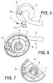
- Figure 5 represents a perspective and exploded view of the invention.
- Figure 6 shows a rear view of the handle of the embodiment of preceding figure 5, in such a way that the locking element is activated.
- Figure 7 represents a partial view similar to the preceding figure 6, wherein the blocking element is deactivated.
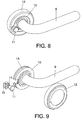
- Figure 8 represents a front perspective view of another embodiment of the door handle with a locking device, made according to the present invention and with all of its components assembled.
- Figure 9 represents an exploded, front perspective view of the handle of the embodiment of preceding figure 8.
- Figure 10 represents a rear perspective view of a detail of the handle of the embodiment of the two preceding figures, the corresponding locking control being unlocked.
- Figure 11 represents a perspective view similar to the view of the preceding figure 10, but the corresponding locking control is locked.
- Figure 12 represents a front perspective view of another embodiment of the door handle with the locking device, according to the present invention and with its components assembled.
- Figure 13 represents an exploded, front view of the handle of the preceding figure 12.
- Figure 14 represents an en exploded, rear perspective view of the handle of preceding figure 12.
- Figure 15 represents a detail of the handle of the preceding figure 12 from a rear, perspective view and the corresponding locking element is unlocked.
- Figure 16 represents a perspective view similar to the one of preceding figure 15, but the corresponding locking control is locked.
- A description of four embodiments of the invention, making reference to the numbering used in the figures.
- Hence, the first embodiment is a door handle as represented in figures 1 to 4. This door handle has the handle itself (2) that connects with the corresponding support (1), which has the corresponding fastening holes and a locking element of the handle (6). This element (6) has an actuator of the locking element (6a) and an axis of the locking element (6b). On the other hand, in this first embodiment there is an ornamental device of the support (5) that has a hole (8) where the cited locking element of the locking element (6) is located. Thus, the element (6) may move in both directions of the axial direction of the main shaft thereof. In figure 3 and in figure 4 one can see how the assembly that we have been describing for this first embodiment is. In order to carry out the corresponding retention of the handle (2) there is a handle stop (3) that is inserted in the end of the handle by means of a retaining washer (4) or circular clip, which is arranged in a groove provided for in the end of the handle (2). Retention of the handle (2) is caused with the possibility of rotation. The stopping element (3) has some extensions housed in some grooves, in such a way that when rotation of the handle (2) is caused, the handle causes the stopping element (3) to rotate, which has two stops (3a) and (3b) complementary to a projection (1a) provided for in the support (1) and whose purpose is explained hereinafter. Hence, the handle is aided by a spring (not represented), which keeps the stop (3a) pressed against the projection (1a) in such a way that the handle is kept immobile in its horizontal position. If in this state the handle is actuated causing rotation thereof, rotation is caused up to the point where the stop (3b) makes contact with the projection (1a), which permits the door to be opened. This characteristic is also valid for the following embodiment. On the other hand, the support (1) is provided with a housing wherein the blocking element (6c) of the locking element (6) is located, just as it is represented in figure 4, in such a way that rotation of the handle (2) and of the stopping element (3) is made possible as described above. If on the contrary, the handle (2) is in its inoperative position, the actuator (6a) of the locking element (6), movement of the locking element (6) that is located in the path of the stopping element (3) that is seen in figure 3, is caused, in such a way that if the handle (2) is actuated the stop (3b) makes contact with the blocking element (6c), thus preventing opening.
- The second embodiment, which is shown in figures 5, 6 and 7 shows another possible embodiment of the characteristics that have been described up to now in such a way that we have a support (1), a handle (2), an ornamental element (5) and a locking element (7), when the handle is seen in its area of use. Subsequently, in this second embodiment, one can also see a circular clip (4) fastened in the corresponding groove, aside from other structures that have been cited above. The main difference with the preceding embodiment consists of the locking element (6), referred to as (7) in this embodiment, has angular rotation, namely, movement in a plane perpendicular to the main shaft described for the first embodiment. Hence, the locking element is comprised of an actuator (7a), a shaft (7b) and a blocking element (7c) that has an asymmetric shape, in such a way that in a certain position of the actuator (7a) the blocking element is outside the path of the stops (3a) and (3b) of the stopping element (3), which permits opening to be carried out, whereas if the actuator (7a) is rotated the blocking element (7c) is in the path of the stopping element (3) in such a way that when turning the handle (2) and due to said stopping element (3), the stop (3b) knocks against the blocking element (7c), preventing opening.
- The third embodiment, represented in figures 8, 9, 10 and 11 shows an embodiment of the handle wherein the design is perhaps emphasized a bit more, although the basic structure is very similar to that of the two preceding embodiments. Hence, the handle, in this case (9), has some more noticeable roundings than the handles of the preceding embodiments. Here, the ornamental element (12), which is coupled to the support (10) in a way similar to that of the preceding cases, has on its inside edge a notch that is going to permit the passing of the locking control (11). The support (10) has a perimetric channel (16) which in this case is interrupted by a small cut provided for in order to house a guiding part (15) related to the cited locking control (11). This can all be seen in figures 8 and 9. Figures 10 and 11, wherein one can see mechanisms corresponding to this third embodiment, give more detail of the elements such as the guiding part (15), a rotation recovery element (13) and a movable part (14) of the locking control (11). Hence, one can see the circular clip and the elements that said clip embraces. Here, the locking control (11) is formed on a guiding part (19), as it was said above, that inserts radially in the edge of the support as one can see in the figures. The guiding part (15) has a shape such that it gives continuity to the perimetric channel (16). In this third embodiment, the control (11) has a push-button shape, in such a way that its pressure determines that the stopping element (14) blocks the rotation recovery mechanism, whereas its traction releases said mechanism. Besides, in this third embodiment, the cited locking control can be replaced by a small pin when the locking device is not required in the corresponding door.
- The fourth embodiment of the invention, represented in figures 12 to 16, is rather similar to the third embodiment, with the main difference that the locking control, in this case (17), has radial movement for its operation instead of it being a push button. Hence, in figures 12 and 13 one can see elements such as the ornamental crown (20), the support (10), the handle (9), the locking control (17) and other more specific elements of this embodiments, such as for example the guiding part (19) and the stopping element (18). Figures 14, 15 and 16 also show specific elements, but from rear perspectives, that is to say, the most technical parts to be included in the corresponding door. In this fourth embodiment there is also a support for fastening to the door provided with a doorknob and a rotation recovery mechanism of the doorknob or handle (2). Here too the support has a locking control (17) of the corresponding rotation and a perimetric channel (16) that houses a joint to facilitate retention of the ornamental crown (20). The locking control of this fourth embodiment is also assembled on a guiding part (19), which is similar to the guiding part (18) or above-cited stopping element. This part is radially inserted in the edge of the support as one can see in figure 14, thus giving continuity to the perimetric channel (16), in such a way that the placement of the joint is done correctly and simply. The locking control of this fourth embodiment has shape so that its radial movement towards the inside defines a stop. The radial movement towards the outside of this control releases said stop.
Claims (10)
- Door handle, which comprises a support (1) for fastening to the door, wherein a handle (2) is retained with the possibility of rotation by means of a stopping element (3) and a retainer washer (4); also comprising a locking element that is provided with an actuator in order to allow the rotation of the handle to be blocked, and prevent opening, and the support (1) being covered by an ornamental element (5), it also being possible for a perimetric channel that houses a joint that facilitates retention of an ornamental crown, to exist, characterized in that a locking element (6, 7) is located in support (1) and extends outward through the ornamental device (5), ending in an actuator (6a, 7a).
- Door handle, according to claim 1, characterized in that the locking element (7) comprises a shaft (6b, 7b) that runs though a hole made in the support, and in its bottom end it ends in a movable blocking body (6c, 7c) in order to be located in the path of the stopping element (3) when the actuator (6a, 7a) is actuated, and rotation of said stopping element (3) is prevented and consequently rotation of the handle (2) is prevented as the handle is actuated.
- Door handle, according to claim 1, characterized in that the actuator (6a), shaft (6b) and the blocking body (6c) are longitudinally movable.
- Door handle, according to claim 1, characterized in that the actuator (7a), shaft (7b) and blocking body (7c) are movable angularly.
- Door handle, according to claim 3, characterized in that the support (1) has a housing of the blocking body (6c) inside of which rotation of a stopping movement is allowed, and when the body is pressed the actuator (6a) comes out of the housing to be located in the path of the stopping element (3) and to prevent it from moving.
- Door handle, according to claim 5, characterized in that the movable blocking body (7c) is asymmetric so that in one position of the actuator (7a) the path of the stopping element (3) is not obstructed and in such a way that rotation of the actuator (7a) facilitates the path of the stopping element (3).
- Door handle, according to the preceding claims, characterized in that the ornamental element (5) is provided with a hole (8) wherein the actuator (6a,7a) is located.
- Door handle, according to any of the preceding claims, characterized in that the locking control (11,17) is assembled on a guiding part (15, 19) that is perpendicularly or radially inserted in the support (10).
- Door handle, according to claim 8, characterized in that said locking control (11) has a push-button type shape, in such a way that its pressure makes a stopping element (18) arranged in the inside end thereof block the rotation recovery mechanism (13) and its traction releases said mechanism (13).
- Door handle, according to claim 8, characterized in that said locking control (11) is capable of being unlocked or deactivated by means of a small pin when the locking device is not required.
Priority Applications (1)
| Application Number | Priority Date | Filing Date | Title |
|---|---|---|---|
| EP05380083A EP1717389A1 (en) | 2005-04-27 | 2005-04-27 | Door handle |
Applications Claiming Priority (1)
| Application Number | Priority Date | Filing Date | Title |
|---|---|---|---|
| EP05380083A EP1717389A1 (en) | 2005-04-27 | 2005-04-27 | Door handle |
Publications (1)
| Publication Number | Publication Date |
|---|---|
| EP1717389A1 true EP1717389A1 (en) | 2006-11-02 |
Family
ID=34982149
Family Applications (1)
| Application Number | Title | Priority Date | Filing Date |
|---|---|---|---|
| EP05380083A Withdrawn EP1717389A1 (en) | 2005-04-27 | 2005-04-27 | Door handle |
Country Status (1)
| Country | Link |
|---|---|
| EP (1) | EP1717389A1 (en) |
Cited By (7)
| Publication number | Priority date | Publication date | Assignee | Title |
|---|---|---|---|---|
| EP2910713A2 (en) | 2014-02-21 | 2015-08-26 | Kaba GmbH | Mortise lock |
| US20170122002A1 (en) * | 2015-11-03 | 2017-05-04 | Spectrum Brands, Inc. | Privacy Lock |
| US20170218659A1 (en) * | 2015-11-03 | 2017-08-03 | Spectrum Brands, Inc. | Privacy lock |
| US10501962B2 (en) | 2016-03-23 | 2019-12-10 | Schlage Lock Company Llc | Privacy lock mechanism |
| GB2588879A (en) * | 2016-09-23 | 2021-05-12 | Laporta Giovanni | Improvements to windows/doors |
| WO2022011297A1 (en) * | 2020-07-10 | 2022-01-13 | Spectrum Brands, Inc. | Dual function handle set |
| CN118128371A (en) * | 2022-12-02 | 2024-06-04 | 玉环天润航空机械制造有限公司 | Safety switches, handle assemblies and locking devices |
Citations (7)
| Publication number | Priority date | Publication date | Assignee | Title |
|---|---|---|---|---|
| DE2625779A1 (en) * | 1976-06-09 | 1977-12-15 | Eigemeier Willi | Actuating handle for windows and doors - has locking washer with notches engaging spring loaded bolt for holding latch |
| GB2258266A (en) * | 1991-07-15 | 1993-02-03 | Gainsborough Hardware | Automatically releasing door handle snib |
| US5364139A (en) * | 1990-08-10 | 1994-11-15 | Kwikset Corporation | Door latch assembly |
| US5505508A (en) * | 1994-11-29 | 1996-04-09 | Tong-Lung Metal Industry Co., Ltd. | Door lock assembly |
| US5636882A (en) * | 1991-11-12 | 1997-06-10 | Gainsborough Hardware Industries, Ltd. | Privacy adaptor for door furniture |
| US6644077B1 (en) * | 2002-05-31 | 2003-11-11 | Taiwan Fu Hsing Industrial Co., Ltd. | Lock structure for bathroom use |
| US20050046203A1 (en) * | 2003-08-26 | 2005-03-03 | Taiwan Fu Hsing Industrial Co., Ltd. | Bathroom lock device |
-
2005
- 2005-04-27 EP EP05380083A patent/EP1717389A1/en not_active Withdrawn
Patent Citations (7)
| Publication number | Priority date | Publication date | Assignee | Title |
|---|---|---|---|---|
| DE2625779A1 (en) * | 1976-06-09 | 1977-12-15 | Eigemeier Willi | Actuating handle for windows and doors - has locking washer with notches engaging spring loaded bolt for holding latch |
| US5364139A (en) * | 1990-08-10 | 1994-11-15 | Kwikset Corporation | Door latch assembly |
| GB2258266A (en) * | 1991-07-15 | 1993-02-03 | Gainsborough Hardware | Automatically releasing door handle snib |
| US5636882A (en) * | 1991-11-12 | 1997-06-10 | Gainsborough Hardware Industries, Ltd. | Privacy adaptor for door furniture |
| US5505508A (en) * | 1994-11-29 | 1996-04-09 | Tong-Lung Metal Industry Co., Ltd. | Door lock assembly |
| US6644077B1 (en) * | 2002-05-31 | 2003-11-11 | Taiwan Fu Hsing Industrial Co., Ltd. | Lock structure for bathroom use |
| US20050046203A1 (en) * | 2003-08-26 | 2005-03-03 | Taiwan Fu Hsing Industrial Co., Ltd. | Bathroom lock device |
Cited By (12)
| Publication number | Priority date | Publication date | Assignee | Title |
|---|---|---|---|---|
| EP2910713A2 (en) | 2014-02-21 | 2015-08-26 | Kaba GmbH | Mortise lock |
| US20170122002A1 (en) * | 2015-11-03 | 2017-05-04 | Spectrum Brands, Inc. | Privacy Lock |
| US20170218659A1 (en) * | 2015-11-03 | 2017-08-03 | Spectrum Brands, Inc. | Privacy lock |
| US10753121B2 (en) * | 2015-11-03 | 2020-08-25 | Spectrum Brands, Inc. | Privacy lock |
| US11530552B2 (en) | 2015-11-03 | 2022-12-20 | Spectrum Brands, Inc. | Privacy lock |
| US11555330B2 (en) * | 2015-11-03 | 2023-01-17 | Spectrum Brands, Inc. | Privacy lock |
| US10501962B2 (en) | 2016-03-23 | 2019-12-10 | Schlage Lock Company Llc | Privacy lock mechanism |
| US11220837B2 (en) | 2016-03-23 | 2022-01-11 | Schlage Lock Company Llc | Privacy lock mechanism |
| GB2588879A (en) * | 2016-09-23 | 2021-05-12 | Laporta Giovanni | Improvements to windows/doors |
| WO2022011297A1 (en) * | 2020-07-10 | 2022-01-13 | Spectrum Brands, Inc. | Dual function handle set |
| US11834869B2 (en) | 2020-07-10 | 2023-12-05 | Assa Abloy Americas Residential Inc. | Dual function handle set |
| CN118128371A (en) * | 2022-12-02 | 2024-06-04 | 玉环天润航空机械制造有限公司 | Safety switches, handle assemblies and locking devices |
Similar Documents
| Publication | Publication Date | Title |
|---|---|---|
| US6988752B2 (en) | Pinless inside door handle assembly | |
| TW201619483A (en) | Cylindrical latch bolt assembly having beveled blocking surface | |
| JP2005533205A (en) | Door locking device | |
| US20030107223A1 (en) | Push button with latch kick-off | |
| US5611581A (en) | Latch assembly | |
| US20070114800A1 (en) | Universal door lockset | |
| JP4540849B2 (en) | Movable element key and key handle and locking device | |
| KR101467285B1 (en) | Locking assembly for latch bolt | |
| GB2298895A (en) | Latch with adjustable backset | |
| US20080016928A1 (en) | Interchangeable lock core cylinder | |
| JPH0317362A (en) | Door lock with built-in safety device | |
| US3955839A (en) | Door latch | |
| JP5280146B2 (en) | Cylinder lock | |
| JP4462625B2 (en) | Double door | |
| JPH0782943A (en) | Latch lock | |
| JP4126181B2 (en) | Structure of electric lock switching lever and support frame | |
| JPH0624531Y2 (en) | A ratchet device on a flat handle | |
| KR100711268B1 (en) | Door Locking Device | |
| JP4516877B2 (en) | Key conversion type lock | |
| AU2013202551B2 (en) | Latches for gates and doors | |
| KR200420250Y1 (en) | Rotating knob protective cap structure of glass door lock | |
| KR200412330Y1 (en) | Door Locking Device | |
| JP2535060Y2 (en) | Door lock device for automobile | |
| KR970003127Y1 (en) | Opening and shutting windows catch assembly | |
| JP4170021B2 (en) | Lock release prevention operation tool |
Legal Events
| Date | Code | Title | Description |
|---|---|---|---|
| PUAI | Public reference made under article 153(3) epc to a published international application that has entered the european phase |
Free format text: ORIGINAL CODE: 0009012 |
|
| AK | Designated contracting states |
Kind code of ref document: A1 Designated state(s): AT BE BG CH CY CZ DE DK EE ES FI FR GB GR HU IE IS IT LI LT LU MC NL PL PT RO SE SI SK TR |
|
| AX | Request for extension of the european patent |
Extension state: AL BA HR LV MK YU |
|
| AKX | Designation fees paid | ||
| REG | Reference to a national code |
Ref country code: DE Ref legal event code: 8566 |
|
| STAA | Information on the status of an ep patent application or granted ep patent |
Free format text: STATUS: THE APPLICATION IS DEEMED TO BE WITHDRAWN |
|
| 18D | Application deemed to be withdrawn |
Effective date: 20070503 |