EP1717170A1 - Machine for the treatment of batches of objects - Google Patents
Machine for the treatment of batches of objects Download PDFInfo
- Publication number
- EP1717170A1 EP1717170A1 EP06112685A EP06112685A EP1717170A1 EP 1717170 A1 EP1717170 A1 EP 1717170A1 EP 06112685 A EP06112685 A EP 06112685A EP 06112685 A EP06112685 A EP 06112685A EP 1717170 A1 EP1717170 A1 EP 1717170A1
- Authority
- EP
- European Patent Office
- Prior art keywords
- objects
- machine according
- chains
- plane
- batches
- Prior art date
- Legal status (The legal status is an assumption and is not a legal conclusion. Google has not performed a legal analysis and makes no representation as to the accuracy of the status listed.)
- Granted
Links
- 230000015572 biosynthetic process Effects 0.000 claims abstract description 24
- 238000012546 transfer Methods 0.000 claims abstract description 17
- 210000000080 chela (arthropods) Anatomy 0.000 claims description 3
- 238000011144 upstream manufacturing Methods 0.000 claims description 3
- 238000005755 formation reaction Methods 0.000 description 14
- 230000001419 dependent effect Effects 0.000 description 1
- 238000012986 modification Methods 0.000 description 1
- 230000004048 modification Effects 0.000 description 1
- 238000004806 packaging method and process Methods 0.000 description 1
- 238000000926 separation method Methods 0.000 description 1
- 238000009751 slip forming Methods 0.000 description 1
Images


Classifications
-
- B—PERFORMING OPERATIONS; TRANSPORTING
- B65—CONVEYING; PACKING; STORING; HANDLING THIN OR FILAMENTARY MATERIAL
- B65B—MACHINES, APPARATUS OR DEVICES FOR, OR METHODS OF, PACKAGING ARTICLES OR MATERIALS; UNPACKING
- B65B35/00—Supplying, feeding, arranging or orientating articles to be packaged
- B65B35/30—Arranging and feeding articles in groups
- B65B35/44—Arranging and feeding articles in groups by endless belts or chains
-
- B—PERFORMING OPERATIONS; TRANSPORTING
- B65—CONVEYING; PACKING; STORING; HANDLING THIN OR FILAMENTARY MATERIAL
- B65B—MACHINES, APPARATUS OR DEVICES FOR, OR METHODS OF, PACKAGING ARTICLES OR MATERIALS; UNPACKING
- B65B35/00—Supplying, feeding, arranging or orientating articles to be packaged
- B65B35/30—Arranging and feeding articles in groups
- B65B35/40—Arranging and feeding articles in groups by reciprocating or oscillatory pushers
-
- B—PERFORMING OPERATIONS; TRANSPORTING
- B65—CONVEYING; PACKING; STORING; HANDLING THIN OR FILAMENTARY MATERIAL
- B65G—TRANSPORT OR STORAGE DEVICES, e.g. CONVEYORS FOR LOADING OR TIPPING, SHOP CONVEYOR SYSTEMS OR PNEUMATIC TUBE CONVEYORS
- B65G47/00—Article or material-handling devices associated with conveyors; Methods employing such devices
- B65G47/02—Devices for feeding articles or materials to conveyors
- B65G47/04—Devices for feeding articles or materials to conveyors for feeding articles
- B65G47/06—Devices for feeding articles or materials to conveyors for feeding articles from a single group of articles arranged in orderly pattern, e.g. workpieces in magazines
- B65G47/08—Devices for feeding articles or materials to conveyors for feeding articles from a single group of articles arranged in orderly pattern, e.g. workpieces in magazines spacing or grouping the articles during feeding
- B65G47/084—Devices for feeding articles or materials to conveyors for feeding articles from a single group of articles arranged in orderly pattern, e.g. workpieces in magazines spacing or grouping the articles during feeding grouping articles in a predetermined 2-dimensional pattern
- B65G47/086—Devices for feeding articles or materials to conveyors for feeding articles from a single group of articles arranged in orderly pattern, e.g. workpieces in magazines spacing or grouping the articles during feeding grouping articles in a predetermined 2-dimensional pattern cubiform articles
Definitions
- the present invention refers to a machine for the treatment of batches of objects.
- Layers that are stable when piled on top of one another are generally formed from batches of different configuration, for example containing a variable number of objects. Moreover, the batches are arranged within the layer according to programmable configurations.
- the purpose of the present invention is to make a machine for the treatment of batches of objects that carries out the separation, formation and transfer of batches of objects.
- Another purpose of the present invention is to make a machine for the treatment of batches of objects working continuously with high performance.
- Another purpose of the present invention is to make a machine for the treatment of batches of objects that is particularly simple and functional, with low costs.
- a machine for the treatment of batches of objects comprising feeding means 20 of objects 11, a selection group 30 of a row 12 of objects, a formation plane 40 of a batch 13, a transfer device 50 of the formed batch 13 and at least one evacuation line 60 thereof towards palletisation cells, not shown.
- the feeding means 20 of objects consist, for example, of a conveyor belt on which the objects 11, or rather the packages, continually advance in the direction indicated in figure 1 with the arrow F1, arranged individually or side-by-side.
- the selection group 30 of a row 12 of objects is arranged, which comprises a pressing device 31, able to interrupt or slow down the feeding of the objects 11, a mobile counteraction element 33 of the row 12 in formation, and a separator device 35 with programmed variable stroke that selects the objects in variable quantity to form at least one row on a formation plane 40 of a batch, which is fixed.
- the separator device 35 comprises a thrusting plane 36 for moving the selected objects 11, or rather the row 12 in a direction perpendicular to the conveyor belt 20.
- the thrusting plane 36 is equipped with a work stroke and a return stroke and is schematically shown in figures 1 and 2 respectively in withdrawn rest position and in advanced thrusting position on the row 12 of objects.
- a stop element 37 which prevents a new package 11 advancing during the work stroke of the thrusting plane 36, is fixedly connected perpendicularly on the rear side of the thrusting plane 36 at an end thereof.
- the mobile counteraction element 33 controlled by a motor 34, can be moved in a programmable way for the formation of each row 12, in any position along the conveyor belt 20, to obtain rows 12 of objects, comprising a variable number of objects 11, for example from 1 to 10.
- Figures 1 and 2 schematically show with a dotted and dashed line two different positions that can be taken up by the counteraction element 33 for the formation of rows 12 respectively comprising a greater or smaller number of objects 11.
- the pressing device 31 comprises a motorised pincer arranged upstream of the thrusting plane 36 for clamping a package 11 being fed on opposite sides.
- Figures 1 and 2 show the pressing device 31 respectively with jaws 32 in open release position, and with jaws 32 in closed clamping position.
- the pressing device 31 is programmable so as to collaborate with the separator device 35 and with the counteraction element 33 in order to remove the pressure of the objects 11 arranged upstream and always kept fed through an electronic minimum product level control.
- the pressing device 31 can intervene in emergency conditions to interrupt the feeding of the objects 11 to the separator device 35 in the case of extraordinary interventions on the machine 10.
- the pressing device 31 anticipates the opening to recover the waiting time that would be connected to the inertia of the software control and of the pneumatic and mechanical actuations.
- the presence of the stop 37 perpendicular to the thrusting plane 36 of the separator device 35 in any case prevents the package 11 released by the pressing device 31 from accidentally inserting at the shoulders of the thrusting plane 36.
- the selection group 30 is managed by a control system and forms a batch 13 on the formation plane 40, in which the batch 13 comprises a number of rows 12 of objects and a number of objects 11 for each row 12 that is variable by a programme.
- the transfer device 50 of the batches 13 from the formation plane 40 to the evacuation line 60 towards the palletisation cell comprises evacuation means 57, i.e. an evacuation conveyor, arranged downstream of the formation plane 40 of batches 13 and a plurality of thrusters, top 51A and 51B and bottom 52A and 52B, made up of a shaft 53 arranged transversally with respect to the formation plane 40, fixed through supports 54 to a pair of chains.
- evacuation means 57 i.e. an evacuation conveyor, arranged downstream of the formation plane 40 of batches 13 and a plurality of thrusters, top 51A and 51B and bottom 52A and 52B, made up of a shaft 53 arranged transversally with respect to the formation plane 40, fixed through supports 54 to a pair of chains.
- the transfer device comprises two pairs of top chains 55A and 55B and two pairs of bottom chains 56A and 56B, in which each pair of chains is actuated by its own motor 155A, 155B, 156A, 156B in an independent and programmable manner.
- the two pairs of bottom chains are arranged at the side of the evacuation conveyor 57, so that the two chains forming each pair 56A and 56B are on opposite sides with respect to the evacuation conveyor 57.
- the two pairs of top chains 55A and 55B are housed on a structure 58 arranged above the evacuation conveyor 57 and height-adjustable according to the height of the packages 11.
- the structure is supported by four telescopic side uprights 59 that are height-adjustable through an actuation 61 (shown schematically) of the known type that transmits the movement to all of the uprights 59.
- two thrusters 51A, 51B and 52A, 52B are arranged, for example suitably spaced to allow intervention on four consecutive batches 13.
- the supports 54 of the thrusters can be connected alternatively on interfacing sides of the contiguous chains.
- figure 4 shows, at the edge of the structure 58, the thruster 51A fixed to the pair of inner chains 55A that is located on the top branch of the chains and the thruster 51B fixed to the pair of outer chains 55B that is located on the bottom branch of the chains.
- the thruster 52A is connected on the top branch of the pair of inner bottom chains 56A and the thruster 52B is shown on the bottom branch of the pair of outer chains 56B.
- the motorised bottom thruster thrusts the batch 13 onto the evacuation conveyor 57 and the top thruster, having an independent motorisation, holds it on the opposite side to prevent the accidental toppling of the packages 11.
- the starting of the evacuation conveyor 57 according to a direction perpendicular to the advancing direction of the batches by means of the transfer device 50, schematised in figures 1 and 2 with the arrow F2, discharges the batches 13 on the next evacuation line 60 towards the palletisation cell, not shown.
- the position of the batch transferred onto the evacuation conveyor with respect to an axis of the latter is continuously variable and programmable according to the optimisation of the successive operations.
- the apparatus according to the present invention can also be equipped with a secondary feeding means 70, for example a motorised conveyor, which feeds products, such as individual packages 11, rows 12, batches 13 or so-called sacks 14 towards the transfer device 50 in the direction of the arrow F3 on the opposite side with respect to the evacuation line 60.
- a secondary feeding means 70 for example a motorised conveyor, which feeds products, such as individual packages 11, rows 12, batches 13 or so-called sacks 14 towards the transfer device 50 in the direction of the arrow F3 on the opposite side with respect to the evacuation line 60.
- the individual packages can then be packaged in a machine for putting them in a sack, according to different configurations.
- bottom and top transfer thrusters can also be used as positioners of objects coming from the secondary conveyor according to the subsequent operations.
- a second evacuation conveyor and possibly a second secondary conveyor are arranged next to the first.
- the transfer conveyor has a greater length, substantially equal to the width of the pairs of evacuation and secondary conveyors.
- the machine for the treatment of batches of objects according to the present invention has the advantage of having substantially continuous operation, in particular in terms of the feeding of the packages and the formation of batches.
- the machine advantageously allows batches of variable size, like number of rows and number of objects per row, to be continuously formed.
Landscapes
- Engineering & Computer Science (AREA)
- Mechanical Engineering (AREA)
- Specific Conveyance Elements (AREA)
- Automatic Assembly (AREA)
- Attitude Control For Articles On Conveyors (AREA)
- Iron Core Of Rotating Electric Machines (AREA)
- Insulation, Fastening Of Motor, Generator Windings (AREA)
- Auxiliary Devices For And Details Of Packaging Control (AREA)
- Nitrogen And Oxygen Or Sulfur-Condensed Heterocyclic Ring Systems (AREA)
- Shaping By String And By Release Of Stress In Plastics And The Like (AREA)
- Press Drives And Press Lines (AREA)
Abstract
Description
- The present invention refers to a machine for the treatment of batches of objects.
- In order to package objects, such as packs of rolls of toilet paper and/or kitchen roll packaged according to various configurations, or other objects on pallets, they are grouped in batches, which contribute to forming a layer of a pallet in formation.
- This takes place in a known way in so-called robotized palletisation cells or stations, through one or more manipulators provided with pincers for the transfer of the batches.
- Layers that are stable when piled on top of one another are generally formed from batches of different configuration, for example containing a variable number of objects. Moreover, the batches are arranged within the layer according to programmable configurations.
- The purpose of the present invention is to make a machine for the treatment of batches of objects that carries out the separation, formation and transfer of batches of objects.
- Another purpose of the present invention is to make a machine for the treatment of batches of objects working continuously with high performance.
- Another purpose of the present invention is to make a machine for the treatment of batches of objects that is particularly simple and functional, with low costs.
- These purposes according to the present invention are accomplished by making a machine for the treatment of batches of objects as outlined in claim 1.
- Further characteristics are foreseen in the dependent claims.
- The characteristics and advantages of a machine for the treatment of batches of objects according to the present invention shall become clearer from the following description, given as an example and not for limiting purposes, referring to the attached schematic drawings, in which:
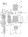
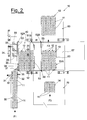
- Figures 1 and 2 are schematic plan views of a machine for the treatment of batches of objects according to the present invention, shown in two successive steps;
- Figure 3 is a schematic top side view of the machine for the treatment of batches of objects according to the present invention;
- Figure 4 schematically shows the machine object of the present invention from a front side.
- With reference to the figures, a machine for the treatment of batches of objects is shown, wholly indicated with 10, comprising feeding means 20 of
objects 11, aselection group 30 of arow 12 of objects, aformation plane 40 of abatch 13, atransfer device 50 of the formedbatch 13 and at least oneevacuation line 60 thereof towards palletisation cells, not shown. - The feeding means 20 of objects consist, for example, of a conveyor belt on which the
objects 11, or rather the packages, continually advance in the direction indicated in figure 1 with the arrow F1, arranged individually or side-by-side. - At one end of the
conveyor belt 20 theselection group 30 of arow 12 of objects is arranged, which comprises apressing device 31, able to interrupt or slow down the feeding of theobjects 11, amobile counteraction element 33 of therow 12 in formation, and aseparator device 35 with programmed variable stroke that selects the objects in variable quantity to form at least one row on aformation plane 40 of a batch, which is fixed. - The
separator device 35 comprises athrusting plane 36 for moving theselected objects 11, or rather therow 12 in a direction perpendicular to theconveyor belt 20. Thethrusting plane 36 is equipped with a work stroke and a return stroke and is schematically shown in figures 1 and 2 respectively in withdrawn rest position and in advanced thrusting position on therow 12 of objects. - A
stop element 37, which prevents anew package 11 advancing during the work stroke of thethrusting plane 36, is fixedly connected perpendicularly on the rear side of thethrusting plane 36 at an end thereof. - The
mobile counteraction element 33, controlled by amotor 34, can be moved in a programmable way for the formation of eachrow 12, in any position along theconveyor belt 20, to obtainrows 12 of objects, comprising a variable number ofobjects 11, for example from 1 to 10. - Figures 1 and 2 schematically show with a dotted and dashed line two different positions that can be taken up by the
counteraction element 33 for the formation ofrows 12 respectively comprising a greater or smaller number ofobjects 11. - The
pressing device 31 comprises a motorised pincer arranged upstream of thethrusting plane 36 for clamping apackage 11 being fed on opposite sides. - Figures 1 and 2 show the
pressing device 31 respectively withjaws 32 in open release position, and withjaws 32 in closed clamping position. - The
pressing device 31 is programmable so as to collaborate with theseparator device 35 and with thecounteraction element 33 in order to remove the pressure of theobjects 11 arranged upstream and always kept fed through an electronic minimum product level control. - Moreover, the
pressing device 31 can intervene in emergency conditions to interrupt the feeding of theobjects 11 to theseparator device 35 in the case of extraordinary interventions on themachine 10. - During normal operation, when a photocell, not shown, identifies the desired number of
packages 11 that, according to the specific programme, constitute arow 12, thepressing device 31 clasps thefirst package 11 after those forming the desired row 12 (figure 1). Then the work stroke of theseparator device 35 is started, which transfers therow 12 onto the formation plane of the batch 40 (figure 2). - Before the return stroke of the
separator device 35 has completely ended, thepressing device 31 anticipates the opening to recover the waiting time that would be connected to the inertia of the software control and of the pneumatic and mechanical actuations. The presence of thestop 37 perpendicular to thethrusting plane 36 of theseparator device 35 in any case prevents thepackage 11 released by thepressing device 31 from accidentally inserting at the shoulders of thethrusting plane 36. - The
selection group 30 is managed by a control system and forms abatch 13 on theformation plane 40, in which thebatch 13 comprises a number ofrows 12 of objects and a number ofobjects 11 for eachrow 12 that is variable by a programme. - The
transfer device 50 of thebatches 13 from theformation plane 40 to theevacuation line 60 towards the palletisation cell comprises evacuation means 57, i.e. an evacuation conveyor, arranged downstream of theformation plane 40 ofbatches 13 and a plurality of thrusters, top 51A and 51B andbottom shaft 53 arranged transversally with respect to theformation plane 40, fixed throughsupports 54 to a pair of chains. - As shown in the side view of figure 4, the transfer device comprises two pairs of
top chains bottom chains own motor - The two pairs of bottom chains are arranged at the side of the
evacuation conveyor 57, so that the two chains forming eachpair evacuation conveyor 57. - The two pairs of
top chains structure 58 arranged above theevacuation conveyor 57 and height-adjustable according to the height of thepackages 11. - The structure is supported by four
telescopic side uprights 59 that are height-adjustable through an actuation 61 (shown schematically) of the known type that transmits the movement to all of theuprights 59. - According to what is shown in figure 3, in a preferred embodiment, on each pair of
chains thrusters consecutive batches 13. - The supports 54 of the thrusters, as shown in figure 4, can be connected alternatively on interfacing sides of the contiguous chains.
- As an example, figure 4 shows, at the edge of the
structure 58, thethruster 51A fixed to the pair ofinner chains 55A that is located on the top branch of the chains and thethruster 51B fixed to the pair ofouter chains 55B that is located on the bottom branch of the chains. - Similarly, the
thruster 52A is connected on the top branch of the pair ofinner bottom chains 56A and thethruster 52B is shown on the bottom branch of the pair ofouter chains 56B. - As schematically shown in figure 3, the motorised bottom thruster thrusts the
batch 13 onto theevacuation conveyor 57 and the top thruster, having an independent motorisation, holds it on the opposite side to prevent the accidental toppling of thepackages 11. - The starting of the
evacuation conveyor 57 according to a direction perpendicular to the advancing direction of the batches by means of thetransfer device 50, schematised in figures 1 and 2 with the arrow F2, discharges thebatches 13 on thenext evacuation line 60 towards the palletisation cell, not shown. - During the summation of the times for the transfer of the
batch 13 onto theconveyor 57 and for the evacuation thereof another pair of bottom and top thrusters is positioned in order to form a new batch of packages on theformation plane 40, as schematised in figure 1, without ever interrupting the function of theselection group 30 that forms therows 12. - The presence, in the embodiment shown in the figures, of four top thrusters and four bottom thrusters, in which thrusters suitable for coming into contact with the batches in succession are mounted on different pairs of independently motorised chains allows successive batches of whatever size to be moved independently from each other.
- The position of the batch transferred onto the evacuation conveyor with respect to an axis of the latter is continuously variable and programmable according to the optimisation of the successive operations.
- The apparatus according to the present invention can also be equipped with a secondary feeding means 70, for example a motorised conveyor, which feeds products, such as
individual packages 11,rows 12,batches 13 or so-calledsacks 14 towards thetransfer device 50 in the direction of the arrow F3 on the opposite side with respect to theevacuation line 60. - Indeed, in the field of packaging of rolls of kitchen towel, the individual packages can then be packaged in a machine for putting them in a sack, according to different configurations.
- In this case bottom and top transfer thrusters can also be used as positioners of objects coming from the secondary conveyor according to the subsequent operations.
- Moreover, in a further embodiment of the apparatus according to the present invention, not shown, a second evacuation conveyor and possibly a second secondary conveyor are arranged next to the first. In this embodiment the transfer conveyor has a greater length, substantially equal to the width of the pairs of evacuation and secondary conveyors.
- The machine for the treatment of batches of objects according to the present invention has the advantage of having substantially continuous operation, in particular in terms of the feeding of the packages and the formation of batches.
- Moreover, the machine advantageously allows batches of variable size, like number of rows and number of objects per row, to be continuously formed.
- The machine for the treatment of batches of objects thus conceived can undergo numerous modifications and variations, all of which are covered by the invention; moreover, all of the details can be replaced by technically equivalent elements. In practice, the materials used, as well as the sizes, can be whatever according to the technical requirements.
Claims (13)
- Machine for the treatment of batches of objects comprising feeding means (20) of objects (11), a selection group (30) of at least one row (12) of objects, acting in a direction perpendicular to a feeding direction of said objects (11), and at least one evacuation line (60) of formed batches, characterised in that it comprises a fixed formation plane (40) of a batch (13) arranged downstream of said selection group (30) and a transfer device (50) of the formed batch from said formation plane (40) towards said at least one evacuation line (60), in which said selection group (30) comprises a counteraction element (33) of the row in formation that is mobile along said feeding means (20) and a separator device (35) with variable and programmed stroke for the selection of a variable quantity of objects (11) fed continuously to form said at least one row (12) on said formation plane (40) .
- Machine according to claim 1, characterised in that said separator device (35) comprises a thrusting plane (36) for the transfer of the selected objects (11) in a direction perpendicular to said feeding means (20), in which said thrusting plane (36) is equipped with a work stroke and a return stroke.
- Machine according to claim 2, characterised in that said separator device (35) comprises a stop element (37) perpendicular to said thrusting plane (36) fixedly connected on the rear side of said thrusting plane (36).
- Machine according to claim 1, characterised in that said mobile counteraction element (33) is controlled by a motor (34) continuously along a conveyor belt of said feeding means (20).
- Machine according to claim 1, characterised in that said selection group (30) comprises a pressing device (31) with pincers arranged upstream of said separator device (35), suitable for interrupting or slowing down the feeding of the objects (11).
- Machine according to claim 5, characterised in that said selection group (30) is managed by a control system that, once the feeding of a predetermined number of objects (11) forming a row (12) has been achieved, controls the actuation of said pressing device (31) and the work stroke of said separator device (35) and anticipates the opening of said pressing device (31) with respect to the return stroke of said separator device (35).
- Machine according to claim 1, characterised in that said transfer device (50) of the batch (13) from said formation plane (40) towards said at least one evacuation line (60) comprises a plurality of top thrusters (51A, 51B) and of bottom rollers (52A, 52B), each made up of a shaft (53) arranged transversally with respect to the formation plane (40), fixed through supports (51) respectively to pairs of top chains (55A, 55B) and pairs of bottom chains (56A, 56B).
- Machine according to claim 7, characterised in that said transfer device (50) comprises two pairs of top chains (55A, 55B) and two pairs of bottom chains (56A, 56B), in which each pair of chains is actuated by its own motor (155A, 155B, 156A, 156B) independently and programmably.
- Machine according to claim 8, characterised in that each pair of chains (55A, 55B, 56A, 56B) is equipped with two thrusters (51A, 51B, 52A, 52B).
- Machine according to claim 8, characterised in that said two pairs of bottom chains (56A, 56B) are arranged beside an evacuation conveyor (57), said two chains forming each pair (56A, 56B) being on opposite sides with respect to said evacuation conveyor (57), and in that said two pairs of top chains (55A, 55B) are housed on a structure (58) arranged above the evacuation conveyor (57) and height-adjustable according to the height of the packages.
- Machine according to claim 10, characterised in that said structure (58) is supported by four height-adjustable telescopic side uprights (59).
- Machine according to claim 7, characterised in that said supports (54) can be alternatively connected on opposite sides of said chains (55, 56).
- Machine according to claim 1, characterised in that it comprises a secondary feeding means (70) for feeding products (11, 12, 13, 14) to said transfer device (50) on the opposite side to said evacuation line (60).
Applications Claiming Priority (1)
| Application Number | Priority Date | Filing Date | Title |
|---|---|---|---|
| IT000777A ITMI20050777A1 (en) | 2005-04-29 | 2005-04-29 | MACHINE FOR THE TREATMENT OF LOTS OF OBJECTS |
Publications (2)
| Publication Number | Publication Date |
|---|---|
| EP1717170A1 true EP1717170A1 (en) | 2006-11-02 |
| EP1717170B1 EP1717170B1 (en) | 2008-05-21 |
Family
ID=36764417
Family Applications (1)
| Application Number | Title | Priority Date | Filing Date |
|---|---|---|---|
| EP06112685A Expired - Lifetime EP1717170B1 (en) | 2005-04-29 | 2006-04-18 | Machine for the treatment of batches of objects |
Country Status (5)
| Country | Link |
|---|---|
| EP (1) | EP1717170B1 (en) |
| AT (1) | ATE396130T1 (en) |
| DE (1) | DE602006001248D1 (en) |
| ES (1) | ES2308658T3 (en) |
| IT (1) | ITMI20050777A1 (en) |
Cited By (3)
| Publication number | Priority date | Publication date | Assignee | Title |
|---|---|---|---|---|
| FR2919593A1 (en) * | 2007-07-30 | 2009-02-06 | Sidel Participations | DEVICE FOR FORMING LOTS OF SUBSTANTIALLY PARALLELEPIPEDIC OBJECTS CIRCULATING ON A CONVEYOR BELT |
| NL2023356A (en) * | 2018-06-25 | 2020-01-06 | Moba Group Bv | Device and method for forming patterns of boxes |
| WO2026087570A1 (en) | 2024-10-24 | 2026-04-30 | Sidel Participations | Palletizing method and associated facility |
Families Citing this family (1)
| Publication number | Priority date | Publication date | Assignee | Title |
|---|---|---|---|---|
| DE102019115198A1 (en) * | 2019-06-05 | 2020-12-10 | Krones Aktiengesellschaft | Method and device for distributing and / or grouping containers |
Citations (5)
| Publication number | Priority date | Publication date | Assignee | Title |
|---|---|---|---|---|
| US2681171A (en) * | 1951-11-30 | 1954-06-15 | Robert E Johnson | Box loading and conveying machine |
| GB941490A (en) * | 1959-10-02 | 1963-11-13 | Hedwig Gamble | Conveyor means |
| US3708947A (en) * | 1971-04-09 | 1973-01-09 | Cozzoli Machine | Automatic tray loader |
| US5133446A (en) * | 1990-07-04 | 1992-07-28 | G. D. Societa Per Azioni | Device for the formation and transfer of groups of commodities |
| FR2750122A1 (en) * | 1996-06-19 | 1997-12-26 | Sip Condi Film Sa | Grouping appts. for cartons delivered in single file |
-
2005
- 2005-04-29 IT IT000777A patent/ITMI20050777A1/en unknown
-
2006
- 2006-04-18 AT AT06112685T patent/ATE396130T1/en not_active IP Right Cessation
- 2006-04-18 DE DE602006001248T patent/DE602006001248D1/en not_active Expired - Fee Related
- 2006-04-18 EP EP06112685A patent/EP1717170B1/en not_active Expired - Lifetime
- 2006-04-18 ES ES06112685T patent/ES2308658T3/en not_active Expired - Lifetime
Patent Citations (5)
| Publication number | Priority date | Publication date | Assignee | Title |
|---|---|---|---|---|
| US2681171A (en) * | 1951-11-30 | 1954-06-15 | Robert E Johnson | Box loading and conveying machine |
| GB941490A (en) * | 1959-10-02 | 1963-11-13 | Hedwig Gamble | Conveyor means |
| US3708947A (en) * | 1971-04-09 | 1973-01-09 | Cozzoli Machine | Automatic tray loader |
| US5133446A (en) * | 1990-07-04 | 1992-07-28 | G. D. Societa Per Azioni | Device for the formation and transfer of groups of commodities |
| FR2750122A1 (en) * | 1996-06-19 | 1997-12-26 | Sip Condi Film Sa | Grouping appts. for cartons delivered in single file |
Cited By (8)
| Publication number | Priority date | Publication date | Assignee | Title |
|---|---|---|---|---|
| FR2919593A1 (en) * | 2007-07-30 | 2009-02-06 | Sidel Participations | DEVICE FOR FORMING LOTS OF SUBSTANTIALLY PARALLELEPIPEDIC OBJECTS CIRCULATING ON A CONVEYOR BELT |
| WO2009019382A2 (en) | 2007-07-30 | 2009-02-12 | Sidel Participations | Method and device for forming batches of substantially parallelepiped objects moving on a conveyor belt |
| WO2009019382A3 (en) * | 2007-07-30 | 2009-04-30 | Sidel Participations | Method and device for forming batches of substantially parallelepiped objects moving on a conveyor belt |
| US8162130B2 (en) | 2007-07-30 | 2012-04-24 | Sidel Participations | Method and device for forming batches of substantially parallelepiped objects moving on a conveyor belt |
| CN101821180B (en) * | 2007-07-30 | 2014-11-05 | 西德尔公司 | Method and device for forming batches of substantially parallelepiped objects moving on conveyor belt |
| NL2023356A (en) * | 2018-06-25 | 2020-01-06 | Moba Group Bv | Device and method for forming patterns of boxes |
| WO2026087570A1 (en) | 2024-10-24 | 2026-04-30 | Sidel Participations | Palletizing method and associated facility |
| FR3167938A1 (en) * | 2024-10-24 | 2026-05-01 | Sidel Participations | Palletizing process and associated installation |
Also Published As
| Publication number | Publication date |
|---|---|
| ITMI20050777A1 (en) | 2006-10-30 |
| ES2308658T3 (en) | 2008-12-01 |
| ATE396130T1 (en) | 2008-06-15 |
| DE602006001248D1 (en) | 2008-07-03 |
| EP1717170B1 (en) | 2008-05-21 |
Similar Documents
| Publication | Publication Date | Title |
|---|---|---|
| EP2417029B1 (en) | Continuous motion inline feeder | |
| US5970834A (en) | Depalletizer and hopper feeder | |
| EP2691327B1 (en) | Machine for making stacks of folded paper sheets, and method for making stacks of folded paper sheets | |
| EP2021250B1 (en) | Automatic machine for making filter bags for infusion products | |
| US6092979A (en) | Method and apparatus for taking over and piling articles supplied in a plurality of rows and for conveying obtained piles of articles to a packaging line | |
| EP0962390B1 (en) | Unit and method for forming a group of products on a wrapping machine | |
| EP0860356B1 (en) | Apparatus for placing groups of products on pallets | |
| CN101516733A (en) | An apparatus and a process for forming packs and for stacking pallets with ceramic tiles, especially large-format ceramic tiles | |
| US4141442A (en) | Apparatus for separating articles into groups by weight | |
| EP1717170B1 (en) | Machine for the treatment of batches of objects | |
| EP1775222B1 (en) | Unit and method for forming packs of products for a packaging machine | |
| EP2709807B1 (en) | Device and method for removing trims from a series of products such as rolls or the like | |
| US3732969A (en) | Article group-segregating mechanism | |
| WO2018119495A1 (en) | Grouping and/or packing machine | |
| EP4674770A2 (en) | A gripper for a handling device | |
| EP3466853B1 (en) | Feeding station for feeding laminar elements into an insertion device | |
| US5308223A (en) | Package handling system | |
| EP1953090B1 (en) | A device for forming groups of products | |
| JP2022527238A (en) | A system and operating method for wrapping paper rolls. | |
| RU2097986C1 (en) | Method and apparatus for producing elongate noodle doughs | |
| EP1669309B1 (en) | Method for loading groups of products on pallets | |
| GB2255762A (en) | A conveyor system. | |
| WO2011114217A1 (en) | Device and method for separating and transporting groups of flat items | |
| US3770142A (en) | Reverse nested blank stacker | |
| JP4313976B2 (en) | Spacing method and apparatus for transferring objects, and pre-processing device for packing workpieces such as puff pastry |
Legal Events
| Date | Code | Title | Description |
|---|---|---|---|
| PUAI | Public reference made under article 153(3) epc to a published international application that has entered the european phase |
Free format text: ORIGINAL CODE: 0009012 |
|
| AK | Designated contracting states |
Kind code of ref document: A1 Designated state(s): AT BE BG CH CY CZ DE DK EE ES FI FR GB GR HU IE IS IT LI LT LU LV MC NL PL PT RO SE SI SK TR |
|
| AX | Request for extension of the european patent |
Extension state: AL BA HR MK YU |
|
| 17P | Request for examination filed |
Effective date: 20070424 |
|
| 17Q | First examination report despatched |
Effective date: 20070525 |
|
| AKX | Designation fees paid |
Designated state(s): AT BE BG CH CY CZ DE DK EE ES FI FR GB GR HU IE IS IT LI LT LU LV MC NL PL PT RO SE SI SK TR |
|
| GRAP | Despatch of communication of intention to grant a patent |
Free format text: ORIGINAL CODE: EPIDOSNIGR1 |
|
| GRAC | Information related to communication of intention to grant a patent modified |
Free format text: ORIGINAL CODE: EPIDOSCIGR1 |
|
| GRAS | Grant fee paid |
Free format text: ORIGINAL CODE: EPIDOSNIGR3 |
|
| GRAA | (expected) grant |
Free format text: ORIGINAL CODE: 0009210 |
|
| AK | Designated contracting states |
Kind code of ref document: B1 Designated state(s): AT BE BG CH CY CZ DE DK EE ES FI FR GB GR HU IE IS IT LI LT LU LV MC NL PL PT RO SE SI SK TR |
|
| REG | Reference to a national code |
Ref country code: GB Ref legal event code: FG4D |
|
| REG | Reference to a national code |
Ref country code: CH Ref legal event code: EP |
|
| REF | Corresponds to: |
Ref document number: 602006001248 Country of ref document: DE Date of ref document: 20080703 Kind code of ref document: P |
|
| REG | Reference to a national code |
Ref country code: IE Ref legal event code: FG4D |
|
| PG25 | Lapsed in a contracting state [announced via postgrant information from national office to epo] |
Ref country code: SI Free format text: LAPSE BECAUSE OF FAILURE TO SUBMIT A TRANSLATION OF THE DESCRIPTION OR TO PAY THE FEE WITHIN THE PRESCRIBED TIME-LIMIT Effective date: 20080521 |
|
| PG25 | Lapsed in a contracting state [announced via postgrant information from national office to epo] |
Ref country code: FI Free format text: LAPSE BECAUSE OF FAILURE TO SUBMIT A TRANSLATION OF THE DESCRIPTION OR TO PAY THE FEE WITHIN THE PRESCRIBED TIME-LIMIT Effective date: 20080521 |
|
| PG25 | Lapsed in a contracting state [announced via postgrant information from national office to epo] |
Ref country code: LV Free format text: LAPSE BECAUSE OF FAILURE TO SUBMIT A TRANSLATION OF THE DESCRIPTION OR TO PAY THE FEE WITHIN THE PRESCRIBED TIME-LIMIT Effective date: 20080521 Ref country code: PL Free format text: LAPSE BECAUSE OF FAILURE TO SUBMIT A TRANSLATION OF THE DESCRIPTION OR TO PAY THE FEE WITHIN THE PRESCRIBED TIME-LIMIT Effective date: 20080521 Ref country code: AT Free format text: LAPSE BECAUSE OF FAILURE TO SUBMIT A TRANSLATION OF THE DESCRIPTION OR TO PAY THE FEE WITHIN THE PRESCRIBED TIME-LIMIT Effective date: 20080521 |
|
| REG | Reference to a national code |
Ref country code: ES Ref legal event code: FG2A Ref document number: 2308658 Country of ref document: ES Kind code of ref document: T3 |
|
| PG25 | Lapsed in a contracting state [announced via postgrant information from national office to epo] |
Ref country code: IS Free format text: LAPSE BECAUSE OF FAILURE TO SUBMIT A TRANSLATION OF THE DESCRIPTION OR TO PAY THE FEE WITHIN THE PRESCRIBED TIME-LIMIT Effective date: 20080921 |
|
| PG25 | Lapsed in a contracting state [announced via postgrant information from national office to epo] |
Ref country code: SE Free format text: LAPSE BECAUSE OF FAILURE TO SUBMIT A TRANSLATION OF THE DESCRIPTION OR TO PAY THE FEE WITHIN THE PRESCRIBED TIME-LIMIT Effective date: 20080821 Ref country code: LT Free format text: LAPSE BECAUSE OF FAILURE TO SUBMIT A TRANSLATION OF THE DESCRIPTION OR TO PAY THE FEE WITHIN THE PRESCRIBED TIME-LIMIT Effective date: 20080521 Ref country code: CZ Free format text: LAPSE BECAUSE OF FAILURE TO SUBMIT A TRANSLATION OF THE DESCRIPTION OR TO PAY THE FEE WITHIN THE PRESCRIBED TIME-LIMIT Effective date: 20080521 Ref country code: DK Free format text: LAPSE BECAUSE OF FAILURE TO SUBMIT A TRANSLATION OF THE DESCRIPTION OR TO PAY THE FEE WITHIN THE PRESCRIBED TIME-LIMIT Effective date: 20080521 |
|
| PG25 | Lapsed in a contracting state [announced via postgrant information from national office to epo] |
Ref country code: BE Free format text: LAPSE BECAUSE OF FAILURE TO SUBMIT A TRANSLATION OF THE DESCRIPTION OR TO PAY THE FEE WITHIN THE PRESCRIBED TIME-LIMIT Effective date: 20080521 Ref country code: SK Free format text: LAPSE BECAUSE OF FAILURE TO SUBMIT A TRANSLATION OF THE DESCRIPTION OR TO PAY THE FEE WITHIN THE PRESCRIBED TIME-LIMIT Effective date: 20080521 Ref country code: PT Free format text: LAPSE BECAUSE OF FAILURE TO SUBMIT A TRANSLATION OF THE DESCRIPTION OR TO PAY THE FEE WITHIN THE PRESCRIBED TIME-LIMIT Effective date: 20081021 Ref country code: RO Free format text: LAPSE BECAUSE OF FAILURE TO SUBMIT A TRANSLATION OF THE DESCRIPTION OR TO PAY THE FEE WITHIN THE PRESCRIBED TIME-LIMIT Effective date: 20080521 |
|
| PLBE | No opposition filed within time limit |
Free format text: ORIGINAL CODE: 0009261 |
|
| STAA | Information on the status of an ep patent application or granted ep patent |
Free format text: STATUS: NO OPPOSITION FILED WITHIN TIME LIMIT |
|
| 26N | No opposition filed |
Effective date: 20090224 |
|
| PG25 | Lapsed in a contracting state [announced via postgrant information from national office to epo] |
Ref country code: EE Free format text: LAPSE BECAUSE OF FAILURE TO SUBMIT A TRANSLATION OF THE DESCRIPTION OR TO PAY THE FEE WITHIN THE PRESCRIBED TIME-LIMIT Effective date: 20080521 Ref country code: BG Free format text: LAPSE BECAUSE OF FAILURE TO SUBMIT A TRANSLATION OF THE DESCRIPTION OR TO PAY THE FEE WITHIN THE PRESCRIBED TIME-LIMIT Effective date: 20080821 |
|
| PGFP | Annual fee paid to national office [announced via postgrant information from national office to epo] |
Ref country code: ES Payment date: 20090508 Year of fee payment: 4 |
|
| PGFP | Annual fee paid to national office [announced via postgrant information from national office to epo] |
Ref country code: DE Payment date: 20090420 Year of fee payment: 4 Ref country code: FR Payment date: 20090417 Year of fee payment: 4 |
|
| PGFP | Annual fee paid to national office [announced via postgrant information from national office to epo] |
Ref country code: IT Payment date: 20090430 Year of fee payment: 4 |
|
| NLV4 | Nl: lapsed or anulled due to non-payment of the annual fee |
Effective date: 20091101 |
|
| REG | Reference to a national code |
Ref country code: IE Ref legal event code: MM4A |
|
| PG25 | Lapsed in a contracting state [announced via postgrant information from national office to epo] |
Ref country code: NL Free format text: LAPSE BECAUSE OF NON-PAYMENT OF DUE FEES Effective date: 20091101 |
|
| PG25 | Lapsed in a contracting state [announced via postgrant information from national office to epo] |
Ref country code: MC Free format text: LAPSE BECAUSE OF NON-PAYMENT OF DUE FEES Effective date: 20090430 Ref country code: IE Free format text: LAPSE BECAUSE OF NON-PAYMENT OF DUE FEES Effective date: 20090418 |
|
| PG25 | Lapsed in a contracting state [announced via postgrant information from national office to epo] |
Ref country code: GR Free format text: LAPSE BECAUSE OF FAILURE TO SUBMIT A TRANSLATION OF THE DESCRIPTION OR TO PAY THE FEE WITHIN THE PRESCRIBED TIME-LIMIT Effective date: 20080822 |
|
| REG | Reference to a national code |
Ref country code: CH Ref legal event code: PL |
|
| GBPC | Gb: european patent ceased through non-payment of renewal fee |
Effective date: 20100418 |
|
| REG | Reference to a national code |
Ref country code: FR Ref legal event code: ST Effective date: 20101230 |
|
| PG25 | Lapsed in a contracting state [announced via postgrant information from national office to epo] |
Ref country code: CH Free format text: LAPSE BECAUSE OF NON-PAYMENT OF DUE FEES Effective date: 20100430 Ref country code: LI Free format text: LAPSE BECAUSE OF NON-PAYMENT OF DUE FEES Effective date: 20100430 Ref country code: DE Free format text: LAPSE BECAUSE OF NON-PAYMENT OF DUE FEES Effective date: 20101103 |
|
| PG25 | Lapsed in a contracting state [announced via postgrant information from national office to epo] |
Ref country code: GB Free format text: LAPSE BECAUSE OF NON-PAYMENT OF DUE FEES Effective date: 20100418 Ref country code: IT Free format text: LAPSE BECAUSE OF NON-PAYMENT OF DUE FEES Effective date: 20100418 |
|
| PG25 | Lapsed in a contracting state [announced via postgrant information from national office to epo] |
Ref country code: LU Free format text: LAPSE BECAUSE OF NON-PAYMENT OF DUE FEES Effective date: 20090418 |
|
| PG25 | Lapsed in a contracting state [announced via postgrant information from national office to epo] |
Ref country code: HU Free format text: LAPSE BECAUSE OF FAILURE TO SUBMIT A TRANSLATION OF THE DESCRIPTION OR TO PAY THE FEE WITHIN THE PRESCRIBED TIME-LIMIT Effective date: 20081122 |
|
| REG | Reference to a national code |
Ref country code: ES Ref legal event code: FD2A Effective date: 20110711 |
|
| PG25 | Lapsed in a contracting state [announced via postgrant information from national office to epo] |
Ref country code: ES Free format text: LAPSE BECAUSE OF NON-PAYMENT OF DUE FEES Effective date: 20110629 |
|
| PG25 | Lapsed in a contracting state [announced via postgrant information from national office to epo] |
Ref country code: TR Free format text: LAPSE BECAUSE OF FAILURE TO SUBMIT A TRANSLATION OF THE DESCRIPTION OR TO PAY THE FEE WITHIN THE PRESCRIBED TIME-LIMIT Effective date: 20080521 |
|
| PG25 | Lapsed in a contracting state [announced via postgrant information from national office to epo] |
Ref country code: ES Free format text: LAPSE BECAUSE OF NON-PAYMENT OF DUE FEES Effective date: 20100419 Ref country code: CY Free format text: LAPSE BECAUSE OF FAILURE TO SUBMIT A TRANSLATION OF THE DESCRIPTION OR TO PAY THE FEE WITHIN THE PRESCRIBED TIME-LIMIT Effective date: 20080521 |
|
| PG25 | Lapsed in a contracting state [announced via postgrant information from national office to epo] |
Ref country code: FR Free format text: LAPSE BECAUSE OF NON-PAYMENT OF DUE FEES Effective date: 20100430 |