EP1716339B1 - Clamping apparatus and method - Google Patents
Clamping apparatus and method Download PDFInfo
- Publication number
- EP1716339B1 EP1716339B1 EP05723427A EP05723427A EP1716339B1 EP 1716339 B1 EP1716339 B1 EP 1716339B1 EP 05723427 A EP05723427 A EP 05723427A EP 05723427 A EP05723427 A EP 05723427A EP 1716339 B1 EP1716339 B1 EP 1716339B1
- Authority
- EP
- European Patent Office
- Prior art keywords
- planar
- clamp
- curved
- clamping apparatus
- planar surface
- Prior art date
- Legal status (The legal status is an assumption and is not a legal conclusion. Google has not performed a legal analysis and makes no representation as to the accuracy of the status listed.)
- Expired - Lifetime
Links
Images

Classifications
-
- F—MECHANICAL ENGINEERING; LIGHTING; HEATING; WEAPONS; BLASTING
- F16—ENGINEERING ELEMENTS AND UNITS; GENERAL MEASURES FOR PRODUCING AND MAINTAINING EFFECTIVE FUNCTIONING OF MACHINES OR INSTALLATIONS; THERMAL INSULATION IN GENERAL
- F16L—PIPES; JOINTS OR FITTINGS FOR PIPES; SUPPORTS FOR PIPES, CABLES OR PROTECTIVE TUBING; MEANS FOR THERMAL INSULATION IN GENERAL
- F16L3/00—Supports for pipes, cables or protective tubing, e.g. hangers, holders, clamps, cleats, clips, brackets
- F16L3/08—Supports for pipes, cables or protective tubing, e.g. hangers, holders, clamps, cleats, clips, brackets substantially surrounding the pipe, cable or protective tubing
- F16L3/10—Supports for pipes, cables or protective tubing, e.g. hangers, holders, clamps, cleats, clips, brackets substantially surrounding the pipe, cable or protective tubing divided, i.e. with two members engaging the pipe, cable or protective tubing
- F16L3/1008—Supports for pipes, cables or protective tubing, e.g. hangers, holders, clamps, cleats, clips, brackets substantially surrounding the pipe, cable or protective tubing divided, i.e. with two members engaging the pipe, cable or protective tubing with two members engaging the pipe, cable or tubing, both being made of thin band material completely surrounding the pipe
- F16L3/1025—Supports for pipes, cables or protective tubing, e.g. hangers, holders, clamps, cleats, clips, brackets substantially surrounding the pipe, cable or protective tubing divided, i.e. with two members engaging the pipe, cable or protective tubing with two members engaging the pipe, cable or tubing, both being made of thin band material completely surrounding the pipe the members being joined by quick-acting means
-
- F—MECHANICAL ENGINEERING; LIGHTING; HEATING; WEAPONS; BLASTING
- F16—ENGINEERING ELEMENTS AND UNITS; GENERAL MEASURES FOR PRODUCING AND MAINTAINING EFFECTIVE FUNCTIONING OF MACHINES OR INSTALLATIONS; THERMAL INSULATION IN GENERAL
- F16B—DEVICES FOR FASTENING OR SECURING CONSTRUCTIONAL ELEMENTS OR MACHINE PARTS TOGETHER, e.g. NAILS, BOLTS, CIRCLIPS, CLAMPS, CLIPS OR WEDGES; JOINTS OR JOINTING
- F16B2/00—Friction-grip releasable fastenings
- F16B2/02—Clamps, i.e. with gripping action effected by positive means other than the inherent resistance to deformation of the material of the fastening
- F16B2/06—Clamps, i.e. with gripping action effected by positive means other than the inherent resistance to deformation of the material of the fastening external, i.e. with contracting action
- F16B2/10—Clamps, i.e. with gripping action effected by positive means other than the inherent resistance to deformation of the material of the fastening external, i.e. with contracting action using pivoting jaws
-
- Y—GENERAL TAGGING OF NEW TECHNOLOGICAL DEVELOPMENTS; GENERAL TAGGING OF CROSS-SECTIONAL TECHNOLOGIES SPANNING OVER SEVERAL SECTIONS OF THE IPC; TECHNICAL SUBJECTS COVERED BY FORMER USPC CROSS-REFERENCE ART COLLECTIONS [XRACs] AND DIGESTS
- Y10—TECHNICAL SUBJECTS COVERED BY FORMER USPC
- Y10T—TECHNICAL SUBJECTS COVERED BY FORMER US CLASSIFICATION
- Y10T24/00—Buckles, buttons, clasps, etc.
- Y10T24/14—Bale and package ties, hose clamps
-
- Y—GENERAL TAGGING OF NEW TECHNOLOGICAL DEVELOPMENTS; GENERAL TAGGING OF CROSS-SECTIONAL TECHNOLOGIES SPANNING OVER SEVERAL SECTIONS OF THE IPC; TECHNICAL SUBJECTS COVERED BY FORMER USPC CROSS-REFERENCE ART COLLECTIONS [XRACs] AND DIGESTS
- Y10—TECHNICAL SUBJECTS COVERED BY FORMER USPC
- Y10T—TECHNICAL SUBJECTS COVERED BY FORMER US CLASSIFICATION
- Y10T24/00—Buckles, buttons, clasps, etc.
- Y10T24/14—Bale and package ties, hose clamps
- Y10T24/1457—Metal bands
Definitions
- the present invention relates generally to retaining mechanisms. More particularly, the present invention relates to a clamp that includes a top and bottom portion such that these pieces are mated at one end and pivotally connected at another.
- clamping devices that exist for retaining wires and the like for many different applications. They include cushioned and uncushioned loop clamps, hose clamps and snapper type clamps, among others.
- the loop clamp is common in the aircraft and automotive industries, for both original equipment manufacturing as well as aftermarket sectors. These clamps are often used to attach pods and splitters to the airframe.
- the cushioned clamps are sometimes used to dampen vibration.
- the typical loop clamp There are many disadvantages to the typical loop clamp.
- the clamps are difficult to install and therefore require more time and effort.
- the typical loop clamp is ergonomically undesirable in that repeated installation of the clamp results in carpal tunnel injuries for the operators.
- many loop clamps are heavy and cannot be rotated or stacked when installed.
- the fastener of FR 2 653 183 A1 comprises two components of complimentary shape capable of enclosing tubular elements, wherein one of these components comprising tongues at the first and second ends which are received in respective cut-outs in the second component, allowing the components to be clipped to the other in order to produce a quick and strong assembly.
- the FR 2 347 559 A I shows a typical hose clamp composed of two semicircular members, wherein the first top end of the top member having a tongue received in a respective cut out in the first bottom end of the bottom member.
- the EP 841 512 A1 describes top and bottom clamping members having a planar portion and a curved portion for receiving a tubular element, wherein the clamping members are movable to one another providing a hinge.
- a method and apparatus for a clamping assembly that is easy to install, ergonomically favorable, lockable, stackable, rotatable and lightweight. Moreover, it is desirable that the clamp be reused numerous times, in any type of application, without the likelihood of fatigue or failure, which also reduces cost.
- an apparatus in some embodiments allows for easy installation, is ergonomically favorable, lockable, stackable, rotatable, lightweight, inexpensive and can be used repeatedly under any application.
- a universal clamp apparatus includes two mating devices that engage at one end and pivotally connect at the other end to form a hinge.
- a method of clamping wires together, or other materials, using the universal clamp device includes affixing the clamp around the wires and locking the clamp in place, without the use of tools.
- a system for securing wires to an object includes securing the first ends of a top member and a bottom member together and pivotally connecting the second ends of the top member and the bottom member.
- FIG. 1 is a perspective view of the clamp in a closed position according to a preferred embodiment of the present invention.
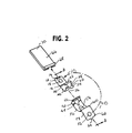
- FIG. 2 is an isometric view illustrating the unassembled clamp according to the preferred embodiment of the invention.
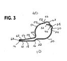
- FIG. 3 is a side view of the mated clamp assembly of the preferred embodiment of the present invention.
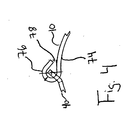
- FIG. 4 is a side view of the mated clamp assembly at the pivot point between the top and bottom clamp members according to an alternate embodiment of the present invention.
- An embodiment in accordance with the present invention provides a universal clamp that allows for easy installation, is ergonomically favorable, lockable, stackable, rotatable, lightweight, inexpensive and can be used repeatedly.
- FIG. 1 is an isometric view of the preferred embodiment of the present invention. This figure depicts the device having a bottom half clamp 10.
- the bottom half clamp 10 has a bottom planar surface 12.
- the bottom planar surface 12 has an opening 14, configured to mate or accept another device at a first planar end 15, and a second planar end 16.
- Located on the bottom planar surface 12 are edges defining an opening or a bottom planar hole 18.
- the bottom half clamp 10 has a first curved surface 20.
- the first curved surface 20 has a first curved end 22 that attaches to the second planar end 16 of the bottom planar surface 12.
- the first curved surface 20 also has an opposing second curved end 24 and a curved opening or hole 26.
- the second curved end 24 is adjacent to a second curved surface 28.
- the second curved end 24 includes a first end 30 and a flanged end 32.
- the flanged end 32 of the second curved surface 28 has a width greater than that of the second curved surface 28.
- the flanged end 32 in the preferred embodiment, forms a T-shape object to the remaining portion of the second curved surface 28.
- the bottom half clamp 10 mates with a top half clamp 40 to form the preferred embodiment of the present invention.
- the top half clamp 40 has a first curved surface 42 with a first top end 44 and a second top end 46.
- the first curved surface 42 has a top opening 48 to allow for insertion of the flanged end 32.
- the top half clamp 40 also has a second curved surface 50 with first end 52 that abuts the second top end 46 of the first curved surface 42.
- the top half clamp 40 also contains a top planar surface 58. Located on the top planar surface 58 are edges defining an opening or a top planar hole 56. A top planar end 62 of the top planar surface 58 has an extension or protrusion 64 that mates with the opening 14 of the bottom half clamp 10.
- the present invention also includes a housing 66 with a molded wedge 68 at one end, that prevents the cables or wires enclosed in the clamp from slipping out of the enclosure. Opposing the molded wedge 68 on the housing 66 is the other end 70 of the housing 66.
- the housing 66 may first be slid onto the bottom planar surface 12 and brought over the bottom half clamp 10 and the top half clamp 40 until the molded wedge 68 of the housing 66 is adjacent to the top planar surface 58. In the alternative, the housing 66 may first be slid onto the top planar surface 58 and brought over the top half clamp 40 and the bottom half clamp 10 until the housing 66 at end 70 is adjacent to the bottom planar surface 12.
- FIG. 2 illustrates the preferred embodiment of the present invention, in an unassembled position.
- This figure illustrates the bottom half clamp 10 with the opening 14 at one end.
- the bottom half clamp 10 has a bottom planar surface 12 with the second planar end 16. Located on the bottom planar surface 12 are edges defining an opening or a bottom planar hole 18.
- the second planar end 16 is connected to the first curved surface 20, which has a first curved end 22 and a second curved end 24.
- the first curved surface contains an opening or hole 26.
- the second curved end 24, adjacent to a second curved surface 28, has one end 30 which attaches to the second curved end 24 of the first curved surface 20.
- the second curved surface 28 also has a flanged end 32 that mates with the top half clamp 40.
- the top half clamp 40 has a first curved surface 42.
- the first curved surface 42 has a first top end 44.
- the first curved surface has a top opening 48 that accepts the flanged end 32 of the bottom half clamp.
- Adjacent to the first curved surface 42 is the second curved end 50.
- Located on the second curved surface 50 is an opening or hole 54.
- Adjacent the second curved surface 50 is the top planar surface 58.
- the top planar surface 58 has one end 60 and a top planar end 62 that contains a protrusion 64 that mates with the opening 14 of the bottom half clamp 10.
- This figure also depicts an optional housing 66 with its molded wedge 68 at one end that prevents the cables or wires enclosed in the clamp from slipping out of the enclosure. Opposing the molded wedge 68 on the housing 66 is the other end 70 of the housing 66.
- the housing 66 is slid onto the bottom planar surface 12 and brought over the bottom half clamp 10 and the top half clamp 40 until the molded wedge 68 of the housing 66 is adjacent to the top planar surface 58.
- the housing 66 may first be slid onto the top planar surface 58 and brought over the top half clamp 40 and the bottom half clamp 10 until the housing 66 at end 70 is adjacent to the bottom planar surface 12.
- FIG. 3 is a side view of the assembled clamp where the bottom half clamp 10 is pivotally attached to the top half clamp 40.
- the bottom half clamp has the bottom planar surface 12, with the opening 14 and the bottom planar hole 18.
- Second planar end 16 of the bottom planar surface abuts the first curved end 22 of the first curved surface 20.
- the first curved surface 20 has a second curved end 24 that attaches with end 30 of the second curved surface 28.
- Second curved surface 28 has a flanged end 32 that mates with the top half clamp 40.
- Top half clamp 40 has a first curved surface 42 with a first top end 44.
- the first curved surface 42 has a second top end 46 that lies adjacent to end 52 of the second curved surface 50.
- Located on the second curved surface 50 is a hole 54.
- Second curved surface 50 has another end 60 that attaches to the top planar surface 58.
- the top planar surface 58 has a top planar hole 56 and a top planar end 62 with the protrusion 64 that mates with the opening 14 of the bottom half clamp 10.
- the preferred embodiment of the present invention provides a device that includes a hinge, which allows for repeated use.
- This device is formed using two half clamps where the end of the first half clamp is slotted into the opening of the end of the second half of the clamp and subsequently enclosing the wires, or other suitable material.
- This aspect of the invention permits the clamp to be affixed around the wires or ducts and locked into place, without the use of any tools.
- This universal clamp responds to a need for a cost effective, easy to install replacement to the standard series of clamps available today.
- This clamp is ergonomically efficient in that it can be installed with one hand without tools. This ability to install this clamp using just one hand greatly reduces the risk of injury and makes installation time efficient.
- the use of the hinge allows the clamp to be opened and locked in place repeatedly without metal fatigue or cushion deformation. Permissive use subsequently lowers the cost of replacement parts and the costs associated with installation of the replacement parts. The ability to reuse this device also prevents the metal bands from failing due to fatigue.
- This clamp can be used to replace standard loop clamps in any type of installation and application.
- the universal loop clamp is designed to aid in the assembly of clamped components by holding itself closed and in place during installation.
- the clamp provides for installation of several clamps at one time at a single attachment point and is well suited for rapid clamp assembly and improved stacking methods for fluid lines, wire bundles, power feeder cables and fire detection lines. Easy installation not only increases productivity, it also allows for single-handed accessibility and easy clamping in hard-to-reach locations.
- the bottom half clamp 10 and top half clamp 40 represent the two metal bands of the clamp.
- the present invention is configured to mate the two clamps whereby the flanged end 32 is inserted into the top opening 48 of the top half clamp 40 to form a hinge and then engage the protrusion 64 of the top half clamp 40, with the opening 14 of the bottom half clamp 10, to close the clamp and lock it in place.
- the hinge then allows the clamp to pivot open and closed repeatedly, which prevents the metal bands from undergoing metal fatigue and later, failure.
- the cushion housing 66 may be attached to the clamp.
- the clamp locks easily, whereby the protrusion 64 of the top half clamp is engaged with the opening 14 of the bottom half clamp. This engagement can be done easily, with one hand and requires no tools of any kind. The time required for locking the clamp is minimal.
- Unlocking the clamp is just as easy and quick. Pushing the top half clamp 40 inward away from the opening 14 quickly releases the top half clamp 40 from the bottom half clamp 10. Also, wires, ducts or the like are easily removed from the clamp since the top half clamp opens widely without metal fatigue.
- top planar hole 56 of the top half clamp 40 is aligned with the bottom planar hole 18 of the bottom half clamp 10. It is through the top planar hole 56 and the bottom planar hole 18, that a fastening device such as a screw, attaches the clamp to another object such as an air frame. In this manner, several clamps can be used at once and stacked on top of each other by fastening the holes of the individual clamps together. These universal clamps can also be rotated about the fastening means by turning the clamp.
- the present invention also incorporates a difference in the thickness between the top planar surface 58 of the top half clamp 40 and the bottom planar surface 12 of the bottom half clamp 10.
- the top planar surface 58 is thicker than the bottom planar surface 12.
- the difference in thickness provides for the top planar surface to be flush with the locking mechanism, allowing the clamps to be stackable. This difference in thickness also allows for multiple pay loads to be mounted at one location.
- the slot 26 of the bottom half clamp 10 and the slot 54 of the top half clamp 40 provide yet another benefit. These slots allow the clamp to be light yet still perform well.
- the cumulative effect of using numerous lighter clamps in aircraft or automotive applications lowers the weight considerably, resulting in lower total installed weight. This results in lower cost, as well as greater maneuverability.
- the universal clamp results in cost savings in that it is lightweight, requires no tools for installation, reduces the occurrence of injuries, can be used repeatedly, and does not experience metal fatigue or failure.
- Another embodiment of this invention includes inserting flanged end 32 of the bottom half clamp 10 into the top opening 48 of the top half clamp 40 and bringing the top half clamp around whereby the top planar surface 58 of the top half clamp 40 rests approximately parallel to the bottom planar surface 12 of the bottom half clamp 10.
- This embodiment also includes inserting the protrusion 64 of the top half clamp 40 into the opening 14 of the bottom half clamp 10, locking the universal clamp.
- Another embodiment of this invention may include the further step of affixing the universal clamp to another object such as an air frame by way of inserting a fastening means such as a screw through the top planar hole 56 of the top planar surface 58, resting atop the bottom planar hole 18 of the bottom planar surface 12.
- a fastening means such as a screw
- Yet another embodiment of the invention includes a system for fastening wires or ducts to another object, such as an air frame, whereby a top member mates with a bottom member at one end and a protrusion of the top member engages with an opening of the bottom member at the other end.
- FIG. 4 is a side view of the mated clamp assembly at the pivot point between the top and bottom clamp members according to an alternate embodiment of the present invention.
- This figure discloses that that the bottom half clamp 10 is looped or curved at one end 74 such that it can be mated with the top half clamp 40.
- the looped section 76 is configured such that the top half clamp 40 is freely permitted to move about. The free movement of the looped section 76 enables the clamp to be opened and closed substantially free of interference at the pivot point.
- the top half clamp 40 includes an opening (not shown) that enables the looped section 76 of the bottom half clamp 10 to pass through it. Once the looped section 76 passes through the opening, the bottom half clamp 10 and the top half clamp are pivotally mated.
- the looped section 76 is curved back towards bottom half clamp 10 such that an entry point 78 is created. It is through this entry point 78 that the top half clamp 40 is permitted to enter and engage the bottom half clamp 10 through the opening (not shown).
- the spacing, which is created between the looped section 70 and the bottom half clamp 10, creates the entry point 78 is limited such that enables the top half clamp 40 through to engage the bottom half clamp 10 as well as prevent the top half clamp 40 from disengage from the bottom half clamp 10.
- the bottom half clamp and the top half clamp can be used interchangeable.
- the top half clamp 40 can contain the looped section 76.
Landscapes
- Engineering & Computer Science (AREA)
- General Engineering & Computer Science (AREA)
- Mechanical Engineering (AREA)
- Clamps And Clips (AREA)
- Electrical Discharge Machining, Electrochemical Machining, And Combined Machining (AREA)
- Lining Or Joining Of Plastics Or The Like (AREA)
Abstract
Description
- This application claims priority to provisional U.S. patent application entitled, UNIVERSAL CLAMP, filed February 20, 2004, having an application number
60/545,946 - The present invention relates generally to retaining mechanisms. More particularly, the present invention relates to a clamp that includes a top and bottom portion such that these pieces are mated at one end and pivotally connected at another.
- There are many clamping devices that exist for retaining wires and the like for many different applications. They include cushioned and uncushioned loop clamps, hose clamps and snapper type clamps, among others. The loop clamp is common in the aircraft and automotive industries, for both original equipment manufacturing as well as aftermarket sectors. These clamps are often used to attach pods and splitters to the airframe. The cushioned clamps are sometimes used to dampen vibration.
- There are many disadvantages to the typical loop clamp. The clamps are difficult to install and therefore require more time and effort. The typical loop clamp is ergonomically undesirable in that repeated installation of the clamp results in carpal tunnel injuries for the operators. Also, many loop clamps are heavy and cannot be rotated or stacked when installed.
- Most clamps require screws or bolts to keep the clamp locked. Others have two separate pieces that need to be locked at both ends with screws or bolts. Snapper type clamps require pliers for the installation. Thus, these all require tools for installation. The fastener of
FR 2 653 183 A1 FR 2 347 559 A EP 841 512 A1 - These clamps have a limited life in that repeated use may not be possible. The frequent removal and installation may cause fatigue on the clamp band and may lead to complete failure of the clamp. This is very undesirable especially in aircraft applications. In addition, such failures result in increased cost.
- The ability to reuse clamps is desired for many reasons. However, traditional clamps may not be reused on engines, such as aircraft turbojets, because of the immense heat cycling and vibration. The metal fatigues and the cushion deforms. Other areas where traditional clamps may not be reused include pressure lines of hydraulic systems, aircraft engine pylons and wings.
- Installing and removing wires, ducts and the like from traditional clamps can be cumbersome. Traditional loop clamp openings are not very wide and require a considerable amount of effort to be opened. Once opened, conventional loop clamps undergo metal fatigue and are subject to additional fatigue or failure when closed. In addition, the cushions that often are used with these clamps slip off or do not provide the amount of cushioning required, leading to greater abrasion and vibration.
- Accordingly, it is desirable to provide a method and apparatus for a clamping assembly that is easy to install, ergonomically favorable, lockable, stackable, rotatable and lightweight. Moreover, it is desirable that the clamp be reused numerous times, in any type of application, without the likelihood of fatigue or failure, which also reduces cost.
- The foregoing needs are met, to a great extent, by the present invention, wherein in one aspect an apparatus is provided that in some embodiments allows for easy installation, is ergonomically favorable, lockable, stackable, rotatable, lightweight, inexpensive and can be used repeatedly under any application.
- In accordance with one embodiment of the present invention, a universal clamp apparatus includes two mating devices that engage at one end and pivotally connect at the other end to form a hinge.
- In accordance with another embodiment of the present invention, a method of clamping wires together, or other materials, using the universal clamp device includes affixing the clamp around the wires and locking the clamp in place, without the use of tools.
- In accordance with yet another embodiment of the present invention, a system for securing wires to an object includes securing the first ends of a top member and a bottom member together and pivotally connecting the second ends of the top member and the bottom member.
- There has thus been outlined, rather broadly, certain embodiments of the invention in order that the detailed description may be better understood, and in order that the present contribution to the art may be better appreciated. There are, of course, additional embodiments of the invention that will be described below and which will form the subject matter of the claims appended hereto.
- In this respect, before explaining at least one embodiment of the invention in detail, it is to be understood that the invention is not limited in its application to the details of construction and to the arrangements of the components set forth in the following description or illustrated in the drawings. The invention is capable of embodiments in addition to those described and of being practiced and carried out in various ways. Also, it is to be understood that the phraseology and terminology employed herein, as well as the abstract, are for the purpose of description and should not be regarded as limiting.
- As such, those skilled in the art will appreciate that the conception upon which this disclosure is based may readily be utilized as a basis for the designing of other structures, methods and systems for carrying out the several purposes of the present invention. It is important, therefore, that the claims be regarded as including such equivalent constructions insofar as they do not depart from the spirit and scope of the present invention.
-
FIG. 1 is a perspective view of the clamp in a closed position according to a preferred embodiment of the present invention. -
FIG. 2 is an isometric view illustrating the unassembled clamp according to the preferred embodiment of the invention. -
FIG. 3 is a side view of the mated clamp assembly of the preferred embodiment of the present invention. -
FIG. 4 is a side view of the mated clamp assembly at the pivot point between the top and bottom clamp members according to an alternate embodiment of the present invention. - The invention will now be described with reference to the drawing figures, in which like reference numerals refer to like parts throughout. An embodiment in accordance with the present invention provides a universal clamp that allows for easy installation, is ergonomically favorable, lockable, stackable, rotatable, lightweight, inexpensive and can be used repeatedly.
-
FIG. 1 is an isometric view of the preferred embodiment of the present invention. This figure depicts the device having abottom half clamp 10. Thebottom half clamp 10 has a bottomplanar surface 12. The bottomplanar surface 12 has anopening 14, configured to mate or accept another device at a first planar end 15, and a secondplanar end 16. Located on the bottomplanar surface 12 are edges defining an opening or a bottomplanar hole 18. - The
bottom half clamp 10 has a firstcurved surface 20. The firstcurved surface 20 has a firstcurved end 22 that attaches to the secondplanar end 16 of the bottomplanar surface 12. The firstcurved surface 20 also has an opposing secondcurved end 24 and a curved opening orhole 26. The secondcurved end 24 is adjacent to a secondcurved surface 28. The secondcurved end 24 includes afirst end 30 and aflanged end 32. - The
flanged end 32 of the secondcurved surface 28 has a width greater than that of the secondcurved surface 28. Theflanged end 32, in the preferred embodiment, forms a T-shape object to the remaining portion of the secondcurved surface 28. - The bottom half clamp 10 mates with a top half clamp 40 to form the preferred embodiment of the present invention. The
top half clamp 40 has a firstcurved surface 42 with a firsttop end 44 and a secondtop end 46. The firstcurved surface 42 has atop opening 48 to allow for insertion of theflanged end 32. The top half clamp 40 also has a secondcurved surface 50 withfirst end 52 that abuts the secondtop end 46 of the firstcurved surface 42. - The top half clamp 40 also contains a top
planar surface 58. Located on the topplanar surface 58 are edges defining an opening or a topplanar hole 56. A topplanar end 62 of the topplanar surface 58 has an extension orprotrusion 64 that mates with theopening 14 of thebottom half clamp 10. - The present invention also includes a
housing 66 with a moldedwedge 68 at one end, that prevents the cables or wires enclosed in the clamp from slipping out of the enclosure. Opposing the moldedwedge 68 on thehousing 66 is theother end 70 of thehousing 66. Thehousing 66 may first be slid onto the bottomplanar surface 12 and brought over thebottom half clamp 10 and the top half clamp 40 until the moldedwedge 68 of thehousing 66 is adjacent to the topplanar surface 58. In the alternative, thehousing 66 may first be slid onto the topplanar surface 58 and brought over thetop half clamp 40 and the bottom half clamp 10 until thehousing 66 atend 70 is adjacent to the bottomplanar surface 12. -
FIG. 2 illustrates the preferred embodiment of the present invention, in an unassembled position. This figure illustrates the bottom half clamp 10 with theopening 14 at one end. The bottom half clamp 10 has a bottomplanar surface 12 with the secondplanar end 16. Located on the bottomplanar surface 12 are edges defining an opening or a bottomplanar hole 18. The secondplanar end 16 is connected to the firstcurved surface 20, which has a firstcurved end 22 and a secondcurved end 24. The first curved surface contains an opening orhole 26. The secondcurved end 24, adjacent to a secondcurved surface 28, has oneend 30 which attaches to the secondcurved end 24 of the firstcurved surface 20. The secondcurved surface 28 also has aflanged end 32 that mates with thetop half clamp 40. - The
top half clamp 40 has a firstcurved surface 42. The firstcurved surface 42 has a firsttop end 44. The first curved surface has atop opening 48 that accepts theflanged end 32 of the bottom half clamp. Adjacent to the firstcurved surface 42 is the secondcurved end 50. Located on the secondcurved surface 50 is an opening orhole 54. Adjacent the secondcurved surface 50 is the topplanar surface 58. The topplanar surface 58 has one end 60 and a topplanar end 62 that contains aprotrusion 64 that mates with theopening 14 of thebottom half clamp 10. - This figure also depicts an
optional housing 66 with its moldedwedge 68 at one end that prevents the cables or wires enclosed in the clamp from slipping out of the enclosure. Opposing the moldedwedge 68 on thehousing 66 is theother end 70 of thehousing 66. Thehousing 66 is slid onto the bottomplanar surface 12 and brought over thebottom half clamp 10 and the top half clamp 40 until the moldedwedge 68 of thehousing 66 is adjacent to the topplanar surface 58. In the alternative, thehousing 66 may first be slid onto the topplanar surface 58 and brought over thetop half clamp 40 and the bottom half clamp 10 until thehousing 66 atend 70 is adjacent to the bottomplanar surface 12. -
FIG. 3 is a side view of the assembled clamp where the bottom half clamp 10 is pivotally attached to thetop half clamp 40. The bottom half clamp has the bottomplanar surface 12, with theopening 14 and the bottomplanar hole 18. Secondplanar end 16 of the bottom planar surface abuts the firstcurved end 22 of the firstcurved surface 20. The firstcurved surface 20 has a secondcurved end 24 that attaches withend 30 of the secondcurved surface 28. Secondcurved surface 28 has aflanged end 32 that mates with thetop half clamp 40. - Top
half clamp 40 has a firstcurved surface 42 with a firsttop end 44. The firstcurved surface 42 has a secondtop end 46 that lies adjacent to end 52 of the secondcurved surface 50. Located on the secondcurved surface 50 is ahole 54. Secondcurved surface 50 has another end 60 that attaches to the topplanar surface 58. The topplanar surface 58 has a topplanar hole 56 and a topplanar end 62 with theprotrusion 64 that mates with theopening 14 of thebottom half clamp 10. - The preferred embodiment of the present invention provides a device that includes a hinge, which allows for repeated use. This device is formed using two half clamps where the end of the first half clamp is slotted into the opening of the end of the second half of the clamp and subsequently enclosing the wires, or other suitable material. This aspect of the invention permits the clamp to be affixed around the wires or ducts and locked into place, without the use of any tools.
- This universal clamp responds to a need for a cost effective, easy to install replacement to the standard series of clamps available today. This clamp is ergonomically efficient in that it can be installed with one hand without tools. This ability to install this clamp using just one hand greatly reduces the risk of injury and makes installation time efficient. The use of the hinge allows the clamp to be opened and locked in place repeatedly without metal fatigue or cushion deformation. Permissive use subsequently lowers the cost of replacement parts and the costs associated with installation of the replacement parts. The ability to reuse this device also prevents the metal bands from failing due to fatigue. This clamp can be used to replace standard loop clamps in any type of installation and application.
- The universal loop clamp is designed to aid in the assembly of clamped components by holding itself closed and in place during installation. The clamp provides for installation of several clamps at one time at a single attachment point and is well suited for rapid clamp assembly and improved stacking methods for fluid lines, wire bundles, power feeder cables and fire detection lines. Easy installation not only increases productivity, it also allows for single-handed accessibility and easy clamping in hard-to-reach locations.
- The
bottom half clamp 10 and top half clamp 40 represent the two metal bands of the clamp. The present invention is configured to mate the two clamps whereby theflanged end 32 is inserted into thetop opening 48 of the top half clamp 40 to form a hinge and then engage theprotrusion 64 of thetop half clamp 40, with theopening 14 of thebottom half clamp 10, to close the clamp and lock it in place. The hinge then allows the clamp to pivot open and closed repeatedly, which prevents the metal bands from undergoing metal fatigue and later, failure. - Once the two half clamps are mated to form the clamping assembly, the
cushion housing 66 may be attached to the clamp. The clamp locks easily, whereby theprotrusion 64 of the top half clamp is engaged with theopening 14 of the bottom half clamp. This engagement can be done easily, with one hand and requires no tools of any kind. The time required for locking the clamp is minimal. - Unlocking the clamp is just as easy and quick. Pushing the top half clamp 40 inward away from the
opening 14 quickly releases the top half clamp 40 from thebottom half clamp 10. Also, wires, ducts or the like are easily removed from the clamp since the top half clamp opens widely without metal fatigue. - Upon locking, the top
planar hole 56 of thetop half clamp 40 is aligned with the bottomplanar hole 18 of thebottom half clamp 10. It is through the topplanar hole 56 and the bottomplanar hole 18, that a fastening device such as a screw, attaches the clamp to another object such as an air frame. In this manner, several clamps can be used at once and stacked on top of each other by fastening the holes of the individual clamps together. These universal clamps can also be rotated about the fastening means by turning the clamp. - In a preferred embodiment, the present invention also incorporates a difference in the thickness between the top
planar surface 58 of thetop half clamp 40 and the bottomplanar surface 12 of thebottom half clamp 10. In particular, the topplanar surface 58 is thicker than the bottomplanar surface 12. The difference in thickness provides for the top planar surface to be flush with the locking mechanism, allowing the clamps to be stackable. This difference in thickness also allows for multiple pay loads to be mounted at one location. - The
slot 26 of thebottom half clamp 10 and theslot 54 of the top half clamp 40 provide yet another benefit. These slots allow the clamp to be light yet still perform well. The cumulative effect of using numerous lighter clamps in aircraft or automotive applications lowers the weight considerably, resulting in lower total installed weight. This results in lower cost, as well as greater maneuverability. Thus, the universal clamp results in cost savings in that it is lightweight, requires no tools for installation, reduces the occurrence of injuries, can be used repeatedly, and does not experience metal fatigue or failure. - Another embodiment of this invention includes inserting
flanged end 32 of the bottom half clamp 10 into thetop opening 48 of thetop half clamp 40 and bringing the top half clamp around whereby the topplanar surface 58 of thetop half clamp 40 rests approximately parallel to the bottomplanar surface 12 of thebottom half clamp 10. This embodiment also includes inserting theprotrusion 64 of the top half clamp 40 into theopening 14 of thebottom half clamp 10, locking the universal clamp. - Another embodiment of this invention may include the further step of affixing the universal clamp to another object such as an air frame by way of inserting a fastening means such as a screw through the top
planar hole 56 of the topplanar surface 58, resting atop the bottomplanar hole 18 of the bottomplanar surface 12. Yet another embodiment of the invention includes a system for fastening wires or ducts to another object, such as an air frame, whereby a top member mates with a bottom member at one end and a protrusion of the top member engages with an opening of the bottom member at the other end. -
FIG. 4 is a side view of the mated clamp assembly at the pivot point between the top and bottom clamp members according to an alternate embodiment of the present invention. This figure discloses that that the bottom half clamp 10 is looped or curved at oneend 74 such that it can be mated with thetop half clamp 40. The loopedsection 76 is configured such that thetop half clamp 40 is freely permitted to move about. The free movement of the loopedsection 76 enables the clamp to be opened and closed substantially free of interference at the pivot point. - Referring to
FIG.4 , thetop half clamp 40 includes an opening (not shown) that enables the loopedsection 76 of the bottom half clamp 10 to pass through it. Once the loopedsection 76 passes through the opening, thebottom half clamp 10 and the top half clamp are pivotally mated. - It is noted that in this alternate embodiment the looped
section 76 is curved back towards bottom half clamp 10 such that anentry point 78 is created. It is through thisentry point 78 that thetop half clamp 40 is permitted to enter and engage the bottom half clamp 10 through the opening (not shown). The spacing, which is created between the loopedsection 70 and thebottom half clamp 10, creates theentry point 78 is limited such that enables the top half clamp 40 through to engage the bottom half clamp 10 as well as prevent the top half clamp 40 from disengage from thebottom half clamp 10. - In this alternate embodiment, it is within the scope of this invention that the bottom half clamp and the top half clamp can be used interchangeable. For example, the top half clamp 40 can contain the looped
section 76. - The many features and advantages of the invention are apparent from the detailed specification, and thus, it is intended by the appended claims to cover all such features and advantages of the invention which fall within the true spirit and scope of the invention. Further, since numerous modifications and variations will readily occur to those skilled in the art, it is not desired to limit the invention to the exact construction and operation illustrated and described, and accordingly, all suitable modifications and equivalents may be resorted to, falling within the scope of the invention.
Claims (16)
- A clamping apparatus comprising:a top member (40) having a top planar surface (58) with a first top planar end (62) anda second top end (60), wherein the first top planar end (62) comprises a protrusion (64) extending therefrom, and a first top curved surface (42) with a first top end (44), wherein the first top curved surface (42) has a top opening (48);a bottom member (10) having a first bottom curved surface (20) with a first curved end (22) and a second curved end (24), and a bottom planar surface (12) with a first planar end (15) and a second planar end (16), wherein the second planar end (16) is configured to be detachably mated to the second top end (60) and the first planar end (15) is releasably attached to the top planar end (62), the bottom member (10) further comprises a slot (14) located at the first planar end (15), wherein the slot (14) mate with the protrusion (64), and a flanged end (32) extending from the second curved end (24), wherein the flanged end (32) mates with the top opening (48); anda housing (66) receiving both the first top planar end (62) of the top planar surface (58) and the first planar end (15) of the bottom planar surface (12).
- The clamping apparatus as claimed in claim 1, wherein the top planar surface (58) further comprises a top planar hole (56).
- The clamping apparatus as claimed in claim 1 or 2, wherein the bottom planar surface (12) further comprises a bottom planar hole (18).
- The clamping apparatus as claimed in claim 3, wherein the top planar hole (56) and the bottom planar hole (18) are approximately aligned upon the protrusion (64) engaging the slot (14).
- The clamping apparatus as claimed in one of the claims 1 to 4, wherein the top planar surface (58) abuts the bottom planar surface (12) upon the mating of the second planar end (16) with the second top end (60).
- The clamping apparatus as claimed in one of claims 1 to 5, wherein the top member (40) having a thickness different from the thickness of the bottom member (10).
- A clamping apparatus as claimed in claim 6, wherein the top member (40) has a thickness greater than the thickness of the bottom member (10).
- The clamping apparatus as claimed in one of claims 1 to 7, wherein the top planar surface (58) has a different thickness than the bottom planar surface (12).
- The clamping apparatus as claimed in claim 8, wherein the top planar surface (58) has a thickness greater than the thickness of the bottom planar surface (12).
- The clamping apparatus as claimed in one of claims 1 to 9, wherein the second top end (60) of the top planar surface (58) further comprises a second top curved end.
- The clamping apparatus as claimed in one of claims 1 to 10, wherein the second planar end (16) of the bottom planar surface (12) further comprises a bottom curved end.
- The clamping apparatus as claimed in one of claims 1 to 11, wherein the top member (40) having a second top curved surface, wherein the second top curved surface comprises said top slot (54) and the first bottom curved surface (20) comprises a bottom slot (26).
- The clamping apparatus as claimed in one of claims 1 to 13, wherein the bottom member (10) having a second bottom curved surface (28) adjacent the second curved end (24), the second curved surface (28) having a first end (30) adjacent the second curved end (24) and the flanged end (32).
- The clamping apparatus as claimed in one claims 1 to 13, wherein the flanged end (32) forms a T-shaped object.
- A method of clamping an object with the clamping apparatus according to claims 1 to 14 comprising:detachably engaging the protrusion (64) with the slot (14); andpivotally engaging the flanged end (32) with the top opening (48).
- A system for fastening wires to an object with a clamping apparatus according to claims 1 to 14, comprising:means for fastening the first top planar end (62) of the top member (40) to the first top planar end (15) of the bottom member (10), wherein the slot (14) located at the first planar end (15) is mated with a protrusion (64) extending from the first top planar end (62);means for pivoting connecting the first top end (44) of the top member (40) to the second curved end (24) of the bottom member (10), wherein the flanged end (32) extending from the second curved end (24) mate with the top opening (48) provided in the first top curved surface (42) adjacent the first top end (44).
Applications Claiming Priority (2)
| Application Number | Priority Date | Filing Date | Title |
|---|---|---|---|
| US54594604P | 2004-02-20 | 2004-02-20 | |
| PCT/US2005/005486 WO2005083273A1 (en) | 2004-02-20 | 2005-02-22 | Clamping apparatus and method |
Publications (2)
| Publication Number | Publication Date |
|---|---|
| EP1716339A1 EP1716339A1 (en) | 2006-11-02 |
| EP1716339B1 true EP1716339B1 (en) | 2010-04-07 |
Family
ID=34910744
Family Applications (1)
| Application Number | Title | Priority Date | Filing Date |
|---|---|---|---|
| EP05723427A Expired - Lifetime EP1716339B1 (en) | 2004-02-20 | 2005-02-22 | Clamping apparatus and method |
Country Status (6)
| Country | Link |
|---|---|
| US (1) | US7392569B2 (en) |
| EP (1) | EP1716339B1 (en) |
| AT (1) | ATE463675T1 (en) |
| DE (1) | DE602005020422D1 (en) |
| ES (1) | ES2341971T3 (en) |
| WO (1) | WO2005083273A1 (en) |
Families Citing this family (14)
| Publication number | Priority date | Publication date | Assignee | Title |
|---|---|---|---|---|
| JP2007159259A (en) * | 2005-12-05 | 2007-06-21 | Yazaki Corp | Wiring holding unit |
| US8177455B2 (en) | 2006-09-08 | 2012-05-15 | General Electric Company | Quick connect lobed fastener system |
| GB0701223D0 (en) * | 2007-01-22 | 2007-02-28 | Airbus Uk Ltd | Cable routing clip |
| US8985531B2 (en) * | 2007-03-27 | 2015-03-24 | The Boeing Company | Methods for system component installation utilizing direct manufactured components |
| US8474780B2 (en) * | 2009-04-06 | 2013-07-02 | Pelco Products, Inc. | Cable retainer for utility pole base |
| JP5519002B2 (en) * | 2009-05-07 | 2014-06-11 | アデルウィギンス グループ | Side-lock clamp device and method |
| US8714591B1 (en) | 2013-02-06 | 2014-05-06 | Honda Motor Co., Ltd. | Vehicles, net assemblies, and clampers therefor |
| US9062800B2 (en) * | 2013-04-12 | 2015-06-23 | Franklin Fastener Company | Clamp for an elongated member |
| CN103410821B (en) * | 2013-08-29 | 2016-05-11 | 浙江连翔五金科技有限公司 | A kind of pipe clamp and utilize this pipe clamp that the method for pipe fitting is installed |
| US10694732B2 (en) * | 2016-04-18 | 2020-06-30 | Safe Passage Pty Ltd | Storage device |
| DE102017103079A1 (en) * | 2017-02-15 | 2018-08-16 | Norma Germany Gmbh | clamp |
| US10753514B2 (en) * | 2017-06-20 | 2020-08-25 | Paccar Inc | Interlocking pipe support |
| JP6979601B2 (en) * | 2017-10-19 | 2021-12-15 | パナソニックIpマネジメント株式会社 | Air conditioner |
| DE102022112393A1 (en) * | 2022-05-17 | 2023-11-23 | Oetiker Schweiz Ag | V-PROFILE CLAMP WITH BAND LOCK |
Family Cites Families (20)
| Publication number | Priority date | Publication date | Assignee | Title |
|---|---|---|---|---|
| US2396925A (en) * | 1942-08-01 | 1946-03-19 | Adel Prec Products Corp | Subassembly conduit clip |
| US2655703A (en) * | 1951-10-08 | 1953-10-20 | Tinnerman Products Inc | Clamp |
| US3061253A (en) * | 1960-01-20 | 1962-10-30 | Gen Metals Corp | Line supporting clip |
| US3132402A (en) * | 1961-12-15 | 1964-05-12 | Sturdy Products Corp | Two piece clamp |
| US3376004A (en) * | 1966-06-16 | 1968-04-02 | Mc Donnell Douglas Corp | Snap clamp |
| US4029276A (en) * | 1972-08-21 | 1977-06-14 | Caterpillar Tractor Co. | Mounting bracket for tubular members |
| FR2347559A1 (en) * | 1976-04-08 | 1977-11-04 | Laine Michel | Pipe or cable grip without assembly screws - has fixing flanges on two halves turned up to form clip housing |
| US4338707A (en) * | 1980-03-10 | 1982-07-13 | Ta Mfg. Corp. | Clamp |
| EP0115246A1 (en) * | 1983-02-01 | 1984-08-08 | Hubert Combé | Pipe clamp |
| US4730800A (en) * | 1986-07-02 | 1988-03-15 | Engman Milton C | Universal tailpipe holding bracket |
| FR2634855B1 (en) * | 1988-07-26 | 1990-12-21 | Weiss Jacques | HOSE CLAMP |
| FR2653183B1 (en) * | 1989-10-12 | 1992-01-31 | Rapid Sa | CLIP FOR FIXING AN ELEMENT FOR TUBULAR EXAMPLE ON ANY WALL. |
| JP2563935Y2 (en) * | 1991-02-14 | 1998-03-04 | 株式会社ニフコ | Mounting fixture |
| GB2272724B (en) * | 1992-11-19 | 1995-09-20 | Arvin Uk Ltd | Exhaust clamp |
| US5377940A (en) * | 1993-03-19 | 1995-01-03 | Bell Helicopter Textron Inc. | Self-restraining loop clamp |
| US5497973A (en) * | 1994-01-31 | 1996-03-12 | Balzen; William H. | Theft resistant sign clamp |
| SE510015C2 (en) * | 1996-11-01 | 1999-04-12 | Isco Ab | mounting clamp |
| DE10159012A1 (en) * | 2001-11-30 | 2003-06-12 | Hilti Ag | Suspension device for elongated objects |
| US6892990B2 (en) * | 2002-04-02 | 2005-05-17 | Preformed Line Products Company | Modular cable support apparatus, method, and system |
| US6732982B1 (en) * | 2003-04-09 | 2004-05-11 | Bell Helicopter Textron, Inc. | Laterally adjustable clamp |
-
2005
- 2005-02-22 AT AT05723427T patent/ATE463675T1/en not_active IP Right Cessation
- 2005-02-22 US US11/061,742 patent/US7392569B2/en not_active Expired - Lifetime
- 2005-02-22 WO PCT/US2005/005486 patent/WO2005083273A1/en not_active Ceased
- 2005-02-22 EP EP05723427A patent/EP1716339B1/en not_active Expired - Lifetime
- 2005-02-22 DE DE602005020422T patent/DE602005020422D1/en not_active Expired - Lifetime
- 2005-02-22 ES ES05723427T patent/ES2341971T3/en not_active Expired - Lifetime
Also Published As
| Publication number | Publication date |
|---|---|
| WO2005083273A1 (en) | 2005-09-09 |
| DE602005020422D1 (en) | 2010-05-20 |
| EP1716339A1 (en) | 2006-11-02 |
| US20050188509A1 (en) | 2005-09-01 |
| US7392569B2 (en) | 2008-07-01 |
| ATE463675T1 (en) | 2010-04-15 |
| ES2341971T3 (en) | 2010-06-30 |
Similar Documents
| Publication | Publication Date | Title |
|---|---|---|
| US7392569B2 (en) | Clamping apparatus and method | |
| US8282048B2 (en) | Side-locking clamping apparatus and method | |
| KR100448556B1 (en) | A clamping device for clamping of tubes or the like | |
| US7654492B2 (en) | Wire bundle support system | |
| CA3060749C (en) | Easy lock p-clamp | |
| US20160362061A1 (en) | Strap-type vehicle-to-crossbar coupler assembly | |
| US4813105A (en) | Cable clamp | |
| US20240218943A1 (en) | Cable clamp with adjustment latches | |
| AU2019311806B2 (en) | Suspension assembly | |
| US20190226606A1 (en) | Click-in pivot hinge anchor installation | |
| US5887836A (en) | Mounting bracket assembly | |
| US11906089B2 (en) | Co-molded snap-on support base, and support system and method of using the same | |
| US12525777B2 (en) | Methods and apparatus for supporting wires in openings | |
| US20190280427A1 (en) | Hinged strain relief backshells, cable assemblies and methods for strain relief | |
| EP2798232B1 (en) | Hinge device having anti-rotation device for pivot | |
| US10711941B1 (en) | Dovetail sliding mount with movable clamp bar | |
| KR20190123613A (en) | Apparatus for fixing cable | |
| US10228011B1 (en) | Lockout device | |
| CN118477267A (en) | Beam anchor and method of using the same | |
| US20120073091A1 (en) | Circumferential clamp and latching assembly | |
| US10232451B2 (en) | Fastener for securing and cutting an object and methods relating thereto | |
| EP3267054B1 (en) | Control cable quick disconnect | |
| US6161877A (en) | Conduit interlock assembly | |
| CN215600975U (en) | Quick-release clamp | |
| CN113524090A (en) | Apparatus and method for facilitating fastening of fasteners |
Legal Events
| Date | Code | Title | Description |
|---|---|---|---|
| PUAI | Public reference made under article 153(3) epc to a published international application that has entered the european phase |
Free format text: ORIGINAL CODE: 0009012 |
|
| 17P | Request for examination filed |
Effective date: 20060821 |
|
| AK | Designated contracting states |
Kind code of ref document: A1 Designated state(s): AT BE BG CH CY CZ DE DK EE ES FI FR GB GR HU IE IS IT LI LT LU MC NL PL PT RO SE SI SK TR |
|
| DAX | Request for extension of the european patent (deleted) | ||
| 17Q | First examination report despatched |
Effective date: 20080530 |
|
| GRAP | Despatch of communication of intention to grant a patent |
Free format text: ORIGINAL CODE: EPIDOSNIGR1 |
|
| GRAS | Grant fee paid |
Free format text: ORIGINAL CODE: EPIDOSNIGR3 |
|
| GRAA | (expected) grant |
Free format text: ORIGINAL CODE: 0009210 |
|
| RIN1 | Information on inventor provided before grant (corrected) |
Inventor name: NGUYEN, KY Inventor name: SHARKEY, BRIAN Inventor name: QUANG, CHRISTOPHER |
|
| AK | Designated contracting states |
Kind code of ref document: B1 Designated state(s): AT BE BG CH CY CZ DE DK EE ES FI FR GB GR HU IE IS IT LI LT LU MC NL PL PT RO SE SI SK TR |
|
| REG | Reference to a national code |
Ref country code: GB Ref legal event code: FG4D |
|
| REG | Reference to a national code |
Ref country code: CH Ref legal event code: EP |
|
| REG | Reference to a national code |
Ref country code: IE Ref legal event code: FG4D |
|
| REF | Corresponds to: |
Ref document number: 602005020422 Country of ref document: DE Date of ref document: 20100520 Kind code of ref document: P |
|
| REG | Reference to a national code |
Ref country code: ES Ref legal event code: FG2A Ref document number: 2341971 Country of ref document: ES Kind code of ref document: T3 |
|
| REG | Reference to a national code |
Ref country code: NL Ref legal event code: VDEP Effective date: 20100407 |
|
| PG25 | Lapsed in a contracting state [announced via postgrant information from national office to epo] |
Ref country code: SI Free format text: LAPSE BECAUSE OF FAILURE TO SUBMIT A TRANSLATION OF THE DESCRIPTION OR TO PAY THE FEE WITHIN THE PRESCRIBED TIME-LIMIT Effective date: 20100407 |
|
| LTIE | Lt: invalidation of european patent or patent extension |
Effective date: 20100407 |
|
| PG25 | Lapsed in a contracting state [announced via postgrant information from national office to epo] |
Ref country code: LT Free format text: LAPSE BECAUSE OF FAILURE TO SUBMIT A TRANSLATION OF THE DESCRIPTION OR TO PAY THE FEE WITHIN THE PRESCRIBED TIME-LIMIT Effective date: 20100407 Ref country code: NL Free format text: LAPSE BECAUSE OF FAILURE TO SUBMIT A TRANSLATION OF THE DESCRIPTION OR TO PAY THE FEE WITHIN THE PRESCRIBED TIME-LIMIT Effective date: 20100407 Ref country code: SE Free format text: LAPSE BECAUSE OF FAILURE TO SUBMIT A TRANSLATION OF THE DESCRIPTION OR TO PAY THE FEE WITHIN THE PRESCRIBED TIME-LIMIT Effective date: 20100407 |
|
| PG25 | Lapsed in a contracting state [announced via postgrant information from national office to epo] |
Ref country code: FI Free format text: LAPSE BECAUSE OF FAILURE TO SUBMIT A TRANSLATION OF THE DESCRIPTION OR TO PAY THE FEE WITHIN THE PRESCRIBED TIME-LIMIT Effective date: 20100407 Ref country code: IS Free format text: LAPSE BECAUSE OF FAILURE TO SUBMIT A TRANSLATION OF THE DESCRIPTION OR TO PAY THE FEE WITHIN THE PRESCRIBED TIME-LIMIT Effective date: 20100807 Ref country code: AT Free format text: LAPSE BECAUSE OF FAILURE TO SUBMIT A TRANSLATION OF THE DESCRIPTION OR TO PAY THE FEE WITHIN THE PRESCRIBED TIME-LIMIT Effective date: 20100407 |
|
| PG25 | Lapsed in a contracting state [announced via postgrant information from national office to epo] |
Ref country code: PL Free format text: LAPSE BECAUSE OF FAILURE TO SUBMIT A TRANSLATION OF THE DESCRIPTION OR TO PAY THE FEE WITHIN THE PRESCRIBED TIME-LIMIT Effective date: 20100407 Ref country code: CY Free format text: LAPSE BECAUSE OF FAILURE TO SUBMIT A TRANSLATION OF THE DESCRIPTION OR TO PAY THE FEE WITHIN THE PRESCRIBED TIME-LIMIT Effective date: 20100505 Ref country code: GR Free format text: LAPSE BECAUSE OF FAILURE TO SUBMIT A TRANSLATION OF THE DESCRIPTION OR TO PAY THE FEE WITHIN THE PRESCRIBED TIME-LIMIT Effective date: 20100708 |
|
| PG25 | Lapsed in a contracting state [announced via postgrant information from national office to epo] |
Ref country code: DK Free format text: LAPSE BECAUSE OF FAILURE TO SUBMIT A TRANSLATION OF THE DESCRIPTION OR TO PAY THE FEE WITHIN THE PRESCRIBED TIME-LIMIT Effective date: 20100407 Ref country code: EE Free format text: LAPSE BECAUSE OF FAILURE TO SUBMIT A TRANSLATION OF THE DESCRIPTION OR TO PAY THE FEE WITHIN THE PRESCRIBED TIME-LIMIT Effective date: 20100407 Ref country code: PT Free format text: LAPSE BECAUSE OF FAILURE TO SUBMIT A TRANSLATION OF THE DESCRIPTION OR TO PAY THE FEE WITHIN THE PRESCRIBED TIME-LIMIT Effective date: 20100809 |
|
| PLBE | No opposition filed within time limit |
Free format text: ORIGINAL CODE: 0009261 |
|
| STAA | Information on the status of an ep patent application or granted ep patent |
Free format text: STATUS: NO OPPOSITION FILED WITHIN TIME LIMIT |
|
| PG25 | Lapsed in a contracting state [announced via postgrant information from national office to epo] |
Ref country code: RO Free format text: LAPSE BECAUSE OF FAILURE TO SUBMIT A TRANSLATION OF THE DESCRIPTION OR TO PAY THE FEE WITHIN THE PRESCRIBED TIME-LIMIT Effective date: 20100407 Ref country code: SK Free format text: LAPSE BECAUSE OF FAILURE TO SUBMIT A TRANSLATION OF THE DESCRIPTION OR TO PAY THE FEE WITHIN THE PRESCRIBED TIME-LIMIT Effective date: 20100407 Ref country code: CZ Free format text: LAPSE BECAUSE OF FAILURE TO SUBMIT A TRANSLATION OF THE DESCRIPTION OR TO PAY THE FEE WITHIN THE PRESCRIBED TIME-LIMIT Effective date: 20100407 Ref country code: BE Free format text: LAPSE BECAUSE OF FAILURE TO SUBMIT A TRANSLATION OF THE DESCRIPTION OR TO PAY THE FEE WITHIN THE PRESCRIBED TIME-LIMIT Effective date: 20100407 |
|
| 26N | No opposition filed |
Effective date: 20110110 |
|
| PGFP | Annual fee paid to national office [announced via postgrant information from national office to epo] |
Ref country code: IE Payment date: 20110504 Year of fee payment: 7 |
|
| PG25 | Lapsed in a contracting state [announced via postgrant information from national office to epo] |
Ref country code: MC Free format text: LAPSE BECAUSE OF NON-PAYMENT OF DUE FEES Effective date: 20110228 |
|
| REG | Reference to a national code |
Ref country code: CH Ref legal event code: PL |
|
| PG25 | Lapsed in a contracting state [announced via postgrant information from national office to epo] |
Ref country code: CH Free format text: LAPSE BECAUSE OF NON-PAYMENT OF DUE FEES Effective date: 20110228 Ref country code: LI Free format text: LAPSE BECAUSE OF NON-PAYMENT OF DUE FEES Effective date: 20110228 |
|
| REG | Reference to a national code |
Ref country code: IE Ref legal event code: MM4A |
|
| PG25 | Lapsed in a contracting state [announced via postgrant information from national office to epo] |
Ref country code: IE Free format text: LAPSE BECAUSE OF NON-PAYMENT OF DUE FEES Effective date: 20120222 |
|
| PG25 | Lapsed in a contracting state [announced via postgrant information from national office to epo] |
Ref country code: LU Free format text: LAPSE BECAUSE OF NON-PAYMENT OF DUE FEES Effective date: 20110222 |
|
| PG25 | Lapsed in a contracting state [announced via postgrant information from national office to epo] |
Ref country code: BG Free format text: LAPSE BECAUSE OF FAILURE TO SUBMIT A TRANSLATION OF THE DESCRIPTION OR TO PAY THE FEE WITHIN THE PRESCRIBED TIME-LIMIT Effective date: 20100707 Ref country code: TR Free format text: LAPSE BECAUSE OF FAILURE TO SUBMIT A TRANSLATION OF THE DESCRIPTION OR TO PAY THE FEE WITHIN THE PRESCRIBED TIME-LIMIT Effective date: 20100407 |
|
| PG25 | Lapsed in a contracting state [announced via postgrant information from national office to epo] |
Ref country code: HU Free format text: LAPSE BECAUSE OF FAILURE TO SUBMIT A TRANSLATION OF THE DESCRIPTION OR TO PAY THE FEE WITHIN THE PRESCRIBED TIME-LIMIT Effective date: 20100407 |
|
| REG | Reference to a national code |
Ref country code: FR Ref legal event code: PLFP Year of fee payment: 12 |
|
| REG | Reference to a national code |
Ref country code: FR Ref legal event code: PLFP Year of fee payment: 13 |
|
| REG | Reference to a national code |
Ref country code: FR Ref legal event code: PLFP Year of fee payment: 14 |
|
| PGFP | Annual fee paid to national office [announced via postgrant information from national office to epo] |
Ref country code: ES Payment date: 20240301 Year of fee payment: 20 |
|
| PGFP | Annual fee paid to national office [announced via postgrant information from national office to epo] |
Ref country code: DE Payment date: 20240228 Year of fee payment: 20 Ref country code: GB Payment date: 20240227 Year of fee payment: 20 |
|
| PGFP | Annual fee paid to national office [announced via postgrant information from national office to epo] |
Ref country code: IT Payment date: 20240222 Year of fee payment: 20 Ref country code: FR Payment date: 20240226 Year of fee payment: 20 |
|
| REG | Reference to a national code |
Ref country code: DE Ref legal event code: R071 Ref document number: 602005020422 Country of ref document: DE |
|
| REG | Reference to a national code |
Ref country code: ES Ref legal event code: FD2A Effective date: 20250228 |
|
| REG | Reference to a national code |
Ref country code: GB Ref legal event code: PE20 Expiry date: 20250221 |
|
| PG25 | Lapsed in a contracting state [announced via postgrant information from national office to epo] |
Ref country code: ES Free format text: LAPSE BECAUSE OF EXPIRATION OF PROTECTION Effective date: 20250223 |
|
| PG25 | Lapsed in a contracting state [announced via postgrant information from national office to epo] |
Ref country code: GB Free format text: LAPSE BECAUSE OF EXPIRATION OF PROTECTION Effective date: 20250221 |