EP1715325B1 - Verfahren und Vorrichtung zur Detektion von Gas - Google Patents
Verfahren und Vorrichtung zur Detektion von Gas Download PDFInfo
- Publication number
- EP1715325B1 EP1715325B1 EP05252479A EP05252479A EP1715325B1 EP 1715325 B1 EP1715325 B1 EP 1715325B1 EP 05252479 A EP05252479 A EP 05252479A EP 05252479 A EP05252479 A EP 05252479A EP 1715325 B1 EP1715325 B1 EP 1715325B1
- Authority
- EP
- European Patent Office
- Prior art keywords
- primary
- detector
- optical
- gas
- gas detection
- Prior art date
- Legal status (The legal status is an assumption and is not a legal conclusion. Google has not performed a legal analysis and makes no representation as to the accuracy of the status listed.)
- Expired - Lifetime
Links
- 238000001514 detection method Methods 0.000 title claims description 104
- 238000000034 method Methods 0.000 title claims description 18
- 230000005855 radiation Effects 0.000 claims description 59
- 230000003287 optical effect Effects 0.000 claims description 57
- 230000001427 coherent effect Effects 0.000 claims description 31
- 238000005259 measurement Methods 0.000 claims description 29
- 238000010521 absorption reaction Methods 0.000 claims description 18
- 238000012544 monitoring process Methods 0.000 claims description 12
- 239000013307 optical fiber Substances 0.000 claims description 6
- 230000003111 delayed effect Effects 0.000 claims description 5
- 239000007789 gas Substances 0.000 description 85
- 230000005684 electric field Effects 0.000 description 10
- 238000005286 illumination Methods 0.000 description 9
- 238000002156 mixing Methods 0.000 description 8
- 239000013078 crystal Substances 0.000 description 7
- 230000008569 process Effects 0.000 description 7
- 230000006798 recombination Effects 0.000 description 6
- 238000005215 recombination Methods 0.000 description 6
- 230000004044 response Effects 0.000 description 6
- 239000002341 toxic gas Substances 0.000 description 6
- 229910000530 Gallium indium arsenide Inorganic materials 0.000 description 5
- KXNLCSXBJCPWGL-UHFFFAOYSA-N [Ga].[As].[In] Chemical compound [Ga].[As].[In] KXNLCSXBJCPWGL-UHFFFAOYSA-N 0.000 description 5
- 230000003321 amplification Effects 0.000 description 5
- 230000008901 benefit Effects 0.000 description 5
- 238000003199 nucleic acid amplification method Methods 0.000 description 5
- 230000010287 polarization Effects 0.000 description 5
- 230000005540 biological transmission Effects 0.000 description 3
- 238000004891 communication Methods 0.000 description 3
- 230000000694 effects Effects 0.000 description 3
- 230000009467 reduction Effects 0.000 description 3
- QGZKDVFQNNGYKY-UHFFFAOYSA-N Ammonia Chemical compound N QGZKDVFQNNGYKY-UHFFFAOYSA-N 0.000 description 2
- IJGRMHOSHXDMSA-UHFFFAOYSA-N Atomic nitrogen Chemical compound N#N IJGRMHOSHXDMSA-UHFFFAOYSA-N 0.000 description 2
- 238000012935 Averaging Methods 0.000 description 2
- CURLTUGMZLYLDI-UHFFFAOYSA-N Carbon dioxide Chemical compound O=C=O CURLTUGMZLYLDI-UHFFFAOYSA-N 0.000 description 2
- RAHZWNYVWXNFOC-UHFFFAOYSA-N Sulphur dioxide Chemical compound O=S=O RAHZWNYVWXNFOC-UHFFFAOYSA-N 0.000 description 2
- 241001632004 Tetrahymena sp. SIN Species 0.000 description 2
- 239000000443 aerosol Substances 0.000 description 2
- 230000008859 change Effects 0.000 description 2
- 238000009833 condensation Methods 0.000 description 2
- 230000005494 condensation Effects 0.000 description 2
- 238000012937 correction Methods 0.000 description 2
- 239000000428 dust Substances 0.000 description 2
- 230000005670 electromagnetic radiation Effects 0.000 description 2
- 238000002474 experimental method Methods 0.000 description 2
- 238000001914 filtration Methods 0.000 description 2
- 229930195733 hydrocarbon Natural products 0.000 description 2
- 150000002430 hydrocarbons Chemical class 0.000 description 2
- 230000006872 improvement Effects 0.000 description 2
- 238000004519 manufacturing process Methods 0.000 description 2
- 238000012986 modification Methods 0.000 description 2
- 230000004048 modification Effects 0.000 description 2
- 230000009897 systematic effect Effects 0.000 description 2
- 231100000331 toxic Toxicity 0.000 description 2
- 230000002588 toxic effect Effects 0.000 description 2
- 239000004215 Carbon black (E152) Substances 0.000 description 1
- UGFAIRIUMAVXCW-UHFFFAOYSA-N Carbon monoxide Chemical compound [O+]#[C-] UGFAIRIUMAVXCW-UHFFFAOYSA-N 0.000 description 1
- RWSOTUBLDIXVET-UHFFFAOYSA-N Dihydrogen sulfide Chemical compound S RWSOTUBLDIXVET-UHFFFAOYSA-N 0.000 description 1
- KRHYYFGTRYWZRS-UHFFFAOYSA-N Fluorane Chemical compound F KRHYYFGTRYWZRS-UHFFFAOYSA-N 0.000 description 1
- 230000032683 aging Effects 0.000 description 1
- 229910052782 aluminium Inorganic materials 0.000 description 1
- 239000004411 aluminium Substances 0.000 description 1
- XAGFODPZIPBFFR-UHFFFAOYSA-N aluminium Chemical compound [Al] XAGFODPZIPBFFR-UHFFFAOYSA-N 0.000 description 1
- 229910021529 ammonia Inorganic materials 0.000 description 1
- 238000004458 analytical method Methods 0.000 description 1
- 230000003466 anti-cipated effect Effects 0.000 description 1
- 238000013459 approach Methods 0.000 description 1
- 238000000429 assembly Methods 0.000 description 1
- 230000000712 assembly Effects 0.000 description 1
- QVGXLLKOCUKJST-UHFFFAOYSA-N atomic oxygen Chemical compound [O] QVGXLLKOCUKJST-UHFFFAOYSA-N 0.000 description 1
- 230000035559 beat frequency Effects 0.000 description 1
- 238000004364 calculation method Methods 0.000 description 1
- 239000001569 carbon dioxide Substances 0.000 description 1
- 229910002092 carbon dioxide Inorganic materials 0.000 description 1
- 229910002091 carbon monoxide Inorganic materials 0.000 description 1
- 238000011109 contamination Methods 0.000 description 1
- 230000001419 dependent effect Effects 0.000 description 1
- 238000013461 design Methods 0.000 description 1
- 238000010586 diagram Methods 0.000 description 1
- 230000007613 environmental effect Effects 0.000 description 1
- 238000011156 evaluation Methods 0.000 description 1
- 239000000835 fiber Substances 0.000 description 1
- 239000002223 garnet Substances 0.000 description 1
- 229910000040 hydrogen fluoride Inorganic materials 0.000 description 1
- 230000036039 immunity Effects 0.000 description 1
- 238000002955 isolation Methods 0.000 description 1
- 230000031700 light absorption Effects 0.000 description 1
- 239000007788 liquid Substances 0.000 description 1
- 238000012423 maintenance Methods 0.000 description 1
- 239000000463 material Substances 0.000 description 1
- MVLMQGYYLCWMFP-UHFFFAOYSA-N neodymium yttrium Chemical compound [Y].[Nd] MVLMQGYYLCWMFP-UHFFFAOYSA-N 0.000 description 1
- 229910052757 nitrogen Inorganic materials 0.000 description 1
- 238000001745 non-dispersive infrared spectroscopy Methods 0.000 description 1
- 238000010606 normalization Methods 0.000 description 1
- 239000001301 oxygen Substances 0.000 description 1
- 229910052760 oxygen Inorganic materials 0.000 description 1
- 239000002245 particle Substances 0.000 description 1
- 238000005192 partition Methods 0.000 description 1
- 238000012545 processing Methods 0.000 description 1
- 230000000717 retained effect Effects 0.000 description 1
- 230000035945 sensitivity Effects 0.000 description 1
- 241000894007 species Species 0.000 description 1
- 230000003595 spectral effect Effects 0.000 description 1
- 239000007921 spray Substances 0.000 description 1
- 230000003068 static effect Effects 0.000 description 1
- 239000000126 substance Substances 0.000 description 1
- 239000004291 sulphur dioxide Substances 0.000 description 1
- 235000010269 sulphur dioxide Nutrition 0.000 description 1
- 238000012546 transfer Methods 0.000 description 1
- 238000011144 upstream manufacturing Methods 0.000 description 1
- XLYOFNOQVPJJNP-UHFFFAOYSA-N water Substances O XLYOFNOQVPJJNP-UHFFFAOYSA-N 0.000 description 1
- 230000005428 wave function Effects 0.000 description 1
Images
Classifications
-
- G—PHYSICS
- G01—MEASURING; TESTING
- G01N—INVESTIGATING OR ANALYSING MATERIALS BY DETERMINING THEIR CHEMICAL OR PHYSICAL PROPERTIES
- G01N21/00—Investigating or analysing materials by the use of optical means, i.e. using sub-millimetre waves, infrared, visible or ultraviolet light
- G01N21/17—Systems in which incident light is modified in accordance with the properties of the material investigated
- G01N21/25—Colour; Spectral properties, i.e. comparison of effect of material on the light at two or more different wavelengths or wavelength bands
- G01N21/31—Investigating relative effect of material at wavelengths characteristic of specific elements or molecules, e.g. atomic absorption spectrometry
- G01N21/35—Investigating relative effect of material at wavelengths characteristic of specific elements or molecules, e.g. atomic absorption spectrometry using infrared light
- G01N21/3504—Investigating relative effect of material at wavelengths characteristic of specific elements or molecules, e.g. atomic absorption spectrometry using infrared light for analysing gases, e.g. multi-gas analysis
-
- G—PHYSICS
- G01—MEASURING; TESTING
- G01B—MEASURING LENGTH, THICKNESS OR SIMILAR LINEAR DIMENSIONS; MEASURING ANGLES; MEASURING AREAS; MEASURING IRREGULARITIES OF SURFACES OR CONTOURS
- G01B11/00—Measuring arrangements characterised by the use of optical techniques
-
- G—PHYSICS
- G01—MEASURING; TESTING
- G01N—INVESTIGATING OR ANALYSING MATERIALS BY DETERMINING THEIR CHEMICAL OR PHYSICAL PROPERTIES
- G01N21/00—Investigating or analysing materials by the use of optical means, i.e. using sub-millimetre waves, infrared, visible or ultraviolet light
- G01N21/17—Systems in which incident light is modified in accordance with the properties of the material investigated
- G01N21/25—Colour; Spectral properties, i.e. comparison of effect of material on the light at two or more different wavelengths or wavelength bands
- G01N21/31—Investigating relative effect of material at wavelengths characteristic of specific elements or molecules, e.g. atomic absorption spectrometry
- G01N21/39—Investigating relative effect of material at wavelengths characteristic of specific elements or molecules, e.g. atomic absorption spectrometry using tunable lasers
-
- H—ELECTRICITY
- H01—ELECTRIC ELEMENTS
- H01J—ELECTRIC DISCHARGE TUBES OR DISCHARGE LAMPS
- H01J3/00—Details of electron-optical or ion-optical arrangements or of ion traps common to two or more basic types of discharge tubes or lamps
- H01J3/14—Arrangements for focusing or reflecting ray or beam
Definitions
- the present invention relates to a method and apparatus for detecting gas and finds application in the infrared detection of gases, which term also includes vapours.
- the invention especially finds application in open path gas detectors that include a transmitter unit that transmits a beam of radiation across a path in a space being monitored and a receiver unit including a detector that detects the radiation that has passed across the space.
- open path gas detector is used to cover detection apparatus irrespective of the length of the path and irrespective of whether the path is open to atmospheric conditions and/or is enclosed.
- non-dispersive infrared spectroscopy to detect hydrocarbon gases is well established. It essentially involves transmitting infrared radiation along a path in an area being monitored; the wavelength of the infrared radiation is chosen so that it is absorbed by the gas of interest (hereafter called the "target gas") but is not substantially absorbed by other gases in the atmosphere of the area being monitored. If monitoring out-of-doors, the selected wavelength ideally should not be absorbed by liquid or gaseous water (e.g. in the form of humidity, condensation, fog, rain or spray). The intensity of the radiation that has passed along the path in the area being monitored is measured and the attenuation in the intensity of the radiation gives a measure of the amount of target gas in the monitored area.
- infrared gas detectors are usually infrared radiation at a different wavelength, which ideally is a wavelength at which the target gas does not exhibit significant absorption. Radiation at more than one reference wavelength may be used; likewise more than one detection wavelength may be used.
- the ratio between the signal obtained at the wavelength(s) where the target gas does absorb (the “sample” wavelength(s)) and the signal obtained at the wavelength(s) where the target gas does not significantly absorb (the “reference” wavelength(s)) compensates for the attenuation caused by environmental conditions, since ideally the signal at the reference wavelength(s) and the signal at the sample wavelength(s) will both be affected to the same extent by any effects (other than the presence of target gas) that attenuate the radiation.
- point gas detectors which detect gas in an area close to the detector.
- toxic gas in the context of the present specification means a gas or vapour other than oxygen, nitrogen and hydrocarbons, such as hydrogen sulphide, hydrogen fluoride, ammonia, sulphur dioxide, carbon dioxide and carbon monoxide.
- point gas detectors can be electrochemical or optical.
- point gas detectors gives rise to problems since the placing of numerous detectors throughout the area is expensive. Furthermore, if a build up of target gas takes place in a region located between the detectors, it will not be detected.
- Open path gas detectors with a path length in excess of 1 metre, typically at least 10m, are also known and allow a much larger area to be monitored by a single instrument.
- open path gas detectors have been made more attractive by the ready availability at a reasonable price of tuneable laser diodes, which can be tuned to a very narrow wavelength to detect characteristic absorbency wavelengths of target toxic gases.
- the levels of toxic gas that must be detected are generally low, typically 5ppm (parts per million) and lower, e.g. 1ppm.
- the noise in the open path gas detector can be greater than the signal representing the target gas, making it very difficult to detect such low levels of toxic target gases.
- the detection signal can become indiscernible due to drift in electronic or optical components over time, variations in temperature and/or atmospheric conditions, etc.
- GB-2353591 describes an open path gas detector that uses a tuneable laser diode as a radiation source for directing a beam across a measuring path to a radiation detector in order to detect target gas within the path.
- the laser diode transmits radiation in a very narrow bandwidth, much narrower than the absorption peak of the target gas.
- the wavelength of the laser diode is scanned across the absorption band of the target gas with a frequency f.
- the intensity of the radiation transmitted also varies with the frequency f. If the atmosphere contains no target gas, the signal from the detector has a frequency that is the same as the scan frequency f. However, if there is target gas in the atmosphere, it will absorb the radiation, thereby attenuating the radiation reaching the detector so that a plot of intensity against time will have an additional frequency component of 2f.
- the 2f component (and higher harmonic components) of the signal can be determined using a phase-sensitive measuring amplifier (lock-in amplifier).
- a quotient formed from the 2f component and the 1f component can give a measure of the amount of target gas in the measuring path.
- the 1f and 2f components will be influenced in a similar manner in response to numerous attenuation conditions, for example the length of the measuring path, obscuration of the detecting beam, atmospheric scattering etc., and therefore the 2f:1f quotient is relatively unaffected by attenuation factors other than the amount of target gas in the measuring path.
- the electrical current through the laser is varied and consequently the optical output power also varies.
- the magnitude of the 1f component is necessarily large.
- the magnitude of the 2f component is a function of the gas absorption and will be small for low levels of toxic gas.
- the 2f:1f quotients are therefore very small, typically 10 -4 to 10 -6 , and the small value of this quotient is a substantial disadvantage of this technique since it is difficult to measure accurately.
- the electronic assemblies employed to drive the laser and implement the phase sensitive measuring amplifier cause harmonic distortion of the signals and may result in harmonics of the 1f component being generated, including a component at 2f. This additional 2f component will become summed with the 2f component resulting from absorption by the target gas, leading to incorrect measured target gas concentrations.
- the median value of the scanned wavelength is controlled by a feed-back circuit, as follows.
- a beam splitter is provided in the laser diode beam and part of the beam is directed along the measuring path and part is directed at an additional detection unit; a cell that holds a sample of the target gas (or some other substance having a suitable known absorption characteristic) is placed in front of the additional detection unit and so absorbs radiation at the wavelength of the target gas.
- the signal from the additional detector will show whether or not the wavelength of radiation emitted by the diode scans the absorption band of the target gas by determining the 2f:1f quotients for this feed-back beam in the same way as for the detection beam, as discussed above.
- the beam splitter provides interference fringes that can swamp the signal of the target gas, when it is present at a low concentration in the measuring path, as discussed above.
- GB-2353591 seeks to provide an optimum alignment between the transmitter unit and the receiver unit at opposite ends of the measuring path, and for this purpose suggests the use of a two-way communication link between the receiver unit and the transmitter unit for controlling the direction of the beam being transmitted towards the receiver unit.
- the transmitter unit includes steering mirrors for changing the direction of the transmitted beam; the transmitted beam is periodically scanned across an angular range and the optimum direction of the beam is determined as that at which the intensity measured by the receiver unit is greatest.
- the communication link between the receiver unit and the transmitter unit then provides feedback on the optimum position of the steering mirrors to achieve alignment.
- a method of aligning a transmitted beam of radiation with a detector in an open path gas detector comprises steering the beam in a predetermined looped pattern around the detector at a frequency f', and detecting, using the detector, the intensity of the radiation after it has traversed the path in order to generate a corresponding detector signal.
- the position of the detector with respect to the looped beam may be determined from the variation in the intensity represented by the detector signal at a frequency of f' or a harmonic of f' (e.g. 2f', 4f' etc).
- the beam is steered in a path around the detector and the signal from the detector is analysed to find the position of the detector within the path so that the beam can be brought into alignment with the detector.
- the process may be done iteratively, e.g. by using successively narrower looped paths, until alignment is achieved.
- the amplitude of the signal from the detector at a frequency f', or a harmonic of f', where f' is the frequency at which the beam is moved around the predetermined looped pattern, can be used to provide a measure of the angular distance between a central region within the loop and the detector, e.g. the angular distance between the centre of a circular loop and the detector.
- the beam may be steered in a circular or non-circular, e.g. elliptical, path; when steered in a non-circular pattern, the ratio of the amplitude of the signal at the fundamental frequency f, or a harmonic thereof, e.g. 2f', to the amplitude of the signal at a different harmonic, e.g.
- 4f' can provide a measure of the distance between a central region within the loop and the detector.
- the phase of the variation in the intensity of the signal from the detector at the frequency f, or a harmonic of f, can provide a measure of the direction of the detector with respect to a central region within the loop, e.g. the centre of a circular loop.
- WO 2004/025324 discloses a differential absorption laser radar for the measurement of gaseous species, in which a transmit portion directs a main light beam to a remote target and also provides a local oscillator beam. A receive portion receives light returned from the remote target and coherently mixes the received light with the local oscillator beam. Additionally, signal correction means extract a portion of the main light beam and direct such extracted light back into the receive portion after having introduced a frequency difference in relation to the local oscillator beam. This provides a normalisation signal and improved immunity to drift and interference.
- US-5345306 concerns apparatus for measuring spectral absorption in an opaque specimen, in which light of a specific frequency from a laser is split into two beams, one of which is transmitted by way of the specimen to a detector and the other of which is transmitted towards the detector by way of a frequency shifter. The two beams are combined at the detector, and a beat signal is produced in respect of light transmitted by the specimen whereas none occurs in respect of light scattered by the specimen.
- DE-A-4201922 discloses a means for measuring absorption of light, by an aerosol for example, in which a beam of electromagnetic radiation is passed through a beam splitter to create first and second coherent measurement beams, both of which are transmitted through a measurement zone. After the measurement zone, the two beams are passed through a Fresnel prism to create at an evaluation device an overlap in the two beams. An interference pattern is thereby produced, which is measured for determining characteristics of the aerosol.
- the present invention seeks to overcome the above problems and to provide a gas detection system which can be produced at a low cost and which can operate efficiently and reliably.
- the present invention also seeks, at least in a preferred form described below, to provide a gas detection system, which eliminates the need for a complex beam steering system and other moving parts.
- the present invention seeks to provide a gas detection system, which is suitable for application in an open path gas detector for detecting a target gas, for example a toxic gas.
- the present invention derives from the fact that superheterodyne techniques, which are commonly used in radio reception for signal isolation and detection, provide substantial performance improvements in terms of selectivity and noise reduction over direct signal detection.
- Heterodyne mixing involves adding (mixing) radio signals in an electronic device, such as an amplifier stage, having a non-linear response in order to form sum/difference frequencies.
- Equation 7 demonstrates that the output signal S will include frequencies at twice the frequency values ⁇ 1 and ⁇ 2 , as well as sum frequencies ⁇ 1 + ⁇ 2 and difference frequencies ⁇ 1 - ⁇ 2 .
- the difference frequency ⁇ 1 - ⁇ 2 is employed and effectively generates a beat frequency at a lower value than that of either the original signals.
- the first input signal S 1 is the radio carrier signal
- the frequency ⁇ 2 of the second input signal S 2 is normally varied in order to achieve tuning and ensure that the difference frequency ⁇ 1 - ⁇ 2 remains constant.
- subsequent filtering and amplification stages in the radio receiver can be designed around a known frequency, and this greatly simplifies the circuit design and enhances performance.
- the use of the difference frequency ⁇ 1 - ⁇ 2 means that such filtering and amplification stages can operate at a significantly reduced frequency by comparison with the relatively high frequency ⁇ 1 of the radio carrier signal.
- such sum and/or difference signals may be employed in a gas detection system and method in order to monitor the presence of a target gas and measure the levels of gas present.
- a gas detection system for detecting a target gas, comprising: a transmitter unit including a source of coherent radiation and capable of directing a primary beam of the coherent radiation at a wavelength absorbed by the target gas along a primary optical path across a target gas monitoring space towards a receiver unit; a beam splitter for splitting the primary beam to generate a secondary beam of the coherent radiation; the receiver unit receiving the primary and the secondary beams of coherent radiation and having a measuring detector for providing a measurement output; and an optical element provided before the receiver unit for directing the primary and the secondary beams of radiation at the measuring detector, wherein the measuring detector comprises a detector surface on which the beams are incident with interference, and means for detecting the interference and for providing a measurement output based on said detection; characterised by a scanning device adapted to scan the wavelength of the output of the source of coherent radiation over a gas absoprtion range being detected; and means for directing the secondary beam towards the receiver unit along a further optical path so
- a method of gas detection for detecting a target gas comprising: providing a transmitter unit including a source of coherent radiation; directing a primary beam of the coherent radiation at a wavelength absorbed by the target gas along a primary optical path across a target gas monitoring space towards a receiver unit; splitting the primary beam to generate a secondary beam of the coherent radiation; passing the primary and the secondary beams of radiation through an optical element for directing the beams to the receiver unit; receiving the beams at the receiver unit with intereference; and detecting the interference at a detector surface of a measuring detector to provide a measuring output; and characterised by scanning the wavelength of the output of the source of coherent radiation to scan the primary beam over a gas absorption range being detected; directing the secondary beam towards the receiver unit along a further optical path so that the secondary beam is delayed by comparison with the primary beam; producing a combined beam by means of the optical element, in which there is a divergence between the primary beam and the secondary beam, whereby the wavelength scan
- the present invention thus makes use of a feature that has hitherto been considered to be problematic and undesirable in gas detectors, namely it specifically creates and detects interference fringes for measurement purposes.
- the present invention has a number of significant advantages.
- the need for a complex alignment and/or steering system involving moving parts is avoided, and hence manufacturing costs should be significantly reduced.
- the interference fringes can be generated and satisfactorily measured without the need for arrangements involving moving parts and feedback circuitry for driving and aligning the optical beam from the transmitter unit.
- the secondary beam may be transmitted along the further optical path by means of an optical fibre light guide.
- the difference in frequency between the primary beam and the secondary beam when combined may be precisely controlled.
- control of the combined beam may be achieved by the provision of a control arrangement for adjusting the overlap of the primary beam and the secondary beam at the measuring detector of the receiver unit.
- Such adjustment may be achieved, for example, by variation of the focus of at least one of the primary beam and the secondary beam at the measuring detector, or by adjusting the position of the measuring detector.
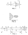
- a coherent source of light such as a laser 10
- a diverging lens 12 is arranged to transmit a beam of light through a diverging lens 12 towards a partition 14 having two slits 16 disposed within the circumference of the divergent beam.
- Light passing through the two slits 16 creates two paths of illumination directed at a screen 18.
- a pattern of illumination having peaks and troughs of intensity is created, as shown in Figure 2 .
- Figure 3 is a representation of an open path gas detector according to the invention having a transmitter unit 26 and a receiver unit 28.
- the transmitter unit 26 includes a coherent source of light in the form of a laser 30, which transmits a coherent detection beam 32 across a target gas monitoring space 34 to the receiver unit 28.
- the detection beam 32 emitted by the laser 30 is passed through a beam expander 38 comprising a pair of lenses 40, 42 and into the monitoring space 34.
- the receiver unit 28 on the far side of the monitoring space 34 includes a measuring detector 35 having a detection screen 36, and the detection screen 36 is disposed generally perpendicular to the detection beam 32.
- a first beam splitter 44 is arranged in the path of the detection beam 32, between the beam expander 38 and the monitoring space 34, in order to split the detection beam to generate a secondary beam 46 of coherent light, which is reflected along a further optical path towards the detection screen 36 of the receiver unit 28 by way of a pair of mirrors 48, 50 and a further beam splitter 52.
- the beam splitter 52 is disposed in the optical path of the detection beam 32 so that the detection beam and the secondary beam are recombined prior to illuminating the detection screen 36.
- the detection beam 32 and the secondary beam 46 are not precisely aligned on recombination but diverge at an angle ⁇ , for reasons which are discussed below.
- E y E g ⁇ sin ⁇ t + E s ⁇ sin ⁇ t + 2 ⁇ ⁇ . y . sin ⁇ / ⁇
- Equation 10 The intensity of the illumination at position y of the detection screen 36 is given by E y 2 . From Equation 10, it is evident that the equation for E y 2 will include sum and difference frequency terms representing alternate bands of bright and dark illumination in the direction y on the detecting screen 36, ie interference fringes.
- interference fringes of substantial spacing capable of being detected by a relatively small detector of, for example, 0.3 mm diameter can be generated if the angle ⁇ , at which the detection beam and the secondary beam are recombined, is kept relatively small, for example less than or equal to 0.2 degrees.
- the mixing process is performed in a suitable optical crystal that has the required non-linear polarisation properties.
- a light beam of an invisible infrared (IR) wavelength of 1064nm from the laser is converted to light of a very visible green wavelength of 532nm within the crystal.
- the green light is normally clearly visible because of slight scattering by imperfections within the crystal or by dust etc. on the surface of the crystal. Further, the green light beam is also visible (for high power lasers) within the air beyond the crystal because of dust particles that similarly scatter some of the radiation.
- the invisible IR output of the laser into the crystal is directed the invisible IR output of the laser, and out of the crystal emerges a combined beam containing not only the residual IR light but also the clearly visible radiation of double the wavelength.
- This visible beam can be separated from the residual IR radiation by using a suitable wavelength dependent filter for example; it is a real beam of electromagnetic radiation entirely separate from, and independent of, the original IR radiation.
- radiation of around 1600nm wavelength (so about 2X10 14 Hz frequency) is employed.
- This is readily detected by the use of indium gallium arsenide (InGaAs) detectors that typically have a peak response around 1500nm, although some response is also retained for lower wavelengths.
- the difference frequency that is generated will, however, generally be much smaller than 10 14 Hz, typically being of the order a few megahertz.
- Such a frequency has wavelength of the order of tens of metres and as such would not be detected by an InGaAs detector.
- a suitable detector would be a length of wire (an aerial).
- the detector 35 at the detector screen 36 thus detects the moving fringe pattern, in which the rate of movement is ⁇ 1 - ⁇ 2 .
- the detection of interference fringes offers a number of advantages by comparison with the direct measurement of the detection beam 32 alone.
- the measurement signal output by the detector 35 is less susceptible to atmospheric factors that attenuate the detection beam 32 than in the case of direct measurement of this beam. Consequently, the effect of noise generated within the detector 35 or the subsequent electronic amplification stages becomes less of a problem.
- E g is taken as the electric field vector for the detection beam which is transmitted directly from the laser 30 through the monitoring space 34 to the detection screen 36 and which is subjected to potential gas absorption
- E s as the electric field vector for the secondary or indirect beam transmitted from the laser 30 to the detection screen 36
- the electric field vector E g will be significantly less than the electric field vector E s because of the attenuation due to the gas absorption.
- the magnitude of the combined electric vector as measured at a bright band (or peak) of the interference fringe pattern is given by E s + E g
- the magnitude at a dark band (or trough) is given by E s - E g .
- P min E s - E g / k 2
- Equation 17 indicates that the perceived variation is reduced by a factor of 2, but this is a very small penalty to pay compared with the substantial advantage offered by the presence of the square root term.
- the detector 35 is an indium gallium arsenide (InGaAs) device, which offers a good noise performance and has a typical Noise Equivalent Power (NEP) of the order of 2 ⁇ 10 -11 for a typical signal bandwidth of 1MHz. It is also assumed that the measurement path is 50 metres, and the laser beam has a divergence of one degree.
- the laser power output is typically 0.5 mw for a vertical cavity surface emitting laser (VCSEL), and may be increased by a factor of 10 if a distributed feedback laser (DFB) is used instead.
- VCSEL vertical cavity surface emitting laser
- DFB distributed feedback laser
- the optical efficiency represents a realistic estimate of the total power transmitted through all the various optical elements of both the transmitter unit and the receiver unit based on the detection beam, although the actual efficiency may be marginally greater than this.
- the geometric efficiency relates to the requirement to expand the laser beam to a reasonable divergence in order to provide tolerance to pointing errors and vibration.
- the factor given in Table 2 assumes a beam divergence of 1 degree in the detection beam, in order to compensate for possible pointing errors in the transmitter unit, and collecting optics of 3cm diameter.
- the atmospheric transmission is the anticipated "worst case" that must be tolerated by the instrument.
- the collected power for the detection beam for these values is about 10 times the detector NEP level.
- the output signal from the detector will have a signal to noise (S/N) ratio given by (P max - P min )/NEP. It will be seen that this is 20,000, which is 2,000 times greater than for the direct detection beam alone.
- the actual noise level that may be achieved depends on the averaging time over which the detector signals are sampled and on the laser scanning rate. In addition, it is not the detector noise level that limits the performance of the detection system but rather the noise generated by the first stage of signal amplification performed on the output signal from the detector 35.
- amplification is performed by a transimpedance amplifier, which may yield a reduction in performance due to noise of the order of 20 times. Allowing for such reduction would reduce the S/N ratio to 1,000. Taking averaging into account as well yields a final S/N ratio of the order of 550,000, which is clearly more than adequate to achieve a final S/N ratio of 100,000 that is considered to be acceptable.
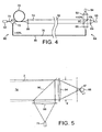
- the second embodiment of the invention includes a transmitter unit 60 including a laser 62, and a receiver unit 64 including a measurement detector 66 having a detection screen 68.
- the output from the laser 62 is supplied into an optical fibre guide 70 and thence to a beam splitter 72 where the light beam is split into a detection beam 74 and a secondary beam 76.
- the detection beam 74 is transmitted by way of an optical delay provided by a further optical fibre guide 78 to a beam expander 80 and thence across the area 82 to be monitored to a condenser 84 for focussing the detection beam on the detection screen 68 of the measurement detector 66.
- the secondary beam 76 is transmitted by way of a further fibre optical guide 86 to a beam expander 88 which directs the secondary beam 76 at a beam splitter 90 for directing a substantial proportion, amounting to approximately 90% of the secondary beam 76, to the condenser 84 and thence onto the detection screen 68.
- the remaining proportion of approximately 10% of the secondary beam 76 is transmitted through the beam splitter 90 to another condenser 92 and a reference detector 94 for use as a normalizing reference for compensating for systematic variations in the output of the laser 62.
- the detection beam 74 some of which is absorbed by traces of gas in the monitoring area 82, and the secondary beam 76 are combined downstream of the beam splitter 90 and generate interference fringes on the detection screen 68 of the measurement detector 66.
- This combined signal is detected by means of the measurement detector 66 to provide a measurement signal as output as described above.
- the laser output is scanned across the absorption band of the target gas being monitored, and the difference in path length between that of the detection beam 74 and that of the secondary beam 76 would normally introduce a time delay into the secondary beam 76 on recombination.
- two beams do not overlap on the detection screen 68 and, hence no interference fringes are generated.
- a possible way of remedying this situation is to move the measurement detector 66 towards the converging lens 84, for example, to the plane f-f'.
- the detection beam 74 and the secondary beam 76 will again overlap, although the relative spacing of the interference fringes will be reduced. In other words, the number of fringes on the detection screen 68 will be increased. It follows that the fringe intensity range separating the bright and dark bands of the fringe pattern will also be reduced and the detection sensitivity will need to be increased.
- An alternative approach to resolving this problem is to introduce a focussing arrangement into one or both of the detection beam 74 and the secondary beam 76, in order to ensure that whilst one beam is brought to a precise focus at the detection screen 68 of the measurement detector 66 the other beam is brought to an imperfect focus so as to fill the whole area of the detector screen 68.
- this might be achieved by an arrangement permitting movement of the end of the optical guide 86 and/or movement of the beam expander 88.
- the detection beam 74 and the secondary beam 76 are sufficiently aligned on recombination to ensure that a fringe pattern having a large fringe spacing is generated by comparison with the size of the detection screen 68.
- Table 1 above demonstrates that the relative angle of the two beams on recombination should preferably be of the order 0.1 degrees. This angle is relatively unaffected by pointing errors or vibrations at the transmitter unit 60, providing that the extent of such variations is less than the angle of the laser beam divergence (ie less than + or - 0.5 degrees in the example given).
- the beam splitter 90 and the converging lens 84 are fixed relative to one another in the receiver unit 64, and the light from the secondary beam 76 reflected by the beam splitter 90 and directed through the converging lens 84 is focussed on the detector screen 68 at the point x1.
- the detection beam 74 will be received within the receiver unit 64 along the path indicated by solid lines and will coincide with the secondary beam 76 on recombination and be focussed on the detector screen 68 at the same point x1.
- the detection beam 74 will appear to be travelling in the direction indicated by the dashed lines and will be focussed on the detection screen 68 at a point x2. It can be seen that in this instance the light paths of the
- the provision of the reference detector 94 for deriving a reference signal from the secondary beam 76 may be omitted altogether.
- the reference signal may be taken from the secondary beam 76 at a different location, for example upstream of the beam splitter 90 rather than downstream as illustrated.
- the described method and apparatus provide a sensitive means for detecting gas using an open path gas detector and offer substantial advantages in terms of tolerance to foggy conditions and opaque atmospheres.
Landscapes
- Physics & Mathematics (AREA)
- Spectroscopy & Molecular Physics (AREA)
- General Physics & Mathematics (AREA)
- Health & Medical Sciences (AREA)
- Life Sciences & Earth Sciences (AREA)
- Chemical & Material Sciences (AREA)
- Analytical Chemistry (AREA)
- Biochemistry (AREA)
- General Health & Medical Sciences (AREA)
- Immunology (AREA)
- Pathology (AREA)
- Optics & Photonics (AREA)
- Investigating Or Analysing Materials By Optical Means (AREA)
Claims (16)
- Gasdetektionssystem zur Detektion eines Zielgases mit:einer Sendeeinheit (26, 60), die eine Quelle (30, 62) für kohärente Strahlung enthält und in der Lage ist, einen Primärstrahl (32, 74) der kohärenten Strahlung mit einer Wellenlänge, die durch das Zielgas absorbiert wird, entlang eines primären Strahlengangs durch einen Zielgas-Überwachungsraum (34, 82) in Richtung auf eine Empfangseinheit zu lenken;einem Strahlteiler (44, 72) zur Teilung des Primärstrahls für die Erzeugung eines Sekundärstrahls (46, 76) der kohärenten Strahlung;wobei die Empfangseinheit für den Empfang des Primär- und Sekundärstrahls der kohärenten Strahlung ausgelegt ist und einen Messdetektor (35, 66) zum Vorsehen einer Messwertausgabe aufweist; undeinem optischen Element (52, 90), das vor der Empfangseinheit zum Lenken des primären und sekundären Strahlungsbündels auf den Messdetektor vorgesehen ist, wobei der Messdetektor eine Detektorfläche (36, 68), auf der der primäre und sekundäre Strahl mit Interferenz einfällt, und Mittel zum Detektieren der Interferenz und zum Vorsehen einer Messwertausgabe auf Basis der Detektion aufweist;gekennzeichnet durch:eine Abtastvorrichtung, die zum Abtasten der Wellenlänge von dem Ausgang der Quelle der kohärenten Strahlung über einen Gasabsorptionsbereich, der detektiert wird, ausgelegt ist; undMittel (48, 50; 86) zum Richten des Sekundärstrahls entlang eines weiteren Strahlengangs in Richtung auf die Empfängereinheit derart, dass der Sekundärstrahl im Vergleich zum Primärstrahl verschoben ist; und wobei:das optische Element einen optischen Strahlvereiniger (52, 90) aufweist, der den Primärstrahl und den Sekundärstrahl zu einem kombinierten Strahl vereinigt und der in dem kombinierten Strahl eine Divergenz zwischen der kohärenten Strahlung von dem Primärstrahl und der kohärenten Strahlung von dem Sekundärstrahl generiert, wobei die Wellenlängenabtastung und die Verschiebung zwischen den Strahlengängen an der Detektoroberfläche ein bewegtes Muster von Interferenzstreifen erzeugt; unddas Detektionsmittel das bewegliche Muster der Interferenzstreifen zum Vorsehen der Messwertausgabe detektiert.
- Gasdetektionssystem nach Anspruch 1, dadurch gekennzeichnet, dass die Sendeeinheit einen Laser (30, 62) aufweist.
- Gasdetektionssystem nach Anspruch 1 oder 2, dadurch gekennzeichnet, dass der weitere Strahlengang mindestens teilweise durch ein Lichtleitfaserkabel (86) zur Übertragung des Sekundärstrahls zum optischen Strahlvereiniger festgelegt ist.
- Gasdetektionssystem nach einem der vorangehenden Ansprüche, dadurch gekennzeichnet, dass eine optische Verschiebung (78) in dem primären Strahlengang enthalten ist.
- Gasdetektionssystem nach Anspruch 4, dadurch gekennzeichnet, dass die optische Verschiebung eine Länge der optischen Faser umfasst.
- Gasdetektionssystem nach einem der vorangehenden Ansprüche, ferner gekennzeichnet durch einen Referenzdetektor (94) zur Detektion eines Referenzsignals, das vom Sekundärstrahl abgeleitet ist.
- Gasdetektionssystem nach einem der vorangehenden Ansprüche, ferner gekennzeichnet durch eine Steuer-/Regel-Anordnung zum Einstellen der Überlappung von Primärstrahl und Sekundärstrahl am Messdetektor.
- Gasdetektionssystem nach Anspruch 7, dadurch gekennzeichnet, dass die Steuer-/Regel-Anordnung eingerichtet ist zur Einstellung eines der Parameter: Fokus von mindestens einem von dem Primärstrahl und dem Sekundärstrahl am Messdetektor, Position von einem optischen Element (86, 88) des weiteren Strahlengangs, und Position des Messdetektors.
- Gasdetektionssystem nach einem der vorangehenden Ansprüche, dadurch gekennzeichnet, dass der Ablenkungswinkel zwischen dem Primärstrahl und dem Sekundärstrahl kleiner oder gleich 0,2 Grad ist.
- Verfahren zur Gasdetektion, für das Detektieren eines Zielgases, umfassend:Vorsehen einer Sendeeinheit (26, 60), die eine Quelle (30, 62) für kohärente Strahlung enthält;Lenken eines Primärstrahls der kohärenten Strahlung mit einer Wellenlänge, die durch das Zielgas absorbiert wird, entlang eines primären Strahlengangs durch einen Zielgas-Überwachungsraum (34, 82) in Richtung auf eine Empfängereinheit (28, 64);Teilen des Primärstrahls zur Erzeugung eines Sekundärstrahls der kohärenten Strahlung;Hindurchführen des primären und der sekundären Strahlenbündels durch ein optisches Element für das Lenken der Strahlen zur Empfängereinheit;Empfangen der Strahlen mit Interferenz an der Empfängereinheit; undDetektieren der Interferenz an der Detektorfläche eines Messdetektors zum Vorsehen einer Messwertausgabe;und gekennzeichnet durch:Abtasten der Wellenlänge von dem Ausgang der Quelle der kohärenten Strahlung zum Abtasten des Primärstrahls über einen Gasabsorptionsbereich, der detektiert wird;Richten des Sekundärstrahls entlang eines weiteren Strahlengangs in Richtung auf die Empfängereinheit derart, dass der Sekundärstrahl im Vergleich zum Primärstrahl verschoben ist;Erzeugen eines kombinierten Strahls mittels des optischen Elements, in dem eine Divergenz zwischen dem Primärstrahl und dem Sekundärstrahl vorliegt, wobei die Wellenlängenabtastung und die Verschiebung zwischen den Strahlengängen an der Detektorfläche ein bewegtes Muster von Interferenzstreifen erzeugt; undDetektieren des bewegten Musters der Interferenzstreifen zum Vorsehen der Messwertausgabe.
- Gasdetektionsverfahren nach Anspruch 10, ferner gekennzeichnet durch den Einsatz eines Lichtleitfaserkabels (78) zum Senden des Sekundärstrahls über den weiteren Strahlengang.
- Gasdetektionsverfahren nach Anspruch 10 oder 11, ferner gekennzeichnet durch das Einführen einer optischen Verschiebung in den primären Strahlengang.
- Gasdetektionsverfahren nach einem der Ansprüche 10 bis 12, ferner gekennzeichnet durch das Detektieren eines Referenzsignals, das aus dem Sekundärstrahl abgeleitet ist.
- Gasdetektionsverfahren nach einem der Ansprüche 10 bis 13, ferner gekennzeichnet durch das Steuern/Regeln der Überlappung von Primärstrahl und Sekundärstrahl am Messdetektor (35, 66) zum Detektieren der Interferenzstreifen.
- Gasdetektionsverfahren nach Anspruch 14, gekennzeichnet durch das Steuern/Regeln der Überlappung durch das Einstellen des Fokus von mindestens einem von Primärstrahl und Sekundärstrahl, das Einstellen der Position eines optischen Elements (86, 88) des weiteren Strahlengangs, oder das Einstellen der Position des Messdetektors.
- Gasdetektionsverfahren nach einem der Ansprüche 10 bis 15, gekennzeichnet durch das Steuern/Regeln des Divergenzwinkels zwischen dem Primärstrahl und dem Sekundärstrahl auf einen Wert, der kleiner oder gleich 0,2 Grad ist.
Priority Applications (6)
| Application Number | Priority Date | Filing Date | Title |
|---|---|---|---|
| DE602005021857T DE602005021857D1 (de) | 2005-04-20 | 2005-04-20 | Verfahren und Vorrichtung zur Detektion von Gas |
| EP05252479A EP1715325B1 (de) | 2005-04-20 | 2005-04-20 | Verfahren und Vorrichtung zur Detektion von Gas |
| PCT/GB2006/001380 WO2006111717A1 (en) | 2005-04-20 | 2006-04-13 | Method and apparatus for the detection of gas |
| KR1020077023573A KR20070121749A (ko) | 2005-04-20 | 2006-04-13 | 가스검출방법과 장치 |
| JP2008507150A JP2008537138A (ja) | 2005-04-20 | 2006-04-13 | ガス検出方法及び装置 |
| NO20075915A NO20075915L (no) | 2005-04-20 | 2007-11-16 | Fremgangsmate og anordning for gassdeteksjon |
Applications Claiming Priority (1)
| Application Number | Priority Date | Filing Date | Title |
|---|---|---|---|
| EP05252479A EP1715325B1 (de) | 2005-04-20 | 2005-04-20 | Verfahren und Vorrichtung zur Detektion von Gas |
Publications (2)
| Publication Number | Publication Date |
|---|---|
| EP1715325A1 EP1715325A1 (de) | 2006-10-25 |
| EP1715325B1 true EP1715325B1 (de) | 2010-06-16 |
Family
ID=34940948
Family Applications (1)
| Application Number | Title | Priority Date | Filing Date |
|---|---|---|---|
| EP05252479A Expired - Lifetime EP1715325B1 (de) | 2005-04-20 | 2005-04-20 | Verfahren und Vorrichtung zur Detektion von Gas |
Country Status (6)
| Country | Link |
|---|---|
| EP (1) | EP1715325B1 (de) |
| JP (1) | JP2008537138A (de) |
| KR (1) | KR20070121749A (de) |
| DE (1) | DE602005021857D1 (de) |
| NO (1) | NO20075915L (de) |
| WO (1) | WO2006111717A1 (de) |
Families Citing this family (3)
| Publication number | Priority date | Publication date | Assignee | Title |
|---|---|---|---|---|
| JP2008232920A (ja) * | 2007-03-22 | 2008-10-02 | Anritsu Corp | ガス検知装置及び該装置を用いた校正方法並びに波長確認方法 |
| CN102680419B (zh) * | 2012-05-18 | 2014-04-09 | 中国科学院上海光学精密机械研究所 | 气体传感器的光学气体多程腔 |
| KR102214149B1 (ko) | 2019-06-04 | 2021-02-09 | 동국대학교 산학협력단 | 중적외선 레이저를 이용한 가스탐지장치 |
Citations (1)
| Publication number | Priority date | Publication date | Assignee | Title |
|---|---|---|---|---|
| DE4201922A1 (de) * | 1992-01-24 | 1993-07-29 | Ulrich Dr Ing Riebel | Verfahren und vorrichtung zur kohaerenzsensitiven strahlungsextinktionsmessung |
Family Cites Families (6)
| Publication number | Priority date | Publication date | Assignee | Title |
|---|---|---|---|---|
| US6111644A (en) * | 1981-01-28 | 2000-08-29 | Veridian Engineering, Inc. | Interferometer for detecting and analyzing coherent radiation |
| EP0458601B1 (de) * | 1990-05-22 | 1996-08-28 | Research Development Corporation Of Japan | Verfahren und Apparat zur Messung spektraler Absorption in undurchsichtigem Material und Verfahren und Apparat zur Messung einer Verteilung mikroskopischer Absorption |
| JP3670821B2 (ja) * | 1997-10-03 | 2005-07-13 | 株式会社リコー | 屈折率分布の測定装置 |
| JP3897338B2 (ja) * | 2002-02-21 | 2007-03-22 | 理研計器株式会社 | 光干渉式流体特性測定装置 |
| JP2003247941A (ja) * | 2002-02-26 | 2003-09-05 | National Institute Of Advanced Industrial & Technology | 混合ガスの各ガス濃度を測定するための方法及び装置 |
| GB0220914D0 (en) * | 2002-09-10 | 2002-10-23 | Qinetiq Ltd | Lidar apparatus and method |
-
2005
- 2005-04-20 DE DE602005021857T patent/DE602005021857D1/de not_active Expired - Lifetime
- 2005-04-20 EP EP05252479A patent/EP1715325B1/de not_active Expired - Lifetime
-
2006
- 2006-04-13 WO PCT/GB2006/001380 patent/WO2006111717A1/en not_active Ceased
- 2006-04-13 JP JP2008507150A patent/JP2008537138A/ja active Pending
- 2006-04-13 KR KR1020077023573A patent/KR20070121749A/ko not_active Ceased
-
2007
- 2007-11-16 NO NO20075915A patent/NO20075915L/no not_active Application Discontinuation
Patent Citations (1)
| Publication number | Priority date | Publication date | Assignee | Title |
|---|---|---|---|---|
| DE4201922A1 (de) * | 1992-01-24 | 1993-07-29 | Ulrich Dr Ing Riebel | Verfahren und vorrichtung zur kohaerenzsensitiven strahlungsextinktionsmessung |
Also Published As
| Publication number | Publication date |
|---|---|
| NO20075915L (no) | 2007-11-16 |
| EP1715325A1 (de) | 2006-10-25 |
| KR20070121749A (ko) | 2007-12-27 |
| JP2008537138A (ja) | 2008-09-11 |
| WO2006111717A1 (en) | 2006-10-26 |
| DE602005021857D1 (de) | 2010-07-29 |
Similar Documents
| Publication | Publication Date | Title |
|---|---|---|
| US7397568B2 (en) | Coherent differential absorption lidar (dial) | |
| US4489239A (en) | Portable remote laser sensor for methane leak detection | |
| US4450356A (en) | Frequency-mixed CO2 laser radar for remote detection of gases in the atmosphere | |
| US7012696B2 (en) | Optical heterodyne detection in optical cavity ringdown spectroscopy | |
| US7277178B2 (en) | Coherent photothermal interferometric spectroscopy system and method for chemical sensing | |
| Nikodem et al. | Open-path sensor for atmospheric methane based on chirped laser dispersion spectroscopy | |
| Tai et al. | Long-distance simultaneous detection of methane and acetylene by using diode lasers coupled with optical fibers | |
| EP3761061A1 (de) | Heterodyndetektionssystem und -verfahren | |
| US7230712B2 (en) | Reduction of residual amplitude modulation in frequency-modulated signals | |
| US11644418B2 (en) | Far-infrared light source and far-infrared spectrometer | |
| JP3114959B2 (ja) | ガス濃度検出方法及びその装置 | |
| EP1715325B1 (de) | Verfahren und Vorrichtung zur Detektion von Gas | |
| Shakfa et al. | Mid-infrared laser-based detection of benzene | |
| Mariella | The isotope shift in the 22P states of lithium and spatially resolved laser‐induced fluorescence | |
| Kagawa et al. | Suppression of the etalon fringe in absorption spectrometry with an infrared tunable diode laser | |
| CA2997148C (en) | Laser gas analyzer | |
| AU2001272190B2 (en) | Optical heterodyne detection in optical cavity ringdown spectroscopy | |
| US11391667B2 (en) | Laser gas analyzer | |
| WO2022013671A1 (en) | Laser heterodyne combustion-efficiency monitor and associated methods | |
| Johnson | Ronald Belcher Memorial Lecture. Trace gas detection using infrared lasers | |
| AU2001272190A1 (en) | Optical heterodyne detection in optical cavity ringdown spectroscopy | |
| Wall et al. | A near-infrared laser dispersion spectrometer with phase modulation for open-path methane sensing | |
| Werle | Atmospheric trace gas monitoring using high-frequency modulation spectroscopy with semiconductor lasers | |
| Mahdi | An investigation of electro-optical 1/f noise reduction in an open-path tunable diode laser spectrometer | |
| Ch et al. | FREQUENCY MODULATION SPECTROSCOPY-A REVIEW |
Legal Events
| Date | Code | Title | Description |
|---|---|---|---|
| PUAI | Public reference made under article 153(3) epc to a published international application that has entered the european phase |
Free format text: ORIGINAL CODE: 0009012 |
|
| AK | Designated contracting states |
Kind code of ref document: A1 Designated state(s): AT BE BG CH CY CZ DE DK EE ES FI FR GB GR HU IE IS IT LI LT LU MC NL PL PT RO SE SI SK TR |
|
| AX | Request for extension of the european patent |
Extension state: AL BA HR LV MK YU |
|
| 17P | Request for examination filed |
Effective date: 20070321 |
|
| RAP1 | Party data changed (applicant data changed or rights of an application transferred) |
Owner name: HONEYWELL ANALYTICS AG |
|
| 17Q | First examination report despatched |
Effective date: 20070419 |
|
| AKX | Designation fees paid |
Designated state(s): DE FR GB IT SE |
|
| GRAP | Despatch of communication of intention to grant a patent |
Free format text: ORIGINAL CODE: EPIDOSNIGR1 |
|
| GRAS | Grant fee paid |
Free format text: ORIGINAL CODE: EPIDOSNIGR3 |
|
| GRAA | (expected) grant |
Free format text: ORIGINAL CODE: 0009210 |
|
| AK | Designated contracting states |
Kind code of ref document: B1 Designated state(s): DE FR GB IT SE |
|
| REF | Corresponds to: |
Ref document number: 602005021857 Country of ref document: DE Date of ref document: 20100729 Kind code of ref document: P |
|
| PG25 | Lapsed in a contracting state [announced via postgrant information from national office to epo] |
Ref country code: SE Free format text: LAPSE BECAUSE OF FAILURE TO SUBMIT A TRANSLATION OF THE DESCRIPTION OR TO PAY THE FEE WITHIN THE PRESCRIBED TIME-LIMIT Effective date: 20100616 |
|
| PLBE | No opposition filed within time limit |
Free format text: ORIGINAL CODE: 0009261 |
|
| STAA | Information on the status of an ep patent application or granted ep patent |
Free format text: STATUS: NO OPPOSITION FILED WITHIN TIME LIMIT |
|
| 26N | No opposition filed |
Effective date: 20110317 |
|
| PGFP | Annual fee paid to national office [announced via postgrant information from national office to epo] |
Ref country code: FR Payment date: 20110331 Year of fee payment: 7 |
|
| REG | Reference to a national code |
Ref country code: DE Ref legal event code: R097 Ref document number: 602005021857 Country of ref document: DE Effective date: 20110316 |
|
| PGFP | Annual fee paid to national office [announced via postgrant information from national office to epo] |
Ref country code: GB Payment date: 20110328 Year of fee payment: 7 Ref country code: DE Payment date: 20110429 Year of fee payment: 7 |
|
| PGFP | Annual fee paid to national office [announced via postgrant information from national office to epo] |
Ref country code: IT Payment date: 20110416 Year of fee payment: 7 |
|
| GBPC | Gb: european patent ceased through non-payment of renewal fee |
Effective date: 20120420 |
|
| REG | Reference to a national code |
Ref country code: FR Ref legal event code: ST Effective date: 20121228 |
|
| PG25 | Lapsed in a contracting state [announced via postgrant information from national office to epo] |
Ref country code: GB Free format text: LAPSE BECAUSE OF NON-PAYMENT OF DUE FEES Effective date: 20120420 |
|
| REG | Reference to a national code |
Ref country code: DE Ref legal event code: R119 Ref document number: 602005021857 Country of ref document: DE Effective date: 20121101 |
|
| PG25 | Lapsed in a contracting state [announced via postgrant information from national office to epo] |
Ref country code: IT Free format text: LAPSE BECAUSE OF NON-PAYMENT OF DUE FEES Effective date: 20120420 Ref country code: FR Free format text: LAPSE BECAUSE OF NON-PAYMENT OF DUE FEES Effective date: 20120430 |
|
| PG25 | Lapsed in a contracting state [announced via postgrant information from national office to epo] |
Ref country code: DE Free format text: LAPSE BECAUSE OF NON-PAYMENT OF DUE FEES Effective date: 20121101 |