EP1715298A2 - Absolute rotary encoder and micrometer - Google Patents
Absolute rotary encoder and micrometer Download PDFInfo
- Publication number
- EP1715298A2 EP1715298A2 EP06008121A EP06008121A EP1715298A2 EP 1715298 A2 EP1715298 A2 EP 1715298A2 EP 06008121 A EP06008121 A EP 06008121A EP 06008121 A EP06008121 A EP 06008121A EP 1715298 A2 EP1715298 A2 EP 1715298A2
- Authority
- EP
- European Patent Office
- Prior art keywords
- receiving
- winding
- rotary encoder
- rotor
- track
- Prior art date
- Legal status (The legal status is an assumption and is not a legal conclusion. Google has not performed a legal analysis and makes no representation as to the accuracy of the status listed.)
- Granted
Links
Images


Classifications
-
- G—PHYSICS
- G01—MEASURING; TESTING
- G01D—MEASURING NOT SPECIALLY ADAPTED FOR A SPECIFIC VARIABLE; ARRANGEMENTS FOR MEASURING TWO OR MORE VARIABLES NOT COVERED IN A SINGLE OTHER SUBCLASS; TARIFF METERING APPARATUS; MEASURING OR TESTING NOT OTHERWISE PROVIDED FOR
- G01D5/00—Mechanical means for transferring the output of a sensing member; Means for converting the output of a sensing member to another variable where the form or nature of the sensing member does not constrain the means for converting; Transducers not specially adapted for a specific variable
- G01D5/12—Mechanical means for transferring the output of a sensing member; Means for converting the output of a sensing member to another variable where the form or nature of the sensing member does not constrain the means for converting; Transducers not specially adapted for a specific variable using electric or magnetic means
- G01D5/14—Mechanical means for transferring the output of a sensing member; Means for converting the output of a sensing member to another variable where the form or nature of the sensing member does not constrain the means for converting; Transducers not specially adapted for a specific variable using electric or magnetic means influencing the magnitude of a current or voltage
- G01D5/20—Mechanical means for transferring the output of a sensing member; Means for converting the output of a sensing member to another variable where the form or nature of the sensing member does not constrain the means for converting; Transducers not specially adapted for a specific variable using electric or magnetic means influencing the magnitude of a current or voltage by varying inductance, e.g. by a movable armature
- G01D5/204—Mechanical means for transferring the output of a sensing member; Means for converting the output of a sensing member to another variable where the form or nature of the sensing member does not constrain the means for converting; Transducers not specially adapted for a specific variable using electric or magnetic means influencing the magnitude of a current or voltage by varying inductance, e.g. by a movable armature by influencing the mutual induction between two or more coils
- G01D5/2086—Mechanical means for transferring the output of a sensing member; Means for converting the output of a sensing member to another variable where the form or nature of the sensing member does not constrain the means for converting; Transducers not specially adapted for a specific variable using electric or magnetic means influencing the magnitude of a current or voltage by varying inductance, e.g. by a movable armature by influencing the mutual induction between two or more coils by movement of two or more coils with respect to two or more other coils
-
- G—PHYSICS
- G01—MEASURING; TESTING
- G01D—MEASURING NOT SPECIALLY ADAPTED FOR A SPECIFIC VARIABLE; ARRANGEMENTS FOR MEASURING TWO OR MORE VARIABLES NOT COVERED IN A SINGLE OTHER SUBCLASS; TARIFF METERING APPARATUS; MEASURING OR TESTING NOT OTHERWISE PROVIDED FOR
- G01D5/00—Mechanical means for transferring the output of a sensing member; Means for converting the output of a sensing member to another variable where the form or nature of the sensing member does not constrain the means for converting; Transducers not specially adapted for a specific variable
- G01D5/12—Mechanical means for transferring the output of a sensing member; Means for converting the output of a sensing member to another variable where the form or nature of the sensing member does not constrain the means for converting; Transducers not specially adapted for a specific variable using electric or magnetic means
- G01D5/244—Mechanical means for transferring the output of a sensing member; Means for converting the output of a sensing member to another variable where the form or nature of the sensing member does not constrain the means for converting; Transducers not specially adapted for a specific variable using electric or magnetic means influencing characteristics of pulses or pulse trains; generating pulses or pulse trains
- G01D5/24428—Error prevention
- G01D5/24433—Error prevention by mechanical means
- G01D5/24438—Special design of the sensing element or scale
-
- G—PHYSICS
- G01—MEASURING; TESTING
- G01D—MEASURING NOT SPECIALLY ADAPTED FOR A SPECIFIC VARIABLE; ARRANGEMENTS FOR MEASURING TWO OR MORE VARIABLES NOT COVERED IN A SINGLE OTHER SUBCLASS; TARIFF METERING APPARATUS; MEASURING OR TESTING NOT OTHERWISE PROVIDED FOR
- G01D5/00—Mechanical means for transferring the output of a sensing member; Means for converting the output of a sensing member to another variable where the form or nature of the sensing member does not constrain the means for converting; Transducers not specially adapted for a specific variable
- G01D5/12—Mechanical means for transferring the output of a sensing member; Means for converting the output of a sensing member to another variable where the form or nature of the sensing member does not constrain the means for converting; Transducers not specially adapted for a specific variable using electric or magnetic means
- G01D5/244—Mechanical means for transferring the output of a sensing member; Means for converting the output of a sensing member to another variable where the form or nature of the sensing member does not constrain the means for converting; Transducers not specially adapted for a specific variable using electric or magnetic means influencing characteristics of pulses or pulse trains; generating pulses or pulse trains
- G01D5/245—Mechanical means for transferring the output of a sensing member; Means for converting the output of a sensing member to another variable where the form or nature of the sensing member does not constrain the means for converting; Transducers not specially adapted for a specific variable using electric or magnetic means influencing characteristics of pulses or pulse trains; generating pulses or pulse trains using a variable number of pulses in a train
- G01D5/2451—Incremental encoders
- G01D5/2452—Incremental encoders incorporating two or more tracks having an (n, n+1, ...) relationship
Definitions
- the present invention relates to an absolute rotary encoder operative to measure displacements through the use of flux coupling, and amicrometer including the encoder mounted thereon.
- a rotary encoder comprises a stator having transmitting windings and receiving windings arranged thereon, and a rotor having tracks arranged thereon as capable of flux coupling with these windings.
- Such the encoder includes the absolute type as disclosed in JP-A 10-213407 (Figs. 2 and 3) and US Patent 3,812,481 (column 5, line 68 to column 6, line 3; column 7, lines 31-35; Figs. 1 and 2).
- the latter discloses a relatively large rotary encoder, which is applicable to control of internal combustion engines. Installation of the stator and the rotor into an enclosure may cause a displacement of the stator or the rotor. In this case, regardless of the size of the absolute rotary encoder, the extent of magnitude of the displacement is almost same. Therefore, downsizing the absolute rotary encoder results in an increase in influence from the displacement and causes a reduction in measurement accuracy.
- the present invention has an object to provide an absolute rotary encoder capable of achieving accurate measurements even if it is downsized, and a micrometer including the encoder mounted thereon.
- the present invention provides an absolute rotary encoder, comprising: a shaft; a stator; a rotor having a bore passing through the center thereof to receive the shaft therein and arranged rotatably about the shaft and opposite the stator; a track group including tracks arranged concentrically on the rotor; a transmitting winding group arranged on the stator as capable of flux coupling with the track group; and a receiving winding group arranged on the stator as capable of flux coupling with the track group, wherein each track in the track group comprises a flux coupling winding that includes linear arc portions having first and second radii and arranged alternately on the rotor and has the shape of a ring continuous about the shaft, wherein the track group includes at least two tracks having the linear arc portions different in number from each other.
- each track comprises a flux coupling winding that includes linear arc portions having first and second radii and arranged alternately on the rotor and has the shape of a ring continuous about the shaft. Therefore, even if the absolute rotary encoder is downsized, it is possible to prevent the intensity of the received signal from lowering and reduce the influence from the displacement of the stator or the rotor.
- the transmitting winding group may be located more outward than the innermost receiving winding among a plurality of receiving windings contained in the receiving winding group.
- a transmitting winding is omitted, which is otherwise located more inward than the most inwardly located receiving winding. Accordingly, the absolute rotary encoder can be downsized.
- the transmitting winding group may comprise transmitting windings linked in a shape as drawn with one stroke.
- a transmitting winding driver can be shared to drive every transmitting winding.
- the absolute rotary encoder can be downsized.
- the absolute rotary encoder can be mounted on a micrometer.
- Fig. 1 is a plan view of a stator 1, which is a component of the absolute rotary encoder according to the embodiment
- Fig. 2 is a plan view of a rotor 3.
- the stator 1 has a bore 5 formed through the center, and a shaft 9 passes through the bore 5.
- the rotor 3 also has a bore 11 through the center to receive the shaft 9 therein.
- the rotor 3 is arranged about the shaft 9 rotatably in the direction of the arrow A, interposing a rotor bush, not shown, fitted in the bore 11 therebetween, and opposite the stator 1.
- the stator 1 and the rotor 3 are composed of a printed circuit board, a glass substrate, a silicon substrate and so forth.
- the stator 1 shown in Fig. 1 comprises an insulating substrate 15, on which receiving windings 17, 19 in the form of rings are formed about the shaft 9 concentrically.
- the receiving winding 17 locates outward, and the receiving winding 19 inward.
- the receiving winding 17 has terminals T1, T2, and receiving winding 19 terminals T3, T4.
- the receiving windings 17, 19 configure a receiving winding group G1.
- the receiving winding 17 is taken as an example to describe a configuration of the receiving winding.
- Fig. 3 is a plan view of the receiving winding 17.
- the receiving winding 17 includes a set U of an upper conductor 21 and a lower conductor 23 that intersects the upper conductor three-dimensionally, and plural such sets are arranged in a ring.
- An insulator layer is located between the upper conductor 21 and the lower conductor 23. This insulator layer has a through-hole or via-hole formed therethrough to receive a buried conductor 25 therein, through which an end of the upper conductor 21 is connected to an end of the lower conductor 23.
- the receiving winding 17 includes a plurality of approximately diamond receiving loops 27, which are arranged in a ring.
- the receiving loop 27 may be formed in various closed-loop shapes such as the shape of an almost sinusoidal wave.
- Fig. 4 is a plan view of a receiving winding composed of receiving loops 27 in the shape of an almost sinusoidal wave. This may be employed as the receiving windings 17, 19 arranged on the stator 1 shown in Fig. 1.
- Fig. 5 is a plan view in the vicinity of a receiving folded portion 29 of the receiving winding 17.
- the receiving folded portion 29 is formed at two positions: both the front 31 and the rear 33 of the receiving winding 17.
- the lower conductor 23 is folded at the receiving folded portion 29, and in the rear 33 the upper conductor 21 is folded at the receiving folded portion 29.
- the receiving folded portion 29 in the front 31 is the lower conductor 23 and the receiving folded portion 29 in the rear 33 is the upper conductor 21. Therefore, The receiving folded portion 29 in the front 31 is not connected to the receiving folded portion 29 in the rear 33.
- the receiving winding 19 of Fig. 1 has the same configuration as that of the receiving winding 17 except that an angle of rotation corresponding to the wavelength ⁇ 2 of the receiving winding 19 is different from that corresponding to the wavelength ⁇ 1 of the receiving winding 17.
- the stator 1 includes transmitting windings 35, 37 as shown in Fig. 1, which are arranged more outward than the receiving winding 17, and between the receiving winding 17 and the receiving winding 19, respectively.
- the transmitting windings 35, 37 are configured such that linear conductors with a constant curvature are formed in the shape of rings on the insulating substrate 15.
- the transmitting winding 35 and the transmitting winding 37 are linked in a shape as drawn with one stroke to configure a transmitting winding group G2.
- a transmitting winding driver can be shared to drive the transmitting windings 35, 37 at the same time. Accordingly, the encoder can be downsized.
- T5, T6 denote terminals of the transmitting winding group G2.
- the transmitting winding group G2 is located more outward than the receiving winding 19, that is, more outward than the innermost receiving winding among the receiving windings 17, 19 contained in the receiving winding group G1. In this way, a transmitting winding, which is otherwise located more inward than the receiving winding 19, is omitted to downsize the absolute rotary encoder.
- Fig. 2 is referenced next to describe a configuration of the rotor 3.
- the rotor 3 includes an insulating substrate 39 in the shape of a disc.
- Tracks 41, 43 are formed on the insulating substrate 39 concentrically.
- the track 41 is located outward and made capable of flux coupling with the receiving winding 17 and the transmitting winding group G2.
- the track 43 is located inward and made capable of flux coupling with the receiving winding 19 and the transmitting winding group G2.
- the tracks 41, 43 configure a track group G3.
- a configuration of the track group G3 is described taking the track 41 as an example.
- Linear arc portions 45 with a radius r 1 (an example of the first radius) and linear arc portions 47 with a smaller radius r 2 (an example of the second radius) are arranged alternately by tens.
- the linear arc portions 45, 47 are connected with each other using linear portions 49 extending in the radial direction of the rotor 3 to configure a flux coupling winding 51 in the shape of a ring continuous about the shaft 9.
- This flux coupling winding 51 serves as the track 41.
- the flux coupling winding 51 has a wavelength ⁇ 1 , which is equal to the wavelength ⁇ 1 of the receiving winding 17.
- the flux coupling winding 53 serving as the track 43 comprises linear arc portions 55 with a radius r 3 (an example of the first radius) smaller than the radius r 2 , and linear arc portions 57 with a much smaller radius r 4 (an example of the second radius), which are arranged alternately by nines.
- the linear arc portions 55, 57 are connected with each other using linear portions 59.
- the flux coupling winding 53 has a wavelength ⁇ 2 , which is equal to the wavelength ⁇ 2 of the receiving winding 19.
- the flux coupling windings 51, 53 have patterns in the shape of gears.
- a linear arc portion 45 and linear portions 49 at both sides thereof configure a block 61
- a linear arc portion 55 and linear portions 59 at both sides thereof configure a block 61.
- the number of blocks 61 is equal to ten in the outer track 41 and nine in the inner track 43.
- the outer track 41 is different from the inner track 43 in number of blocks 61. Accordingly, on the basis of a difference between signals obtained from the receiving windings 17, 19, absolute positions of the rotor 3 within one rotation can be detected.
- FIG. 6 is a plan view of a rotor 71 according to the comparative example, which corresponds to Fig. 2.
- the rotor 71 differs from the rotor 3 in configuration of tracks.
- the track 41 includes ten flux coupling windings 73 arranged at a certain pitch while the track 43 includes nine flux coupling windings 73 arranged at a certain pitch.
- a flux coupling winding 73 is shaped in an almost rectangular frame.
- the encoder equipped with the rotor 3 according to the embodiment and the encoder equipped with the rotor 71 according to the comparative example are employed to measure the size of a certain object to be measured under the following condition.
- the tracks 41 and 43 have respective radii of 7.4 mm and 6.3 mm, the rotation center of the rotor is deviated about 100 ⁇ m from the stator, and a tilt is deviated about 25 ⁇ m at the track 41.
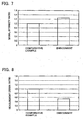
- Fig. 7 is a graph showing measured results of the signal intensity
- Fig. 8 is a graph showing results of measurement errors of the size.
- the signal intensity is described first.
- the graph of Fig. 7 shows the signal intensity in the embodiment represented by a ratio to the signal intensity in the comparative example, which is determined to have a value of one.
- the embodiment is provided with the tracks 41, 43 including flux coupling windings 51, 53 each in the shape of a ring (in the form of a gear) continuous as shown in Fig. 2. Accordingly, signals can be efficiently transmitted from the transmitting winding group G2 to the track group G3. Therefore, the intensity of the received signal can be enhanced. Thus, it is possible to obtain received signals with sufficient intensities from the receiving windings even if the encoder is downsized.
- Fig. 8 shows the measurement error in the embodiment by a ratio to the measurement error in the comparative example, which is determined to have a value of one. In the embodiment it is possible to achieve an improvement of about 50 % in measurement accuracy compared to the comparative example.
- a track includes a plurality of flux coupling windings 73 separated from each other, in which induced currents with different intensities flow, respectively.
- an induced current ia flowing in a flux coupling winding 73a differs in intensity from an induced current ib flowing in a flux coupling winding 73b. Therefore, the induced currents have different intensities in accordance with positions of the track, which may cause a reduction in measurement accuracy. For example, even the same displacement of 0.1 mm exerts a larger influence if the encoder is downsized.
- the flux coupling winding 51, 53 in one track is in the shape of a continuous ring as shown in Fig. 11. Accordingly, the induced current flowing in the track does not differ in accordance with positions of the track and can be made uniform. Therefore, in the embodiment it is possible to reduce the measurement error due to the displacement of the stator or the rotor.
- the encoder even if the encoder is downsized, it is possible to prevent the intensity of the received signal from lowering and reduce the influence from the displacement of the stator or the rotor. Accordingly, it is possible to realize a downsized absolute rotary encoder capable of achieving accurate measurements.
- one receiving winding 17, 19 is provided corresponding to each track (in the case of one-phase receiving winding) as shown in Fig. 1.
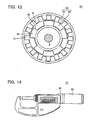
- three receiving windings may be provided corresponding to each track (in the case of three-phase receiving windings) as shown in Fig. 12.
- three receiving windings 17a, 17b, 17c arranged with different phases shifted from each other correspond to one track
- three receiving windings 19a, 19b, 19c arranged with different phases shifted from each other correspond to the other track.
- two or four receiving windings may be provided corresponding to each track (in the case of two- or four-phase receiving windings).
- the rotor 3 is not limited to the configuration shown in Fig. 2 but may have a configuration shown in Fig. 13.
- a rotor 81 includes an outer track 41 having sixteen blocks 61 and an inner track 43 having five blocks 61.
- Two tracks are contained in the track group G3 in the described example though three or more tracks may be contained.
- at least two tracks in the track group G3 may have blocks 61 (that is, the linear arc portions), which are different in number from each other.
- Fig. 14 is a front view of a micrometer 91 equipped with the absolute rotary encoder according to the embodiment.
- the stator 1 of Fig. 1 is fixed to a frame 93, and the rotor 93 of Fig. 2 is fixed to a thimble 95.
- the micrometer 91 is downsized such that the rotor 3 has a diameter of 20 mm or below, for example.
Abstract
Description
- The present invention relates to an absolute rotary encoder operative to measure displacements through the use of flux coupling, and amicrometer including the encoder mounted thereon.
- A rotary encoder comprises a stator having transmitting windings and receiving windings arranged thereon, and a rotor having tracks arranged thereon as capable of flux coupling with these windings. Such the encoder includes the absolute type as disclosed in
JP-A 10-213407 US Patent 3,812,481 (column 5, line 68 to column 6,line 3; column 7, lines 31-35; Figs. 1 and 2). In particular, the latter discloses a relatively large rotary encoder, which is applicable to control of internal combustion engines. Installation of the stator and the rotor into an enclosure may cause a displacement of the stator or the rotor. In this case, regardless of the size of the absolute rotary encoder, the extent of magnitude of the displacement is almost same. Therefore, downsizing the absolute rotary encoder results in an increase in influence from the displacement and causes a reduction in measurement accuracy. - The present invention has an object to provide an absolute rotary encoder capable of achieving accurate measurements even if it is downsized, and a micrometer including the encoder mounted thereon.
- The present invention provides an absolute rotary encoder, comprising: a shaft; a stator; a rotor having a bore passing through the center thereof to receive the shaft therein and arranged rotatably about the shaft and opposite the stator; a track group including tracks arranged concentrically on the rotor; a transmitting winding group arranged on the stator as capable of flux coupling with the track group; and a receiving winding group arranged on the stator as capable of flux coupling with the track group, wherein each track in the track group comprises a flux coupling winding that includes linear arc portions having first and second radii and arranged alternately on the rotor and has the shape of a ring continuous about the shaft, wherein the track group includes at least two tracks having the linear arc portions different in number from each other.
- In the absolute rotary encoder according to the present invention, each track comprises a flux coupling winding that includes linear arc portions having first and second radii and arranged alternately on the rotor and has the shape of a ring continuous about the shaft. Therefore, even if the absolute rotary encoder is downsized, it is possible to prevent the intensity of the received signal from lowering and reduce the influence from the displacement of the stator or the rotor.
- In the present invention, the transmitting winding group may be located more outward than the innermost receiving winding among a plurality of receiving windings contained in the receiving winding group. In this case, a transmitting winding is omitted, which is otherwise located more inward than the most inwardly located receiving winding. Accordingly, the absolute rotary encoder can be downsized.
- In the present invention, the transmitting winding group may comprise transmitting windings linked in a shape as drawn with one stroke. In this case, a transmitting winding driver can be shared to drive every transmitting winding. Accordingly, the absolute rotary encoder can be downsized. The absolute rotary encoder can be mounted on a micrometer.
- In accordance with the present invention, it is possible even for a downsized absolute rotary encoder to prevent the intensity of the signal received at the receiving windings from lowering and reduce the influence from the displacement of the stator or the rotor. Therefore, an accurate, downsized absolute rotary encoder can be realized.
-
- Fig. 1 is a plan view of a stator, which is a component of an absolute rotary encoder according to the embodiment;
- Fig. 2 is a plan view of a rotor, which is a component of the absolute rotary encoder according to the embodiment;
- Fig. 3 is a plan view of an example of a receiving winding arranged on the stator shown in Fig. 1;
- Fig. 4 is a plan view of another example of a receiving winding arranged on the stator shown in Fig. 1;
- Fig. 5 is a plan view of a receiving folded portion and vicinity of the receiving winding shown in Fig. 3;
- Fig. 6 is a plan view of a rotor, which is a component of an absolute rotary encoder according to a comparative example;
- Fig. 7 is a graph showing measured results of the signal intensity;
- Fig. 8 is a graph showing results of measurement errors of the size;
- Fig. 9 shows a displacement of the rotor relative to the stator;
- Fig. 10 shows current flowing in tracks when the rotor in the comparative example is displaced;
- Fig. 11 shows current flowing in tracks when the rotor in the embodiment is displaced;
- Fig. 12 is a plan view of three-phase receiving windings applicable to the embodiment;
- Fig. 13 is a plan view of another example of the rotor applicable to the embodiment; and
- Fig. 14 is a front view of a micrometer equipped with the absolute rotary encoder according to the embodiment.
- An absolute rotary encoder according to the embodiment will now be described with reference to the drawings (hereinafter the "absolute rotary encoder" may also be referred to as the "encoder"). In the figures, the same parts as those denoted with the reference numerals in the figure once described are given the same reference numerals and omitted from the following description.
- Fig. 1 is a plan view of a
stator 1, which is a component of the absolute rotary encoder according to the embodiment, and Fig. 2 is a plan view of arotor 3. Thestator 1 has abore 5 formed through the center, and a shaft 9 passes through thebore 5. Therotor 3 also has abore 11 through the center to receive the shaft 9 therein. Therotor 3 is arranged about the shaft 9 rotatably in the direction of the arrow A, interposing a rotor bush, not shown, fitted in thebore 11 therebetween, and opposite thestator 1. Thestator 1 and therotor 3 are composed of a printed circuit board, a glass substrate, a silicon substrate and so forth. - The
stator 1 shown in Fig. 1 comprises aninsulating substrate 15, on which receivingwindings receiving windings - Fig. 3 is a plan view of the receiving winding 17.. The receiving winding 17 includes a set U of an
upper conductor 21 and alower conductor 23 that intersects the upper conductor three-dimensionally, and plural such sets are arranged in a ring. An insulator layer, not shown, is located between theupper conductor 21 and thelower conductor 23. This insulator layer has a through-hole or via-hole formed therethrough to receive a buriedconductor 25 therein, through which an end of theupper conductor 21 is connected to an end of thelower conductor 23. In other words, the receiving winding 17 includes a plurality of approximatelydiamond receiving loops 27, which are arranged in a ring. - The
receiving loop 27 may be formed in various closed-loop shapes such as the shape of an almost sinusoidal wave. Fig. 4 is a plan view of a receiving winding composed of receivingloops 27 in the shape of an almost sinusoidal wave. This may be employed as thereceiving windings stator 1 shown in Fig. 1. - Fig. 5 is a plan view in the vicinity of a receiving folded
portion 29 of the receiving winding 17. The receiving foldedportion 29 is formed at two positions: both thefront 31 and the rear 33 of the receiving winding 17. In more detail, in thefront 31 thelower conductor 23 is folded at the receiving foldedportion 29, and in therear 33 theupper conductor 21 is folded at the receiving foldedportion 29. The receiving foldedportion 29 in thefront 31 is thelower conductor 23 and the receiving foldedportion 29 in the rear 33 is theupper conductor 21. Therefore, The receiving foldedportion 29 in thefront 31 is not connected to the receiving foldedportion 29 in the rear 33. - The receiving winding 19 of Fig. 1 has the same configuration as that of the receiving winding 17 except that an angle of rotation corresponding to the wavelength λ 2 of the
receiving winding 19 is different from that corresponding to the wavelength λ 1 of the receiving winding 17. - The
stator 1 includes transmittingwindings windings substrate 15. The transmitting winding 35 and the transmitting winding 37 are linked in a shape as drawn with one stroke to configure a transmitting winding group G2. As a result, a transmitting winding driver can be shared to drive the transmittingwindings - The transmitting winding group G2 is located more outward than the receiving winding 19, that is, more outward than the innermost receiving winding among the receiving
windings - Fig. 2 is referenced next to describe a configuration of the
rotor 3. Therotor 3 includes an insulatingsubstrate 39 in the shape of a disc.Tracks substrate 39 concentrically. Thetrack 41 is located outward and made capable of flux coupling with the receiving winding 17 and the transmitting winding group G2. To the contrary, thetrack 43 is located inward and made capable of flux coupling with the receiving winding 19 and the transmitting winding group G2. Thetracks - A configuration of the track group G3 is described taking the
track 41 as an example.Linear arc portions 45 with a radius r1 (an example of the first radius) andlinear arc portions 47 with a smaller radius r2 (an example of the second radius) are arranged alternately by tens. Thelinear arc portions linear portions 49 extending in the radial direction of therotor 3 to configure a flux coupling winding 51 in the shape of a ring continuous about the shaft 9. This flux coupling winding 51 serves as thetrack 41. The flux coupling winding 51 has a wavelength λ1, which is equal to the wavelength λ1 of the receiving winding 17. - The flux coupling winding 53 serving as the
track 43 compriseslinear arc portions 55 with a radius r3 (an example of the first radius) smaller than the radius r2, andlinear arc portions 57 with a much smaller radius r4 (an example of the second radius), which are arranged alternately by nines. Thelinear arc portions linear portions 59. The flux coupling winding 53 has a wavelength λ2, which is equal to the wavelength λ2 of the receiving winding 19. Thus, theflux coupling windings - A
linear arc portion 45 andlinear portions 49 at both sides thereof configure ablock 61, and alinear arc portion 55 andlinear portions 59 at both sides thereof configure ablock 61. The number ofblocks 61 is equal to ten in theouter track 41 and nine in theinner track 43. - In the encoder according to the embodiment comprising the
stator 1 of Fig. 1 and therotor 3 of Fig. 2, theouter track 41 is different from theinner track 43 in number ofblocks 61. Accordingly, on the basis of a difference between signals obtained from the receivingwindings rotor 3 within one rotation can be detected. - A major effect of the embodiment is described next in comparison with a comparative example. Fig. 6 is a plan view of a
rotor 71 according to the comparative example, which corresponds to Fig. 2. Therotor 71 differs from therotor 3 in configuration of tracks. In therotor 71 thetrack 41 includes tenflux coupling windings 73 arranged at a certain pitch while thetrack 43 includes nineflux coupling windings 73 arranged at a certain pitch. A flux coupling winding 73 is shaped in an almost rectangular frame. - The encoder equipped with the
rotor 3 according to the embodiment and the encoder equipped with therotor 71 according to the comparative example are employed to measure the size of a certain object to be measured under the following condition. Thetracks track 41. - During the above measurement, intensities of signals obtained from the receiving windings as well as measurement errors of the size are acquired. Fig. 7 is a graph showing measured results of the signal intensity, and Fig. 8 is a graph showing results of measurement errors of the size. The signal intensity is described first. The graph of Fig. 7 shows the signal intensity in the embodiment represented by a ratio to the signal intensity in the comparative example, which is determined to have a value of one.
- In the embodiment it is possible to achieve about 1.2 times the signal intensity of the comparative example. As described in the column of the subject to be solved by the invention, if the absolute rotary encoder is downsized, the current induced in tracks by flux coupling with the transmitting winding is made smaller, and received signals with sufficient intensities can not be obtained from the receiving windings.
- The embodiment is provided with the
tracks flux coupling windings - The following description is given to the measurement errors of the size. Fig. 8 shows the measurement error in the embodiment by a ratio to the measurement error in the comparative example, which is determined to have a value of one. In the embodiment it is possible to achieve an improvement of about 50 % in measurement accuracy compared to the comparative example.
- In the embodiment it is possible to reduce the measurement error due to the displacement of the rotor or the stator. The reason may be considered as follows. When the attached place of the rotor is displaced from the stator as shown in Fig. 9, the distance between the stator and the rotor becomes different in accordance with the position of the track. In this case, current flows in the tracks as considered below.
- As shown in Fig. 10, in the
rotor 71 of the comparative example, a track includes a plurality offlux coupling windings 73 separated from each other, in which induced currents with different intensities flow, respectively. For example, an induced current ia flowing in a flux coupling winding 73a differs in intensity from an induced current ib flowing in a flux coupling winding 73b. Therefore, the induced currents have different intensities in accordance with positions of the track, which may cause a reduction in measurement accuracy. For example, even the same displacement of 0.1 mm exerts a larger influence if the encoder is downsized. - To the contrary, in the
rotor 3 of the embodiment, the flux coupling winding 51, 53 in one track is in the shape of a continuous ring as shown in Fig. 11. Accordingly, the induced current flowing in the track does not differ in accordance with positions of the track and can be made uniform. Therefore, in the embodiment it is possible to reduce the measurement error due to the displacement of the stator or the rotor. - As described above, in the embodiment, even if the encoder is downsized, it is possible to prevent the intensity of the received signal from lowering and reduce the influence from the displacement of the stator or the rotor. Accordingly, it is possible to realize a downsized absolute rotary encoder capable of achieving accurate measurements.
- In the example described above, one receiving winding 17, 19 is provided corresponding to each track (in the case of one-phase receiving winding) as shown in Fig. 1. To the contrary, three receiving windings may be provided corresponding to each track (in the case of three-phase receiving windings) as shown in Fig. 12. In the latter, three receiving
windings windings - The
rotor 3 is not limited to the configuration shown in Fig. 2 but may have a configuration shown in Fig. 13. In this case, arotor 81 includes anouter track 41 having sixteenblocks 61 and aninner track 43 having fiveblocks 61. - Two tracks are contained in the track group G3 in the described example though three or more tracks may be contained. In this case, at least two tracks in the track group G3 may have blocks 61 (that is, the linear arc portions), which are different in number from each other.
- Fig. 14 is a front view of a
micrometer 91 equipped with the absolute rotary encoder according to the embodiment. Thestator 1 of Fig. 1 is fixed to aframe 93, and therotor 93 of Fig. 2 is fixed to athimble 95. In the embodiment it is possible to achieve accurate measurements even if themicrometer 91 is downsized such that therotor 3 has a diameter of 20 mm or below, for example.
Claims (7)
- An absolute rotary encoder, comprising:a shaft;a stator;a rotor having a bore passing through the center thereof to receive the shaft therein and arranged rotatably about the shaft and opposite the stator;a track group including tracks arranged concentrically on the rotor;a transmitting winding group arranged on the stator as capable of flux coupling with the track group; anda receiving winding group arranged on the stator as capable of flux coupling with the track group,wherein each track in the track group comprises a flux coupling winding that includes linear arc portions having first and second radii and arranged alternately on the rotor and has the shape of a ring continuous about the shaft,
wherein the track group includes at least two tracks having the linear arc portions different in number from each other. - The absolute rotary encoder according to claim 1, wherein the transmitting winding group is located more outward than the innermost receiving winding among a plurality of receiving windings contained in the receiving winding group.
- The absolute rotary encoder according to claim 1, wherein the transmitting winding group comprises transmitting windings linked in a shape as drawn with one stroke.
- The absolute rotary encoder according to claim 1, wherein each of the receiving windings contained in the receiving winding group includes a plurality of receiving loops in the form of closed-loops arranged in a ring.
- The absolute rotary encoder according to claim 1, wherein the receiving windings contained in the receiving winding group include an outer receiving winding and an inner receiving winding, said outer receiving winding having an angle of rotation corresponding its wavelength different from that corresponding to the wavelength of said inner receiving winding.
- The absolute rotary encoder according to claim 1. wherein the plurality of receiving windings are arranged with different phases corresponding to the respective tracks.
- A micrometer including the absolute rotary encoder according to claim 1 mounted thereon.
Applications Claiming Priority (1)
| Application Number | Priority Date | Filing Date | Title |
|---|---|---|---|
| JP2005120819 | 2005-04-19 |
Publications (3)
| Publication Number | Publication Date |
|---|---|
| EP1715298A2 true EP1715298A2 (en) | 2006-10-25 |
| EP1715298A3 EP1715298A3 (en) | 2014-03-12 |
| EP1715298B1 EP1715298B1 (en) | 2017-07-19 |
Family
ID=36954848
Family Applications (1)
| Application Number | Title | Priority Date | Filing Date |
|---|---|---|---|
| EP06008121.3A Active EP1715298B1 (en) | 2005-04-19 | 2006-04-19 | Absolute rotary encoder and micrometer |
Country Status (3)
| Country | Link |
|---|---|
| US (1) | US7385389B2 (en) |
| EP (1) | EP1715298B1 (en) |
| CN (1) | CN100420914C (en) |
Cited By (8)
| Publication number | Priority date | Publication date | Assignee | Title |
|---|---|---|---|---|
| CN102355553A (en) * | 2011-10-11 | 2012-02-15 | 陈博威 | Method for realizing light shadow calligraphic work |
| GB2490115A (en) * | 2011-04-18 | 2012-10-24 | Agilent Technologies Inc | Angular position encoder with grouped transmitters |
| EP2312272A3 (en) * | 2009-10-16 | 2014-01-15 | Mitutoyo Corporation | Rotary Encoder |
| US20150292910A1 (en) * | 2014-04-09 | 2015-10-15 | Mitutoyo Corporation | Induction detecting type rotary encoder |
| EP2757351A3 (en) * | 2013-01-18 | 2017-12-06 | Mitutoyo Corporation | Inductive detection type rotary encoder |
| EP3851805A1 (en) * | 2020-01-14 | 2021-07-21 | Mitutoyo Corporation | Rotary encoder |
| EP3901582A1 (en) * | 2020-04-23 | 2021-10-27 | Dr. Johannes Heidenhain GmbH | Inductive angle measuring device |
| WO2021249776A1 (en) * | 2020-06-10 | 2021-12-16 | HELLA GmbH & Co. KGaA | Inductive position sensor |
Families Citing this family (24)
| Publication number | Priority date | Publication date | Assignee | Title |
|---|---|---|---|---|
| JP5583317B2 (en) * | 2007-02-23 | 2014-09-03 | Ntn株式会社 | Rotation detection device and bearing with rotation detection device |
| JP5112779B2 (en) * | 2007-08-03 | 2013-01-09 | 株式会社ミツトヨ | Absolute position measuring device |
| JP5081553B2 (en) * | 2007-09-27 | 2012-11-28 | Ntn株式会社 | Rotation detection device and bearing with rotation detection device |
| CN101855522B (en) * | 2007-10-22 | 2013-01-30 | 铁姆肯公司 | Absolute position magnetic encoder with binary and decimal output |
| DE102008032419A1 (en) * | 2008-07-10 | 2010-01-14 | Dr. Johannes Heidenhain Gmbh | Encoders and series of encoders |
| JP5133199B2 (en) * | 2008-10-28 | 2013-01-30 | 株式会社ミツトヨ | Inductive detection type rotary encoder |
| JP5221494B2 (en) * | 2008-12-24 | 2013-06-26 | Ntn株式会社 | Rotation detection device and bearing with rotation detection device |
| JP5239025B2 (en) | 2009-03-11 | 2013-07-17 | 株式会社ミツトヨ | Inductive detection type rotary encoder |
| US8723511B2 (en) | 2010-04-26 | 2014-05-13 | Nidec Avtron Automation Corporation | Absolute encoder |
| US9163926B2 (en) | 2012-01-25 | 2015-10-20 | Mitutoyo Corporation | Inductive detection type rotary encoder |
| DE102012223037A1 (en) * | 2012-12-13 | 2014-06-18 | Dr. Johannes Heidenhain Gmbh | Inductive position measuring device |
| KR20160004323A (en) * | 2013-05-03 | 2016-01-12 | 케이에스알 아이피 홀딩스 엘엘씨. | Micro inductive sensor |
| CN103528605B (en) * | 2013-10-15 | 2015-11-11 | 北京航空航天大学 | A kind of capacitive absolute rotary encoder |
| CN105651158B (en) * | 2014-09-03 | 2018-05-01 | 葛幸华 | A kind of cylinder separate type inductosyn |
| DE102015016300A1 (en) | 2014-12-26 | 2016-06-30 | Mitutoyo Corporation | Inductive detection type rotary encoder |
| JP6480809B2 (en) * | 2015-05-21 | 2019-03-13 | オークマ株式会社 | Multi revolution detector |
| DE102018102094A1 (en) * | 2018-01-31 | 2019-08-01 | Thyssenkrupp Ag | Inductive angle sensor for a motor vehicle steering |
| FR3094085B1 (en) * | 2019-03-22 | 2021-02-26 | Continental Automotive | Reduced width inductive position sensor |
| CN111193357B (en) * | 2020-01-14 | 2022-06-28 | 连云港杰瑞电子有限公司 | Induction type absolute angle sensor |
| CN112097804B (en) * | 2020-09-17 | 2021-12-10 | 连云港杰瑞电子有限公司 | Eddy current induction type absolute value rotary encoder |
| US11598654B2 (en) * | 2020-12-14 | 2023-03-07 | Microchip Technology Inc. | High resolution angular inductive sensor and associated method of use |
| WO2022203740A1 (en) | 2021-03-25 | 2022-09-29 | Microchip Technology Incorporated | Sense coil for inductive rotational-position sensing, and related devices, systems, and methods |
| US11662260B2 (en) * | 2021-09-03 | 2023-05-30 | Allegro Microsystems, Llc | Linear inductive torque sensor |
| US20240068843A1 (en) * | 2022-08-26 | 2024-02-29 | Semiconductor Components Industries, Llc | Inductive angular position sensor |
Citations (2)
| Publication number | Priority date | Publication date | Assignee | Title |
|---|---|---|---|---|
| US3812481A (en) | 1971-11-26 | 1974-05-21 | Bosch Gmbh Robert | Non-contacting electrical rotary position and rotation transducer |
| JPH10213407A (en) | 1996-11-29 | 1998-08-11 | Dr Johannes Heidenhain Gmbh | Scanning member for position measuring device |
Family Cites Families (6)
| Publication number | Priority date | Publication date | Assignee | Title |
|---|---|---|---|---|
| CN2035457U (en) * | 1988-09-12 | 1989-04-05 | 王忠合 | Assembly scale for induction synchronizer |
| EP0743508A2 (en) * | 1995-05-16 | 1996-11-20 | Mitutoyo Corporation | Induced current position transducer |
| CH690933A5 (en) * | 1996-01-24 | 2001-02-28 | Hans Ulrich Meyer | An inductive displacement sensor. |
| DE19738836A1 (en) * | 1997-09-05 | 1999-03-11 | Hella Kg Hueck & Co | Inductive angle sensor |
| GB9721891D0 (en) * | 1997-10-15 | 1997-12-17 | Scient Generics Ltd | Symmetrically connected spiral transducer |
| DE10320990A1 (en) * | 2003-05-09 | 2004-11-25 | Dr. Johannes Heidenhain Gmbh | Inductive rotation angle sensor and rotary encoder equipped with it |
-
2006
- 2006-04-19 CN CNB2006100794393A patent/CN100420914C/en active Active
- 2006-04-19 US US11/406,273 patent/US7385389B2/en active Active
- 2006-04-19 EP EP06008121.3A patent/EP1715298B1/en active Active
Patent Citations (2)
| Publication number | Priority date | Publication date | Assignee | Title |
|---|---|---|---|---|
| US3812481A (en) | 1971-11-26 | 1974-05-21 | Bosch Gmbh Robert | Non-contacting electrical rotary position and rotation transducer |
| JPH10213407A (en) | 1996-11-29 | 1998-08-11 | Dr Johannes Heidenhain Gmbh | Scanning member for position measuring device |
Cited By (11)
| Publication number | Priority date | Publication date | Assignee | Title |
|---|---|---|---|---|
| EP2312272A3 (en) * | 2009-10-16 | 2014-01-15 | Mitutoyo Corporation | Rotary Encoder |
| US9234771B2 (en) | 2009-10-16 | 2016-01-12 | Mitutoyo Corporation | Rotary encoder to detect a change of quantity and measure rotation angle |
| GB2490115A (en) * | 2011-04-18 | 2012-10-24 | Agilent Technologies Inc | Angular position encoder with grouped transmitters |
| GB2490115B (en) * | 2011-04-18 | 2015-09-16 | Agilent Technologies Inc | Encoding device for determining an angular position |
| CN102355553A (en) * | 2011-10-11 | 2012-02-15 | 陈博威 | Method for realizing light shadow calligraphic work |
| EP2757351A3 (en) * | 2013-01-18 | 2017-12-06 | Mitutoyo Corporation | Inductive detection type rotary encoder |
| US20150292910A1 (en) * | 2014-04-09 | 2015-10-15 | Mitutoyo Corporation | Induction detecting type rotary encoder |
| US9551595B2 (en) * | 2014-04-09 | 2017-01-24 | Mitutoyo Corporation | Induction detecting type rotary encoder |
| EP3851805A1 (en) * | 2020-01-14 | 2021-07-21 | Mitutoyo Corporation | Rotary encoder |
| EP3901582A1 (en) * | 2020-04-23 | 2021-10-27 | Dr. Johannes Heidenhain GmbH | Inductive angle measuring device |
| WO2021249776A1 (en) * | 2020-06-10 | 2021-12-16 | HELLA GmbH & Co. KGaA | Inductive position sensor |
Also Published As
| Publication number | Publication date |
|---|---|
| CN1873367A (en) | 2006-12-06 |
| US7385389B2 (en) | 2008-06-10 |
| US20060250128A1 (en) | 2006-11-09 |
| EP1715298B1 (en) | 2017-07-19 |
| EP1715298A3 (en) | 2014-03-12 |
| CN100420914C (en) | 2008-09-24 |
Similar Documents
| Publication | Publication Date | Title |
|---|---|---|
| EP1715298B1 (en) | Absolute rotary encoder and micrometer | |
| JP4869769B2 (en) | Absolute rotary encoder and micrometer | |
| EP1647809B1 (en) | Induction type displacement detector | |
| US10837848B2 (en) | Ultra-thin combined inductive torque and angle sensor for steering wheel position sensing | |
| JP5239025B2 (en) | Inductive detection type rotary encoder | |
| US20140015384A1 (en) | Absolute encoder device and motor | |
| EP2265902B1 (en) | Inductive rotational angle sensor and method for operating an inductive rotational angle sensor | |
| JP4504064B2 (en) | Electromagnetic induction type rotation sensor and shaft encoder provided with the electromagnetic induction type rotation sensor | |
| CN101144725A (en) | Inductive position sensor | |
| JP2019506613A (en) | Rotation angle sensor | |
| EP2267413A1 (en) | Magnetic sensor and magnetic encoder | |
| JPH11248486A (en) | Position of rotary shaft and speed pickup | |
| US6711970B2 (en) | Device for measuring torque with high accuracy | |
| CN113124910B (en) | Rotary encoder | |
| US20040262498A1 (en) | Photodetector for optical encoder | |
| JP2008215911A (en) | Linear encoder and actuator | |
| CN100353138C (en) | Inductive displacement detector and micrometer | |
| CN116026231A (en) | Induction type angle measuring device | |
| CN101403626B (en) | Photodiode array, photodiode detection system and optical encoder | |
| CN114608628A (en) | Scanning element and inductive position measuring device having the same | |
| JP2005265518A (en) | Inductive displacement detector and micrometer | |
| JP4340133B2 (en) | Inductive displacement detector and micrometer | |
| US20240077338A1 (en) | Inductive Sensor Arrangement for Detecting a Rotational Movement | |
| JP2008275439A (en) | Induction detecting type rotary encoder | |
| JPH05264291A (en) | Absolute encoder |
Legal Events
| Date | Code | Title | Description |
|---|---|---|---|
| PUAI | Public reference made under article 153(3) epc to a published international application that has entered the european phase |
Free format text: ORIGINAL CODE: 0009012 |
|
| AK | Designated contracting states |
Kind code of ref document: A2 Designated state(s): AT BE BG CH CY CZ DE DK EE ES FI FR GB GR HU IE IS IT LI LT LU LV MC NL PL PT RO SE SI SK TR |
|
| AX | Request for extension of the european patent |
Extension state: AL BA HR MK YU |
|
| PUAL | Search report despatched |
Free format text: ORIGINAL CODE: 0009013 |
|
| AK | Designated contracting states |
Kind code of ref document: A3 Designated state(s): AT BE BG CH CY CZ DE DK EE ES FI FR GB GR HU IE IS IT LI LT LU LV MC NL PL PT RO SE SI SK TR |
|
| AX | Request for extension of the european patent |
Extension state: AL BA HR MK YU |
|
| RIC1 | Information provided on ipc code assigned before grant |
Ipc: G01D 5/244 20060101ALI20140131BHEP Ipc: G01D 5/245 20060101ALI20140131BHEP Ipc: G01D 5/20 20060101AFI20140131BHEP |
|
| 17P | Request for examination filed |
Effective date: 20140827 |
|
| RBV | Designated contracting states (corrected) |
Designated state(s): AT BE BG CH CY CZ DE DK EE ES FI FR GB GR HU IE IS IT LI LT LU LV MC NL PL PT RO SE SI SK TR |
|
| AKX | Designation fees paid |
Designated state(s): AT BE BG CH CY CZ DE DK EE ES FI FR GB GR HU IE IS IT LI LT LU LV MC NL PL PT RO SE SI SK TR |
|
| GRAP | Despatch of communication of intention to grant a patent |
Free format text: ORIGINAL CODE: EPIDOSNIGR1 |
|
| RIC1 | Information provided on ipc code assigned before grant |
Ipc: G01D 5/245 20060101ALI20170123BHEP Ipc: G01D 5/244 20060101ALI20170123BHEP Ipc: G01D 5/20 20060101AFI20170123BHEP |
|
| INTG | Intention to grant announced |
Effective date: 20170215 |
|
| GRAS | Grant fee paid |
Free format text: ORIGINAL CODE: EPIDOSNIGR3 |
|
| GRAA | (expected) grant |
Free format text: ORIGINAL CODE: 0009210 |
|
| AK | Designated contracting states |
Kind code of ref document: B1 Designated state(s): AT BE BG CH CY CZ DE DK EE ES FI FR GB GR HU IE IS IT LI LT LU LV MC NL PL PT RO SE SI SK TR |
|
| REG | Reference to a national code |
Ref country code: GB Ref legal event code: FG4D |
|
| REG | Reference to a national code |
Ref country code: CH Ref legal event code: EP |
|
| REG | Reference to a national code |
Ref country code: IE Ref legal event code: FG4D |
|
| REG | Reference to a national code |
Ref country code: AT Ref legal event code: REF Ref document number: 910828 Country of ref document: AT Kind code of ref document: T Effective date: 20170815 |
|
| REG | Reference to a national code |
Ref country code: DE Ref legal event code: R096 Ref document number: 602006053042 Country of ref document: DE |
|
| REG | Reference to a national code |
Ref country code: NL Ref legal event code: MP Effective date: 20170719 |
|
| REG | Reference to a national code |
Ref country code: LT Ref legal event code: MG4D |
|
| REG | Reference to a national code |
Ref country code: AT Ref legal event code: MK05 Ref document number: 910828 Country of ref document: AT Kind code of ref document: T Effective date: 20170719 |
|
| PG25 | Lapsed in a contracting state [announced via postgrant information from national office to epo] |
Ref country code: FI Free format text: LAPSE BECAUSE OF FAILURE TO SUBMIT A TRANSLATION OF THE DESCRIPTION OR TO PAY THE FEE WITHIN THE PRESCRIBED TIME-LIMIT Effective date: 20170719 Ref country code: SE Free format text: LAPSE BECAUSE OF FAILURE TO SUBMIT A TRANSLATION OF THE DESCRIPTION OR TO PAY THE FEE WITHIN THE PRESCRIBED TIME-LIMIT Effective date: 20170719 Ref country code: NL Free format text: LAPSE BECAUSE OF FAILURE TO SUBMIT A TRANSLATION OF THE DESCRIPTION OR TO PAY THE FEE WITHIN THE PRESCRIBED TIME-LIMIT Effective date: 20170719 Ref country code: AT Free format text: LAPSE BECAUSE OF FAILURE TO SUBMIT A TRANSLATION OF THE DESCRIPTION OR TO PAY THE FEE WITHIN THE PRESCRIBED TIME-LIMIT Effective date: 20170719 Ref country code: LT Free format text: LAPSE BECAUSE OF FAILURE TO SUBMIT A TRANSLATION OF THE DESCRIPTION OR TO PAY THE FEE WITHIN THE PRESCRIBED TIME-LIMIT Effective date: 20170719 |
|
| PG25 | Lapsed in a contracting state [announced via postgrant information from national office to epo] |
Ref country code: PL Free format text: LAPSE BECAUSE OF FAILURE TO SUBMIT A TRANSLATION OF THE DESCRIPTION OR TO PAY THE FEE WITHIN THE PRESCRIBED TIME-LIMIT Effective date: 20170719 Ref country code: IS Free format text: LAPSE BECAUSE OF FAILURE TO SUBMIT A TRANSLATION OF THE DESCRIPTION OR TO PAY THE FEE WITHIN THE PRESCRIBED TIME-LIMIT Effective date: 20171119 Ref country code: BG Free format text: LAPSE BECAUSE OF FAILURE TO SUBMIT A TRANSLATION OF THE DESCRIPTION OR TO PAY THE FEE WITHIN THE PRESCRIBED TIME-LIMIT Effective date: 20171019 Ref country code: GR Free format text: LAPSE BECAUSE OF FAILURE TO SUBMIT A TRANSLATION OF THE DESCRIPTION OR TO PAY THE FEE WITHIN THE PRESCRIBED TIME-LIMIT Effective date: 20171020 Ref country code: LV Free format text: LAPSE BECAUSE OF FAILURE TO SUBMIT A TRANSLATION OF THE DESCRIPTION OR TO PAY THE FEE WITHIN THE PRESCRIBED TIME-LIMIT Effective date: 20170719 Ref country code: ES Free format text: LAPSE BECAUSE OF FAILURE TO SUBMIT A TRANSLATION OF THE DESCRIPTION OR TO PAY THE FEE WITHIN THE PRESCRIBED TIME-LIMIT Effective date: 20170719 |
|
| REG | Reference to a national code |
Ref country code: FR Ref legal event code: PLFP Year of fee payment: 13 Ref country code: DE Ref legal event code: R097 Ref document number: 602006053042 Country of ref document: DE |
|
| PG25 | Lapsed in a contracting state [announced via postgrant information from national office to epo] |
Ref country code: CZ Free format text: LAPSE BECAUSE OF FAILURE TO SUBMIT A TRANSLATION OF THE DESCRIPTION OR TO PAY THE FEE WITHIN THE PRESCRIBED TIME-LIMIT Effective date: 20170719 Ref country code: RO Free format text: LAPSE BECAUSE OF FAILURE TO SUBMIT A TRANSLATION OF THE DESCRIPTION OR TO PAY THE FEE WITHIN THE PRESCRIBED TIME-LIMIT Effective date: 20170719 Ref country code: DK Free format text: LAPSE BECAUSE OF FAILURE TO SUBMIT A TRANSLATION OF THE DESCRIPTION OR TO PAY THE FEE WITHIN THE PRESCRIBED TIME-LIMIT Effective date: 20170719 |
|
| PLBE | No opposition filed within time limit |
Free format text: ORIGINAL CODE: 0009261 |
|
| STAA | Information on the status of an ep patent application or granted ep patent |
Free format text: STATUS: NO OPPOSITION FILED WITHIN TIME LIMIT |
|
| PG25 | Lapsed in a contracting state [announced via postgrant information from national office to epo] |
Ref country code: SK Free format text: LAPSE BECAUSE OF FAILURE TO SUBMIT A TRANSLATION OF THE DESCRIPTION OR TO PAY THE FEE WITHIN THE PRESCRIBED TIME-LIMIT Effective date: 20170719 Ref country code: EE Free format text: LAPSE BECAUSE OF FAILURE TO SUBMIT A TRANSLATION OF THE DESCRIPTION OR TO PAY THE FEE WITHIN THE PRESCRIBED TIME-LIMIT Effective date: 20170719 |
|
| 26N | No opposition filed |
Effective date: 20180420 |
|
| PG25 | Lapsed in a contracting state [announced via postgrant information from national office to epo] |
Ref country code: SI Free format text: LAPSE BECAUSE OF FAILURE TO SUBMIT A TRANSLATION OF THE DESCRIPTION OR TO PAY THE FEE WITHIN THE PRESCRIBED TIME-LIMIT Effective date: 20170719 |
|
| PG25 | Lapsed in a contracting state [announced via postgrant information from national office to epo] |
Ref country code: MC Free format text: LAPSE BECAUSE OF FAILURE TO SUBMIT A TRANSLATION OF THE DESCRIPTION OR TO PAY THE FEE WITHIN THE PRESCRIBED TIME-LIMIT Effective date: 20170719 |
|
| REG | Reference to a national code |
Ref country code: CH Ref legal event code: PL |
|
| REG | Reference to a national code |
Ref country code: BE Ref legal event code: MM Effective date: 20180430 |
|
| REG | Reference to a national code |
Ref country code: IE Ref legal event code: MM4A |
|
| PG25 | Lapsed in a contracting state [announced via postgrant information from national office to epo] |
Ref country code: LU Free format text: LAPSE BECAUSE OF NON-PAYMENT OF DUE FEES Effective date: 20180419 |
|
| PG25 | Lapsed in a contracting state [announced via postgrant information from national office to epo] |
Ref country code: BE Free format text: LAPSE BECAUSE OF NON-PAYMENT OF DUE FEES Effective date: 20180430 Ref country code: CH Free format text: LAPSE BECAUSE OF NON-PAYMENT OF DUE FEES Effective date: 20180430 Ref country code: LI Free format text: LAPSE BECAUSE OF NON-PAYMENT OF DUE FEES Effective date: 20180430 |
|
| PG25 | Lapsed in a contracting state [announced via postgrant information from national office to epo] |
Ref country code: IE Free format text: LAPSE BECAUSE OF NON-PAYMENT OF DUE FEES Effective date: 20180419 |
|
| PG25 | Lapsed in a contracting state [announced via postgrant information from national office to epo] |
Ref country code: TR Free format text: LAPSE BECAUSE OF FAILURE TO SUBMIT A TRANSLATION OF THE DESCRIPTION OR TO PAY THE FEE WITHIN THE PRESCRIBED TIME-LIMIT Effective date: 20170719 |
|
| PG25 | Lapsed in a contracting state [announced via postgrant information from national office to epo] |
Ref country code: HU Free format text: LAPSE BECAUSE OF FAILURE TO SUBMIT A TRANSLATION OF THE DESCRIPTION OR TO PAY THE FEE WITHIN THE PRESCRIBED TIME-LIMIT; INVALID AB INITIO Effective date: 20060419 Ref country code: PT Free format text: LAPSE BECAUSE OF FAILURE TO SUBMIT A TRANSLATION OF THE DESCRIPTION OR TO PAY THE FEE WITHIN THE PRESCRIBED TIME-LIMIT Effective date: 20170719 |
|
| PG25 | Lapsed in a contracting state [announced via postgrant information from national office to epo] |
Ref country code: CY Free format text: LAPSE BECAUSE OF FAILURE TO SUBMIT A TRANSLATION OF THE DESCRIPTION OR TO PAY THE FEE WITHIN THE PRESCRIBED TIME-LIMIT Effective date: 20170719 |
|
| PGFP | Annual fee paid to national office [announced via postgrant information from national office to epo] |
Ref country code: IT Payment date: 20230426 Year of fee payment: 18 Ref country code: FR Payment date: 20230420 Year of fee payment: 18 Ref country code: DE Payment date: 20230420 Year of fee payment: 18 |
|
| PGFP | Annual fee paid to national office [announced via postgrant information from national office to epo] |
Ref country code: GB Payment date: 20230419 Year of fee payment: 18 |