EP1715279A1 - Heat exchanger, method for manufacturing same, and artificial heart-lung machine - Google Patents
Heat exchanger, method for manufacturing same, and artificial heart-lung machine Download PDFInfo
- Publication number
- EP1715279A1 EP1715279A1 EP05709809A EP05709809A EP1715279A1 EP 1715279 A1 EP1715279 A1 EP 1715279A1 EP 05709809 A EP05709809 A EP 05709809A EP 05709809 A EP05709809 A EP 05709809A EP 1715279 A1 EP1715279 A1 EP 1715279A1
- Authority
- EP
- European Patent Office
- Prior art keywords
- tubes
- housing
- heat exchanger
- fixing members
- fluid
- Prior art date
- Legal status (The legal status is an assumption and is not a legal conclusion. Google has not performed a legal analysis and makes no representation as to the accuracy of the status listed.)
- Granted
Links
- 238000004519 manufacturing process Methods 0.000 title claims description 36
- 238000000034 method Methods 0.000 title claims description 16
- 238000007789 sealing Methods 0.000 claims abstract description 125
- 239000012530 fluid Substances 0.000 claims abstract description 69
- 238000007599 discharging Methods 0.000 claims abstract description 10
- 229920005989 resin Polymers 0.000 claims description 57
- 239000011347 resin Substances 0.000 claims description 57
- 239000000463 material Substances 0.000 claims description 52
- 239000008280 blood Substances 0.000 claims description 30
- 210000004369 blood Anatomy 0.000 claims description 30
- 229920005749 polyurethane resin Polymers 0.000 claims description 8
- 238000001746 injection moulding Methods 0.000 claims description 7
- 229920005668 polycarbonate resin Polymers 0.000 claims description 6
- 239000004431 polycarbonate resin Substances 0.000 claims description 6
- 239000003822 epoxy resin Substances 0.000 claims description 5
- 229920000647 polyepoxide Polymers 0.000 claims description 5
- BZHJMEDXRYGGRV-UHFFFAOYSA-N Vinyl chloride Chemical compound ClC=C BZHJMEDXRYGGRV-UHFFFAOYSA-N 0.000 claims description 4
- 238000005304 joining Methods 0.000 claims description 3
- 230000010354 integration Effects 0.000 claims description 2
- XLYOFNOQVPJJNP-UHFFFAOYSA-N water Substances O XLYOFNOQVPJJNP-UHFFFAOYSA-N 0.000 description 27
- 238000002347 injection Methods 0.000 description 21
- 239000007924 injection Substances 0.000 description 21
- 210000004072 lung Anatomy 0.000 description 9
- 230000017531 blood circulation Effects 0.000 description 8
- 239000007789 gas Substances 0.000 description 8
- 239000012510 hollow fiber Substances 0.000 description 8
- CURLTUGMZLYLDI-UHFFFAOYSA-N Carbon dioxide Chemical compound O=C=O CURLTUGMZLYLDI-UHFFFAOYSA-N 0.000 description 6
- 230000000717 retained effect Effects 0.000 description 5
- 238000011109 contamination Methods 0.000 description 4
- MYMOFIZGZYHOMD-UHFFFAOYSA-N Dioxygen Chemical compound O=O MYMOFIZGZYHOMD-UHFFFAOYSA-N 0.000 description 3
- 239000000853 adhesive Substances 0.000 description 3
- 230000001070 adhesive effect Effects 0.000 description 3
- 230000015572 biosynthetic process Effects 0.000 description 3
- 229910002092 carbon dioxide Inorganic materials 0.000 description 3
- 239000001569 carbon dioxide Substances 0.000 description 3
- 230000007423 decrease Effects 0.000 description 3
- 229910001882 dioxygen Inorganic materials 0.000 description 3
- 239000011295 pitch Substances 0.000 description 3
- -1 polypropylene Polymers 0.000 description 3
- 230000008569 process Effects 0.000 description 3
- 208000010496 Heart Arrest Diseases 0.000 description 2
- 230000008901 benefit Effects 0.000 description 2
- 239000007769 metal material Substances 0.000 description 2
- 238000000465 moulding Methods 0.000 description 2
- 238000004382 potting Methods 0.000 description 2
- 230000009467 reduction Effects 0.000 description 2
- 238000001356 surgical procedure Methods 0.000 description 2
- 239000004593 Epoxy Substances 0.000 description 1
- JOYRKODLDBILNP-UHFFFAOYSA-N Ethyl urethane Chemical compound CCOC(N)=O JOYRKODLDBILNP-UHFFFAOYSA-N 0.000 description 1
- 239000004743 Polypropylene Substances 0.000 description 1
- XUIMIQQOPSSXEZ-UHFFFAOYSA-N Silicon Chemical compound [Si] XUIMIQQOPSSXEZ-UHFFFAOYSA-N 0.000 description 1
- 208000007536 Thrombosis Diseases 0.000 description 1
- QVGXLLKOCUKJST-UHFFFAOYSA-N atomic oxygen Chemical compound [O] QVGXLLKOCUKJST-UHFFFAOYSA-N 0.000 description 1
- 230000004087 circulation Effects 0.000 description 1
- 230000003247 decreasing effect Effects 0.000 description 1
- 238000001514 detection method Methods 0.000 description 1
- 230000000694 effects Effects 0.000 description 1
- LNEPOXFFQSENCJ-UHFFFAOYSA-N haloperidol Chemical compound C1CC(O)(C=2C=CC(Cl)=CC=2)CCN1CCCC(=O)C1=CC=C(F)C=C1 LNEPOXFFQSENCJ-UHFFFAOYSA-N 0.000 description 1
- 238000009434 installation Methods 0.000 description 1
- 239000011159 matrix material Substances 0.000 description 1
- 230000007246 mechanism Effects 0.000 description 1
- 238000012544 monitoring process Methods 0.000 description 1
- 229910052760 oxygen Inorganic materials 0.000 description 1
- 239000001301 oxygen Substances 0.000 description 1
- 230000036284 oxygen consumption Effects 0.000 description 1
- 238000012856 packing Methods 0.000 description 1
- 229920006122 polyamide resin Polymers 0.000 description 1
- 229920001155 polypropylene Polymers 0.000 description 1
- 239000004800 polyvinyl chloride Substances 0.000 description 1
- 229920000915 polyvinyl chloride Polymers 0.000 description 1
- 230000029058 respiratory gaseous exchange Effects 0.000 description 1
- 229910052710 silicon Inorganic materials 0.000 description 1
- 239000010703 silicon Substances 0.000 description 1
- 229920001187 thermosetting polymer Polymers 0.000 description 1
Images






Classifications
-
- F—MECHANICAL ENGINEERING; LIGHTING; HEATING; WEAPONS; BLASTING
- F28—HEAT EXCHANGE IN GENERAL
- F28F—DETAILS OF HEAT-EXCHANGE AND HEAT-TRANSFER APPARATUS, OF GENERAL APPLICATION
- F28F9/00—Casings; Header boxes; Auxiliary supports for elements; Auxiliary members within casings
- F28F9/02—Header boxes; End plates
- F28F9/0229—Double end plates; Single end plates with hollow spaces
-
- A—HUMAN NECESSITIES
- A61—MEDICAL OR VETERINARY SCIENCE; HYGIENE
- A61M—DEVICES FOR INTRODUCING MEDIA INTO, OR ONTO, THE BODY; DEVICES FOR TRANSDUCING BODY MEDIA OR FOR TAKING MEDIA FROM THE BODY; DEVICES FOR PRODUCING OR ENDING SLEEP OR STUPOR
- A61M1/00—Suction or pumping devices for medical purposes; Devices for carrying-off, for treatment of, or for carrying-over, body-liquids; Drainage systems
- A61M1/14—Dialysis systems; Artificial kidneys; Blood oxygenators ; Reciprocating systems for treatment of body fluids, e.g. single needle systems for hemofiltration or pheresis
- A61M1/16—Dialysis systems; Artificial kidneys; Blood oxygenators ; Reciprocating systems for treatment of body fluids, e.g. single needle systems for hemofiltration or pheresis with membranes
- A61M1/1698—Blood oxygenators with or without heat-exchangers
-
- A—HUMAN NECESSITIES
- A61—MEDICAL OR VETERINARY SCIENCE; HYGIENE
- A61M—DEVICES FOR INTRODUCING MEDIA INTO, OR ONTO, THE BODY; DEVICES FOR TRANSDUCING BODY MEDIA OR FOR TAKING MEDIA FROM THE BODY; DEVICES FOR PRODUCING OR ENDING SLEEP OR STUPOR
- A61M1/00—Suction or pumping devices for medical purposes; Devices for carrying-off, for treatment of, or for carrying-over, body-liquids; Drainage systems
- A61M1/36—Other treatment of blood in a by-pass of the natural circulatory system, e.g. temperature adaptation, irradiation ; Extra-corporeal blood circuits
- A61M1/3621—Extra-corporeal blood circuits
- A61M1/3623—Means for actively controlling temperature of blood
-
- A—HUMAN NECESSITIES
- A61—MEDICAL OR VETERINARY SCIENCE; HYGIENE
- A61M—DEVICES FOR INTRODUCING MEDIA INTO, OR ONTO, THE BODY; DEVICES FOR TRANSDUCING BODY MEDIA OR FOR TAKING MEDIA FROM THE BODY; DEVICES FOR PRODUCING OR ENDING SLEEP OR STUPOR
- A61M1/00—Suction or pumping devices for medical purposes; Devices for carrying-off, for treatment of, or for carrying-over, body-liquids; Drainage systems
- A61M1/36—Other treatment of blood in a by-pass of the natural circulatory system, e.g. temperature adaptation, irradiation ; Extra-corporeal blood circuits
- A61M1/369—Temperature treatment
-
- F—MECHANICAL ENGINEERING; LIGHTING; HEATING; WEAPONS; BLASTING
- F28—HEAT EXCHANGE IN GENERAL
- F28D—HEAT-EXCHANGE APPARATUS, NOT PROVIDED FOR IN ANOTHER SUBCLASS, IN WHICH THE HEAT-EXCHANGE MEDIA DO NOT COME INTO DIRECT CONTACT
- F28D7/00—Heat-exchange apparatus having stationary tubular conduit assemblies for both heat-exchange media, the media being in contact with different sides of a conduit wall
- F28D7/16—Heat-exchange apparatus having stationary tubular conduit assemblies for both heat-exchange media, the media being in contact with different sides of a conduit wall the conduits being arranged in parallel spaced relation
- F28D7/163—Heat-exchange apparatus having stationary tubular conduit assemblies for both heat-exchange media, the media being in contact with different sides of a conduit wall the conduits being arranged in parallel spaced relation with conduit assemblies having a particular shape, e.g. square or annular; with assemblies of conduits having different geometrical features; with multiple groups of conduits connected in series or parallel and arranged inside common casing
- F28D7/1653—Heat-exchange apparatus having stationary tubular conduit assemblies for both heat-exchange media, the media being in contact with different sides of a conduit wall the conduits being arranged in parallel spaced relation with conduit assemblies having a particular shape, e.g. square or annular; with assemblies of conduits having different geometrical features; with multiple groups of conduits connected in series or parallel and arranged inside common casing the conduit assemblies having a square or rectangular shape
-
- A—HUMAN NECESSITIES
- A61—MEDICAL OR VETERINARY SCIENCE; HYGIENE
- A61M—DEVICES FOR INTRODUCING MEDIA INTO, OR ONTO, THE BODY; DEVICES FOR TRANSDUCING BODY MEDIA OR FOR TAKING MEDIA FROM THE BODY; DEVICES FOR PRODUCING OR ENDING SLEEP OR STUPOR
- A61M2205/00—General characteristics of the apparatus
- A61M2205/36—General characteristics of the apparatus related to heating or cooling
- A61M2205/366—General characteristics of the apparatus related to heating or cooling by liquid heat exchangers
-
- F—MECHANICAL ENGINEERING; LIGHTING; HEATING; WEAPONS; BLASTING
- F28—HEAT EXCHANGE IN GENERAL
- F28F—DETAILS OF HEAT-EXCHANGE AND HEAT-TRANSFER APPARATUS, OF GENERAL APPLICATION
- F28F2265/00—Safety or protection arrangements; Arrangements for preventing malfunction
- F28F2265/16—Safety or protection arrangements; Arrangements for preventing malfunction for preventing leakage
-
- Y—GENERAL TAGGING OF NEW TECHNOLOGICAL DEVELOPMENTS; GENERAL TAGGING OF CROSS-SECTIONAL TECHNOLOGIES SPANNING OVER SEVERAL SECTIONS OF THE IPC; TECHNICAL SUBJECTS COVERED BY FORMER USPC CROSS-REFERENCE ART COLLECTIONS [XRACs] AND DIGESTS
- Y10—TECHNICAL SUBJECTS COVERED BY FORMER USPC
- Y10T—TECHNICAL SUBJECTS COVERED BY FORMER US CLASSIFICATION
- Y10T29/00—Metal working
- Y10T29/49—Method of mechanical manufacture
- Y10T29/4935—Heat exchanger or boiler making
- Y10T29/49391—Tube making or reforming
Definitions
- the present invention relates to a heat exchanger, particularly to a heat exchanger used in medical equipment such as a heart-lung machine, a method for manufacturing the same, and a heart-lung machine in which the heat exchanger is used.
- a heart-lung machine In heart surgery that involves cardiac arrest in a patient, a heart-lung machine is used for taking over the functions of respiration and circulation during the cardiac arrest. Further, during the surgery, it is necessary to lower the patient's temperature and maintain the same so that the patient's oxygen consumption should decrease.
- the heart-lung machine is equipped with a heat exchanger to control the temperature of blood taken out of the patient.
- a bellows-type heat exchanger see Non-Patent Document 1, for instance
- a multi-tubular heat exchanger see Patent Document 1, for instance
- the multi-tubular heat exchanger has a larger area used for heat exchange as compared with the bellows-type heat exchanger with the same device capacity, and hence, it has the advantage of a higher heat exchange ratio as compared with the bellows-type heat exchanger. Accordingly, the use of the multi-tubular heat exchanger is considered to contribute to the downsizing of the heart-lung machine.
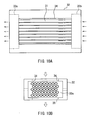
- FIGS. 10A and 10B show a conventional multi-tubular heat exchanger.
- FIG. 10A is a top view of the same, while FIG. 10B is a front view of the same.
- FIG. 11 is a perspective view illustrating tubes and sealing members composing the conventional multi-tubular heat exchanger shown in FIGS. 10A and 10B.
- the heat exchanger shown in FIGS. 10A and 10B is a heat exchanger for medical use.
- the conventional multi-tubular heat exchanger includes a plurality of tubes 31 through which blood taken out of a patient flows, a housing 32 for housing the tubes 31, and sealing members 33a and 33b.
- the sealing members 33a and 33b are disposed at ends of the tubes 31 on opposite sides, respectively, so as to seal cold/hot water (heat medium) flowing over surfaces of the tubes 31.
- the tubes 31 are fixed in the housing 32 by the sealing members 33a and 33b.
- the tubes 31 are arrayed regularly at uniform pitches as shown in FIGS. 10A, 10B, and 11 to improve the heat exchange ratio. It should be noted that arrows in FIG. 10Aindicate a direction of blood flow, and arrows in FIG. 10B indicate a direction of flow of cold/hot water.
- a space between the sealing members 33a and 33b in the housing 32 constitutes a flow path through which cold/hot water flows.
- the sealing members 33a and 33b are formed in a manner such that they are in close contact with internal faces of the housing 32 and external faces of the tubes 31, whereby the sealing of cold/hot water flowing the flow path is achieved:
- the housing 32 is provided with an inlet 34 and an outlet 35 for cold/hot water whose positions are matched to positions of mouths of the flow path for cold/hot water.
- the heat exchanger shown in FIGS. 10A, 10B, and 11 is formed with the following procedure. First, a plate (not shown) provided with a plurality of through holes is prepared, and tubes 31 are inserted into the through holes (not shown) of the plate, respectively. Then, the tubes 31 in this state are housed in a housing 32, and the first potting is performed. Further, in a state in which the plate is removed, the second potting is performed, whereby the sealing members 33a and 33b are completed. Thus, the multi-tubular heat exchanger as shown in FIGS. 10A, 10B, and 11 is obtained.
- Patent document 1 JP 11(1999)-47269 A (FIGS. 4 and 10)
- Non-patent document 1 " TRILIUM AFFINITY NT Oxygenator" Medtronic, 2000, U.S .
- the multi-tubular heat exchanger as shown in FIGS. 10A, 10B, and 11 has an advantage of a higher heat exchange ratio as compared with that of the bellows-type heat exchanger, whereas it has a problem of a higher production cost as compared with the cost of the bellows-type heat exchanger since the manufacture of the same requires many steps to achieve regular arrangement of the tubes 31 at uniform pitches as described above.
- Such a higher cost of the heat exchanger increases the cost of the heart-lung machine, thereby resulting in an increase in expenses for medical care, i.e., an increase in the burden on a patient.
- the cold/hot water normally has a pressure higher than that of blood. Therefore, when the sealing members 33a and 33b become leaky, in some cases the cold/hot water intrudes in the inside of the tubes 31, the artificial lung (not shown) connected to mouths of the tubes 31 on the blood outgoing side, etc., thereby contaminating blood.
- a heat exchanger manufacturing method is a method for manufacturing a heat exchanger that includes a plurality of tubes through which a first fluid passes and a housing in a tubular shape, wherein an inlet for introducing the second fluid into the housing and an outlet for discharging the second fluid are provided in sidewalls of the housing, and the method includes at least the steps of: (a) arranging the tubes in parallel with one another at intervals in a manner such that central axes of the tubes are positioned on the same plane; (b) forming a tube group by fixing and integrating the tubes in the arrayed state with use of band-like fixing members that are extended in a direction perpendicular to the central axes of the tubes so as to encircle all the tubes, the fixing members being at least two arranged at intervals along a direction of the central axes; (c) forming a heat exchange module by preparing a plurality of the tube groups and stacking the same, wherein
- a heart-lung machine according to the present invention is characterized by including the above-described heat exchanger according to the present invention.
- a heat exchanger includes at least a plurality of tubes through which a first fluid passes, a housing in which the tubes are installed, and sealing members for sealing a second fluid that flows over surfaces of the tubes, and is characterized as follows: the housing includes an inlet for introducing the second fluid into the housing, as well as a first outlet and a second outlet for discharging the second fluid out of the housing; the tubes are arranged in parallel with one another in the housing; the sealing members include at least a first sealing member positioned on one of end sides of the tubes, a second sealing member positioned on the other end side of the tubes, and a third sealing member positioned between the first and second sealing members; the third sealing member is provided so that a gap is provided between the first sealing member and the third sealing member while another gap is provided between the second sealing member and the third sealing member, and that a flow path is formed therein for guiding the second fluid introduced through the inlet toward the first outlet; and the second outlet is provided in the housing so as to be connected to the gaps
- the heat exchanger according to the present invention preferably is embodied so that the tubes are arranged so that in a cross-sectional plane perpendicular to a direction of central axes of the tubes, a figure bounded by lines meeting at cross-sectional centers of three neighboring tubes is an equilateral triangle.
- the second fluid passing through the flow path is blood
- the heat exchanger preferably is adapted to form a part of a heart-lung machine.
- a heat exchanger manufacturing method is a method for manufacturing a heat exchanger that includes a plurality of tubes through which a first fluid passes and a housing in a tubular shape, wherein an inlet for introducing the second fluid into the housing and an outlet for discharging the second fluid are provided in sidewalls of the housing, and the method includes at least the steps of: (a) arranging the tubes in parallel with one another at intervals in a manner such that central axes of the tubes are positioned on the same plane; (b) forming a tube group by fixing and integrating the tubes in the arrayed state with use of band-like fixing members that are extended in a direction perpendicular to the central axes of the tubes so as to encircle all the tubes, the fixing members being at least two arranged at intervals along a direction of the central axes; (c) forming a heat exchange module by preparing a plurality of the tube groups and stacking the same, wherein the fixing members of each tube group are brought into close contact, in
- the heat exchanger manufacturing method preferably is embodied so that: in the step (b), the fixing members of each tube group are four in number, which are arranged at intervals along the direction of the central axes, two of the four fixing members being inner fixing members and the other two being outer fixing members disposed relatively outward with respect to the two inner fixing members, and two inner fixing members are positioned so that the inlet and the outlet are positioned between the two inner fixing members; and in the step (e), the resin material is filled into a space between the two inner fixing members of each tube group in the housing in a manner such that a flow path for guiding the second fluid introduced through the inlet toward the outlet is formed in the space, and further, the resin material is filled in interstices around the tubes between one of the openings of the housing on one side and the outer fixing member of each tube group on the same side, as well as interstices around the tubes between the other opening of the housing on the other side and the outer fixing member of each tube group on the same side.
- the inlet and the outlet are formed, each in a round shape, at positions such that they are opposed to each other, and that in the step (e), the filling of the resin material into the space between the two inner fixing members of each tube group in the housing is carried out by rotating the housing around an axis extending from the center of the inlet to the center of the outlet.
- the steps (a) and (b) are carried out by using an upper die and a lower die, in each of which a plurality of first grooves where the tubes are to be disposed and a second groove orthogonally crossing the first grooves are formed; in the step (a), the arrangement of the tubes is carried out by disposing the tubes in the first grooves in either one of the upper and lower dies; and in the step (b), the integration with use of the fixing members is carried out by joining the upper and lower dies and injecting a resin material into the space formed by the second grooves in the upper and lower dies so that the fixing members are formed by injection molding.
- FIGS. 1A to 1C show a configuration of an example of the heat exchanger according to the present invention.
- FIG. 1A is a top view thereof
- FIG. 1B is a side view thereof
- FIG. 1C is a front view thereof.
- FIG. 2 is a partially cut-away perspective view showing the inside of a housing in the heat exchanger shown in FIGS. 1A to 1C.
- the heat exchanger includes a plurality of tubes 1 through which a first fluid flows, a housing 2 in which the tubes 1 are installed, and sealing members 3a to 3c for sealing a second fluid that flows over surfaces of the tubes 1.
- the tubes 1 are arrayed in parallel with one another in the housing 2.
- the tubes 1 are arranged three-dimensionally. More specifically, the tubes 1 are arranged in the following manner such that in a cross-sectional plane perpendicular to a direction of central axes of the tubes 1 (this direction is hereinafter referred to as "tube 1 central axis direction"), a figure bounded by lines meeting at cross-sectional centers of three neighboring tubes 1 is an equilateral triangle; in other words, in a manner such that the tubes 1 in a given row are not aligned vertically with the tubes 1 in another row immediately below the foregoing given row” respectively (see FIG. 1B).
- the arrangement of the tubes 1 is not limited to the example shown in FIGS. 1A to 1C and 2.
- the tubes 1 may be arranged so that in a cross section perpendicular to the tube 1 central axis direction, respective cross sections of the tubes 1 are arrayed in a matrix form; in other words, in a manner such that, the tubes 1 in a given row are aligned vertically with the tubes 1 another row immediately below the foregoing given row, respectively.
- the tubes 1 preferably are arranged in a manner such that the tubes 1 in a given row are not aligned vertically with the tubes 1 in the another row immediately below the foregoing given row, respectively, as shown in FIGS. 1A to 1C and 2.
- the housing 2 includes an inlet 4 for introducing a second fluid into the housing, and a first outlet 5 for discharging the second fluid from the housing.
- the inlet 4 also constitutes an inlet of a flow path 8 for the second fluid, which will be described later, while the first outlet 5 also constitutes an outlet of the flow path 8 of the second fluid, which will be described later.
- the housing 2 is formed in a tubular shape having a rectangular cross section, and the inlet 4 and the outlet 5 are disposed respectively on sidewalls of the housing that are opposed to each other.
- the inlet 4 and the first outlet 5 are matched to the mouths of the flow path 8.
- “the inlet 4 and the first outlet 5 are matched to the mouths of the flow path 8" does not exclusively indicate the case where the inlet 4 and the first outlet 5 are identical to the mouths of the flow path 8. This description is meant to signify that the inlet 4 and the first outlet 5 may be continuous with the mouths of the flow path 8.
- the sealing members include a first sealing member 3a positioned on one of end sides of the tubes 1, a second sealing member 3b positioned on the other end side of the tubes 1, and a third sealing member 3c positioned between the first and second sealing members 3a and 3b.
- the sealing of the tubes 1 from one another is achieved by these first, second, and third sealing members 3a, 3b, and 3c.
- the sealing members positioned at ends of the tubes 1 are provided separately. Further, the gaps 7 are formed between the first sealing member 3a and the flow path 8 for the second fluid and between the second sealing member 3b and the flow path 8 for the second fluid.
- the second fluid leaks due to leakage of the third sealing member 3c the second fluid having leaked is retained temporarily in the gaps 7, and thereafter is discharged through the second outlets 6 to outside the heat exchanger.
- the first fluid leaks due to leakage of the first sealing member 3a or the second sealing member 3b the first fluid having leaked is retained temporarily in the gap 7, and thereafter is discharged through the second outlets 6 to outside the heat exchanger.
- a safety mechanism is provided to prevent the first fluid flowing through the tubes 1 from intruding into the flow path 8 and to prevent the second fluid flowing through the flow path 8 from intruding into the tubes 1. Further, by monitoring the discharge of fluid through the second outlets 6, the detection of sealing leakage can be performed. Still further, by checking discharged fluid, it can be determined which sealing member has been leaking.
- FIGS. 1A to 1C a case where the heat exchanger shown in FIGS. 1A to 1C is used in a heart-lung machine is considered.
- the first, second, and third sealing members 3a, 3b, and 3c become leaky, the cold/hot water flows toward the flow path 8 since it has a higher pressure.
- the cold/hot water having leaked out of the first or second sealing member 3a or 3b is retained in the gap 7 temporarily, and is discharged through the second outlets 6 to outside the heat exchanger.
- the sealing leakage can be detected, and the occurrence of blood contamination as described in the "background art" section can be prevented.
- the cross-sectional shape of the flow path 8 and the shapes of the inlet 4 and the first outlet 5 preferably are round, as in the example shown in FIGS. 1A to 1C and 2. This is because by forming them in round shapes, the occurrence of thrombus can be suppressed at the flow path 8, the inlet 4, and the first outlet 5. It should be noted that in the present invention, the cross-sectional shape of the flow path 8 and the shapes of the inlet 4 and the first outlet 5 may be a rectangular shape, or another polygonal shape.
- the heat exchanger obtained by the following manufacturing method is identical to the heat exchanger shown in FIGS. 1A to 1C and 2, and includes a plurality of tubes 1 through which a first fluid passes, a tubular housing 2, and sealing members 3a to 3c.
- an inlet 4 for introducing a second fluid into the housing, and a first outlet 5 for discharging the second fluid therefrom are formed.
- the sealing members are composed of three sealing members 3a to 3c that are formed with gaps 7 being provided therebetween.
- second outlets 6 continuous with the gaps 7 are formed also.
- a plurality of tubes 1 are arranged in parallel at intervals so that central axes of the tubes 1 are positioned on the same plane. Further, the tubes 1 are fixed and integrated in the arrayed state described above with use of band-like fixing members 9a to 9d extended in a direction perpendicular to the tube 1 central axis direction so as to encircle all the tubes. As a result, the tube group 10 is obtained.
- the formation of the tube group 10 is performed by insert molding that utilizes an upper die and a lower die (not shown). More specifically, in each of the upper die and the lower die, a plurality of first grooves (not shown) and a plurality of second grooves (not shown) are formed.
- the first grooves in the upper die and the lower die are formed so that the tubes 1 can be disposed therein. Further, the first grooves in the upper die and the first grooves in the lower die are matched to each other when the upper and lower dies are joined. Therefore, by disposing the tubes 1 in the first grooves in either one of the upper and lower dies, the positioning of the tubes 1 is achieved.
- the second grooves are formed so as to cross the first grooves orthogonally Further, the second grooves in the upper die and the second grooves in the lower die are matched to each other when the upper and lower are joined, and form cavities that are used for forming the fixing members 9a to 9d.
- the arrangement of the tubes 1 is achieved by, in either one of the upper and lower dies, disposing the tubes 1 in the plurality of first grooves formed in the die, respectively.
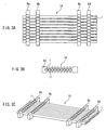
- the fixing members 9a to 9d are formed by injection molding. Through this injection molding, the tubes 1 are fixed with each other in an arranged state and integrated, as shown in FIGS. 3A to 3C.
- examples of the resin material used for forming the fixing members include resins for injection molding that exhibit excellent fluidity and small shrinkage after molding, such as polycarbonate resins, polyamide resins, polyurethane resins, polypropylene resins, and poly(vinyl chloride) resins.
- a polycarbonate resin or a vinyl chloride resin is used preferably. This is because, as will be described later (see FIGS. 4A to 4C), in the present example, the fixing members 9a to 9d of the tube groups 10 neighboring to each other in the vertical direction are placed in close contact with one another in the process of forming a heat exchange module, and a polycarbonate resin or a vinyl chloride resin facilitates achieving the close contact property.
- the fixing members are four in total, which are the fixing members 9a to 9d (inner fixing members 9b and 9c, and outer fixing members 9a and 9d disposed relatively outward with respect to the inner fixing members 9b and 9c, respectively). They are disposed at intervals along the tube 1 central axis direction. As seen in FIG. 3B, a plurality of recessed portions 11 are formed in the fixing members 9a to 9d so as to facilitate the formation of a heat exchange module, which will be described later. As shown in FIGS. 3A to 3C, a plurality of the tube groups 10 are to be formed.
- the inner fixing members 9b and 9c are arranged so that when the heat exchange module to be described later is disposed in a housing, the inlet 4 and the first outlet 5 (see FIGS. 1A to 1C and 2) are positioned in the space between the fixing members 9b and 9c.
- the interval between the fixing members 9b and 9c is set to be greater than the diameter of the inlet 4 as well as than the diameter of the first outlet so that the inlet 4 and the first outlet 5 are positioned between the fixing members 9b and 9c.
- the interval between the fixing members 9a and 9b and the interval between the fixing members 9c and 9d preferably are set in ranges such that the gaps 7 to be formed are allowed to exhibit the above-described function and that the heat exchanger is not made bulky.
- the heat exchange module 12 is formed by stacking a plurality of the tube groups 10 as shown in FIGS. 4A to 4C.
- the stacking of the plurality of tube groups 10 is performed in a manner such that the fixing members 9a to 9d of each tube group 10 are brought into close contact, in the tube 1 central axis direction, with the fixing members 9a to 9d of another tube groups 10 immediately above and below the foregoing group 10.
- the stacking of the plurality of tube groups 10 is performed so that the fixing member 9a of each of the tube groups 10 is brought into close contact with the fixing member 9d of another tube groups 10 immediately above and below the foregoing group, and likewise, the fixing members 9b, 9c, and 9d of each tube group 10 are brought into close contact with the fixing members 9c, 9b, and 9a of another tube groups 10 immediately above and below the foregoing group, respectively.
- the heat exchange module 12 shown in FIGS. 4A to 4C ends of the tubes 1 in the tube groups 10 are aligned, and side faces of the fixing members 9a to 9d of the tube groups 10 fall in the same planes.
- the stacking of the plurality of tube groups 10 is performed in a manner such that the tubes 1 composing each tube group 10 are fit in the recessed portions 11 provided in the fixing members 9a to 9d of other tube groups 10 immediately above and below the foregoing group 10.
- a figure bounded by lines meeting at the cross-sectional center of each of the tubes 1 in each tube group and the cross-sectional centers of two tubes most adjacent to the foregoing tube 1 in another tube group immediately above or below the foregoing tube group is an equilateral triangle.
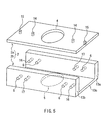
- the heat exchange module 12 shown in FIGS. 4A to 4C is housed in the housing 2 shown in FIG. 5.
- the housing 2 is composed of a lid 2a and a main body 2b.
- the inlet 4 is provided in a central portion of the lid 2a.
- the main body 2b is composed of side plates 13a and 13b opposed to each other, and a bottom plate 13c, and its cross section has a straight-sided U shape.
- the first outlet 5 is provided in a central portion of the bottom plate 13c.
- the side plates 13a and 13b are provided with the second outlets 6.
- injection holesl4 and 15 are formed in the lid 2a, so that a material is injected therethrough upon the formation of the sealing members, which will be described later, and air vents 16 and 17 are formed in the side plates 13a and 13b of the main body 2b.
- the injection holes 14 and 15, the air vents 16 and 17, and the filling of a material with use of these are described later.
- FIGS. 6A to 6C the installation of the heat exchange module 12 in the housing 2 is carried out in a manner such that the tube 1 central axis direction is oriented in a longitudinal axis direction of the housing 2. Further, in this step, exposed portions of the fixing members 9a to 9d in the tube groups 10 on surfaces of the heat exchange module 12 are brought into close contact with or bonded with inner surfaces of the housing 2.
- FIG. 6A indicates the lid 2a with dotted lines for the purpose of illustration.
- FIG. 6C indicates the housing 2 entirely with dotted lines.
- This step of bringing the exposed portions on the surfaces into close contact with the inner surfaces of the housing 2 or bonding the same thereto may be carried out to an extent such that in the later-described step of forming the sealing members by filling a resin material (see FIGS. 7 and 8), the resin material should not flow into the gaps 7.
- the sealing members 3a to 3c are formed in the housing 2 in which the heat exchange module 12 is installed, by filling a resin material. More specifically, as shown in FIG. 7, first the housing in which the heat exchange module 12 is installed is attached to a jig 18.
- the jig 18 is composed of a main body plate 18a, and a pair of pressure plates 18b and 18c that sandwich the housing 2 so as to stop up the opposed openings of the housing 2. Packings 19 are provided between the pressure plate 18b and the housing 2 and between the pressure plate 18b and the housing 2. With this configuration, the resin material is prevented from leaking out via the openings of the housing 2, as well as is prevented from intruding in the tubes 1. It should be noted that 25 denotes a tube, which will be described later.
- the jig 18 is configured to be rotational around an axis extending from the center of the inlet 4 to the center of the first outlet 5. As described later, the filing of the resin material is carried out while the jig 18 is rotated. Further, on an upper face of the housing 2, a mask 20 is applied over a top face of the housing 2 to prevent the intrusion of the resin material through the inlet 4. However, holes are provided in the mask 20 so that the injection holes 14 and 15 are not stopped up.
- an injection pot 21 is attached on the top face of the housing 2.
- the injection pot 21 includes a flow path 24 for guiding a resin material 23 filled in the injection pot 21 to the injection holes 14 and 15.
- 22 denotes a lid of the injection pot.
- the heat exchange module 12 is shown as viewed from a side thereof.
- the injection hole 15 shown in the left-side part of the drawing is formed so as to be connected to interstices around the tubes 1 between the opening of the housing on the left side as viewed in the drawing and the outer fixing member (9a or 9d) of each tube group 10 on the left side as viewed in the drawing (hereinafter referred to as "first housing space”).
- the injection hole 15 shown in the right-side part of the drawing is formed so as to be connected to interstices around the tubes 1 between the opening of the housing on the right side as viewed in the drawing and the fixing member (9d or 9a) of each outer tube group 10 on the right side as viewed in the drawing (hereinafter referred to as "second housing space”).
- the injection holes 14 are formed so as to be connected with a space (hereinafter referred to as "third housing space”) positioned between the two inner fixing members 9b and 9c of each tube group 10 in the housing 2.
- the resin material 23 when the resin material 23 is filled into the injection pot 21, the resin material 23 intrudes into the inside of the housing through the injection holes 14 and 15.
- the portions of the fixing members 9a to 9d of each tube group 10 that are exposed on surfaces of the heat exchange module 12 are bonded to inner surfaces of the housing 2. Therefore, the resin material is filled in only the first, second, and third housing spaces, whereby the gaps 7 are formed.
- the filling of the resin material is carried out by rotating the jig 18 as described above, which causes the housing 2 and the injection pot 21 to rotate also. Therefore, centrifugal force developed by the foregoing rotation is applied to the resin material filled in the housing 2. As a result, a flow path 8 in a columnar shape as shown in FIG. 2 is formed with the resin material filled in the third housing space.
- the first and second housing spaces are completely closed spaces when the injection of the resin material through the injection holes 15 is started. Therefore, without an escape through which air goes out, the injection of the resin material over a certain extent is inhibited.
- the air vent 16 connected to the first housing space and the air vent 17 connected to the third housing space are provided in the side plate 13a of the housing (see FIG. 5).
- the air vent 16 connected to the second housing space and the air vent 17 connected to the third housing space are provided in the side plate 13b of the housing (see FIG. 5).
- the air vents 16 and 17 in each side plate are connected with each other via a tube 25.
- the injection of the resin material with use of the injection pot 21 shown in FIG. 8 is carried out until the first and second housing spaces are filled with the resin material and the flow path 8 (see FIGS. 1A to 1C and 2) matched with the inlet 4 and the first outlet 5 is formed in the third housing space.
- the rotation of the jig 18 is stopped when the fluidity of the resin material thus filled decreases and the shape of the flow path 8 is maintained.
- the first sealing member 3a is formed in the first housing space, while the second sealing member 3b is formed in the second housing space.
- the third sealing member 3c is formed in the third housing space, whereby the flow path 8 is formed also.
- the three sealing members 3a and 3c are formed through one step of the filling of resin material.
- the sealing members 3a to 3c preferably are formed to have a two-layer structure by injecting resin materials of different types successively.
- resin materials for instance, a polyurethane resin and an epoxy resin can be used.
- the close contact property, the adhesivity, and the compatibility can be improved between the sealing members 3a to 3c and the tubes 1, as well as between the sealing members 3a to 3c and the housing.
- a polyurethane resin is used as a resin material. Further, the injection of a polyurethane resin is carried out by setting the rotation rate of the jig 18 to 1500 rpm to 3000 rpm, the amount to be injected to 20 ml to 100 ml, the inner temperature of the injection pot 21 to room temperature (25°C) to 60°C, and the time of rotation of the jig 18 to 30 min to 360 min.
- the plurality of tubes 1 can be arranged simply, easily, and regularly at uniform pitches, and this process can be carried out within a short time. Therefore, by the heat exchanger manufacturing method of the present invention, a multi-tubular heat exchanger can be provided at a lower production cost. Accordingly, it is possible to make a contribution to the cost reduction of an apparatus in which the obtained heat exchanger is used, for instance, in the cost reduction of a heart-lung machine.
- the heat exchanger manufacturing method of the present invention can be used for manufacturing a heat exchanger other than that shown in FIGS. 1A to 1C and 2, for instance, for manufacturing a heat exchanger shown in FIGS. 10A, 10B, and 11.
- only two fixing members may be disposed in the manufacture of the tube group 10 shown in FIGS. 3A to 3C.
- the resin material for forming the sealing members may be filled only in interstices around the tubes between the openings of the housing and the fixing members.
- a resin material may be filled so that a flow path that guides the second fluid introduced through the inlet toward the outlet is formed in a space between the two fixing members of each tube group in the housing.
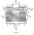
- FIG. 9 is a cross-sectional view illustrating a configuration of an example of a heart-lung machine according to the present invention. It should be noted that among the reference numerals shown in FIG. 9, the same numerals as those shown in FIGS. 1A to 1C and 2 designate the same members as those shown in FIGS. 1A to 1C and 2.
- a heart-lung machine includes a heat exchanger 30 and an artificial lung 40, which are installed in a housing 31.
- the housing 31 includes a cold/hot water introduction path 32 through which cold/hot water for heat exchange is introduced, a cold/hot water discharge path 33 through which the cold/hot water is discharged, a gas introduction path 34 through which oxygen gas is introduced, and a gas discharge path 35 through which carbon dioxide and the like removed from blood is discharged.
- the heat exchanger 30 has the same configuration as that shown in FIGS. 1A to 1C and 2.
- cold/hot water flows through the tubes 1, blood of a patient flows through the flow path 8.
- a pipe 41 for guiding blood is connected to the inlet 4 provided in the housing 2 of the heat exchanger 30.
- the artificial lung 40 includes a plurality of hollow fiber films 37 and a pair of sealing members 38.
- the pair of sealing members 38 seal both ends of the plurality of hollow fiber films 37 so that blood does not intrude into the gas introduction path 34 and the gas discharge path 35.
- the sealing with use of the sealing members 38 is carried out so that both the ends of the hollow fiber films 37 are exposed. With this configuration, the gas introduction path 34 and the gas discharge path 35 are connected with each other via the hollow fiber films 37.
- a space in the artificial lung 40 in which the sealing members 38 are not present forms a blood flow path 39, in which the hollow fiber films 37 are exposed. Still further, a blood inlet side of the blood flow path 39 is connected to an outlet side of the flow path 8 of the heat exchanger 30.
- the blood subjected to heat exchange while running through the flow path 8 flows into the blood flow path 39, where the blood is brought into contact with the hollow fiber films 37.
- oxygen gas running through the hollow fiber film 37 is taken into the blood.
- the blood having captured oxygen gas is discharged to the outside via a blood discharging outlet 36 provided in the housing 31, and then returned to the patient.
- carbon dioxide in the blood is taken into the hollow fiber films 37 and thereafter discharged through the gas discharge path 35.
- the temperature adjustment of blood is carried out by the heat exchanger 30, and blood thus subjected to temperature adjustment is subjected to gas exchange by the artificial lung 40.
- the sealing is leaky in the heat exchanger 30 and cold/hot water running through the tubes 1 leaks out, the leaked cold/hot water is retained in the gaps 7, and thereafter discharged to the outside through the second outlets 6 of the heat exchanger 30. Therefore, the sealing leakage can be detected, and contamination of blood with the cold/hot water can be prevented.
- the present invention it is possible to provide a heat exchanger and a heart-lung machine capable of preventing a fluid running through the inside of tubes or a fluid running over surfaces of tubes from being contaminated due to sealing leakage, and to provide a method for manufacturing a heat exchanger with which the production cost can be reduced.
- the heat exchanger of the present invention can be used as a heat exchanger for medical use, which could possibly cause loss of life if sealing leakage occurs.
Landscapes
- Health & Medical Sciences (AREA)
- Engineering & Computer Science (AREA)
- Heart & Thoracic Surgery (AREA)
- Vascular Medicine (AREA)
- General Health & Medical Sciences (AREA)
- Physics & Mathematics (AREA)
- Biomedical Technology (AREA)
- Hematology (AREA)
- Life Sciences & Earth Sciences (AREA)
- Animal Behavior & Ethology (AREA)
- Anesthesiology (AREA)
- Public Health (AREA)
- Veterinary Medicine (AREA)
- Cardiology (AREA)
- Thermal Sciences (AREA)
- Mechanical Engineering (AREA)
- General Engineering & Computer Science (AREA)
- Emergency Medicine (AREA)
- Urology & Nephrology (AREA)
- Geometry (AREA)
- External Artificial Organs (AREA)
- Heat-Exchange Devices With Radiators And Conduit Assemblies (AREA)
Abstract


Description
- The present invention relates to a heat exchanger, particularly to a heat exchanger used in medical equipment such as a heart-lung machine, a method for manufacturing the same, and a heart-lung machine in which the heat exchanger is used.
- In heart surgery that involves cardiac arrest in a patient, a heart-lung machine is used for taking over the functions of respiration and circulation during the cardiac arrest. Further, during the surgery, it is necessary to lower the patient's temperature and maintain the same so that the patient's oxygen consumption should decrease. For this purpose, the heart-lung machine is equipped with a heat exchanger to control the temperature of blood taken out of the patient.
- As such a medical-use heat exchanger, a bellows-type heat exchanger (see Non-Patent
Document 1, for instance), a multi-tubular heat exchanger (seePatent Document 1, for instance), etc., have been known conventionally. Among these, the multi-tubular heat exchanger has a larger area used for heat exchange as compared with the bellows-type heat exchanger with the same device capacity, and hence, it has the advantage of a higher heat exchange ratio as compared with the bellows-type heat exchanger. Accordingly, the use of the multi-tubular heat exchanger is considered to contribute to the downsizing of the heart-lung machine. - Here, the conventional multi-tubular heat exchanger is described specifically with reference to FIGS. 10A, 10B, and 11. FIGS. 10A and 10B show a conventional multi-tubular heat exchanger. FIG. 10Ais a top view of the same, while FIG. 10B is a front view of the same. FIG. 11 is a perspective view illustrating tubes and sealing members composing the conventional multi-tubular heat exchanger shown in FIGS. 10A and 10B. The heat exchanger shown in FIGS. 10A and 10B is a heat exchanger for medical use.
- As shown in FIGS. 10A, 10B, and 11, the conventional multi-tubular heat exchanger includes a plurality of
tubes 31 through which blood taken out of a patient flows, ahousing 32 for housing thetubes 31, and sealingmembers members tubes 31 on opposite sides, respectively, so as to seal cold/hot water (heat medium) flowing over surfaces of thetubes 31. Besides, thetubes 31 are fixed in thehousing 32 by the sealingmembers tubes 31 are arrayed regularly at uniform pitches as shown in FIGS. 10A, 10B, and 11 to improve the heat exchange ratio. It should be noted that arrows in FIG. 10Aindicate a direction of blood flow, and arrows in FIG. 10B indicate a direction of flow of cold/hot water. - A space between the sealing
members housing 32 constitutes a flow path through which cold/hot water flows. Besides, the sealingmembers housing 32 and external faces of thetubes 31, whereby the sealing of cold/hot water flowing the flow path is achieved: Thehousing 32 is provided with aninlet 34 and anoutlet 35 for cold/hot water whose positions are matched to positions of mouths of the flow path for cold/hot water. - Thus, in the heat exchanger shown in FIGS. 10A, 10B, and 11, when blood flows in through the
tubes 31 while cold/hot water flows in through theinlet 34, heat exchange occurs between blood and cold/hot water via tube walls of thetubes 31, whereby the temperature of blood is adjusted. Besides, mouths of thetubes 31 on the blood outlet side are connected to an artificial lung (not shown), and blood thus subjected to temperature adjustment is fed to the artificial lung. In the artificial lung, addition of oxygen and discharge of carbon dioxide are carried out on the blood. - The heat exchanger shown in FIGS. 10A, 10B, and 11 is formed with the following procedure. First, a plate (not shown) provided with a plurality of through holes is prepared, and
tubes 31 are inserted into the through holes (not shown) of the plate, respectively. Then, thetubes 31 in this state are housed in ahousing 32, and the first potting is performed. Further, in a state in which the plate is removed, the second potting is performed, whereby the sealingmembers
Patent document 1:JP 11(1999)-47269 A
Non-patent document 1: "TRILIUM AFFINITY NT Oxygenator" Medtronic, 2000, U.S. - However, the multi-tubular heat exchanger as shown in FIGS. 10A, 10B, and 11 has an advantage of a higher heat exchange ratio as compared with that of the bellows-type heat exchanger, whereas it has a problem of a higher production cost as compared with the cost of the bellows-type heat exchanger since the manufacture of the same requires many steps to achieve regular arrangement of the
tubes 31 at uniform pitches as described above. Such a higher cost of the heat exchanger increases the cost of the heart-lung machine, thereby resulting in an increase in expenses for medical care, i.e., an increase in the burden on a patient. - Further, in the multi-tubular heat exchanger as shown in FIGS. 10A, 10B, and 11, the cold/hot water (heat medium) normally has a pressure higher than that of blood. Therefore, when the sealing
members tubes 31, the artificial lung (not shown) connected to mouths of thetubes 31 on the blood outgoing side, etc., thereby contaminating blood. - Accordingly, it is an object of the present invention to provide a heat exchanger capable of solving the above-described problem and preventing the fluid flowing through the inside of the tubes or the fluid flowing over surfaces of the tubes from being contaminated by sealing leakage, and to provide a method for manufacturing a heat exchanger with which a decrease in the production cost can be achieved.
- In order to achieve the foregoing problems, a heat exchanger according to the present invention includes at least a plurality of tubes through which a first fluid passes, a housing in which the tubes are installed, and sealing members for sealing a second fluid that flows over surfaces of the tubes, and is characterized as follows: the housing includes an inlet for introducing the second fluid into the housing, as well as a first outlet and a second outlet for discharging the second fluid out of the housing; the tubes are arranged in parallel with one another in the housing; the sealing members include at least a first sealing member positioned on one of end sides of the tubes, a second sealing member positioned on the other end side of the tubes, and a third sealing member positioned between the first and second sealing members; the third sealing member is provided so that a gap is provided between the first sealing member and the third sealing member while another gap is provided between the second sealing member and the third sealing member, and that a flow path is formed therein for guiding the second fluid introduced through the inlet toward the first outlet; and the second outlet is provided in the housing so as to be connected to the gaps.
- Further, in order to achieve the above-described object, a heat exchanger manufacturing method according to the present invention is a method for manufacturing a heat exchanger that includes a plurality of tubes through which a first fluid passes and a housing in a tubular shape, wherein an inlet for introducing the second fluid into the housing and an outlet for discharging the second fluid are provided in sidewalls of the housing, and the method includes at least the steps of: (a) arranging the tubes in parallel with one another at intervals in a manner such that central axes of the tubes are positioned on the same plane; (b) forming a tube group by fixing and integrating the tubes in the arrayed state with use of band-like fixing members that are extended in a direction perpendicular to the central axes of the tubes so as to encircle all the tubes, the fixing members being at least two arranged at intervals along a direction of the central axes; (c) forming a heat exchange module by preparing a plurality of the tube groups and stacking the same, wherein the fixing members of each tube group are brought into close contact, in the direction of the central axes, with the fixing members of another tube groups immediately above and below the foregoing group; (d) installing the heat exchange module in the housing in a manner such that the direction of the central axes is directed in a longitudinal axis direction of the housing, wherein exposed portions of the fixing members in each tube group on surfaces of the heat exchange module are brought into close contact with or bonded with inner surfaces of the housing; and (e) filling a resin material in a manner such that a flow path for guiding the second fluid introduced through the inlet toward the outlet is formed in a space positioned between the two fixing members of each tube group in the housing, or in a manner such that the resin material is filled in interstices around the tubes between openings of the housing and the fixing members of the tube groups.
- Still further, in order to achieve the above-described object, a heart-lung machine according to the present invention is characterized by including the above-described heat exchanger according to the present invention.
- With the foregoing characteristics, according to the present invention, a heat exchanger is capable of preventing the fluid flowing through the inside of the tubes or the fluid flowing over surfaces of the tubes from being contaminated by sealing leakage, and it is possible also to provide a heat exchanger manufacturing method with which a multi-tubular heat exchanger can be manufactured at a lower production cost.
-
- [FIG. 1] FIGS. 1A to 1C show a configuration of an example of a heat exchanger according to the present invention. FIG. 1A is a top view thereof,
- FIG. 1B is a side view thereof, and FIG. 1C is a front view thereof.
- [FIG. 2] FIG. 2 is a partially cut-away perspective view showing the inside of a housing in the heat exchanger shown in FIGS. 1A to 1C.
- [FIG. 3] FIGS. 3A to 3C show a group of tubes composing a heat exchange module. FIG. 3Ais a top view thereof, FIG. 3B is a front view thereof, and FIG. 3C is a perspective view thereof.
- [FIG. 4] FIGS. 4Ato 4C show the heat exchange module. FIG. 4Ais a top view thereof, FIG. 4B is a front view thereof, and FIG. 4C is a perspective view thereof.
- [FIG. 5] FIG. 5 is an exploded perspective view of a housing.
- [FIG. 6] FIGS. 6A to 6C show the housing shown in FIG. 5 in which the heat exchange module shown in FIGS. 4A to 4C is disposed. FIG. 6Ais a top view thereof, FIG. 6B is a front view thereof, and FIG. 6C is a perspective view thereof.
- [FIG. 7] FIG. 7 is a top view illustrating the housing attached to a jig so that sealing members are formed.
- [FIG. 8] FIG. 8 is a cross-sectional view illustrating a step of forming the sealing members.
- [FIG. 9] FIG. 9 is a cross-sectional view illustrating a configuration of an example of a heart-lung machine according to the present invention.
- [FIG. 10] FIGS. 10A and 10B show a conventional multi-tubular heat exchanger. FIG. 10Ais a top view thereof, and FIG. 10B is a front view thereof.
- [FIG. 11] FIG. 11 is a perspective view illustrating tubes and sealing members composing the conventional multi-tubular heat exchanger shown in FIG. 10.
- As described above, a heat exchanger according to the present invention includes at least a plurality of tubes through which a first fluid passes, a housing in which the tubes are installed, and sealing members for sealing a second fluid that flows over surfaces of the tubes, and is characterized as follows: the housing includes an inlet for introducing the second fluid into the housing, as well as a first outlet and a second outlet for discharging the second fluid out of the housing; the tubes are arranged in parallel with one another in the housing; the sealing members include at least a first sealing member positioned on one of end sides of the tubes, a second sealing member positioned on the other end side of the tubes, and a third sealing member positioned between the first and second sealing members; the third sealing member is provided so that a gap is provided between the first sealing member and the third sealing member while another gap is provided between the second sealing member and the third sealing member, and that a flow path is formed therein for guiding the second fluid introduced through the inlet toward the first outlet; and the second outlet is provided in the housing so as to be connected to the gaps. Further, a heart-lung machine according to the present invention is characterized by including therein the above-described heat exchanger according to the present invention.
- The heat exchanger according to the present invention preferably is embodied so that the flow path for the second fluid is formed in a columnar shape, the inlet and the first outlet are formed in a round shape, and mouths of the flow path for the second fluid are matched with the inlet and the first outlet, respectively.
- The heat exchanger according to the present invention preferably is embodied so that the tubes are arranged so that in a cross-sectional plane perpendicular to a direction of central axes of the tubes, a figure bounded by lines meeting at cross-sectional centers of three neighboring tubes is an equilateral triangle.
- In the heat exchanger according to the present invention, the second fluid passing through the flow path is blood, and the heat exchanger preferably is adapted to form a part of a heart-lung machine.
- A heat exchanger manufacturing method according to the present invention is a method for manufacturing a heat exchanger that includes a plurality of tubes through which a first fluid passes and a housing in a tubular shape, wherein an inlet for introducing the second fluid into the housing and an outlet for discharging the second fluid are provided in sidewalls of the housing, and the method includes at least the steps of: (a) arranging the tubes in parallel with one another at intervals in a manner such that central axes of the tubes are positioned on the same plane; (b) forming a tube group by fixing and integrating the tubes in the arrayed state with use of band-like fixing members that are extended in a direction perpendicular to the central axes of the tubes so as to encircle all the tubes, the fixing members being at least two arranged at intervals along a direction of the central axes; (c) forming a heat exchange module by preparing a plurality of the tube groups and stacking the same, wherein the fixing members of each tube group are brought into close contact, in the direction of the central axes, with the fixing members of another tube groups immediately above and below the foregoing group; (d) installing the heat exchange module in the housing in a manner such that the direction of the central axes is directed in a longitudinal axis direction of the housing, wherein exposed portions of the fixing members in each tube group on surfaces of the heat exchange module are brought into close contact with or bonded with inner surfaces of the housing; and (e) filling a resin material in a manner such that a flow path for guiding the second fluid introduced through the inlet toward the outlet is formed in a space positioned between the two fixing members of each tube group in the housing, or in a manner such that the resin material is filled in interstices around the tubes between openings of the housing and the fixing members of the tube groups.
- The heat exchanger manufacturing method according to the present invention preferably is embodied so that: in the step (b), the fixing members of each tube group are four in number, which are arranged at intervals along the direction of the central axes, two of the four fixing members being inner fixing members and the other two being outer fixing members disposed relatively outward with respect to the two inner fixing members, and two inner fixing members are positioned so that the inlet and the outlet are positioned between the two inner fixing members; and in the step (e), the resin material is filled into a space between the two inner fixing members of each tube group in the housing in a manner such that a flow path for guiding the second fluid introduced through the inlet toward the outlet is formed in the space, and further, the resin material is filled in interstices around the tubes between one of the openings of the housing on one side and the outer fixing member of each tube group on the same side, as well as interstices around the tubes between the other opening of the housing on the other side and the outer fixing member of each tube group on the same side.
- In the foregoing embodiment, it is preferable that the inlet and the outlet are formed, each in a round shape, at positions such that they are opposed to each other, and that in the step (e), the filling of the resin material into the space between the two inner fixing members of each tube group in the housing is carried out by rotating the housing around an axis extending from the center of the inlet to the center of the outlet.
- In the above-described heat exchanger manufacturing method according to the present invention, it is preferable that in the step (c), the stacking of the plurality of tube groups is carried out in a manner such that in a cross-sectional plane perpendicular to the direction of the central axes of the tubes, a figure bounded by lines meeting at the cross-sectional center of each of the tubes in each tube group and the cross-sectional centers of two tubes most adjacent to the foregoing tube in another tube group immediately above or below the foregoing tube group is an equilateral triangle.
- In the above-described heat exchanger manufacturing method according to the present invention, the following is preferred: the steps (a) and (b) are carried out by using an upper die and a lower die, in each of which a plurality of first grooves where the tubes are to be disposed and a second groove orthogonally crossing the first grooves are formed; in the step (a), the arrangement of the tubes is carried out by disposing the tubes in the first grooves in either one of the upper and lower dies; and in the step (b), the integration with use of the fixing members is carried out by joining the upper and lower dies and injecting a resin material into the space formed by the second grooves in the upper and lower dies so that the fixing members are formed by injection molding.
- In the above-described heat exchanger manufacturing method according to the present invention, it is preferable that the resin material used in the step (b) for forming the fixing members by injection molding is a polycarbonate resin or a vinyl chloride resin, and that the resin material used in the step (e) is a polyurethane resin or an epoxy resin.
- The following describes an example of a heat exchanger and a method for manufacturing the heat exchanger according to the present invention, while referring to the drawings. It should be noted that the heat exchanger and the method for manufacturing the heat exchanger according to the present invention are not limited to the examples described below. First, an example of a configuration of the heat exchanger according to the present invention is described, with reference to FIGS. 1A to 1C and 2.
- FIGS. 1A to 1C show a configuration of an example of the heat exchanger according to the present invention. FIG. 1A is a top view thereof, FIG. 1B is a side view thereof, and FIG. 1C is a front view thereof. FIG. 2 is a partially cut-away perspective view showing the inside of a housing in the heat exchanger shown in FIGS. 1A to 1C.
- As shown in FIGS. 1A to 1C, the heat exchanger according to the present embodiment includes a plurality of
tubes 1 through which a first fluid flows, ahousing 2 in which thetubes 1 are installed, and sealingmembers 3a to 3c for sealing a second fluid that flows over surfaces of thetubes 1. - As shown in FIGS. 1A to 1C and 2, the
tubes 1 are arrayed in parallel with one another in thehousing 2. In the example shown in FIGS. 1A to 1C and 2, thetubes 1 are arranged three-dimensionally. More specifically, thetubes 1 are arranged in the following manner such that in a cross-sectional plane perpendicular to a direction of central axes of the tubes 1 (this direction is hereinafter referred to as "tube 1 central axis direction"), a figure bounded by lines meeting at cross-sectional centers of three neighboringtubes 1 is an equilateral triangle; in other words, in a manner such that thetubes 1 in a given row are not aligned vertically with thetubes 1 in another row immediately below the foregoing given row" respectively (see FIG. 1B). - It should be noted that in the present invention, the arrangement of the
tubes 1 is not limited to the example shown in FIGS. 1A to 1C and 2. For instance, thetubes 1 may be arranged so that in a cross section perpendicular to thetube 1 central axis direction, respective cross sections of thetubes 1 are arrayed in a matrix form; in other words, in a manner such that, thetubes 1 in a given row are aligned vertically with thetubes 1 another row immediately below the foregoing given row, respectively. However, with a view to improving the heat exchange ratio, thetubes 1 preferably are arranged in a manner such that thetubes 1 in a given row are not aligned vertically with thetubes 1 in the another row immediately below the foregoing given row, respectively, as shown in FIGS. 1A to 1C and 2. - The
housing 2 includes aninlet 4 for introducing a second fluid into the housing, and afirst outlet 5 for discharging the second fluid from the housing. Theinlet 4 also constitutes an inlet of aflow path 8 for the second fluid, which will be described later, while thefirst outlet 5 also constitutes an outlet of theflow path 8 of the second fluid, which will be described later. - It should be noted that in the example shown in FIGS. 1A to 1C, the
housing 2 is formed in a tubular shape having a rectangular cross section, and theinlet 4 and theoutlet 5 are disposed respectively on sidewalls of the housing that are opposed to each other. Theinlet 4 and thefirst outlet 5 are matched to the mouths of theflow path 8. In the present specification, "theinlet 4 and thefirst outlet 5 are matched to the mouths of theflow path 8" does not exclusively indicate the case where theinlet 4 and thefirst outlet 5 are identical to the mouths of theflow path 8. This description is meant to signify that theinlet 4 and thefirst outlet 5 may be continuous with the mouths of theflow path 8. - In the present invention, the cross-sectional shape of the
housing 2 is not limited to the rectangular shape as shown in FIGS. 1A to 1C, but may be determined appropriately according to the arrangement of thetubes 1. Thehousing 2 may have any cross-sectional shape other than the rectangular shape, such as a polygonal shape, or a round shape. Further, the positions where theinlet 4 and thefirst outlet 5 are formed are not limited particularly. However, with a view to improving the heat exchange ratio, theinlet 4 and thefirst outlet 5 preferably are disposed at opposed positions in thehousing 2, as shown in FIGS. 1A to 1C and 2. - Still further, as shown in FIG. 2, the sealing members include a
first sealing member 3a positioned on one of end sides of thetubes 1, asecond sealing member 3b positioned on the other end side of thetubes 1, and athird sealing member 3c positioned between the first andsecond sealing members tubes 1 from one another is achieved by these first, second, andthird sealing members - The
third sealing member 3c is provided so as to have agap 7 between thefirst sealing member 3a and itself and anothergap 7 between thesecond sealing member 3b and itself. As seen in FIGS. 1A to 1C, theflow path 8 through which the second fluid introduced from theinlet 4 to thehousing 2 is guided toward thefirst outlet 5 is formed by thethird sealing member 3c. Thethird sealing member 3c functions to seal the second fluid. Still further,second outlets 6 are provided in thehousing 2 so as to be continuous with the gaps 7 (see FIG. 1B). - Thus, in the heat exchanger of the present invention shown in FIGS. 1A to 1C, the sealing members positioned at ends of the tubes 1 (the first and
second sealing members flow path 8 for the second fluid (thethird sealing member 3c) are provided separately. Further, thegaps 7 are formed between thefirst sealing member 3a and theflow path 8 for the second fluid and between thesecond sealing member 3b and theflow path 8 for the second fluid. - Therefore, in the case where, for example, the second fluid leaks due to leakage of the
third sealing member 3c, the second fluid having leaked is retained temporarily in thegaps 7, and thereafter is discharged through thesecond outlets 6 to outside the heat exchanger. In the case where the first fluid leaks due to leakage of thefirst sealing member 3a or thesecond sealing member 3b, the first fluid having leaked is retained temporarily in thegap 7, and thereafter is discharged through thesecond outlets 6 to outside the heat exchanger. - In other words, in the heat exchanger in the example shown in FIGS. 1A to 1C, a safety mechanism is provided to prevent the first fluid flowing through the
tubes 1 from intruding into theflow path 8 and to prevent the second fluid flowing through theflow path 8 from intruding into thetubes 1. Further, by monitoring the discharge of fluid through thesecond outlets 6, the detection of sealing leakage can be performed. Still further, by checking discharged fluid, it can be determined which sealing member has been leaking. - Here, a case where the heat exchanger shown in FIGS. 1A to 1C is used in a heart-lung machine is considered. First, an example in which cold/hot water flows through the
tubes 1 and blood flows through theflow path 8 is considered. In this example, when the first, second, andthird sealing members flow path 8 since it has a higher pressure. However, in this case, the cold/hot water having leaked out of the first or second sealingmember gap 7 temporarily, and is discharged through thesecond outlets 6 to outside the heat exchanger. Thus, the sealing leakage can be detected, and the occurrence of blood contamination as described in the "background art" section can be prevented. - Further, in such an embodiment in which blood flows through the
flow path 8, the cross-sectional shape of theflow path 8 and the shapes of theinlet 4 and thefirst outlet 5 preferably are round, as in the example shown in FIGS. 1A to 1C and 2. This is because by forming them in round shapes, the occurrence of thrombus can be suppressed at theflow path 8, theinlet 4, and thefirst outlet 5. It should be noted that in the present invention, the cross-sectional shape of theflow path 8 and the shapes of theinlet 4 and thefirst outlet 5 may be a rectangular shape, or another polygonal shape. - Next, an example in which blood flows through the
tubes 1 while cold/hot water flows through theflow path 8 like the conventional heat exchanger shown in FIGS. 10A, 10B, and 11 is considered. In this example also, since the cold/hot water has a higher pressure, the cold/hot water outflows when the first, second, andthird sealing members tubes 1 on the blood inlet side and the artificial lung connected to the outlet side of thetubes 1. However, in this case also, the cold/hot water having leaked through thethird sealing member 3c is retained in thegaps 7 temporarily, and is discharged through thesecond outlets 6 to outside the heat exchanger. Thus, in this example also, the sealing leakage can be detected, and the occurrence of blood contamination as described in the "background art" section can be suppressed. - As described above, if the heat exchanger shown in FIGS. 1A to 1C is applied in the heart-lung machine, outflow of cold/hot water due to sealing leakage can be detected. Further, as compared with the conventional heat exchanger shown in FIGS. 10A, 10B, and 11, the possibility of blood contamination can be decreased to a significantly low level.
- The following describes an example of a method for manufacturing a heat exchanger according to the present invention while referring to FIGS. 3 to 8. It should be noted that the heat exchanger obtained by the following manufacturing method is identical to the heat exchanger shown in FIGS. 1A to 1C and 2, and includes a plurality of
tubes 1 through which a first fluid passes, atubular housing 2, and sealingmembers 3a to 3c. On sidewalls of thehousing 2, aninlet 4 for introducing a second fluid into the housing, and afirst outlet 5 for discharging the second fluid therefrom are formed. Still further, the sealing members are composed of three sealingmembers 3a to 3c that are formed withgaps 7 being provided therebetween. Still further, on sidewalls of thehousing 2,second outlets 6 continuous with thegaps 7 are formed also. - FIGS. 3A to 3C show a group of tubes composing a heat exchange module. FIG. 3Ais a top view thereof, FIG. 3B is a front view thereof, and FIG. 3C is a perspective view thereof. FIGS. 4A to 4C show the heat exchange module. FIG. 4Ais a top view thereof, FIG. 4B is a front view thereof, and FIG. 4C is a perspective view thereof. FIG. 5 is an exploded perspective view of a housing. FIGS. 6A to 6C show the housing shown in FIG. 5 in which the heat exchange module shown in FIGS. 4A to 4C is disposed. FIG. 6Ais a top view thereof, FIG. 6B is a front view thereof, and FIG. 6C is a perspective view thereof. FIG. 7 is a top view illustrating the housing attached to a jig so that sealing members are formed. FIG. 8 is a cross-sectional view illustrating a step of forming the sealing members.
- First, as shown in FIGS. 3A to 3C, a plurality of
tubes 1 are arranged in parallel at intervals so that central axes of thetubes 1 are positioned on the same plane. Further, thetubes 1 are fixed and integrated in the arrayed state described above with use of band-like fixing members 9a to 9d extended in a direction perpendicular to thetube 1 central axis direction so as to encircle all the tubes. As a result, thetube group 10 is obtained. - In the example shown in FIGS. 3A to 3C, the formation of the
tube group 10 is performed by insert molding that utilizes an upper die and a lower die (not shown). More specifically, in each of the upper die and the lower die, a plurality of first grooves (not shown) and a plurality of second grooves (not shown) are formed. - The first grooves in the upper die and the lower die are formed so that the
tubes 1 can be disposed therein. Further, the first grooves in the upper die and the first grooves in the lower die are matched to each other when the upper and lower dies are joined. Therefore, by disposing thetubes 1 in the first grooves in either one of the upper and lower dies, the positioning of thetubes 1 is achieved. - The second grooves are formed so as to cross the first grooves orthogonally Further, the second grooves in the upper die and the second grooves in the lower die are matched to each other when the upper and lower are joined, and form cavities that are used for forming the fixing
members 9a to 9d. - Therefore, in the example of FIGS. 3A to 3C, the arrangement of the
tubes 1 is achieved by, in either one of the upper and lower dies, disposing thetubes 1 in the plurality of first grooves formed in the die, respectively. By joining the upper and lower dies and injecting a resin material for forming the fixingmembers 9a to 9b into spaces formed by the second grooves in the upper and lower dies, the fixingmembers 9a to 9d are formed by injection molding. Through this injection molding, thetubes 1 are fixed with each other in an arranged state and integrated, as shown in FIGS. 3A to 3C. - It should be noted that examples of the resin material used for forming the fixing members include resins for injection molding that exhibit excellent fluidity and small shrinkage after molding, such as polycarbonate resins, polyamide resins, polyurethane resins, polypropylene resins, and poly(vinyl chloride) resins. Among these, a polycarbonate resin or a vinyl chloride resin is used preferably. This is because, as will be described later (see FIGS. 4A to 4C), in the present example, the fixing
members 9a to 9d of thetube groups 10 neighboring to each other in the vertical direction are placed in close contact with one another in the process of forming a heat exchange module, and a polycarbonate resin or a vinyl chloride resin facilitates achieving the close contact property. - In the example shown in FIGS. 3A to 3C, the fixing members are four in total, which are the fixing
members 9a to 9d (inner fixing members outer fixing members inner fixing members tube 1 central axis direction. As seen in FIG. 3B, a plurality of recessedportions 11 are formed in the fixingmembers 9a to 9d so as to facilitate the formation of a heat exchange module, which will be described later. As shown in FIGS. 3A to 3C, a plurality of thetube groups 10 are to be formed. - Further, in the example shown in FIGS. 3A to 3C, the
inner fixing members inlet 4 and the first outlet 5 (see FIGS. 1A to 1C and 2) are positioned in the space between the fixingmembers members inlet 4 as well as than the diameter of the first outlet so that theinlet 4 and thefirst outlet 5 are positioned between the fixingmembers - Still further, a space between the outer fixing
member 9a and theinner fixing member 9b and a space between the outer fixingmember 9d and the inner fixingmember 9c form thegaps 7, which are thegap 7 between thethird sealing member 3c and thefirst sealing member 3a and thegap 7 between thethird sealing member 3c and thesecond sealing member 3b (see FIGS. 1A to 1C and 2). Therefore, the interval between the fixingmembers members gaps 7 to be formed are allowed to exhibit the above-described function and that the heat exchanger is not made bulky. - Next, as shown in FIGS. 4A to 4C, the
heat exchange module 12 is formed by stacking a plurality of thetube groups 10 as shown in FIGS. 4A to 4C. Here, the stacking of the plurality oftube groups 10 is performed in a manner such that the fixingmembers 9a to 9d of eachtube group 10 are brought into close contact, in thetube 1 central axis direction, with the fixingmembers 9a to 9d of anothertube groups 10 immediately above and below the foregoinggroup 10. - More specifically, in the example shown in FIGS. 4Ato 4C, the stacking of the plurality of
tube groups 10 is performed so that the fixingmember 9a of each of thetube groups 10 is brought into close contact with the fixingmember 9d of anothertube groups 10 immediately above and below the foregoing group, and likewise, the fixingmembers tube group 10 are brought into close contact with the fixingmembers tube groups 10 immediately above and below the foregoing group, respectively. By so doing, in theheat exchange module 12 shown in FIGS. 4A to 4C, ends of thetubes 1 in thetube groups 10 are aligned, and side faces of the fixingmembers 9a to 9d of thetube groups 10 fall in the same planes. It should be noted that it is intended by bringing the fixingmembers 9a to 9d of the vertically neighboringtube groups 10 into close contact with one another: namely, in a sealing member forming process (see FIGS. 7 and 8) by filling a resin material, which will be described later, the resin material is to be prevented from flowing into thegaps 7. - Further, in the example of FIGS. 4Ato 4C, the stacking of the plurality of
tube groups 10 is performed in a manner such that thetubes 1 composing eachtube group 10 are fit in the recessedportions 11 provided in the fixingmembers 9a to 9d ofother tube groups 10 immediately above and below the foregoinggroup 10. As a result, as shown in FIGS. 1A to 1C and 2, in a cross-sectional plane perpendicular to thetube 1 central axis direction, a figure bounded by lines meeting at the cross-sectional center of each of thetubes 1 in each tube group and the cross-sectional centers of two tubes most adjacent to the foregoingtube 1 in another tube group immediately above or below the foregoing tube group is an equilateral triangle. - Next, the
heat exchange module 12 shown in FIGS. 4A to 4C is housed in thehousing 2 shown in FIG. 5. In the example shown in FIG. 5, thehousing 2 is composed of alid 2a and amain body 2b. In a central portion of thelid 2a, theinlet 4 is provided. Themain body 2b is composed ofside plates bottom plate 13c, and its cross section has a straight-sided U shape. In a central portion of thebottom plate 13c, thefirst outlet 5 is provided. Theside plates second outlets 6. - Further, injection holesl4 and 15 are formed in the
lid 2a, so that a material is injected therethrough upon the formation of the sealing members, which will be described later, andair vents side plates main body 2b. The injection holes 14 and 15, the air vents 16 and 17, and the filling of a material with use of these are described later. - Further, as shown in FIGS. 6A to 6C, the installation of the
heat exchange module 12 in thehousing 2 is carried out in a manner such that thetube 1 central axis direction is oriented in a longitudinal axis direction of thehousing 2. Further, in this step, exposed portions of the fixingmembers 9a to 9d in thetube groups 10 on surfaces of theheat exchange module 12 are brought into close contact with or bonded with inner surfaces of thehousing 2. It should be noted that FIG. 6A indicates thelid 2a with dotted lines for the purpose of illustration. Further, FIG. 6C indicates thehousing 2 entirely with dotted lines. - In the example of FIGS. 6A to 6C, the exposed portions of the fixing
members 9a to 9d in thetube groups 10 on surfaces of theheat exchange module 12 are bonded with the inner surfaces of the housing 2 (inner surfaces of thelid 2a and themain body 2b). An adhesive used herein is, for instance, a urethane-based adhesive or an epoxy-based adhesive. - It should be noted that in the present embodiment, it is not necessary to bring all the exposed portions of the fixing
members 9a to 9d on surfaces of theheat exchange module 12 into close contact with the inner surfaces of the housing, or to bond the same thereto. This step of bringing the exposed portions on the surfaces into close contact with the inner surfaces of thehousing 2 or bonding the same thereto may be carried out to an extent such that in the later-described step of forming the sealing members by filling a resin material (see FIGS. 7 and 8), the resin material should not flow into thegaps 7. - Next, as shown in FIGS. 7 and 8, the sealing
members 3a to 3c (see FIGS. 1A to 1C and 2) are formed in thehousing 2 in which theheat exchange module 12 is installed, by filling a resin material. More specifically, as shown in FIG. 7, first the housing in which theheat exchange module 12 is installed is attached to ajig 18. - The
jig 18 is composed of amain body plate 18a, and a pair ofpressure plates housing 2 so as to stop up the opposed openings of thehousing 2.Packings 19 are provided between thepressure plate 18b and thehousing 2 and between thepressure plate 18b and thehousing 2. With this configuration, the resin material is prevented from leaking out via the openings of thehousing 2, as well as is prevented from intruding in thetubes 1. It should be noted that 25 denotes a tube, which will be described later. - Further, the
jig 18 is configured to be rotational around an axis extending from the center of theinlet 4 to the center of thefirst outlet 5. As described later, the filing of the resin material is carried out while thejig 18 is rotated. Further, on an upper face of thehousing 2, amask 20 is applied over a top face of thehousing 2 to prevent the intrusion of the resin material through theinlet 4. However, holes are provided in themask 20 so that the injection holes 14 and 15 are not stopped up. - Next, as shown in FIG. 8, an
injection pot 21 is attached on the top face of thehousing 2. Theinjection pot 21 includes aflow path 24 for guiding aresin material 23 filled in theinjection pot 21 to the injection holes 14 and 15. Here, 22 denotes a lid of the injection pot. It should be noted that in FIG. 8, theheat exchange module 12 is shown as viewed from a side thereof. - Further, as seen from FIG. 8, the
injection hole 15 shown in the left-side part of the drawing is formed so as to be connected to interstices around thetubes 1 between the opening of the housing on the left side as viewed in the drawing and the outer fixing member (9a or 9d) of eachtube group 10 on the left side as viewed in the drawing (hereinafter referred to as "first housing space"). On the other hand, theinjection hole 15 shown in the right-side part of the drawing is formed so as to be connected to interstices around thetubes 1 between the opening of the housing on the right side as viewed in the drawing and the fixing member (9d or 9a) of eachouter tube group 10 on the right side as viewed in the drawing (hereinafter referred to as "second housing space"). Further, the injection holes 14 are formed so as to be connected with a space (hereinafter referred to as "third housing space") positioned between the twoinner fixing members tube group 10 in thehousing 2. - Therefore, when the
resin material 23 is filled into theinjection pot 21, theresin material 23 intrudes into the inside of the housing through the injection holes 14 and 15. Here, as described above, the portions of the fixingmembers 9a to 9d of eachtube group 10 that are exposed on surfaces of theheat exchange module 12 are bonded to inner surfaces of thehousing 2. Therefore, the resin material is filled in only the first, second, and third housing spaces, whereby thegaps 7 are formed. - Further, in the example shown in FIG. 8, the filling of the resin material is carried out by rotating the
jig 18 as described above, which causes thehousing 2 and theinjection pot 21 to rotate also. Therefore, centrifugal force developed by the foregoing rotation is applied to the resin material filled in thehousing 2. As a result, aflow path 8 in a columnar shape as shown in FIG. 2 is formed with the resin material filled in the third housing space. - It should be noted that the first and second housing spaces are completely closed spaces when the injection of the resin material through the injection holes 15 is started. Therefore, without an escape through which air goes out, the injection of the resin material over a certain extent is inhibited. To cope with this, as shown in FIG. 7, the
air vent 16 connected to the first housing space and theair vent 17 connected to the third housing space are provided in theside plate 13a of the housing (see FIG. 5). Further, theair vent 16 connected to the second housing space and theair vent 17 connected to the third housing space are provided in theside plate 13b of the housing (see FIG. 5). Still further, the air vents 16 and 17 in each side plate are connected with each other via atube 25. - The injection of the resin material with use of the
injection pot 21 shown in FIG. 8 is carried out until the first and second housing spaces are filled with the resin material and the flow path 8 (see FIGS. 1A to 1C and 2) matched with theinlet 4 and thefirst outlet 5 is formed in the third housing space. The rotation of thejig 18 is stopped when the fluidity of the resin material thus filled decreases and the shape of theflow path 8 is maintained. - As a result, as shown in FIGS. 1A to 1C and 2, the
first sealing member 3a is formed in the first housing space, while thesecond sealing member 3b is formed in the second housing space. Besides, thethird sealing member 3c is formed in the third housing space, whereby theflow path 8 is formed also. Further, in the present embodiment, the three sealingmembers - Examples of the resin material used for forming the sealing
members 3a to 3c in the present embodiment include thermosetting resins such as silicon resins, polyurethane resins, and epoxy resins. Among these, a polyurethane resin or an epoxy resin is preferred since it has excellent adhesivity to a material used for forming the tubes 1 (for instance, a metal material) and a material used for forming housing 2 (for instance, a resin material such as a polycarbonate resin). - Still further, in the case where the
tubes 1 are formed with a metal material and thehousing 2 is formed with a resin material, the sealingmembers 3a to 3c preferably are formed to have a two-layer structure by injecting resin materials of different types successively. For instance, a polyurethane resin and an epoxy resin can be used. In such an embodiment, the close contact property, the adhesivity, and the compatibility can be improved between the sealingmembers 3a to 3c and thetubes 1, as well as between the sealingmembers 3a to 3c and the housing. - It should be noted that in the example shown in FIG. 8, a polyurethane resin is used as a resin material. Further, the injection of a polyurethane resin is carried out by setting the rotation rate of the
jig 18 to 1500 rpm to 3000 rpm, the amount to be injected to 20 ml to 100 ml, the inner temperature of theinjection pot 21 to room temperature (25°C) to 60°C, and the time of rotation of thejig 18 to 30 min to 360 min. - By using the heat exchanger manufacturing method of the present invention as described above, the plurality of
tubes 1 can be arranged simply, easily, and regularly at uniform pitches, and this process can be carried out within a short time. Therefore, by the heat exchanger manufacturing method of the present invention, a multi-tubular heat exchanger can be provided at a lower production cost. Accordingly, it is possible to make a contribution to the cost reduction of an apparatus in which the obtained heat exchanger is used, for instance, in the cost reduction of a heart-lung machine. - The heat exchanger manufacturing method of the present invention can be used for manufacturing a heat exchanger other than that shown in FIGS. 1A to 1C and 2, for instance, for manufacturing a heat exchanger shown in FIGS. 10A, 10B, and 11. In this case, only two fixing members may be disposed in the manufacture of the
tube group 10 shown in FIGS. 3A to 3C. Further, the resin material for forming the sealing members may be filled only in interstices around the tubes between the openings of the housing and the fixing members. Still further, a resin material may be filled so that a flow path that guides the second fluid introduced through the inlet toward the outlet is formed in a space between the two fixing members of each tube group in the housing. - Next, a heart-lung machine in which the heat exchanger of the present invention is used is described with reference to FIG. 9. FIG. 9 is a cross-sectional view illustrating a configuration of an example of a heart-lung machine according to the present invention. It should be noted that among the reference numerals shown in FIG. 9, the same numerals as those shown in FIGS. 1A to 1C and 2 designate the same members as those shown in FIGS. 1A to 1C and 2.
- As shown in FIG. 9, a heart-lung machine includes a
heat exchanger 30 and anartificial lung 40, which are installed in ahousing 31. Thehousing 31 includes a cold/hotwater introduction path 32 through which cold/hot water for heat exchange is introduced, a cold/hotwater discharge path 33 through which the cold/hot water is discharged, agas introduction path 34 through which oxygen gas is introduced, and agas discharge path 35 through which carbon dioxide and the like removed from blood is discharged. - The
heat exchanger 30 has the same configuration as that shown in FIGS. 1A to 1C and 2. In theheat exchanger 30, cold/hot water flows through thetubes 1, blood of a patient flows through theflow path 8. It should be noted that apipe 41 for guiding blood is connected to theinlet 4 provided in thehousing 2 of theheat exchanger 30. - The
artificial lung 40 includes a plurality ofhollow fiber films 37 and a pair of sealingmembers 38. The pair of sealingmembers 38 seal both ends of the plurality ofhollow fiber films 37 so that blood does not intrude into thegas introduction path 34 and thegas discharge path 35. The sealing with use of the sealingmembers 38 is carried out so that both the ends of thehollow fiber films 37 are exposed. With this configuration, thegas introduction path 34 and thegas discharge path 35 are connected with each other via thehollow fiber films 37. - Further, a space in the
artificial lung 40 in which the sealingmembers 38 are not present forms ablood flow path 39, in which thehollow fiber films 37 are exposed. Still further, a blood inlet side of theblood flow path 39 is connected to an outlet side of theflow path 8 of theheat exchanger 30. - Accordingly, the blood subjected to heat exchange while running through the
flow path 8 flows into theblood flow path 39, where the blood is brought into contact with thehollow fiber films 37. Here, oxygen gas running through thehollow fiber film 37 is taken into the blood. The blood having captured oxygen gas is discharged to the outside via ablood discharging outlet 36 provided in thehousing 31, and then returned to the patient. On the other hand, carbon dioxide in the blood is taken into thehollow fiber films 37 and thereafter discharged through thegas discharge path 35. - Thus, in the heart-lung machine shown in FIG. 9, the temperature adjustment of blood is carried out by the
heat exchanger 30, and blood thus subjected to temperature adjustment is subjected to gas exchange by theartificial lung 40. Here, even if the sealing is leaky in theheat exchanger 30 and cold/hot water running through thetubes 1 leaks out, the leaked cold/hot water is retained in thegaps 7, and thereafter discharged to the outside through thesecond outlets 6 of theheat exchanger 30. Therefore, the sealing leakage can be detected, and contamination of blood with the cold/hot water can be prevented. - With the present invention, it is possible to provide a heat exchanger and a heart-lung machine capable of preventing a fluid running through the inside of tubes or a fluid running over surfaces of tubes from being contaminated due to sealing leakage, and to provide a method for manufacturing a heat exchanger with which the production cost can be reduced. The heat exchanger of the present invention can be used as a heat exchanger for medical use, which could possibly cause loss of life if sealing leakage occurs.
Claims (11)
- A heat exchanger comprising at least a plurality of tubes through which a first fluid passes, a housing in which the tubes are installed, and sealing members for sealing a second fluid that flows over surfaces of the tubes, wherein
the housing includes an inlet for introducing the second fluid into the housing, as well as a first outlet and second outlets for discharging the second fluid out of the housing,
the tubes are arranged in parallel with one another in the housing,
the sealing members include at least a first sealing member positioned on one of end sides of the tubes, a second sealing member positioned on the other end side of the tubes, and a third sealing member positioned between the first and second sealing members,
the third sealing member is provided so that a gap is provided between the first sealing member and the third sealing member while another gap is provided between the second sealing member and the third sealing member, and that a flow path is formed therein for guiding the second fluid introduced through the inlet toward the first outlet, and
the second outlets are provided in the housing so as to be connected to the gaps, respectively. - The heat exchanger according to claim 1, wherein
the flow path for the second fluid is formed in a columnar shape,
the inlet and the first outlet are formed in a round shape, and
mouths of the flow path for the second fluid are matched with the inlet and the first outlet, respectively. - The heat exchanger according to claim 1 or 2, wherein
the tubes are arranged so that in a cross-sectional plane perpendicular to a direction of central axes of the tubes, a figure bounded by lines meeting at cross-sectional centers of three neighboring tubes is an equilateral triangle. - The heat exchanger according to any one of claims 1 to 3, wherein
the second fluid passing through the flow path is blood, and
the heat exchanger is adapted to form a part of a heart-lung machine. - A heat exchanger manufacturing method for manufacturing a heat exchanger that includes a plurality of tubes through which a first fluid passes and a housing in a tubular shape, wherein an inlet for introducing the second fluid into the housing and an outlet for discharging the second fluid are provided in sidewalls of the housing, the method comprising at least the steps of:(a) arranging the tubes in parallel with one another at intervals in a manner such that central axes of the tubes are positioned on the same plane;(b) forming a tube group by fixing and integrating the tubes in the arrayed state with use of band-like fixing members that are extended in a direction perpendicular to the central axes of the tubes so as to encircle all the tubes, the fixing members being at least two arranged at intervals along a direction of the central axes;(c) forming a heat exchange module by preparing a plurality of the tube groups and stacking the same, wherein the fixing members of each tube group are brought into close contact, in the direction of the central axes, with the fixing members of another tube groups immediately above and below the foregoing group;(d) installing the heat exchange module in the housing in a manner such that the direction of the central axes is directed in a longitudinal axis direction of the housing, wherein exposed portions of the fixing members in each tube group on surfaces of the heat exchange module are brought into close contact with or bonded with inner surfaces of the housing; and(e) filling a resin material in a manner such that a flow path for guiding the second fluid introduced through the inlet toward the outlet is formed in a space positioned between the two fixing members of each tube group in the housing, or in a manner such that the resin material is filled in interstices around the tubes between openings of the housing and the fixing members of the tube groups.
- The heat exchanger manufacturing method according to claim 5, wherein
in the step (b), the fixing members of each tube group are four in number, which are arranged at intervals along the direction of the central axes, two of the four fixing members being inner fixing members and the other two being outer fixing members disposed relatively outward with respect to the two inner fixing members, and two inner fixing members are positioned so that the inlet and the outlet are positioned between the two inner fixing members, and
in the step (e), the resin material is filled into a space between the two inner fixing members of each tube group in the housing in a manner such that a flow path for guiding the second fluid introduced through the inlet toward the outlet is formed in the space, and further, the resin material is filled in interstices around the tubes between one of the openings of the housing on one side and the outer fixing member of each tube group on the same side, as well as interstices around the tubes between the other opening of the housing on the other side and the outer fixing member of each tube group on the same side. - The heat exchanger manufacturing method according to claim 6, wherein
the inlet and the outlet are formed, each in a round shape, at positions such that they are opposed to each other, and
in the step (e), the filling of the resin material into the space between the two inner fixing members of each tube group in the housing is carried out by rotating the housing around an axis extending from the center of the inlet to the center of the outlet. - The heat exchanger manufacturing method according to any one of claims 5 to 7, wherein
in the step (c), the stacking of the plurality of tube groups is carried out in a manner such that in a cross-sectional plane perpendicular to the direction of the central axes of the tubes, a figure bounded by lines meeting at the cross-sectional center of each of the tubes in each tube group and the cross-sectional centers of two tubes most adjacent to the foregoing tube in another tube group immediately above or below the foregoing tube group is an equilateral triangle. - The heat exchanger manufacturing method according to any one of claims 5 to 8, wherein
the steps (a) and (b) are carried out by using an upper die and a lower die, in each of which a plurality of first grooves where the tubes are to be disposed and a second groove orthogonally crossing the first grooves are formed,
in the step (a), the arrangement of the tubes is carried out by disposing the tubes in the first grooves in either one of the upper and lower dies, and
in the step (b), the integration with use of the fixing members is carried out by joining the upper and lower dies and injecting a resin material into the space formed by the second grooves in the upper and lower dies so that the fixing members are formed by injection molding. - The heat exchanger manufacturing method according to claim 9, wherein
the resin material used in the step (b) for forming the fixing members by injection molding is a polycarbonate resin or a vinyl chloride resin, and
the resin material used in the step (e) is a polyurethane resin or an epoxy resin. - Aheart-lung machine comprising the heat exchanger according to any one of claims 1 to 4.
Applications Claiming Priority (2)
| Application Number | Priority Date | Filing Date | Title |
|---|---|---|---|
| JP2004033889A JP4337573B2 (en) | 2004-02-10 | 2004-02-10 | Heat exchanger, method for producing the same, and heart-lung machine |
| PCT/JP2005/001757 WO2005075922A1 (en) | 2004-02-10 | 2005-02-07 | Heat exchanger, method for manufacturing same, and artificial heart-lung machine |
Publications (3)
| Publication Number | Publication Date |
|---|---|
| EP1715279A1 true EP1715279A1 (en) | 2006-10-25 |
| EP1715279A4 EP1715279A4 (en) | 2009-06-17 |
| EP1715279B1 EP1715279B1 (en) | 2010-10-27 |
Family
ID=34836148
Family Applications (1)
| Application Number | Title | Priority Date | Filing Date |
|---|---|---|---|
| EP05709809A Expired - Lifetime EP1715279B1 (en) | 2004-02-10 | 2005-02-07 | Heat exchanger, method for manufacturing same, and artificial heart-lung machine |
Country Status (8)
| Country | Link |
|---|---|
| US (1) | US7806169B2 (en) |
| EP (1) | EP1715279B1 (en) |
| JP (1) | JP4337573B2 (en) |
| CN (1) | CN100472170C (en) |
| AT (1) | ATE486261T1 (en) |
| CA (1) | CA2552833C (en) |
| DE (1) | DE602005024366D1 (en) |
| WO (1) | WO2005075922A1 (en) |
Cited By (10)
| Publication number | Priority date | Publication date | Assignee | Title |
|---|---|---|---|---|
| US20100290947A1 (en) * | 2008-01-23 | 2010-11-18 | Jms Co., Ltd. | Medical heat exchanger, manufacturing method thereof and artificial lung device |
| US20120063953A1 (en) * | 2009-06-09 | 2012-03-15 | Jms Co., Ltd. | Medical heat exchanger, manufactoring thereof and artificial lung device |
| US8147753B2 (en) | 2007-03-30 | 2012-04-03 | Jms Co., Ltd. | Heat exchanger for medical use and artificial heart-lung machine |
| WO2012055557A1 (en) * | 2010-10-27 | 2012-05-03 | Ingrid Barbknecht | Device for selectively cooling physiological tissue |
| US8187216B2 (en) | 2005-11-24 | 2012-05-29 | Jms Co., Ltd. | Hollow fiber membrane-type artificial lung |
| US8434226B2 (en) | 2006-01-06 | 2013-05-07 | Jms Co., Ltd. | Method for manufacturing a heat exchanger |
| IT201700032687A1 (en) * | 2017-03-24 | 2018-09-24 | Qura S R L | AN OXYGENATOR OF ORGANIC FLUIDS |
| USRE49759E1 (en) | 2014-01-09 | 2023-12-19 | Sorin Group Italia S.R.L. | Blood processing unit with heat exchanger core for providing modified flow path |
| EP4520303A1 (en) * | 2023-09-08 | 2025-03-12 | Dai, Quanqin | Portable system and device for cold therapy with optional heat and compression therapy |
| US12290469B2 (en) | 2023-09-08 | 2025-05-06 | Jkh Usa, Llc | Portable system and device for cold therapy with optional compression therapy |
Families Citing this family (24)
| Publication number | Priority date | Publication date | Assignee | Title |
|---|---|---|---|---|
| ITMI20051899A1 (en) * | 2005-10-10 | 2007-04-11 | Cardionova S R L | HEAT EXCHANGE DEVICE FOR MEDICAL USE |
| JP4655224B2 (en) * | 2005-12-02 | 2011-03-23 | 株式会社ジェイ・エム・エス | Artificial cardiopulmonary apparatus and manufacturing method thereof |
| US7588549B2 (en) * | 2006-08-03 | 2009-09-15 | Terumo Cardiovascular Systems Corporation | Thermoelectric temperature control for extracorporeal blood circuit |
| JP5088538B2 (en) * | 2007-03-30 | 2012-12-05 | 株式会社ジェイ・エム・エス | Medical heat exchanger and heart-lung machine |
| JP5088537B2 (en) * | 2007-03-30 | 2012-12-05 | 株式会社ジェイ・エム・エス | Medical heat exchanger and heart-lung machine |
| JP2009297437A (en) * | 2008-06-17 | 2009-12-24 | Jms Co Ltd | Medical heat exchanger, its method for manufacturing and oxygenator apparatus |
| JP5311031B2 (en) * | 2009-03-02 | 2013-10-09 | 株式会社ジェイ・エム・エス | Oxygenator |
| WO2011099609A1 (en) * | 2010-02-15 | 2011-08-18 | ニプロ株式会社 | Heat exchanger and heat exchanger-integrated artificial lung |
| JP5393606B2 (en) * | 2010-07-12 | 2014-01-22 | 株式会社Cku | Heat exchanger |
| EP2612685B1 (en) | 2010-08-19 | 2014-10-08 | Sorin Group Italia S.r.l. | Blood processing unit with modified flow path |
| JP5773353B2 (en) * | 2011-02-15 | 2015-09-02 | 忠元 誠 | Heat exchanger |
| US8819916B2 (en) * | 2011-11-16 | 2014-09-02 | GM Global Technology Operations LLC | Method for making a tube bundle |
| US20130284402A1 (en) * | 2012-04-30 | 2013-10-31 | Roger Scott Telvick | Heat exchanger |
| WO2015046224A1 (en) * | 2013-09-24 | 2015-04-02 | 株式会社ジェイ・エム・エス | Artificial lung with integrated filter and method for producing same |
| DE102014201248A1 (en) * | 2014-01-23 | 2015-07-23 | Volkswagen Ag | Moisture exchanger and fuel cell assembly with such |
| CN105916534B (en) * | 2014-01-31 | 2020-07-24 | 泰尔茂株式会社 | Method for manufacturing heat exchanger and heat exchanger |
| EP3110472B1 (en) | 2014-02-28 | 2018-05-30 | Sorin Group Italia S.r.l. | System for providing an integrated arterial filter into an oxygenator, minimizing added priming volume |
| WO2016075514A1 (en) | 2014-11-12 | 2016-05-19 | Sorin Group Italia S.R.L. | Elastic protection tube for a hollow fibre blood processing apparatus |
| JP6535108B2 (en) | 2015-05-12 | 2019-06-26 | ソリン・グループ・イタリア・ソシエタ・ア・レスポンサビリタ・リミタータSorin Group Italia S.r.l. | Blood gas exchanger with one or more limiting elements for reducing gas exchange |
| AU2018250163C1 (en) * | 2017-04-03 | 2024-12-12 | The Government of the United States of America as represented by the Department of Veterans Affairs | Microfluidic diffusion devices and systems, and methods of manufacturing and using same |
| US10281217B2 (en) * | 2017-05-12 | 2019-05-07 | Denso International America, Inc. | Multifluid heat exchanger |
| JP2021501646A (en) * | 2017-11-06 | 2021-01-21 | マクエット カルディオプルモナリー ゲーエムベーハー | Extracorporeal blood heating and cooling system, and how it operates and maintains |
| CN110694130B (en) * | 2019-10-25 | 2025-01-03 | 深圳市益心达医学新技术有限公司 | Blood thermostat |
| CN113350596B (en) * | 2021-07-19 | 2025-12-30 | 北京航空航天大学 | Oxygenators and Extracorporeal Membrane Oxygenation Devices |
Family Cites Families (11)
| Publication number | Priority date | Publication date | Assignee | Title |
|---|---|---|---|---|
| US3422884A (en) * | 1966-12-28 | 1969-01-21 | Baldwin Lima Hamilton Corp | Condenser tube bundles |
| CH501895A (en) | 1969-10-10 | 1971-01-15 | Paillard Sa | Light beam rangefinder |
| IT960259B (en) | 1972-04-20 | 1973-11-20 | Roma C | PASCIO TUBIERO FOR HEAT EXCHANGERS AND MODULAR ELEMENTS CONSTITUTED BY THERMOPLASTIC TUBES AND PROCESS FOR THE CONSTRUCTION OF THE MODULAR ELEMENTS AND TUBE BUNDLES |
| EP0046889B1 (en) | 1980-08-28 | 1983-11-16 | Akzo GmbH | Device for the transfer of heat and material by hollow fibres |
| FR2603693B1 (en) | 1986-09-05 | 1990-03-30 | Toshiba Kk | CALIBRATED TUBULAR HEAT EXCHANGER |
| JPS6377053A (en) | 1986-09-20 | 1988-04-07 | Fujitsu Ltd | Pattern forming material |
| JPS6377053U (en) | 1986-11-07 | 1988-05-21 | ||
| JPH03236856A (en) | 1990-08-09 | 1991-10-22 | Terumo Corp | Heat exchanger for blood |
| JP3262587B2 (en) | 1992-05-22 | 2002-03-04 | テルモ株式会社 | Medical heat exchanger |
| JP3742711B2 (en) | 1997-08-07 | 2006-02-08 | テルモ株式会社 | Medical heat exchanger |
| JP4247590B2 (en) * | 1999-12-21 | 2009-04-02 | 株式会社ジェイ・エム・エス | Artificial lung device with built-in heat exchanger |
-
2004
- 2004-02-10 JP JP2004033889A patent/JP4337573B2/en not_active Expired - Fee Related
-
2005
- 2005-02-07 CA CA2552833A patent/CA2552833C/en not_active Expired - Fee Related
- 2005-02-07 US US10/584,478 patent/US7806169B2/en not_active Expired - Fee Related
- 2005-02-07 DE DE602005024366T patent/DE602005024366D1/en not_active Expired - Lifetime
- 2005-02-07 AT AT05709809T patent/ATE486261T1/en not_active IP Right Cessation
- 2005-02-07 CN CNB2005800040169A patent/CN100472170C/en not_active Expired - Fee Related
- 2005-02-07 EP EP05709809A patent/EP1715279B1/en not_active Expired - Lifetime
- 2005-02-07 WO PCT/JP2005/001757 patent/WO2005075922A1/en not_active Ceased
Non-Patent Citations (2)
| Title |
|---|
| No further relevant documents disclosed * |
| See also references of WO2005075922A1 * |
Cited By (16)
| Publication number | Priority date | Publication date | Assignee | Title |
|---|---|---|---|---|
| US8187216B2 (en) | 2005-11-24 | 2012-05-29 | Jms Co., Ltd. | Hollow fiber membrane-type artificial lung |
| US8602090B2 (en) | 2006-01-06 | 2013-12-10 | Jms Co., Ltd. | Heat exchanger, method for manufacturing the heat exchanger, and method for manufacturing heart-lung machine |
| US8434226B2 (en) | 2006-01-06 | 2013-05-07 | Jms Co., Ltd. | Method for manufacturing a heat exchanger |
| US8147753B2 (en) | 2007-03-30 | 2012-04-03 | Jms Co., Ltd. | Heat exchanger for medical use and artificial heart-lung machine |
| US8609022B2 (en) * | 2008-01-23 | 2013-12-17 | Jms Co., Ltd. | Medical heat exchanger, manufacturing method thereof and artificial lung device |
| CN101925371B (en) * | 2008-01-23 | 2013-01-16 | 株式会社Jms | Medical heat exchanger, manufacturing method thereof and artificial lung device |
| US20100290947A1 (en) * | 2008-01-23 | 2010-11-18 | Jms Co., Ltd. | Medical heat exchanger, manufacturing method thereof and artificial lung device |
| US20120063953A1 (en) * | 2009-06-09 | 2012-03-15 | Jms Co., Ltd. | Medical heat exchanger, manufactoring thereof and artificial lung device |
| WO2012055557A1 (en) * | 2010-10-27 | 2012-05-03 | Ingrid Barbknecht | Device for selectively cooling physiological tissue |
| USRE49759E1 (en) | 2014-01-09 | 2023-12-19 | Sorin Group Italia S.R.L. | Blood processing unit with heat exchanger core for providing modified flow path |
| IT201700032687A1 (en) * | 2017-03-24 | 2018-09-24 | Qura S R L | AN OXYGENATOR OF ORGANIC FLUIDS |
| WO2018173092A1 (en) * | 2017-03-24 | 2018-09-27 | Qura S.R.L. | "oxygenator of organic fluids" |
| RU2771229C2 (en) * | 2017-03-24 | 2022-04-28 | Кура С.Р.Л. | Organic liquid oxygenator |
| US11617818B2 (en) | 2017-03-24 | 2023-04-04 | Qura S.R.L. | Oxygenator of organic fluids |
| EP4520303A1 (en) * | 2023-09-08 | 2025-03-12 | Dai, Quanqin | Portable system and device for cold therapy with optional heat and compression therapy |
| US12290469B2 (en) | 2023-09-08 | 2025-05-06 | Jkh Usa, Llc | Portable system and device for cold therapy with optional compression therapy |
Also Published As
| Publication number | Publication date |
|---|---|
| CN1914474A (en) | 2007-02-14 |
| DE602005024366D1 (en) | 2010-12-09 |
| US20090018629A1 (en) | 2009-01-15 |
| ATE486261T1 (en) | 2010-11-15 |
| CA2552833A1 (en) | 2005-08-18 |
| JP4337573B2 (en) | 2009-09-30 |
| EP1715279B1 (en) | 2010-10-27 |
| CA2552833C (en) | 2010-10-12 |
| US7806169B2 (en) | 2010-10-05 |
| JP2005224301A (en) | 2005-08-25 |
| EP1715279A4 (en) | 2009-06-17 |
| CN100472170C (en) | 2009-03-25 |
| WO2005075922A1 (en) | 2005-08-18 |
Similar Documents
| Publication | Publication Date | Title |
|---|---|---|
| US7806169B2 (en) | Heat exchanger, method for manufacturing the same, and heart-lung machine | |
| US8434226B2 (en) | Method for manufacturing a heat exchanger | |
| US5162101A (en) | Oxygenator wedge configuration | |
| US5137531A (en) | Outside perfusion type blood oxygenator | |
| CA1158510A (en) | Hollow fiber-type artificial lung having enclosed heat exchanger | |
| EP1634639B1 (en) | Hollow fiber membrane device for treating body fluids | |
| JPH05192542A (en) | Spirally wound semipermeable membrane cartridge, method for its production and one piece formed type separating device | |
| JP2019529045A (en) | Apparatus and method for extracorporeal conditioning of blood | |
| US8609022B2 (en) | Medical heat exchanger, manufacturing method thereof and artificial lung device | |
| US8147753B2 (en) | Heat exchanger for medical use and artificial heart-lung machine | |
| HK1126542B (en) | Heat exchanger, production method of heat exchanger and production method of artificial heart-lung apparatus | |
| JP4655224B2 (en) | Artificial cardiopulmonary apparatus and manufacturing method thereof | |
| JPH0783765B2 (en) | Oxygenator | |
| JPS58143762A (en) | Filter module for sending out blood serum |
Legal Events
| Date | Code | Title | Description |
|---|---|---|---|
| PUAI | Public reference made under article 153(3) epc to a published international application that has entered the european phase |
Free format text: ORIGINAL CODE: 0009012 |
|
| 17P | Request for examination filed |
Effective date: 20060623 |
|
| AK | Designated contracting states |
Kind code of ref document: A1 Designated state(s): AT BE BG CH CY CZ DE DK EE ES FI FR GB GR HU IE IS IT LI LT LU MC NL PL PT RO SE SI SK TR |
|
| DAX | Request for extension of the european patent (deleted) | ||
| A4 | Supplementary search report drawn up and despatched |
Effective date: 20090518 |
|
| 17Q | First examination report despatched |
Effective date: 20090917 |
|
| GRAP | Despatch of communication of intention to grant a patent |
Free format text: ORIGINAL CODE: EPIDOSNIGR1 |
|
| GRAS | Grant fee paid |
Free format text: ORIGINAL CODE: EPIDOSNIGR3 |
|
| GRAA | (expected) grant |
Free format text: ORIGINAL CODE: 0009210 |
|
| AK | Designated contracting states |
Kind code of ref document: B1 Designated state(s): AT BE BG CH CY CZ DE DK EE ES FI FR GB GR HU IE IS IT LI LT LU MC NL PL PT RO SE SI SK TR |
|
| REG | Reference to a national code |
Ref country code: GB Ref legal event code: FG4D |
|
| REG | Reference to a national code |
Ref country code: CH Ref legal event code: EP |
|
| REG | Reference to a national code |
Ref country code: IE Ref legal event code: FG4D |
|
| REF | Corresponds to: |
Ref document number: 602005024366 Country of ref document: DE Date of ref document: 20101209 Kind code of ref document: P |
|
| REG | Reference to a national code |
Ref country code: NL Ref legal event code: VDEP Effective date: 20101027 |
|
| LTIE | Lt: invalidation of european patent or patent extension |
Effective date: 20101027 |
|
| PG25 | Lapsed in a contracting state [announced via postgrant information from national office to epo] |
Ref country code: LT Free format text: LAPSE BECAUSE OF FAILURE TO SUBMIT A TRANSLATION OF THE DESCRIPTION OR TO PAY THE FEE WITHIN THE PRESCRIBED TIME-LIMIT Effective date: 20101027 |
|
| PG25 | Lapsed in a contracting state [announced via postgrant information from national office to epo] |
Ref country code: AT Free format text: LAPSE BECAUSE OF FAILURE TO SUBMIT A TRANSLATION OF THE DESCRIPTION OR TO PAY THE FEE WITHIN THE PRESCRIBED TIME-LIMIT Effective date: 20101027 Ref country code: SE Free format text: LAPSE BECAUSE OF FAILURE TO SUBMIT A TRANSLATION OF THE DESCRIPTION OR TO PAY THE FEE WITHIN THE PRESCRIBED TIME-LIMIT Effective date: 20101027 Ref country code: PT Free format text: LAPSE BECAUSE OF FAILURE TO SUBMIT A TRANSLATION OF THE DESCRIPTION OR TO PAY THE FEE WITHIN THE PRESCRIBED TIME-LIMIT Effective date: 20110228 Ref country code: FI Free format text: LAPSE BECAUSE OF FAILURE TO SUBMIT A TRANSLATION OF THE DESCRIPTION OR TO PAY THE FEE WITHIN THE PRESCRIBED TIME-LIMIT Effective date: 20101027 Ref country code: SI Free format text: LAPSE BECAUSE OF FAILURE TO SUBMIT A TRANSLATION OF THE DESCRIPTION OR TO PAY THE FEE WITHIN THE PRESCRIBED TIME-LIMIT Effective date: 20101027 Ref country code: NL Free format text: LAPSE BECAUSE OF FAILURE TO SUBMIT A TRANSLATION OF THE DESCRIPTION OR TO PAY THE FEE WITHIN THE PRESCRIBED TIME-LIMIT Effective date: 20101027 Ref country code: IS Free format text: LAPSE BECAUSE OF FAILURE TO SUBMIT A TRANSLATION OF THE DESCRIPTION OR TO PAY THE FEE WITHIN THE PRESCRIBED TIME-LIMIT Effective date: 20110227 Ref country code: BG Free format text: LAPSE BECAUSE OF FAILURE TO SUBMIT A TRANSLATION OF THE DESCRIPTION OR TO PAY THE FEE WITHIN THE PRESCRIBED TIME-LIMIT Effective date: 20110127 |
|
| PG25 | Lapsed in a contracting state [announced via postgrant information from national office to epo] |
Ref country code: BE Free format text: LAPSE BECAUSE OF FAILURE TO SUBMIT A TRANSLATION OF THE DESCRIPTION OR TO PAY THE FEE WITHIN THE PRESCRIBED TIME-LIMIT Effective date: 20101027 Ref country code: GR Free format text: LAPSE BECAUSE OF FAILURE TO SUBMIT A TRANSLATION OF THE DESCRIPTION OR TO PAY THE FEE WITHIN THE PRESCRIBED TIME-LIMIT Effective date: 20110128 |
|
| PG25 | Lapsed in a contracting state [announced via postgrant information from national office to epo] |
Ref country code: ES Free format text: LAPSE BECAUSE OF FAILURE TO SUBMIT A TRANSLATION OF THE DESCRIPTION OR TO PAY THE FEE WITHIN THE PRESCRIBED TIME-LIMIT Effective date: 20110207 Ref country code: CZ Free format text: LAPSE BECAUSE OF FAILURE TO SUBMIT A TRANSLATION OF THE DESCRIPTION OR TO PAY THE FEE WITHIN THE PRESCRIBED TIME-LIMIT Effective date: 20101027 Ref country code: EE Free format text: LAPSE BECAUSE OF FAILURE TO SUBMIT A TRANSLATION OF THE DESCRIPTION OR TO PAY THE FEE WITHIN THE PRESCRIBED TIME-LIMIT Effective date: 20101027 |
|
| PG25 | Lapsed in a contracting state [announced via postgrant information from national office to epo] |
Ref country code: SK Free format text: LAPSE BECAUSE OF FAILURE TO SUBMIT A TRANSLATION OF THE DESCRIPTION OR TO PAY THE FEE WITHIN THE PRESCRIBED TIME-LIMIT Effective date: 20101027 Ref country code: DK Free format text: LAPSE BECAUSE OF FAILURE TO SUBMIT A TRANSLATION OF THE DESCRIPTION OR TO PAY THE FEE WITHIN THE PRESCRIBED TIME-LIMIT Effective date: 20101027 Ref country code: PL Free format text: LAPSE BECAUSE OF FAILURE TO SUBMIT A TRANSLATION OF THE DESCRIPTION OR TO PAY THE FEE WITHIN THE PRESCRIBED TIME-LIMIT Effective date: 20101027 Ref country code: RO Free format text: LAPSE BECAUSE OF FAILURE TO SUBMIT A TRANSLATION OF THE DESCRIPTION OR TO PAY THE FEE WITHIN THE PRESCRIBED TIME-LIMIT Effective date: 20101027 |
|
| PLBE | No opposition filed within time limit |
Free format text: ORIGINAL CODE: 0009261 |
|
| STAA | Information on the status of an ep patent application or granted ep patent |
Free format text: STATUS: NO OPPOSITION FILED WITHIN TIME LIMIT |
|
| PG25 | Lapsed in a contracting state [announced via postgrant information from national office to epo] |
Ref country code: MC Free format text: LAPSE BECAUSE OF NON-PAYMENT OF DUE FEES Effective date: 20110228 |
|
| REG | Reference to a national code |
Ref country code: CH Ref legal event code: PL |
|
| 26N | No opposition filed |
Effective date: 20110728 |
|
| PG25 | Lapsed in a contracting state [announced via postgrant information from national office to epo] |
Ref country code: LI Free format text: LAPSE BECAUSE OF NON-PAYMENT OF DUE FEES Effective date: 20110228 Ref country code: CH Free format text: LAPSE BECAUSE OF NON-PAYMENT OF DUE FEES Effective date: 20110228 |
|
| REG | Reference to a national code |
Ref country code: IE Ref legal event code: MM4A |
|
| REG | Reference to a national code |
Ref country code: DE Ref legal event code: R097 Ref document number: 602005024366 Country of ref document: DE Effective date: 20110728 |
|
| PG25 | Lapsed in a contracting state [announced via postgrant information from national office to epo] |
Ref country code: IE Free format text: LAPSE BECAUSE OF NON-PAYMENT OF DUE FEES Effective date: 20110207 |
|
| PGFP | Annual fee paid to national office [announced via postgrant information from national office to epo] |
Ref country code: FR Payment date: 20120221 Year of fee payment: 8 |
|
| PGFP | Annual fee paid to national office [announced via postgrant information from national office to epo] |
Ref country code: GB Payment date: 20120201 Year of fee payment: 8 |
|
| PG25 | Lapsed in a contracting state [announced via postgrant information from national office to epo] |
Ref country code: CY Free format text: LAPSE BECAUSE OF FAILURE TO SUBMIT A TRANSLATION OF THE DESCRIPTION OR TO PAY THE FEE WITHIN THE PRESCRIBED TIME-LIMIT Effective date: 20101027 Ref country code: LU Free format text: LAPSE BECAUSE OF NON-PAYMENT OF DUE FEES Effective date: 20110207 |
|
| PG25 | Lapsed in a contracting state [announced via postgrant information from national office to epo] |
Ref country code: TR Free format text: LAPSE BECAUSE OF FAILURE TO SUBMIT A TRANSLATION OF THE DESCRIPTION OR TO PAY THE FEE WITHIN THE PRESCRIBED TIME-LIMIT Effective date: 20101027 |
|
| GBPC | Gb: european patent ceased through non-payment of renewal fee |
Effective date: 20130207 |
|
| PG25 | Lapsed in a contracting state [announced via postgrant information from national office to epo] |
Ref country code: HU Free format text: LAPSE BECAUSE OF FAILURE TO SUBMIT A TRANSLATION OF THE DESCRIPTION OR TO PAY THE FEE WITHIN THE PRESCRIBED TIME-LIMIT Effective date: 20101027 |
|
| REG | Reference to a national code |
Ref country code: FR Ref legal event code: ST Effective date: 20131031 |
|
| PG25 | Lapsed in a contracting state [announced via postgrant information from national office to epo] |
Ref country code: FR Free format text: LAPSE BECAUSE OF NON-PAYMENT OF DUE FEES Effective date: 20130228 Ref country code: GB Free format text: LAPSE BECAUSE OF NON-PAYMENT OF DUE FEES Effective date: 20130207 |
|
| PGFP | Annual fee paid to national office [announced via postgrant information from national office to epo] |
Ref country code: IT Payment date: 20140217 Year of fee payment: 10 |
|
| PGFP | Annual fee paid to national office [announced via postgrant information from national office to epo] |
Ref country code: DE Payment date: 20140417 Year of fee payment: 10 |
|
| REG | Reference to a national code |
Ref country code: DE Ref legal event code: R119 Ref document number: 602005024366 Country of ref document: DE |
|
| PG25 | Lapsed in a contracting state [announced via postgrant information from national office to epo] |
Ref country code: IT Free format text: LAPSE BECAUSE OF NON-PAYMENT OF DUE FEES Effective date: 20150207 |
|
| PG25 | Lapsed in a contracting state [announced via postgrant information from national office to epo] |
Ref country code: DE Free format text: LAPSE BECAUSE OF NON-PAYMENT OF DUE FEES Effective date: 20150901 |