EP1715124A2 - Coupling structure of hood lock - Google Patents
Coupling structure of hood lock Download PDFInfo
- Publication number
- EP1715124A2 EP1715124A2 EP20060112453 EP06112453A EP1715124A2 EP 1715124 A2 EP1715124 A2 EP 1715124A2 EP 20060112453 EP20060112453 EP 20060112453 EP 06112453 A EP06112453 A EP 06112453A EP 1715124 A2 EP1715124 A2 EP 1715124A2
- Authority
- EP
- European Patent Office
- Prior art keywords
- hood lock
- core support
- bracket
- radiator core
- pin
- Prior art date
- Legal status (The legal status is an assumption and is not a legal conclusion. Google has not performed a legal analysis and makes no representation as to the accuracy of the status listed.)
- Withdrawn
Links
- 230000008878 coupling Effects 0.000 title claims description 28
- 238000010168 coupling process Methods 0.000 title claims description 28
- 238000005859 coupling reaction Methods 0.000 title claims description 28
- 239000002184 metal Substances 0.000 description 3
- 238000001746 injection moulding Methods 0.000 description 2
- 238000004519 manufacturing process Methods 0.000 description 2
- 230000004048 modification Effects 0.000 description 2
- 238000012986 modification Methods 0.000 description 2
- 230000000452 restraining effect Effects 0.000 description 2
- 238000001816 cooling Methods 0.000 description 1
- 230000003247 decreasing effect Effects 0.000 description 1
- 210000003195 fascia Anatomy 0.000 description 1
- 239000007769 metal material Substances 0.000 description 1
- 238000000034 method Methods 0.000 description 1
- 238000003466 welding Methods 0.000 description 1
Images





Classifications
-
- E—FIXED CONSTRUCTIONS
- E05—LOCKS; KEYS; WINDOW OR DOOR FITTINGS; SAFES
- E05B—LOCKS; ACCESSORIES THEREFOR; HANDCUFFS
- E05B83/00—Vehicle locks specially adapted for particular types of wing or vehicle
- E05B83/16—Locks for luggage compartments, car boot lids or car bonnets
- E05B83/24—Locks for luggage compartments, car boot lids or car bonnets for car bonnets
Definitions
- the present invention relates to a coupling structure of a hood lock, in which the hood lock is coupled on the radiator core support of a motor vehicle for locking an engine hood.
- a conventional coupling structure of a hood lock is disclosed in Japanese Patent Laid-Open No. (Tokkai) 2003 - 120100 .
- This coupling structure of the hood lock includes a radiator core support attached to a vehicle body and a hood lock coupled with the radiator core support and capable of engaging with a striker of an engine hood.
- the hood lock has a latch for engaging with the striker to restrain it in a fully closed state when the engine hood is at a fully closed position.
- the hood lock is also provided with a secondary latch for restraining the engine hood in a semiclosed state, a release lever integrally formed with the secondary latch, and a spring for biasing the secondary latch toward the striker to engage with each other.
- the hood lock is usually formed with three fastener holes at it upper right and left portions and its lower central portion to ensure sufficient fixing stiffness, and coupled with the radiator support by using three bolts inserted into the fastener holes, as described in Japanese Patent Laid-Open No. (Tokkai) 2004 - 243800 .
- the conventional coupling structures of the hood lock take a lot of trouble in order to couple the hood lock and the radiator core support with each other by fastening three bolts located at the upper right and left portions and the lower central portion of the hood lock.
- bolting at the lower central portion of the hood lock is a troublesome work, since a space formed around the lower central portion is very small for using a tool to tighten the bolt.
- a fastening position of the hood lock on the radiator core support needs height adjustment so that the hood lock and the striker of the engine hood can be engaged with each other at the fully closed position. Accordingly, the hood lock is temporally fastened on the radiator core support for fine-adjusting the fastening position of the hood lock in a vertical direction with respect to the fully closed position of the engine hood in a state where the radiator core support is mounted on the vehicle body. After the fine adjustment, the hood lock is coupled with the radiator core support by fully tightening the bolts.
- an object of the present invention to provide a coupling structure of a hood lock that overcomes the foregoing drawbacks and can easily couple a hood lock and a radiator core support with each other at its upper right and left portion and its lower portion in an assembly process, ensuring sufficient fixing stiffness of them.
- a coupling structure of a hood lock comprising a radiator core support having an upper radiator-core support member provided with a right bolt hole and a left bolt hole, a bracket fixed to the radiator core support and having a pin projecting toward the radiator core support from the bracket, and a hood lock having an upper portion and a lower portion, the upper portion being formed with an upper right through-hole and an upper left through-hole, the lower portion being inserted between the radiator core support and the bracket and formed with a lower through-hole surrounded by a wall portion thereof.
- the hood lock is coupled on the radiator core support so that the upper portion is on the radiator core support by two bolts inserted through the upper right and left through-holes of the hood lock and screwed into the right and left bolt holes of the radiator core support, respectively, and the lower portion is fixable to the radiator core support through the bracket by engagement of the pin of the bracket and the wall portion of the hood lock when the pin and the wall portion move relative each other.
Landscapes
- Superstructure Of Vehicle (AREA)
- Lock And Its Accessories (AREA)
- Body Structure For Vehicles (AREA)
Abstract
A radiator core support (1) has right and left bolt holes. A bracket (8) is fixed to the radiator core support (1) and has a pin projecting toward the radiator core support (1). A hood lock (7) has an upper portion with upper right and left through-holes and a lower portion, insertable between the radiator core support (1) and the bracket (8), with a lower through-hole surrounded by a wall portion. The hood lock (7) is coupled on the radiator core support (1) so that the upper portion is fastened on the radiator core support (1) by two bolts (B1, B1) inserted through the upper right and left through-holes and screwed into the right and left bolt holes respectively, and the lower portion is fixable to the radiator core support (1) by engagement of the pin and the wall portion when they move relative to each other.
Description
- The present invention relates to a coupling structure of a hood lock, in which the hood lock is coupled on the radiator core support of a motor vehicle for locking an engine hood.
- A conventional coupling structure of a hood lock is disclosed in
Japanese Patent Laid-Open No. (Tokkai) 2003 - 120100 - The hood lock is usually formed with three fastener holes at it upper right and left portions and its lower central portion to ensure sufficient fixing stiffness, and coupled with the radiator support by using three bolts inserted into the fastener holes, as described in
Japanese Patent Laid-Open No. (Tokkai) 2004 - 243800 - However, the conventional coupling structures of the hood lock take a lot of trouble in order to couple the hood lock and the radiator core support with each other by fastening three bolts located at the upper right and left portions and the lower central portion of the hood lock. Specifically, bolting at the lower central portion of the hood lock is a troublesome work, since a space formed around the lower central portion is very small for using a tool to tighten the bolt.
- Usually, a fastening position of the hood lock on the radiator core support needs height adjustment so that the hood lock and the striker of the engine hood can be engaged with each other at the fully closed position. Accordingly, the hood lock is temporally fastened on the radiator core support for fine-adjusting the fastening position of the hood lock in a vertical direction with respect to the fully closed position of the engine hood in a state where the radiator core support is mounted on the vehicle body. After the fine adjustment, the hood lock is coupled with the radiator core support by fully tightening the bolts. This height adjustment is troublesome, since a heat exchanger or a plurality of heat exchangers, a bumper fascia and other parts surround the lower central portion, whose surrounding space is very small for the bolting work, particularly tightening the bolt at the lower central portion of the hood lock.
- It is, therefore, an object of the present invention to provide a coupling structure of a hood lock that overcomes the foregoing drawbacks and can easily couple a hood lock and a radiator core support with each other at its upper right and left portion and its lower portion in an assembly process, ensuring sufficient fixing stiffness of them.
- According to an aspect of the present invention there is provided a coupling structure of a hood lock comprising a radiator core support having an upper radiator-core support member provided with a right bolt hole and a left bolt hole, a bracket fixed to the radiator core support and having a pin projecting toward the radiator core support from the bracket, and a hood lock having an upper portion and a lower portion, the upper portion being formed with an upper right through-hole and an upper left through-hole, the lower portion being inserted between the radiator core support and the bracket and formed with a lower through-hole surrounded by a wall portion thereof. The hood lock is coupled on the radiator core support so that the upper portion is on the radiator core support by two bolts inserted through the upper right and left through-holes of the hood lock and screwed into the right and left bolt holes of the radiator core support, respectively, and the lower portion is fixable to the radiator core support through the bracket by engagement of the pin of the bracket and the wall portion of the hood lock when the pin and the wall portion move relative each other.
- The objects, features, and advantages of the present invention will become apparent as the description proceeds when taken in conjunction with the accompanying drawings, in which:
- FIG. 1 is an exploded perspective view showing a radiator core support, a hood lock and a bracket used in a coupling structure of the hood lock of a first embodiment according to the present invention;
- FIG. 2 is an enlarged perspective view showing the hood lock shown in FIG. 1;
- FIG. 3 is an enlarged perspective view showing the bracket with a pin which is attached to the radiator core support shown in FIG. 1;
- FIG. 4 is an enlarged perspective view showing the pin of the bracket shown in FIGS. 1 and 3;
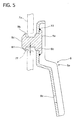
- FIG. 5 is an enlarged sectional side view of the bracket with the pin, taken along the line S5-S5 in FIG. 3;
- FIG. 6 is a perspective view showing the coupling structure in which the hood lock and the bracket are coupled with the radiator core support;
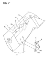
- FIG. 7 is a perspective view showing the radiator core support and the bracket before they are assembled with each other and the hood lock is coupled on the radiator core support;
- FIG. 8 is a perspective view showing the radiator core support and the bracket after they are assembled with each other and before the hood lock is coupled on the radiator core support;
- FIG. 9 is a perspective view showing the radiator core support coupled with the bracket and the hood lock in a state that the hood lock is temporally assembled with the radiator core support by the pin without bolts;
- FIG. 10 is an enlarged sectional side view of a bracket with a pin used in a coupling structure of a hood lock of a second embodiment according to the present invention; and
- FIG. 11 is an enlarged sectional side view of a bracket with a pin used in a coupling structure of a hood lock of a third embodiment according to the present invention.
Throughout the following detailed description, similar reference characters and numbers refer to similar elements in all figures of the drawings, and their descriptions are omitted for eliminating duplication.
Hereinafter, a first embodiment of the present invention will be described based on the drawings.
As shown in FIG. 1, a coupling structure of a hood lock of the first embodiment includes aradiator core support 1, abracket 8 fixed on theradiator core support 1, and ahood lock 7 coupled on theradiator core support 1 between theradiator core support 1 and thebracket 8.
Theradiator core support 1 is mounted on a front potion of a not-shown vehicle body. The core support I has an upper radiator-core support member 2, a lower radiator-core support member 3 arranged in parallel to and under the upper radiator-core support member 2, right and left side radiator-core support members core support members core support members Theses members hood lock stay 5 are integrally formed of plastic by using plastic injection molding.
Theradiator core support 1 has openings 10 at its both sides, respectively. In eachopening 10, a not-shown fan driven by an electric motor is disposed for cooling a radiator core and a condenser core mounted thereon.
The upper radiator-core support member 2 is formed like a letter U in section, opening backward when the radiator core support is mounted on the vehicle body, and provided with a pitted portion at its central position. The pitted portion forms a space O, opening forward, for receiving thehood lock 7 and is formed with right andleft bolt holes 6a for coupling thehood lock 7 on the upper radiator-core support member 2.
Thehood lock stay 5 is formed with right and left through-holes 5a for fastening thebracket 8 thereon at its portion connected with the upper radiator-core support member 2.
Referring to FIG. 2, there is shown thehood lock 7, which includes a hood-lockmain body 7a, alatch 7b for engaging with a not-shown striker of an engine hood to restrain it in a fully closed state at a fully closed position of the engine hood, asecondary latch 7c for restraining the engine hood in a semiclosed stat of the engine hood, a release lever 7d integrally formed with thesecondary latch 7c for manually releasing its lock, and a spring S for biasing thesecondary latch 7c toward the striker so that they can engage with each other. All parts of thehood lock 7 are made of metal.
Thehood lock 7 is provided with upper right and left through-holes 7e on its upper portion and a lower through-hole 7f on its central lower portion.
These upper and lower through-holes holes left bolt holes 6a of theradiator core support 1, respectively, when they are assembled with each other.
Referring to FIGS. 3 and 5, there is shown thebracket 8. Thebracket 8 has a bracketmain body 8a, which is formed with an attachment-hole 8b on its upper portion and right and left through-holes 8c on its lower portion. Positions of the right and left through-holes 8c are set to correspond to those of the right and left through-holes 5a of the hood lock stay 5, respectively, when they are fixed to theradiator core support 1.
On the upper portion, apin 9 is fixed by welding, which is inserted into the attachment-hole 8b and projecting backward from thebracket 8 in a horizontal direction when the radiator core support 1 with thebracket 8 is attached to the vehicle body. Thebracket 8 and thepin 9 are made of metal.
As shown in FIG. 4, thepin 9 has aseat 9a consisting of a seating portion larger in diameter than the attachment-hole 8a and an inserting portion substantially equal in diameter to the attachment-hole 8a and insertable therein, atop portion 9c smaller than in diameter than the attachment-hole 8a, and aengagement portion 9b smaller in diameter than thetop portion 9c and connecting thetop portion 9c and the inserting portion of theseat 9a. The seat portion of theseat 9a is welded at X1 onto thebracket 8 in a state where the inserting portion is inserted into the attachment-hole 8a of thebracket 8 as shown in FIG. 5.
Referring to FIG. 6, there is shown the coupling of the hood lock, in which thebracket 8 with thepin 9 is fixed to theradiator core support 1 by rivets R1 through the right and left through-holes 8c of thebracket 8 and the right and left through-holes 5c of the hood lock stay 5, respectively. In this state, thepin 9 extends from thebracket 8 toward the heatexchanger core support 1, forming a gap between thetop portion 9c of thepin 9 and theradiator core support 1.
Thehood lock 7 is coupled on the pitted portion of theradiator core support 1 by two bolts B1 inserted through washers W and the upper right and left through-holes 7e and screwed into the right andleft bolt holes radiator core support 1.
Thepin 9 of thebracket 8 is inserted into the lower through-hole 7f of thehood lock 7 when thehood lock 7 and thebracket 8 are coupled with theradiator core support 1 so that thepin 9 and an wall portion forming the lower through-hole 7f of thehood lock 7 can be engaged with each other to ensure sufficient stiffness in the vertical direction of thehood lock 7 when the engine hood is pulled upward. Note that thepin 9 and the wall portion may be set whether they are in contact with each other or in non-contact with each other when the engine hood is not pulled up. In addition, thepin 9 and the wall portion can engage with each other in a horizontal direction, but horizontal force applied to them is smaller than vertical force applied to them.
The coupling structure of the hood lock is assembled as follows.
First, theradiator core support 1, thehood lock 7, thebracket 8 and others, such as the rivets R1, the bolts B1 and the washers W are prepared.
Next, thebracket 8 is, as shown in FIG. 7, positioned so that the positions of the right and left through-holes 8c of thebracket 8 can correspond to those of the right and left through-holes 5a of the hood lock stay 5, respectively. The right and left rivets are inserted into the right through-holes holes bracket 8 to the radiator core support as shown in FIG. 8.
Next, thehood lock 7 is inserted diagonally into the pitted portion so that the upper right and left through-holes 7e of thehood lock 7 can correspond to the right andleft bolt holes 6a of theradiator core support 1, respectively. Thehood lock 7 is rotated and stood erect, as shown in FIG. 9, so that thepin 9 of thebracket 8 is inserted into the lower through-hole 7f of thehood lock 7 as shown in FIG. 5. In this state, although a vertical gap W1 is generated between a lower surface of theengaging portion 9b of thepin 9 and the wall portion forming the lower through-hole 7f of thehood lock 7, they can contact with each other when they move relative to each other in the vertical direction.
In this state, thepin 9 can temporally hold thehood lock 7, thereby preventing thehood lock 7 from being fallen from theradiator core support 1 during their delivery in a radiator core support assembly line.
Then, thehood lock 7 is fastened to theradiator core support 1 by the right and left bolts B1, which are inserted through the right and left washers W and the upper right and left through-holes 7e of thehood lock 7 and screwed into the right and leftbolt holes 6a of theradiator core support 1, respectively.
The two bolts B1 are temporally tightened before the vertical adjustment of thehood lock 7, which is performed allowing for a position relationship between thehood lock 7 and the engine hood after theradiator core support 1 is mounted on the vehicle body. After finishing the adjustment, the bolts B1 are fully tightened.
The coupling structure of thehood lock 7 of the first embodiment has the following advantages.
Thehood lock 7 is coupled at its upper portion on theradiator core support 1 by twobolts B 1 and by the wall portion at its lower side being engageable with thepin 9 of the bracket fixed to theradiator core support 1. This can provide sufficient fixing stiffness in the vertical direction, preventing thehood lock 7 to be torn off from theradiator core support 1, when the engine hood is pulled upward. In addition, coupling the lower portion of the hood lock on theradiator core support 1 does not need a bolting. This removes a bolting work in the small space around the lower portion of thehood lock 7, decreasing the manufacturing process and cost.
Next, a coupling structure of a hood lock of a second embodiment according to the present invention will be described with reference to the accompanying drawing.
A configuration of a bracket with a pin is set arbitrarily. The second embodiment is an example of its modification.
As shown in FIG. 10, in the coupling structure of the hood lock of the second embodiment, abracket 8 is provided at its top portion with apin 20, which has a circular cylinder portion and a seat. The circular cylinder portion is formed smaller in diameter than a lower through-hole of the hood lock and projected from thebracket 8 in a horizontal direction and The circular cylinder portion is formed like a key in section to have anotch 20a therein. The seat is formed larger in diameter than the lower through-hole of the hood lock and is welded on thebracket 8. The other parts are similar to those of the first embodiment.
This key-like shapedpin 20 can improve fasten performance between thepin 20 and a not-shown hood lock.
Next, a coupling structure of a hood lock of a third embodiment according to the present invention will be described with reference to the accompanying drawing.
As shown in FIG. 11, in the coupling structure of the hood lock of the second embodiment, abracket 8 and apin 30 are integrally formed by using press working. A part of an upper portion of thebracket 8 is partially cut off and folded backward and its top portion is folded downward to form thepin 30 in a key-like shape. The other parts are similar to those of the first embodiment.
Thisbracket 8 with thepin 30 can decrease its manufacturing process and cost.
While there have been particularly shown and described with reference to preferred embodiments thereof, it will be understood that various modifications may be made therein.
For example, theradiator core support 1 may be made of metal material and plastic instead of using only plastic.
Thebracket 8, thepin 9 and theradiator core support 1 may be integrally formed by using plastic injection molding or metal press forming.
Claims (7)
- A coupling structure of a hood lock (7) comprising:a radiator core support (1) having an upper radiator-core support member (2) provided with a right bolt hole (6a) and a left bolt hole (6a);a bracket (8) fixed to the radiator core support (1) and having a pin (9; 20; 30) projecting toward the radiator core support (1) from the bracket (8); anda hood lock (7) having an upper portion and a lower portion, the upper portion being formed with an upper right through-hole (7e) and an upper left through-hole (7e), the lower portion being inserted between the radiator core support (1) and the bracket (8) and formed with a lower through-hole (7f) surrounded by a wall portion thereof, whereinthe hood lock (7) is coupled on the radiator core support (1) so that the upper portion is fastened on the radiator core support (1) by two bolts (B1, B1) inserted through the upper right and left through-holes (7e, 7e) of the hood lock (7) and screwed into the right and left bolt holes (6a, 6a) of the radiator core support (1), respectively, and the lower portion is fixable to the radiator core support (1) through the bracket (8) by engagement of the pin (9; 20; 30) of the bracket (8) and the wall portion of the hood lock (7) when the pin (9) and the wall portion move relative to each other.
- The coupling structure of the hood lock (7) according to claim 1, wherein
the pin (9) is connected wit the bracket (8). - The coupling structure of the hood lock (1) according to claim 1 or claim 2, wherein
the pin (9) includes a seat (9a) larger in diameter than the lower through-hole (7f) of the hood lock (7), a top portion (9c) smaller in diameter than the lower through-hole (7f), and an engaging portion (9b) smaller in diameter than the top portion (9a) and engageable with the wall portion of the hood lock (7). - The coupling structure of the hood lock (1) according to claim 1 or claim 2, wherein
the pin (20) is notched to have a key-like shape. - The coupling structure of the hood lock (1) of claim 1, wherein
the pin (30) and the bracket (8) are integrally formed with each other. - The coupling structure of the hood lock (1) according to claim 5, wherein
the pin (30) is formed by partially cutting off the bracket (8) and folding a cutting-off portion of the bracket (8). - The coupling structure of the hood lock (1) according to any one of claims 1 to 6, wherein
the bracket (8) has a right through-hole (8c) and a left through-hole (8c) under the pin (9; 20; 30), the bracket (8) being fixed to the radiator core support (1) by two rivets (R1, R1) inserted through the right and left through-holes (8c, 8c), respectively.
Applications Claiming Priority (1)
| Application Number | Priority Date | Filing Date | Title |
|---|---|---|---|
| JP2005122860A JP2006298167A (en) | 2005-04-20 | 2005-04-20 | Hood lock fixing structure |
Publications (1)
| Publication Number | Publication Date |
|---|---|
| EP1715124A2 true EP1715124A2 (en) | 2006-10-25 |
Family
ID=36648634
Family Applications (1)
| Application Number | Title | Priority Date | Filing Date |
|---|---|---|---|
| EP20060112453 Withdrawn EP1715124A2 (en) | 2005-04-20 | 2006-04-11 | Coupling structure of hood lock |
Country Status (3)
| Country | Link |
|---|---|
| US (1) | US20060237999A1 (en) |
| EP (1) | EP1715124A2 (en) |
| JP (1) | JP2006298167A (en) |
Cited By (2)
| Publication number | Priority date | Publication date | Assignee | Title |
|---|---|---|---|---|
| US20140152028A1 (en) * | 2012-11-26 | 2014-06-05 | GM Global Technology Operations LLC | Lock cross member and hood lock for a motor vehicle |
| CN111379482A (en) * | 2018-12-27 | 2020-07-07 | 长城汽车股份有限公司 | Hood Locks and Vehicles |
Families Citing this family (6)
| Publication number | Priority date | Publication date | Assignee | Title |
|---|---|---|---|---|
| KR101273367B1 (en) * | 2007-02-07 | 2013-06-11 | 한라비스테온공조 주식회사 | Front end module for automobile |
| US8196978B2 (en) * | 2008-04-18 | 2012-06-12 | Hyundai Motor Company | Carrier and front end module system |
| DE102011116208B4 (en) * | 2011-10-14 | 2021-07-15 | Daimler Ag | Front-end module |
| KR101360567B1 (en) | 2012-12-24 | 2014-02-11 | 기아자동차주식회사 | Front end module for vehicle |
| DE102021100298A1 (en) * | 2021-01-11 | 2022-07-14 | Bayerische Motoren Werke Aktiengesellschaft | vehicle lock |
| US12459577B2 (en) * | 2022-10-13 | 2025-11-04 | Nissan North America, Inc. | Vehicle front end assembly |
Family Cites Families (6)
| Publication number | Priority date | Publication date | Assignee | Title |
|---|---|---|---|---|
| JP2565377Y2 (en) * | 1991-09-06 | 1998-03-18 | マツダ株式会社 | Car front body structure |
| FR2800030B1 (en) * | 1999-10-25 | 2002-01-11 | Plastic Omnium Cie | AUTOMOTIVE VEHICLE STRUCTURE PART, ESPECIALLY FRONT OF TECHNICAL FRONT |
| FR2813849B1 (en) * | 2000-09-13 | 2002-12-20 | Peguform France | VEHICLE ASSEMBLY COMPRISING A COOLING CASSETTE AND A SUPPORT FRAME |
| EP1213207B2 (en) * | 2000-12-07 | 2014-11-26 | Calsonic Kansei Corporation | Radiator core support structure for vehicle |
| JP4009153B2 (en) * | 2002-07-10 | 2007-11-14 | ダイキョーニシカワ株式会社 | Front end panel |
| JP4105001B2 (en) * | 2003-02-10 | 2008-06-18 | カルソニックカンセイ株式会社 | Hood lock stay connection structure |
-
2005
- 2005-04-20 JP JP2005122860A patent/JP2006298167A/en active Pending
-
2006
- 2006-04-11 EP EP20060112453 patent/EP1715124A2/en not_active Withdrawn
- 2006-04-19 US US11/406,406 patent/US20060237999A1/en not_active Abandoned
Cited By (2)
| Publication number | Priority date | Publication date | Assignee | Title |
|---|---|---|---|---|
| US20140152028A1 (en) * | 2012-11-26 | 2014-06-05 | GM Global Technology Operations LLC | Lock cross member and hood lock for a motor vehicle |
| CN111379482A (en) * | 2018-12-27 | 2020-07-07 | 长城汽车股份有限公司 | Hood Locks and Vehicles |
Also Published As
| Publication number | Publication date |
|---|---|
| JP2006298167A (en) | 2006-11-02 |
| US20060237999A1 (en) | 2006-10-26 |
Similar Documents
| Publication | Publication Date | Title |
|---|---|---|
| EP1422112B1 (en) | Fastener for curtain airbag | |
| EP1653092A1 (en) | Vehicle mirror device assembly | |
| JP2002031118A (en) | Elastic clip fasteners | |
| EP1957323A1 (en) | Fastener | |
| JP2006161890A (en) | Fastener and air bag mounting structure | |
| JP6278915B2 (en) | Load transmission member | |
| US20060237999A1 (en) | Coupling structure of hood lock | |
| US20170334373A1 (en) | Locking Retainer System For Automotive Assembly | |
| EP0667433A1 (en) | Automobile door striker assembly | |
| WO2010051400A1 (en) | Locked base trim clip | |
| CN114802083A (en) | Improved ergonomic fastening clips | |
| US12546347B2 (en) | Fastening clip assembly | |
| US7185451B2 (en) | License plate holding bracket and the holding structure thereof | |
| JP3985218B2 (en) | Assistant grip mounting structure | |
| JPH10329753A (en) | Vehicle front-end module structure | |
| CN109501691B (en) | Self-retaining angled fastening device for securing a component to a door panel in a vehicle | |
| JP4797085B2 (en) | Shock absorption structure in the engine room | |
| WO2016116159A1 (en) | Radiator support cover. | |
| JP3353646B2 (en) | Mounting structure of airbag device | |
| JP2003048494A (en) | Routing structure of door harness | |
| JP2947028B2 (en) | Airbag device | |
| JP4259702B2 (en) | Mounting structure for interior parts | |
| JP3173241B2 (en) | Trunk trim mounting structure | |
| JP7711121B2 (en) | Fastener and hinge structure having fastener | |
| JP2005161986A (en) | Vehicle front fender assembly structure |
Legal Events
| Date | Code | Title | Description |
|---|---|---|---|
| PUAI | Public reference made under article 153(3) epc to a published international application that has entered the european phase |
Free format text: ORIGINAL CODE: 0009012 |
|
| AK | Designated contracting states |
Kind code of ref document: A2 Designated state(s): AT BE BG CH CY CZ DE DK EE ES FI FR GB GR HU IE IS IT LI LT LU LV MC NL PL PT RO SE SI SK TR |
|
| AX | Request for extension of the european patent |
Extension state: AL BA HR MK YU |
|
| STAA | Information on the status of an ep patent application or granted ep patent |
Free format text: STATUS: THE APPLICATION IS DEEMED TO BE WITHDRAWN |
|
| 18D | Application deemed to be withdrawn |
Effective date: 20091103 |