EP1714750A1 - Robot hand comprising gripping claws - Google Patents
Robot hand comprising gripping claws Download PDFInfo
- Publication number
- EP1714750A1 EP1714750A1 EP06007907A EP06007907A EP1714750A1 EP 1714750 A1 EP1714750 A1 EP 1714750A1 EP 06007907 A EP06007907 A EP 06007907A EP 06007907 A EP06007907 A EP 06007907A EP 1714750 A1 EP1714750 A1 EP 1714750A1
- Authority
- EP
- European Patent Office
- Prior art keywords
- pair
- gripping claws
- moving elements
- robot hand
- center axis
- Prior art date
- Legal status (The legal status is an assumption and is not a legal conclusion. Google has not performed a legal analysis and makes no representation as to the accuracy of the status listed.)
- Granted
Links
- 210000000078 claw Anatomy 0.000 title claims abstract description 61
- 230000008878 coupling Effects 0.000 claims abstract description 3
- 238000010168 coupling process Methods 0.000 claims abstract description 3
- 238000005859 coupling reaction Methods 0.000 claims abstract description 3
- 238000006073 displacement reaction Methods 0.000 description 6
- 210000000707 wrist Anatomy 0.000 description 3
- 210000000245 forearm Anatomy 0.000 description 2
Images

Classifications
-
- B—PERFORMING OPERATIONS; TRANSPORTING
- B25—HAND TOOLS; PORTABLE POWER-DRIVEN TOOLS; MANIPULATORS
- B25J—MANIPULATORS; CHAMBERS PROVIDED WITH MANIPULATION DEVICES
- B25J15/00—Gripping heads and other end effectors
- B25J15/02—Gripping heads and other end effectors servo-actuated
- B25J15/0206—Gripping heads and other end effectors servo-actuated comprising articulated grippers
Definitions
- the present invention relates to a robot hand of an industrial robot and to a robot handling system provided with that robot hand.
- multiarticulated industrial robots are used to hold workpieces.
- a vertical multiarticulated robot 100 for holding a dish-shaped workpiece W stored in a basket 101 opened at its top end is illustrated.
- the robot 100 is provided with a plurality of arm parts coupled to each other by an articulating part 104 so as to be pivotable within a vertical plane, that is, an upper arm 102 and a forearm 106, and a robot hand 110 attached to the front end of the forearm 106 via a wrist 108.
- FIG. 5 which is the enlarged view of the part shown by B in FIG. 4, the robot hand 110 is able to pivot about a center axis O of the robot hand 110 by the wrist 108 (FIG. 4).
- the robot hand 110 is provided with a hand shaft 121, a drive system 120 having moving elements 122, 124 able to approach and move apart from each other in a direction perpendicular to the center axis O and attached to the hand shaft, gripping claws 112, 114 coupled to the moving elements 122, 124 of the drive system 120, and a joint 116 coupled to the centers of the gripping claws 112, 114 so as to be pivotable.
- the robot hand attached to the front of a robot arm of an industrial robot has various shapes so as to match with the shapes of different workpieces.
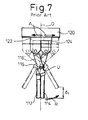
- FIG. 5 when holding a dish-shaped workpiece W having in cross-section a substantially circular inner circumference W 0 , the front ends of the gripping claws 112, 114 are made to move apart from each other to engage with the inner circumference W 0 of the workpiece W to thereby hold the workpiece W. Therefore, in the robot hand 110 according to the prior art, the moving elements 122, 124 of the drive system 120, as shown by the arrow A in FIG. 7, are operated to move apart from each other in opposite directions so that the front ends of the gripping claws 112, 114 pivot about the joint 116 as shown by the arrow R.
- the joint 116 moves along the center axis O to a position 116'.
- the gripping claws 112, 114 operate to rotate about the joint 116 as shown by the arrow R, so the front ends of the gripping claws 112, 114 move along the center axis O in the same direction as the joint 116.
- the displacement ⁇ 1 of the front ends of the gripping claws 112, 114 along the center axis O becomes large and the workpiece W cannot be accurately held.
- an object of the present invention is to solve the problem in the prior art and provide a robot hand reducing the amount of movement of the front ends of the gripping claws of the robot hand along the center axis of the robot hand when holding a workpiece.
- a robot hand attached to a front end of a robot arm, which includes a drive unit having a pair of moving elements provided so as to be linearly movable in a lateral direction with respect to a center axis of the robot hand, a pair of gripping claws each coupled with one of the pair of moving elements of the drive unit, and a joint positioned on the center axis and coupling the pair of gripping claws to each other so as to be pivotable, each of the pair of gripping claws having a base end coupled to one of the moving elements at one end so as to be pivotable and a front end for engaging with a workpiece, the base end of each of the pair of gripping claws being coupled by the joint to the base end of the other gripping claw at the other end thereof, the front ends of the pair of gripping claws being moving by moving the moving elements to make the base ends thereof pivot about the joint, the front ends of the pair of gripping claws extending from the base ends thereof so that
- the front ends of the gripping claws are preferably positioned at the same sides as the moving elements driving the gripping claws in relation to the center axis. Further, the pair of gripping claws are more preferably members bent into substantially V-shapes about the joint.
- the joint preferably includes a pin member extending perpendicularly with respect to both the center axis and the direction of movement of the moving elements.
- the workpiece has in cross-section a substantially circular inner circumference, while the robot hand engages with the inner circumference in the state with the front ends of the gripping claws moved apart from each other to hold the workpiece.
- a robot handling system which includes a multiarticulated robot arm comprised of a plurality of arm parts coupled to each other by articulating parts so as to be rotatable and the above-described robot hand attached to the front end of the robot arm.
- the front ends of the gripping claws move apart from or approach each other. Therefore, the movement of the joint along the center axis accompanying movement of the moving elements and the movement of the front ends of the gripping claws along the center axis become opposite in direction and the amount of displacement of the gripping claws becomes smaller.
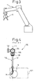
- the robot hand 10 is designed to be attached to a wrist provided at a front end of a robot arm 11 of for example the multiarticulated industrial robot of the prior art described with reference to FIGS. 4 and 5 or a hand shaft attached thereto so as to form a robot handling system.
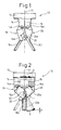
- the robot hand 10 is provided with a pair of gripping claws 18, 20 coupled to each other so as to be pivotable about a joint 22 and a pneumatic type drive system 12 for driving the pair of gripping claws 18, 20.
- the drive system 12 is provided with a pair of moving elements 14, 16 approaching and moving apart from each other in a lateral direction in relation to a center axis O of the robot hand 10 and a pneumatic cylinder (not shown) for driving the moving elements 14, 16.
- the joint 22 is positioned on the center axis O. In the present embodiment, it is comprised of a cylindrical pin member extending perpendicularly with respect to the center axis O and the direction of movement of the moving elements 14, 16.
- Each of the gripping claws 18, 20 has a body member 18a or 20a comprised of plate-shaped member forming a base end and a finger member 18b or 20b comprised of a rod-shaped member forming a front end.
- the body members 18a, 20a are coupled by pin member 14a, 16a extending in parallel with the joint 22 at the base ends thereof to the moving elements 14, 16 so as to be pivotable.
- the finger members 18b, 20b are attached to the body members 18a, 20a of the gripping claws so that their front ends are positioned at the same sides as the moving elements 14, 16 driving the gripping claws 18, 20 including the finger members 18b, 20b relative to the center axis. That is, the finger members 18b, 20b, as shown in FIG.
- FIG. 1 shows the angle ⁇ for only one gripping claw 18 among the gripping claws 18, 20, but the view is similar for the other gripping claw 20 as well.
- the robot hand 10 due to the action of the moving elements 14, 16 moving apart from each other, as shown by the solid line in FIG. 2, the front ends of the gripping claws 18, 20 approach each other.
- the robot hand 10 of the present embodiment like the robot hand 110 of the prior art, as shown in FIG. 5, the front ends of the gripping claws 18, 20 engage with the inner circumference W 0 of the workpiece W to thereby hold the workpiece. Therefore, in the robot hand 10, from the state of FIG. 2, the moving elements 14, 16 are operated to approach each other as shown by the arrow A to make the front ends of the gripping claws 18, 20 move apart from each other as shown by the arrow R.
- the gripping claws 18, 20, as described above operate to turn about the joint 22 as shown by the arrow R, so the front ends of the gripping claws 18, 20 move along the center axis O in a direction opposite to the movement direction of the joint 22.
- the displacement ⁇ of the front ends of the gripping claws 18, 20 along the center axis O becomes much smaller compared with the displacement ⁇ 1 of the gripping claws 112, 114 of the robot hand 110 of the prior art shown in FIG. 7. Therefore, when using the robot hand 10 to hold the workpiece W, even if the robot arm is not operated to compensate for displacement of the gripping claws 112, 114, the workpiece W can be sufficiently held by the robot hand 10.
- the displacement ⁇ of the front ends of the gripping claws along the center axis O is small, it becomes possible to easily estimate the positions of the gripping claws 18, 20 in the open state from the positions of the front ends of the gripping claws in the closed state. This has the advantage of facilitating teaching of the robot.
- the gripping claws 18, 20 move around the workpiece, even if the workpiece is tilted, the claws will not interfere with it other than at the locations of the front ends of the gripping claws. Therefore, there is no need to change the orientation of the hand in accordance with the change in orientation of the workpiece.
Landscapes
- Engineering & Computer Science (AREA)
- Robotics (AREA)
- Mechanical Engineering (AREA)
- Manipulator (AREA)
Abstract
Description
- The present invention relates to a robot hand of an industrial robot and to a robot handling system provided with that robot hand.
- At the present time, in the field of factory automation, multiarticulated industrial robots are used to hold workpieces. For example, in the prior art shown in FIG. 4, a vertical
multiarticulated robot 100 for holding a dish-shaped workpiece W stored in abasket 101 opened at its top end is illustrated. Therobot 100 is provided with a plurality of arm parts coupled to each other by anarticulating part 104 so as to be pivotable within a vertical plane, that is, anupper arm 102 and aforearm 106, and arobot hand 110 attached to the front end of theforearm 106 via awrist 108. Referring to FIG. 5 which is the enlarged view of the part shown by B in FIG. 4, therobot hand 110 is able to pivot about a center axis O of therobot hand 110 by the wrist 108 (FIG. 4). - Referring to FIGS. 5 and 6, the
robot hand 110 according to the prior art is provided with ahand shaft 121, adrive system 120 having movingelements claws elements drive system 120, and ajoint 116 coupled to the centers of thegripping claws - The robot hand attached to the front of a robot arm of an industrial robot has various shapes so as to match with the shapes of different workpieces. For example as shown in FIG. 5, when holding a dish-shaped workpiece W having in cross-section a substantially circular inner circumference W0, the front ends of the
gripping claws robot hand 110 according to the prior art, themoving elements drive system 120, as shown by the arrow A in FIG. 7, are operated to move apart from each other in opposite directions so that the front ends of thegripping claws joint 116 as shown by the arrow R. At this time, thejoint 116, as shown by the arrow U, moves along the center axis O to a position 116'. During this time, thegripping claws joint 116 as shown by the arrow R, so the front ends of thegripping claws joint 116. There is therefore the problem that the displacement δ1 of the front ends of thegripping claws - Accordingly, an object of the present invention is to solve the problem in the prior art and provide a robot hand reducing the amount of movement of the front ends of the gripping claws of the robot hand along the center axis of the robot hand when holding a workpiece.
- To achieve the above object, according to the present invention, there is provided a robot hand attached to a front end of a robot arm, which includes a drive unit having a pair of moving elements provided so as to be linearly movable in a lateral direction with respect to a center axis of the robot hand, a pair of gripping claws each coupled with one of the pair of moving elements of the drive unit, and a joint positioned on the center axis and coupling the pair of gripping claws to each other so as to be pivotable, each of the pair of gripping claws having a base end coupled to one of the moving elements at one end so as to be pivotable and a front end for engaging with a workpiece, the base end of each of the pair of gripping claws being coupled by the joint to the base end of the other gripping claw at the other end thereof, the front ends of the pair of gripping claws being moving by moving the moving elements to make the base ends thereof pivot about the joint, the front ends of the pair of gripping claws extending from the base ends thereof so that the front ends thereof move apart from each other when the pair of moving elements are made to approach each other in a lateral direction with respect to the center axis and so that the front ends thereof approach each other when the pair of moving elements are made to move apart from each other in a lateral direction with respect to the center axis.
- The front ends of the gripping claws are preferably positioned at the same sides as the moving elements driving the gripping claws in relation to the center axis. Further, the pair of gripping claws are more preferably members bent into substantially V-shapes about the joint.
- Further, the joint preferably includes a pin member extending perpendicularly with respect to both the center axis and the direction of movement of the moving elements.
- Further, the workpiece has in cross-section a substantially circular inner circumference, while the robot hand engages with the inner circumference in the state with the front ends of the gripping claws moved apart from each other to hold the workpiece.
- Further, according to the present invention, there is provided a robot handling system which includes a multiarticulated robot arm comprised of a plurality of arm parts coupled to each other by articulating parts so as to be rotatable and the above-described robot hand attached to the front end of the robot arm.
- According to the present invention, by operating the moving elements to linearly approach or move apart from each other, the front ends of the gripping claws move apart from or approach each other. Therefore, the movement of the joint along the center axis accompanying movement of the moving elements and the movement of the front ends of the gripping claws along the center axis become opposite in direction and the amount of displacement of the gripping claws becomes smaller.
- The above and other objects, features and advantages of the present invention will be described in more detail below based on the preferred embodiments of the present invention with reference to the accompanying drawings, wherein:
- FIG. 1 is a front view of a robot hand according to a preferred embodiment of the present invention;
- FIG. 2 is a view for explaining the operation of the robot hand of FIG. 1;
- FIG. 3 is a view of the overall configuration showing a robot arm with a robot hand attached thereto;
- FIG. 4 is a view showing a multiarticulated industrial robot holding a workpiece;
- FIG. 5 is an enlarged view of a part shown by B in FIG. 4;
- FIG. 6 is a front view of a robot hand according to the prior art; and
- FIG. 7 is a view for explaining the operation of the robot hand of FIG. 6.
- Preferred embodiments of the present invention will be described in detail below while referring to the attached figures.
- The
robot hand 10 according to the present embodiment, as shown in FIG. 3, is designed to be attached to a wrist provided at a front end of arobot arm 11 of for example the multiarticulated industrial robot of the prior art described with reference to FIGS. 4 and 5 or a hand shaft attached thereto so as to form a robot handling system. Referring to FIGS. 1 and 2, therobot hand 10 is provided with a pair of grippingclaws type drive system 12 for driving the pair of grippingclaws drive system 12 is provided with a pair of movingelements robot hand 10 and a pneumatic cylinder (not shown) for driving themoving elements joint 22 is positioned on the center axis O. In the present embodiment, it is comprised of a cylindrical pin member extending perpendicularly with respect to the center axis O and the direction of movement of themoving elements - Each of the gripping
claws body member finger member body members pin member joint 22 at the base ends thereof to the movingelements finger members body members elements gripping claws finger members finger members body members body members moving elements joint 22 and the center of thepin member joint 22 and the front end of thefinger member claw 18 among thegripping claws claw 20 as well. - The operation of the present embodiment will be described below.
- According to the present embodiment, in the
robot hand 10, due to the action of the movingelements gripping claws robot hand 10 of the present embodiment, like therobot hand 110 of the prior art, as shown in FIG. 5, the front ends of thegripping claws robot hand 10, from the state of FIG. 2, the movingelements gripping claws - At this time, the
joint 22, as shown by the arrow L, moves along the center axis O to the position shown by 22' toward the front end direction of therobot hand 10. During this time, thegripping claws joint 22 as shown by the arrow R, so the front ends of thegripping claws joint 22. The displacement δ of the front ends of thegripping claws gripping claws robot hand 110 of the prior art shown in FIG. 7. Therefore, when using therobot hand 10 to hold the workpiece W, even if the robot arm is not operated to compensate for displacement of thegripping claws robot hand 10. - Further, since the displacement δ of the front ends of the gripping claws along the center axis O is small, it becomes possible to easily estimate the positions of the
gripping claws gripping claws
Claims (4)
- A robot hand (10) attached to a front end of a robot arm, comprising:a drive unit (12) having a pair of moving elements (14, 16) provided so as to be linearly movable in a lateral direction with respect to a center axis (O) of said robot hand (10);a pair of gripping claws (18, 20) each coupled with one of the pair of moving elements (14, 16) of said drive unit (12); anda joint (22) positioned on said center axis (O) and coupling said pair of gripping claws (18, 20) to each other so as to be pivotable,each of said pair of gripping claws (18, 20) having a base end coupled to one of said moving elements (14, 16) at one end so as to be pivotable and a front end for engaging with a workpiece (W),the base end of each of said pair of gripping claws (18, 20) being coupled by said joint to the base end of the other gripping claw at the other end thereof,the front ends of said pair of gripping claws (18, 20) being moved by moving said moving elements (14, 16) to make said base ends thereof pivot about said joint (14, 16),the front ends of said pair of gripping claws (18, 20) extending from said base ends thereof so that the front ends thereof move apart from each other when said pair of moving elements (14, 16) are made to approach each other in a lateral direction with respect to said center axis (O) and so that the front ends thereof approach each other when said pair of moving elements (14, 16) are made to move apart from each other in a lateral direction with respect to said center axis (O).
- The robot hand according to claim 1, wherein the front ends of said pair of gripping claws (18, 20) are positioned at the same sides as the moving elements (14, 16) driving said gripping claws in relation to said center axis (O).
- The robot hand according to claim 2, wherein said pair of gripping claws (18, 20) are members bent into substantially V-shapes about said joint (22).
- A robot handling system comprising:a multiarticulated robot arm (11) comprised of a plurality of arm parts coupled to each other by articulating parts so as to be rotatable; anda robot hand (10) attached to the front end of said robot arm (11) according to any one of claims 1 to 3.
Applications Claiming Priority (1)
| Application Number | Priority Date | Filing Date | Title |
|---|---|---|---|
| JP2005120226A JP2006297514A (en) | 2005-04-18 | 2005-04-18 | Robot hand |
Publications (2)
| Publication Number | Publication Date |
|---|---|
| EP1714750A1 true EP1714750A1 (en) | 2006-10-25 |
| EP1714750B1 EP1714750B1 (en) | 2008-06-04 |
Family
ID=36602702
Family Applications (1)
| Application Number | Title | Priority Date | Filing Date |
|---|---|---|---|
| EP06007907A Ceased EP1714750B1 (en) | 2005-04-18 | 2006-04-13 | Robot hand comprising gripping claws |
Country Status (5)
| Country | Link |
|---|---|
| US (1) | US20060232086A1 (en) |
| EP (1) | EP1714750B1 (en) |
| JP (1) | JP2006297514A (en) |
| CN (1) | CN1853881A (en) |
| DE (1) | DE602006001375D1 (en) |
Cited By (2)
| Publication number | Priority date | Publication date | Assignee | Title |
|---|---|---|---|---|
| ITBS20080209A1 (en) * | 2008-11-20 | 2010-05-21 | Gimatic Spa | PNEUMATIC CONTROL DEVICE |
| EP3421192A1 (en) * | 2017-06-30 | 2019-01-02 | System 3R International AB | Gripping device, robot having such a gripping device, and wire electric discharge machining machine cell, having such a robot |
Families Citing this family (13)
| Publication number | Priority date | Publication date | Assignee | Title |
|---|---|---|---|---|
| CN102149520B (en) | 2008-09-10 | 2013-09-18 | 谐波传动系统有限公司 | Handling method of manipulator and plate-like objects |
| JP5895337B2 (en) | 2010-09-15 | 2016-03-30 | セイコーエプソン株式会社 | robot |
| JP5682810B2 (en) * | 2010-09-15 | 2015-03-11 | セイコーエプソン株式会社 | robot |
| JP5618198B2 (en) * | 2010-09-24 | 2014-11-05 | 株式会社安川電機 | Hand and robot |
| USD678377S1 (en) * | 2011-06-28 | 2013-03-19 | Kabushiki Kaisha Yaskawa Denki | Industrial robot hand |
| JP5266377B2 (en) * | 2011-12-19 | 2013-08-21 | ファナック株式会社 | Taking-out device having a function of correcting the posture of an article |
| JP6545671B2 (en) * | 2014-05-27 | 2019-07-17 | 川崎重工業株式会社 | End effector, industrial robot, and method of operating the same |
| DE102014210331A1 (en) * | 2014-06-02 | 2015-12-03 | Kuka Systems Gmbh | Jaw security with tongue and groove for MRK |
| JP6571583B2 (en) * | 2016-04-15 | 2019-09-04 | ファナック株式会社 | Robotic gripping device |
| JP6789728B2 (en) * | 2016-08-31 | 2020-11-25 | 川崎重工業株式会社 | Robot and its driving method |
| JP6473987B2 (en) * | 2017-01-10 | 2019-02-27 | Biデザイン合同会社 | Lift device and transport device provided with lift device |
| CN110193844A (en) * | 2019-07-05 | 2019-09-03 | 湖北天华智能装备股份有限公司 | Transfer robot quick-changing type grip manipulator |
| DE102021102128A1 (en) | 2021-01-29 | 2022-08-04 | SIM Automation GmbH | Grippers, handling robots and methods for handling a variety of components |
Citations (3)
| Publication number | Priority date | Publication date | Assignee | Title |
|---|---|---|---|---|
| JPS5313767A (en) * | 1976-07-20 | 1978-02-07 | Shin Meiwa Ind Co Ltd | Gripper for industrial robot |
| JPS6150882A (en) * | 1984-08-16 | 1986-03-13 | Mazda Motor Corp | Battery loading device in compound assembling line for automobile |
| JPH05237786A (en) * | 1992-02-28 | 1993-09-17 | Yoshimi Hoshino | Gripper |
Family Cites Families (7)
| Publication number | Priority date | Publication date | Assignee | Title |
|---|---|---|---|---|
| US2757037A (en) * | 1953-05-08 | 1956-07-31 | Berger Engineering Company | Log loading tongs |
| US4484775A (en) * | 1982-08-23 | 1984-11-27 | The United States Of America As Represented By The Secretary Of The Army | Adjustable smooth action linkage gripper mechanism |
| US4728137A (en) * | 1986-07-22 | 1988-03-01 | American Engineering And Trade, Inc. | Compound toggle robotic gripper |
| JPH058064Y2 (en) * | 1987-05-25 | 1993-03-01 | ||
| US4898416A (en) * | 1988-07-05 | 1990-02-06 | Hughes Aircraft Company | Pickup device |
| DE19525018C2 (en) * | 1995-06-28 | 1997-04-17 | Mannesmann Ag | Device for gripping and weight-dependent clamping of workpieces, rail guides or the like which are to be moved or held relative to a local position. |
| US6361095B1 (en) * | 2000-06-29 | 2002-03-26 | Delaware Capital Formation, Inc. | Adjustable stroke gripper assembly |
-
2005
- 2005-04-18 JP JP2005120226A patent/JP2006297514A/en active Pending
-
2006
- 2006-04-13 DE DE602006001375T patent/DE602006001375D1/en not_active Expired - Fee Related
- 2006-04-13 EP EP06007907A patent/EP1714750B1/en not_active Ceased
- 2006-04-17 US US11/279,965 patent/US20060232086A1/en not_active Abandoned
- 2006-04-18 CN CNA2006100758274A patent/CN1853881A/en active Pending
Patent Citations (3)
| Publication number | Priority date | Publication date | Assignee | Title |
|---|---|---|---|---|
| JPS5313767A (en) * | 1976-07-20 | 1978-02-07 | Shin Meiwa Ind Co Ltd | Gripper for industrial robot |
| JPS6150882A (en) * | 1984-08-16 | 1986-03-13 | Mazda Motor Corp | Battery loading device in compound assembling line for automobile |
| JPH05237786A (en) * | 1992-02-28 | 1993-09-17 | Yoshimi Hoshino | Gripper |
Non-Patent Citations (3)
| Title |
|---|
| PATENT ABSTRACTS OF JAPAN vol. 002, no. 054 (M - 016) 19 April 1978 (1978-04-19) * |
| PATENT ABSTRACTS OF JAPAN vol. 010, no. 211 (M - 501) 24 July 1986 (1986-07-24) * |
| PATENT ABSTRACTS OF JAPAN vol. 017, no. 694 (M - 1531) 17 December 1993 (1993-12-17) * |
Cited By (2)
| Publication number | Priority date | Publication date | Assignee | Title |
|---|---|---|---|---|
| ITBS20080209A1 (en) * | 2008-11-20 | 2010-05-21 | Gimatic Spa | PNEUMATIC CONTROL DEVICE |
| EP3421192A1 (en) * | 2017-06-30 | 2019-01-02 | System 3R International AB | Gripping device, robot having such a gripping device, and wire electric discharge machining machine cell, having such a robot |
Also Published As
| Publication number | Publication date |
|---|---|
| EP1714750B1 (en) | 2008-06-04 |
| JP2006297514A (en) | 2006-11-02 |
| CN1853881A (en) | 2006-11-01 |
| DE602006001375D1 (en) | 2008-07-17 |
| US20060232086A1 (en) | 2006-10-19 |
Similar Documents
| Publication | Publication Date | Title |
|---|---|---|
| EP1714750B1 (en) | Robot hand comprising gripping claws | |
| US8840097B2 (en) | Production system | |
| US10105853B1 (en) | Flexible robot end-effector for assembling door closure | |
| US20170151679A1 (en) | Gripping device having opened and closed gripping modes | |
| US20150100147A1 (en) | Robot system and method for manufacturing component | |
| WO2005051610A3 (en) | An industrial robot with controlled flexibility and simulated force for automated assembly | |
| US7421314B2 (en) | Method and device for controlling robot | |
| IT1203213B (en) | MANIPULATOR DEVICE, PARTICULARLY FOR INDUSTRIAL ROBOTS | |
| JP2010120140A (en) | Robot system | |
| WO2003037574A3 (en) | Robotic arm provided with a gripping head having a constant orientation | |
| JP6878027B2 (en) | Robot hand, robot hand control method, article manufacturing method using robot hand, robot device, control program and recording medium | |
| US20220134582A1 (en) | Robotic processing system | |
| CN115916484A (en) | Robot system and operating method of robot system | |
| JP2015085481A (en) | Robot, robot system, robot controller and gripping method | |
| WO2005009690A3 (en) | Cartesian coordinates type robot | |
| Canali et al. | High reconfigurable robotic gripper for flexible assembly | |
| JPH0123752Y2 (en) | ||
| US5692790A (en) | System for locating an end effector of a robot relative to a part | |
| CN210704906U (en) | Multifunctional end manipulator of industrial robot | |
| JP5157815B2 (en) | Robot apparatus and robot apparatus teaching method | |
| JP5365156B2 (en) | Robot equipment | |
| JP7802555B2 (en) | Grippers and robots | |
| US4708383A (en) | Manipulator gripper tool | |
| JPS62181892A (en) | Grip hand | |
| EP0062071A1 (en) | Through double hand |
Legal Events
| Date | Code | Title | Description |
|---|---|---|---|
| PUAI | Public reference made under article 153(3) epc to a published international application that has entered the european phase |
Free format text: ORIGINAL CODE: 0009012 |
|
| AK | Designated contracting states |
Kind code of ref document: A1 Designated state(s): AT BE BG CH CY CZ DE DK EE ES FI FR GB GR HU IE IS IT LI LT LU LV MC NL PL PT RO SE SI SK TR |
|
| AX | Request for extension of the european patent |
Extension state: AL BA HR MK YU |
|
| 17P | Request for examination filed |
Effective date: 20061019 |
|
| AKX | Designation fees paid |
Designated state(s): DE |
|
| GRAP | Despatch of communication of intention to grant a patent |
Free format text: ORIGINAL CODE: EPIDOSNIGR1 |
|
| GRAC | Information related to communication of intention to grant a patent modified |
Free format text: ORIGINAL CODE: EPIDOSCIGR1 |
|
| GRAS | Grant fee paid |
Free format text: ORIGINAL CODE: EPIDOSNIGR3 |
|
| GRAA | (expected) grant |
Free format text: ORIGINAL CODE: 0009210 |
|
| AK | Designated contracting states |
Kind code of ref document: B1 Designated state(s): DE |
|
| REF | Corresponds to: |
Ref document number: 602006001375 Country of ref document: DE Date of ref document: 20080717 Kind code of ref document: P |
|
| PLBE | No opposition filed within time limit |
Free format text: ORIGINAL CODE: 0009261 |
|
| STAA | Information on the status of an ep patent application or granted ep patent |
Free format text: STATUS: NO OPPOSITION FILED WITHIN TIME LIMIT |
|
| 26N | No opposition filed |
Effective date: 20090305 |
|
| PG25 | Lapsed in a contracting state [announced via postgrant information from national office to epo] |
Ref country code: DE Free format text: LAPSE BECAUSE OF NON-PAYMENT OF DUE FEES Effective date: 20091103 |