EP1713559B1 - Pneumatic filter - Google Patents
Pneumatic filter Download PDFInfo
- Publication number
- EP1713559B1 EP1713559B1 EP05760814A EP05760814A EP1713559B1 EP 1713559 B1 EP1713559 B1 EP 1713559B1 EP 05760814 A EP05760814 A EP 05760814A EP 05760814 A EP05760814 A EP 05760814A EP 1713559 B1 EP1713559 B1 EP 1713559B1
- Authority
- EP
- European Patent Office
- Prior art keywords
- filter
- main body
- air
- sides
- probe
- Prior art date
- Legal status (The legal status is an assumption and is not a legal conclusion. Google has not performed a legal analysis and makes no representation as to the accuracy of the status listed.)
- Expired - Lifetime
Links
- 239000002245 particle Substances 0.000 claims description 14
- 229910045601 alloy Inorganic materials 0.000 claims description 3
- 239000000956 alloy Substances 0.000 claims description 3
- 238000005219 brazing Methods 0.000 claims description 3
- 239000003822 epoxy resin Substances 0.000 claims description 3
- 229920000647 polyepoxide Polymers 0.000 claims description 3
- 239000000523 sample Substances 0.000 description 32
- 239000007858 starting material Substances 0.000 description 16
- 238000000034 method Methods 0.000 description 11
- 239000012530 fluid Substances 0.000 description 6
- 239000000463 material Substances 0.000 description 4
- 238000004891 communication Methods 0.000 description 3
- 238000004519 manufacturing process Methods 0.000 description 3
- 238000002485 combustion reaction Methods 0.000 description 2
- 238000010276 construction Methods 0.000 description 2
- 238000001914 filtration Methods 0.000 description 2
- 239000000446 fuel Substances 0.000 description 2
- 230000001105 regulatory effect Effects 0.000 description 2
- 239000000356 contaminant Substances 0.000 description 1
- 238000011109 contamination Methods 0.000 description 1
- 238000005260 corrosion Methods 0.000 description 1
- 230000007797 corrosion Effects 0.000 description 1
- 230000008878 coupling Effects 0.000 description 1
- 238000010168 coupling process Methods 0.000 description 1
- 238000005859 coupling reaction Methods 0.000 description 1
- 238000005520 cutting process Methods 0.000 description 1
- 230000003247 decreasing effect Effects 0.000 description 1
- 238000012423 maintenance Methods 0.000 description 1
- 238000012986 modification Methods 0.000 description 1
- 230000004048 modification Effects 0.000 description 1
- 239000011148 porous material Substances 0.000 description 1
- 239000012255 powdered metal Substances 0.000 description 1
- 238000007789 sealing Methods 0.000 description 1
- 238000007493 shaping process Methods 0.000 description 1
- 239000010935 stainless steel Substances 0.000 description 1
- 229910001220 stainless steel Inorganic materials 0.000 description 1
Images


Classifications
-
- B—PERFORMING OPERATIONS; TRANSPORTING
- B01—PHYSICAL OR CHEMICAL PROCESSES OR APPARATUS IN GENERAL
- B01D—SEPARATION
- B01D45/00—Separating dispersed particles from gases or vapours by gravity, inertia, or centrifugal forces
- B01D45/04—Separating dispersed particles from gases or vapours by gravity, inertia, or centrifugal forces by utilising inertia
- B01D45/08—Separating dispersed particles from gases or vapours by gravity, inertia, or centrifugal forces by utilising inertia by impingement against baffle separators
-
- Y—GENERAL TAGGING OF NEW TECHNOLOGICAL DEVELOPMENTS; GENERAL TAGGING OF CROSS-SECTIONAL TECHNOLOGIES SPANNING OVER SEVERAL SECTIONS OF THE IPC; TECHNICAL SUBJECTS COVERED BY FORMER USPC CROSS-REFERENCE ART COLLECTIONS [XRACs] AND DIGESTS
- Y10—TECHNICAL SUBJECTS COVERED BY FORMER USPC
- Y10S—TECHNICAL SUBJECTS COVERED BY FORMER USPC CROSS-REFERENCE ART COLLECTIONS [XRACs] AND DIGESTS
- Y10S55/00—Gas separation
- Y10S55/14—Inertia separator
Definitions
- the present invention relates to a filter, and more particularly, a pneumatic filter having less frequency of clogging.
- a gaseous flow separator is described in US-A-3 815 336 .
- Compressed gas such as air is often used for starting an aircraft gas turbine, or jet engine.
- Compressed air flows to the starter which causes rotation of the compressors and the turbines within the jet engine.
- the jet fuel can be ignited within the combustion area/combustor to start the engine. Without the compressor/turbine rotation provided by the starter, fuel combustion and air flow through the engine will not be sufficient to start the engine.
- the compressed air from the air turbine starter is controlled by a starter valve, such as an air regulating and shut-off butterfly valve, and the starter valve is, in turn, controlled by a control valve.
- control valve is coupled to a probe that is disposed within the same duct within which the starter valve resides.
- the probe is configured to divert a portion of air that flows through the duct toward the control valve so that the control valve may be pneumatically operated.
- the air that flows through the starter valve duct may contain various particles, dirt, or other contaminants.
- particles in the air may buildup or collect on the components, thereby possibly decreasing operability and increasing frequency of maintenance.
- filters have been used downstream of the probe or mounted within the probe.
- the most common method for filtering has been the use of porous filters, such as those consisting of wire mesh or sintered powdered metal, embedded within the probe.
- porous filters have limited life due to pore clogging and thus necessitate frequent removal and replacement of the probe.
- Other types of filters have included down-stream facing filters. Although these types of filters do not need frequent replacement, they are not highly effective filters.
- the filter operates with or is an integral part of the probe.
- the improved filter be low in cost to manufacture and does not need frequent replacement.
- the present invention provides a filter configured to be disposed within an air passage, for providing filtered air to a pneumatically controlled component.
- the filter comprises a main body having first and second ends and a passageway extending therebetween, a leading edge, a trailing edge, and first and second sides.
- the first and second sides converge at least proximate the trailing edge and are separated from one another by a longitudinal slit that extends along a section thereof.
- the leading edge is configured to divide a main airflow containing particles into first and second airflow portions.
- the first airflow portion contains particles and is directed through the air passage and the second airflow portion is substantially particle-free and directed through the longitudinal slit into the main body passage.
- an air turbine starter has a duct, a valve, an actuator, a rate control servo and a filter.
- the valve is disposed within the duct, the actuator is coupled to the valve, and the rate control servo coupled to the actuator.
- the filter is disposed within the duct and is in fluid communication with the rate control servo.
- the filter comprises a main body having first and second ends and a passageway extending therebetween, a leading edge, a trailing edge, and first and second sides, the first and second sides converging at least proximate the trailing edge and are separated from one another by a longitudinal slit that extends along a section thereof.
- the leading edge is configured to divide a main airflow containing particles into first and second airflow portions, where the first airflow portion containing particles and being directed through the air passage and the second airflow portion being substantially particle-free and directed through the longitudinal slit into the main body passage.
- a method for constructing the filter comprises shaping a tube to include a leading edge, a trailing edge, first and second ends and a passage that extends therebetween, cutting a longitudinal slit into the tube trailing edge, and sealing the tube first end.
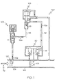
- FIG. 1 is a schematic of an exemplary starter control valve
- FIG. 2 is a close up view of the portion of the starter control valve within which an exemplary filter is disposed in FIG. 2 ;
- FIG. 3 is perspective view of the exemplary filter that can be used in the starter control valve of FIG. 1 ;
- FIG. 3A is a cross section view of the portion of exemplary filter of FIG. 4 along the lines 3A-3A showing airflow path;
- FIG. 3B is a cross section view similar to the view of FIG. 3A of a portion of another exemplary filter
- FIG. 4 is a flowchart of an exemplary method for the construction of the exemplary filter.
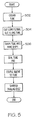
- FIG. 5 is a flowchart of another exemplary method for the construction of the exemplary filter.
- the present invention is not limited to use in conjunction with a specific type of valve.
- the present invention is, for convenience of explanation, depicted and described as being implemented in a butterfly valve shaft, it should be appreciated that it can be implemented in numerous other valve shafts, such as a fluid control valve, and various other machines in which filtered air is needed for pneumatic operation.
- the starter control valve 100 is pneumatically operated and generally includes a butterfly valve 102, a solenoid control valve 106, rate control servo 108, and actuator 110.
- the butterfly valve 102 is disposed within a duct 104 and is configured to open and close the duct 104 to control the flow of the pressurized air 112 to the air turbine starter (not shown).
- the duct 104 may be in fluid communication with any one of various sources of pressurized or compressed air, such as, for instance, an auxiliary power unit, bleed air from the compressor stage of another operating gas turbine engine, or a gas turbine ground power cart.
- a portion of the air 112a in the duct 104 is directed to the solenoid control valve 106 and rate control servo 108 to ultimately operate the actuator 110.
- the solenoid control valve 106 operates a valve mechanism 114 that is coupled thereto, such that when the solenoid control valve 106 is energized, it opens the valve mechanism 114, and when it is de-energized, the valve mechanism 114 is closed.
- the solenoid control valve 106 is further coupled to the rate control servo 108.
- the rate control servo 108 also has a valve mechanism 118 to control air flow, specifically, by regulating the rate at which the air flows through the air passages 116 and to the pneumatically-operated actuator 110.
- the airflow 112a serves as the pressure source for the operation of the actuator 110.
- the actuator 110 preferably includes a piston 118 that is in communication with the airflow 112a and responds to the pressure to thereby supply torque upon the butterfly valve 102 in a desired direction and at a controlled rate.
- the portion of airflow 112a is directed out of the duct 104 via a probe 120, which also serves as a filter.
- the filter or probe 120 at least partially extends into the duct 104 and is preferably mounted to the sidewall 122 thereof.
- the probe 120 includes a main body 123 that has first and second ends 126, 128 and a passage 130 extending between the first and second ends 126, 128.
- the probe first end 126 is preferably plugged, or otherwise sealed to prevent air or fluid from entering the first end 126.
- a sleeve 132 is coupled to the probe second end 128.
- the probe main body 123 includes at least two sections, a wing-shaped section 134 and a cylindrical section 136.
- the wing-shaped section 134 has a leading edge 13 8 and two sides 140, 142 that converge toward one another, at an angle 148, to form a trailing edge 144.
- the leading edge 138 is configured to cause particles 146 that may be present in the main airflow 112 to follow a path along the sides 140, 142 of the main body 123 and to continue along the same trajectory once the particles leave the sides 140, 142, as shown in FIG. 4A Once a particle 146 travels the path along one of the sides 140, 142, it builds up sufficient inertia to continue past the trailing edge 144.
- leading edge 138 is curved and smooth, however, as will be appreciated, the leading edge 138 can also beveled (shown in FIG. 3B ), so long as the included bevel angle is between approximately 10 and 20 degrees and most preferably about 13 degrees.
- an angle 148 is formed between the two sides 140, 142 of the main body 123. This angle 148, among other things, aids in keeping the particles 146 moving along a particular trajectory.
- the angle 148 that exists between the two sides 140, 142 is relatively small. In the preferred embodiment, the angle 148 between the two sides 140, 142 is between approximately 10 and 20 degrees, and most preferably about 13 degrees.
- the two sides 140, 142 are also spaced apart from one another by a longitudinal slit or small gap 150.
- the gap 150 is configured to be small enough so that the momentum of the particles 146 traveling along the sides 140, 142 causes them to continue along a particular trajectory so that they cannot round the corners of the sides 140, 142 to enter the tube passage 130.
- the gap 150 is preferably between 0.127 to 0.254 mm (.005-.010 inches).
- the gap 150 preferably extends along the majority of the trailing edge 144 of the wing-shaped section 134. However, as will be appreciated by those skilled in the art, the gap 150 may extend for any length along the trailing edge 144 such that a sufficient amount of particle-free air from the airflow 112 can enter into the passage 130.
- FIG. 3A A cross-section of the wing-shaped section 134 of the probe main body 123 depicted in FIG. 3 , taken along line 3A-3A is provided in FIG. 3A .
- the tip portions 145, 147 of each of the sides 140, 142 are configured so as to provide a tight bend around which a portion of the air from the airflow 106 travels.
- the tip portions 145, 147 are preferably razor-sharp to help in diverting substantially particle-free air into the probe passage 130.
- the edges of the two sides 140, 142 are preferably tapered.
- the end of the probe first end 126 is preferably plugged so that minimal amounts of air can leak out of the first end 126.
- the probe first end 126 may be plugged with an epoxy resin, bent, brazed, or otherwise closed.
- the second end 128 of the probe 120 has a sleeve 132 that is coupled thereto.
- the sleeve 132 is configured to tightly fit into a recess 152 of the duct sidewall 122 so as to prevent fluid leakage from the duct 104 into the recess 152.
- the sleeve 132 can be an appropriately shaped nut or any other type of mounting surface.
- the sleeve 132 also has a flow passage 154 that extends therethrough to allow the air 112a to fluidly communicate between the probe passage 130 and the air passage 116 of the control valve 100.
- the probe second end 128 is located on the cylindrical section 136, however, as may be appreciated, the cylindrical section 136 can be omitted altogether.
- the wing-shaped section 134 could extend the entire length of the probe 120, thus, the probe second end 128 would be located on the winged-section 134, and the sleeve 132 and associated flow passage 154 (shown in FIG. 2 ) would be appropriately shaped for coupling thereto.
- the probe 120 can be constructed of any one of numerous types of materials that is sufficiently stiff, corrosion-resistant, and provide for cost-effective manufacture. Moreover, sleeve 132 can be constructed of a different material than the rest of the probe 120. Most preferably, the probe 120 is constructed of stainless steel. Although the probe 120 can be constructed in any numerous ways, a preferred method of constructing the probe 120 will now be discussed
- the first step of the preferred method for constructing the probe 120 is to obtain an appropriately dimensioned tube (400).
- the size and diameter of the tube depends on the relative size of the duct in which the resulting probe will be disposed.
- the original tube is cylindrically- shaped. In another embodiment, the original tube is square-shaped. Once the tube is obtained, it is cut into a desired length.
- a portion of the tube is shaped into a wing (402), while another portion maintains its original shape.
- the entire length of the tube is shaped into a wing.
- a wing-shaped mold preferably having an angle of between 10-20 degrees, is inserted into the tube and the tube is crimped until it takes roughly the same shape as the mold.
- a slit is cut along the trailing edge of the wing-shaped tube resulting in a gap (404).
- the tube is placed into a holder and a wire electro-discharge machine is used to make the cut so that the desired portion to be cut is essentially eroded or corroded away and into the preferred shape.
- the gap is preferably between 0.127 to 0.254 mm (.005-.010 inches) in width.
- the wing-shape of the tube is refined.
- the tube is placed into a two-piece fixture, wherein each piece has one half of a cast of the wing-shaped mold used above. The fixture is then pressed together so that the tube takes the shape of the cast.
- one end of the tube is sealed (406).
- the end to be sealed is preferably plugged with epoxy resin or any other type of plugging material.
- the end to be sealed can be folded over, or a brazing alloy can be used to braze the end closed.
- a sleeve or any other type of mounting surface that is appropriately configured to fit into the recess in the valve sidewall and mounted on to the tube end is coupled thereto (408).
- the sleeve is fit on to the tube end and then a brazing alloy is used to fix the two together.
- the tip of the trailing edge of the wing-shaped tube is honed so that the trailing edge is razor-sharp (410).
- a longitudinal cut is made along at least a portion of the length of the tube (504).
- the tube can be placed into a holder and a wire electro-discharge machine can be used to make the cut so that the desired portion to be cut is essentially eroded or corroded away and into the preferred shape.
- the gap is preferably between 0.127 to 0.254 mm (.005-.010 inches) in width.
- a portion of the tube is shaped into a wing (506) such that the longitudinal cut is on the trailing edge of the wing-shape, while another portion maintains its original shape, or alternatively, the entire length of the tube is shaped into a wing.
- the remaining steps of this alternative method are similar to the method described in FIG. 4 .
- the filter meets the above-mentioned needs and is cost efficient to manufacture and easy to maintain. Moreover, the filter does not need frequent replacement.
Landscapes
- Chemical & Material Sciences (AREA)
- Chemical Kinetics & Catalysis (AREA)
- Filtering Materials (AREA)
- Filtering Of Dispersed Particles In Gases (AREA)
Description
- The present invention relates to a filter, and more particularly, a pneumatic filter having less frequency of clogging. A gaseous flow separator is described in
US-A-3 815 336 . - Compressed gas such as air is often used for starting an aircraft gas turbine, or jet engine. Compressed air flows to the starter which causes rotation of the compressors and the turbines within the jet engine. When sufficient air flows through the jet engine (reflected by turbine speed or otherwise), the jet fuel can be ignited within the combustion area/combustor to start the engine. Without the compressor/turbine rotation provided by the starter, fuel combustion and air flow through the engine will not be sufficient to start the engine. The compressed air from the air turbine starter is controlled by a starter valve, such as an air regulating and shut-off butterfly valve, and the starter valve is, in turn, controlled by a control valve.
- Typically, the control valve is coupled to a probe that is disposed within the same duct within which the starter valve resides. The probe is configured to divert a portion of air that flows through the duct toward the control valve so that the control valve may be pneumatically operated.
- At times, the air that flows through the starter valve duct may contain various particles, dirt, or other contaminants. When the air is directed to various parts of the control valve, such as for example, the orifices, valve mechanism, or springs, particles in the air may buildup or collect on the components, thereby possibly decreasing operability and increasing frequency of maintenance. To prevent or minimize particle contamination, filters have been used downstream of the probe or mounted within the probe. The most common method for filtering has been the use of porous filters, such as those consisting of wire mesh or sintered powdered metal, embedded within the probe. However, porous filters have limited life due to pore clogging and thus necessitate frequent removal and replacement of the probe. Other types of filters have included down-stream facing filters. Although these types of filters do not need frequent replacement, they are not highly effective filters.
- Accordingly, there exists a need for a filter with improved filtering capabilities. Preferably, the filter operates with or is an integral part of the probe. Additionally, it is desirable that the improved filter be low in cost to manufacture and does not need frequent replacement. Furthermore, other desirable features and characteristics of the present invention will become apparent from the subsequent detailed description of the invention and the appended claims, taken in conjunction with the accompanying drawings and this background of the invention.
- The present invention provides a filter configured to be disposed within an air passage, for providing filtered air to a pneumatically controlled component. In one embodiment, the filter comprises a main body having first and second ends and a passageway extending therebetween, a leading edge, a trailing edge, and first and second sides. The first and second sides converge at least proximate the trailing edge and are separated from one another by a longitudinal slit that extends along a section thereof. The leading edge is configured to divide a main airflow containing particles into first and second airflow portions. The first airflow portion contains particles and is directed through the air passage and the second airflow portion is substantially particle-free and directed through the longitudinal slit into the main body passage.
- In another embodiment, and by way of example only, an air turbine starter is provided. The air turbine starter has a duct, a valve, an actuator, a rate control servo and a filter. The valve is disposed within the duct, the actuator is coupled to the valve, and the rate control servo coupled to the actuator. Additionally, the filter is disposed within the duct and is in fluid communication with the rate control servo. The filter comprises a main body having first and second ends and a passageway extending therebetween, a leading edge, a trailing edge, and first and second sides, the first and second sides converging at least proximate the trailing edge and are separated from one another by a longitudinal slit that extends along a section thereof. The leading edge is configured to divide a main airflow containing particles into first and second airflow portions, where the first airflow portion containing particles and being directed through the air passage and the second airflow portion being substantially particle-free and directed through the longitudinal slit into the main body passage.
- In yet another embodiment, a method for constructing the filter is provided. The method comprises shaping a tube to include a leading edge, a trailing edge, first and second ends and a passage that extends therebetween, cutting a longitudinal slit into the tube trailing edge, and sealing the tube first end.
- Other independent features and advantages of the preferred air turbine starter will become apparent from the following detailed description, taken in conjunction with the accompanying drawings which illustrate, by way of example, the principles of the invention.
-
FIG. 1 is a schematic of an exemplary starter control valve; -
FIG. 2 is a close up view of the portion of the starter control valve within which an exemplary filter is disposed inFIG. 2 ; -
FIG. 3 is perspective view of the exemplary filter that can be used in the starter control valve ofFIG. 1 ; -
FIG. 3A is a cross section view of the portion of exemplary filter ofFIG. 4 along thelines 3A-3A showing airflow path; -
FIG. 3B is a cross section view similar to the view ofFIG. 3A of a portion of another exemplary filter; -
FIG. 4 is a flowchart of an exemplary method for the construction of the exemplary filter; and -
FIG. 5 is a flowchart of another exemplary method for the construction of the exemplary filter. - Before proceeding with the detailed description, it should be appreciated that the present invention is not limited to use in conjunction with a specific type of valve. Thus, although the present invention is, for convenience of explanation, depicted and described as being implemented in a butterfly valve shaft, it should be appreciated that it can be implemented in numerous other valve shafts, such as a fluid control valve, and various other machines in which filtered air is needed for pneumatic operation.
- Turning now to
FIG. 1 , an exemplary fluid control valve, orstarter control valve 100 is shown. Thestarter control valve 100 is pneumatically operated and generally includes abutterfly valve 102, asolenoid control valve 106,rate control servo 108, andactuator 110. Thebutterfly valve 102 is disposed within aduct 104 and is configured to open and close theduct 104 to control the flow of the pressurizedair 112 to the air turbine starter (not shown). Theduct 104 may be in fluid communication with any one of various sources of pressurized or compressed air, such as, for instance, an auxiliary power unit, bleed air from the compressor stage of another operating gas turbine engine, or a gas turbine ground power cart. - A portion of the
air 112a in theduct 104 is directed to thesolenoid control valve 106 andrate control servo 108 to ultimately operate theactuator 110. To this end, thesolenoid control valve 106 operates avalve mechanism 114 that is coupled thereto, such that when thesolenoid control valve 106 is energized, it opens thevalve mechanism 114, and when it is de-energized, thevalve mechanism 114 is closed. Thesolenoid control valve 106 is further coupled to therate control servo 108. Thus, when the solenoid control valve is energized, theair 112a is allowed to pass through the controlvalve air passages 116 to therate control servo 108. Therate control servo 108 also has avalve mechanism 118 to control air flow, specifically, by regulating the rate at which the air flows through theair passages 116 and to the pneumatically-operatedactuator 110. - The
airflow 112a serves as the pressure source for the operation of theactuator 110. Theactuator 110 preferably includes apiston 118 that is in communication with theairflow 112a and responds to the pressure to thereby supply torque upon thebutterfly valve 102 in a desired direction and at a controlled rate. - The portion of
airflow 112a is directed out of theduct 104 via aprobe 120, which also serves as a filter. With reference toFIGS. 1 and2 , the filter orprobe 120 at least partially extends into theduct 104 and is preferably mounted to thesidewall 122 thereof. - Referring to
FIGS. 2 and3 , theprobe 120 includes amain body 123 that has first andsecond ends passage 130 extending between the first andsecond ends first end 126 is preferably plugged, or otherwise sealed to prevent air or fluid from entering thefirst end 126. Asleeve 132 is coupled to the probesecond end 128. Each of these parts will now be discussed. - The probe
main body 123 includes at least two sections, a wing-shapedsection 134 and acylindrical section 136. The wing-shapedsection 134 has a leading edge 13 8 and twosides angle 148, to form a trailingedge 144. Theleading edge 138 is configured to causeparticles 146 that may be present in themain airflow 112 to follow a path along thesides main body 123 and to continue along the same trajectory once the particles leave thesides FIG. 4A Once aparticle 146 travels the path along one of thesides edge 144. Thus, it is most preferable that theleading edge 138 is curved and smooth, however, as will be appreciated, theleading edge 138 can also be beveled (shown inFIG. 3B ), so long as the included bevel angle is between approximately 10 and 20 degrees and most preferably about 13 degrees. - As was noted above, an
angle 148 is formed between the twosides main body 123. Thisangle 148, among other things, aids in keeping theparticles 146 moving along a particular trajectory. Preferably, theangle 148 that exists between the twosides angle 148 between the twosides - The two
sides small gap 150. Thegap 150 is configured to be small enough so that the momentum of theparticles 146 traveling along thesides sides tube passage 130. To this end, thegap 150 is preferably between 0.127 to 0.254 mm (.005-.010 inches). Thegap 150 preferably extends along the majority of the trailingedge 144 of the wing-shapedsection 134. However, as will be appreciated by those skilled in the art, thegap 150 may extend for any length along the trailingedge 144 such that a sufficient amount of particle-free air from theairflow 112 can enter into thepassage 130. - A cross-section of the wing-shaped
section 134 of the probemain body 123 depicted inFIG. 3 , taken alongline 3A-3A is provided inFIG. 3A . Thetip portions sides airflow 106 travels. Thus, thetip portions probe passage 130. Moreover, the edges of the twosides - As previously mentioned, the end of the probe
first end 126 is preferably plugged so that minimal amounts of air can leak out of thefirst end 126. To this end, the probefirst end 126 may be plugged with an epoxy resin, bent, brazed, or otherwise closed. Thesecond end 128 of theprobe 120 has asleeve 132 that is coupled thereto. As can be more clearly seen inFIG. 2 , thesleeve 132 is configured to tightly fit into arecess 152 of theduct sidewall 122 so as to prevent fluid leakage from theduct 104 into therecess 152. Thus, thesleeve 132 can be an appropriately shaped nut or any other type of mounting surface. Thesleeve 132 also has aflow passage 154 that extends therethrough to allow theair 112a to fluidly communicate between theprobe passage 130 and theair passage 116 of thecontrol valve 100. - In the depicted embodiment, the probe
second end 128 is located on thecylindrical section 136, however, as may be appreciated, thecylindrical section 136 can be omitted altogether. In such case, the wing-shapedsection 134 could extend the entire length of theprobe 120, thus, the probesecond end 128 would be located on the winged-section 134, and thesleeve 132 and associated flow passage 154 (shown inFIG. 2 ) would be appropriately shaped for coupling thereto. - The
probe 120 can be constructed of any one of numerous types of materials that is sufficiently stiff, corrosion-resistant, and provide for cost-effective manufacture. Moreover,sleeve 132 can be constructed of a different material than the rest of theprobe 120. Most preferably, theprobe 120 is constructed of stainless steel. Although theprobe 120 can be constructed in any numerous ways, a preferred method of constructing theprobe 120 will now be discussed - Turning to the flowchart provided in
FIG. 4 , each step of the method to be discussed is referenced hereafter in parentheses. The first step of the preferred method for constructing theprobe 120 is to obtain an appropriately dimensioned tube (400). The size and diameter of the tube depends on the relative size of the duct in which the resulting probe will be disposed. In a preferred embodiment, the original tube is cylindrically- shaped. In another embodiment, the original tube is square-shaped. Once the tube is obtained, it is cut into a desired length. - Next, a portion of the tube is shaped into a wing (402), while another portion maintains its original shape. Alternatively, the entire length of the tube is shaped into a wing. To this end, a wing-shaped mold, preferably having an angle of between 10-20 degrees, is inserted into the tube and the tube is crimped until it takes roughly the same shape as the mold. Next a slit is cut along the trailing edge of the wing-shaped tube resulting in a gap (404). Preferably, the tube is placed into a holder and a wire electro-discharge machine is used to make the cut so that the desired portion to be cut is essentially eroded or corroded away and into the preferred shape. The gap is preferably between 0.127 to 0.254 mm (.005-.010 inches) in width. Optionally, after the cut is made, the wing-shape of the tube is refined. In such case, preferably, the tube is placed into a two-piece fixture, wherein each piece has one half of a cast of the wing-shaped mold used above. The fixture is then pressed together so that the tube takes the shape of the cast.
- Then, one end of the tube is sealed (406). The end to be sealed is preferably plugged with epoxy resin or any other type of plugging material. Alternatively, the end to be sealed can be folded over, or a brazing alloy can be used to braze the end closed. At another end of the tube, a sleeve or any other type of mounting surface that is appropriately configured to fit into the recess in the valve sidewall and mounted on to the tube end is coupled thereto (408). Preferably, the sleeve is fit on to the tube end and then a brazing alloy is used to fix the two together. Optionally, the tip of the trailing edge of the wing-shaped tube is honed so that the trailing edge is razor-sharp (410). Once the
probe 120 is constructed, it is ready to be mounted to the duct sidewall and positioned so that when air flows through the duct, it first contacts the probe leading edge. - In an alternative method, shown in
FIG. 5 , after the tube is obtained (502), a longitudinal cut is made along at least a portion of the length of the tube (504). The tube can be placed into a holder and a wire electro-discharge machine can be used to make the cut so that the desired portion to be cut is essentially eroded or corroded away and into the preferred shape. The gap is preferably between 0.127 to 0.254 mm (.005-.010 inches) in width. Then, after the cut is made, a portion of the tube is shaped into a wing (506) such that the longitudinal cut is on the trailing edge of the wing-shape, while another portion maintains its original shape, or alternatively, the entire length of the tube is shaped into a wing. The remaining steps of this alternative method are similar to the method described inFIG. 4 . - Thus, a filter having the capability of serving as a probe has been provided. The filter meets the above-mentioned needs and is cost efficient to manufacture and easy to maintain. Moreover, the filter does not need frequent replacement.
- While the invention has been described with reference to a preferred embodiment, it will be understood by those skilled in the art that various changes may be made and equivalents may be substituted for elements thereof without departing from the scope of the invention. In addition, many modifications may be made to adapt to a particular situation or material to the teachings of the invention without departing from the scope thereof. Therefore, it is intended that the invention not be limited to the particular embodiment disclosed as the best mode contemplated for carrying out this invention, but that the invention will include all embodiments falling within the scope of the appended claims.
Claims (10)
- A filter configured to be disposed within an air passage, for providing filtered air to a pneumatically controlled component, comprising:a main body having first and second ends and a passageway extending therebetween, a leading edge, a trailing edge, and first and second sides, the first and second sides converging at least proximate the trailing edge and separated from one another by a longitudinal slit that extends along a section thereof,wherein the leading edge is configured to divide a main airflow containing particles into first and second airflow portions, the first airflow portion containing particles and being directed through the air passage and the second airflow portion being substantially particle-free and directed through the longitudinal slit into the main body passage.
- The filter of claim 1, further comprising:a sleeve coupled to the main body first end.
- The filter of claim 2, wherein the main body second end includes a seal.
- The filter of claim 3, wherein the seal is an epoxy resin.
- The filter of claim 3, wherein the seal is a brazing alloy brazed to the second end.
- The filter of claim 1, wherein the leading edge has a curved shape.
- The filter of claim 1, wherein the longitudinal slit extends the length of the main body.
- The filter of claim 1, wherein the width of the longitudinal slit is between 0.127 to 0.254 mm (.005-.010 inches).
- The filter of claim 1, wherein first and second sides have an angle between them of between 10-20 degrees.
- The filter of claim 1, wherein the first and second sides have an angle between them of about 13 degrees.
Applications Claiming Priority (2)
| Application Number | Priority Date | Filing Date | Title |
|---|---|---|---|
| US10/779,445 US7153346B2 (en) | 2004-02-12 | 2004-02-12 | Pneumatic filter and method of making |
| PCT/US2005/004382 WO2005089903A2 (en) | 2004-02-12 | 2005-02-11 | Pneumatic filter |
Publications (2)
| Publication Number | Publication Date |
|---|---|
| EP1713559A2 EP1713559A2 (en) | 2006-10-25 |
| EP1713559B1 true EP1713559B1 (en) | 2009-03-18 |
Family
ID=34972583
Family Applications (1)
| Application Number | Title | Priority Date | Filing Date |
|---|---|---|---|
| EP05760814A Expired - Lifetime EP1713559B1 (en) | 2004-02-12 | 2005-02-11 | Pneumatic filter |
Country Status (4)
| Country | Link |
|---|---|
| US (1) | US7153346B2 (en) |
| EP (1) | EP1713559B1 (en) |
| DE (1) | DE602005013361D1 (en) |
| WO (1) | WO2005089903A2 (en) |
Families Citing this family (8)
| Publication number | Priority date | Publication date | Assignee | Title |
|---|---|---|---|---|
| US7153346B2 (en) | 2004-02-12 | 2006-12-26 | Honeywell International, Inc. | Pneumatic filter and method of making |
| US7462220B2 (en) * | 2005-08-31 | 2008-12-09 | General Electric Company | Methods and systems for detecting filter rupture |
| US7837753B2 (en) * | 2007-11-30 | 2010-11-23 | Honeywell International Inc. | Systems for filtering particles from an airflow |
| US8356486B2 (en) * | 2009-06-12 | 2013-01-22 | Hamilton Sundstrand Corporation | APU bleed valve with integral anti-surge port |
| US8959927B2 (en) * | 2011-01-31 | 2015-02-24 | Hamilton Sundstrand Corporation | Pitot tube with increased particle separation for a compressor bleed system of a gas turbine engine |
| JP6519862B2 (en) * | 2015-05-11 | 2019-05-29 | Smc株式会社 | Pneumatic filter and filter element |
| US12276291B2 (en) | 2022-11-16 | 2025-04-15 | Hamilton Sundstrand Corporation | Valve bore wash filters |
| CN116571010B (en) * | 2023-04-07 | 2026-04-03 | 中国航空工业集团公司金城南京机电液压工程研究中心 | A starting air valve airflow filtering device |
Family Cites Families (21)
| Publication number | Priority date | Publication date | Assignee | Title |
|---|---|---|---|---|
| DE279641C (en) | ||||
| US3000213A (en) * | 1955-08-08 | 1961-09-19 | Cook Electric Co | Fluid testing probe |
| GB897417A (en) | 1959-04-29 | 1962-05-30 | Gen Dynamics Corp | Impingement type moisture eliminator |
| DE1407950A1 (en) | 1963-10-11 | 1969-05-08 | Bayer Ag | Process for separating specifically heavier particles from flowing media |
| US3630498A (en) | 1968-07-31 | 1971-12-28 | Namco Corp | Apparatus for gasifying and degasifying a liquid |
| US3710561A (en) | 1969-12-24 | 1973-01-16 | Amf Inc | Apparatus for separating solid particles suspended in a gaseous stream |
| US3740163A (en) | 1971-02-25 | 1973-06-19 | Garrett Corp | Fluid bearing inertial filter |
| US3815336A (en) | 1971-08-17 | 1974-06-11 | H Rigo | Gaseous flow separator and heat exchanger |
| DE2610031C3 (en) | 1976-03-10 | 1980-07-03 | Messerschmitt-Boelkow-Blohm Gmbh, 8000 Muenchen | Separation of substances by means of centrifugal forces acting on the medium in question |
| DE3109154C2 (en) | 1981-02-05 | 1983-12-29 | Trützschler GmbH & Co KG, 4050 Mönchengladbach | Device for separating foreign bodies, in particular heavy parts such as metal, wood and cardboard parts or the like. made of cotton fiber flakes |
| US4412654A (en) | 1981-09-11 | 1983-11-01 | The Regents Of The University Of California | Laminar microjet atomizer and method of aerial spraying of liquids |
| BE1000524A4 (en) | 1987-05-11 | 1989-01-17 | Separgaz Sa | Method and device for aerodynamic separation of components of a gas flow. |
| US5016823A (en) | 1989-05-12 | 1991-05-21 | Canon Kabushiki Kaisha | Air current classifier, process for preparing toner, and apparatus for preparing toner |
| US5131807A (en) | 1990-07-16 | 1992-07-21 | Allied-Signal Inc. | Reverse pitot air filter |
| GR1000927B (en) | 1990-08-10 | 1993-03-16 | Method and mechanism for the supersonic separation of a flow gas and droplets | |
| US5295537A (en) | 1992-08-04 | 1994-03-22 | Trainer C W | Sand separating, producing-well accessory |
| FR2726775B1 (en) | 1994-11-16 | 1997-07-18 | Snecma | DEVICE FOR SEPARATION AND FILTRATION OF PARTICLES IN A FLUID FLOW |
| US5553669A (en) | 1995-02-14 | 1996-09-10 | Trainer; C. W. | Particulate separator for fluid production wells |
| US6312594B1 (en) | 1998-08-19 | 2001-11-06 | G.B.D. Corp. | Insert for a cyclone separator |
| US20030150198A1 (en) | 1999-05-21 | 2003-08-14 | Lewis Illingworth | Filterless folded and ripple dust separators and vacuum cleaners using the same |
| US7153346B2 (en) | 2004-02-12 | 2006-12-26 | Honeywell International, Inc. | Pneumatic filter and method of making |
-
2004
- 2004-02-12 US US10/779,445 patent/US7153346B2/en not_active Expired - Fee Related
-
2005
- 2005-02-11 WO PCT/US2005/004382 patent/WO2005089903A2/en not_active Ceased
- 2005-02-11 DE DE602005013361T patent/DE602005013361D1/en not_active Expired - Lifetime
- 2005-02-11 EP EP05760814A patent/EP1713559B1/en not_active Expired - Lifetime
Also Published As
| Publication number | Publication date |
|---|---|
| WO2005089903A3 (en) | 2005-10-27 |
| DE602005013361D1 (en) | 2009-04-30 |
| US20060230940A1 (en) | 2006-10-19 |
| WO2005089903A2 (en) | 2005-09-29 |
| EP1713559A2 (en) | 2006-10-25 |
| US7153346B2 (en) | 2006-12-26 |
Similar Documents
| Publication | Publication Date | Title |
|---|---|---|
| US7837753B2 (en) | Systems for filtering particles from an airflow | |
| CA2513049C (en) | Gas turbine floating collar | |
| EP1818512B1 (en) | Particle collector for gas turbine engine | |
| US7134286B2 (en) | Gas turbine floating collar arrangement | |
| EP2531273B1 (en) | A separator | |
| US20030205049A1 (en) | Variable geometry ejector for a bleed air system using integral ejector exit pressure feedback | |
| US5477673A (en) | Handling bleed valve | |
| US20030136102A1 (en) | Diffuser for terrestrial or aviation gas turbine | |
| EP1793086A2 (en) | Turbine blade | |
| EP3260687A1 (en) | Inlet particle separator system with pre-cleaner flow passage | |
| US7153346B2 (en) | Pneumatic filter and method of making | |
| EP4155522A1 (en) | Intake device for gas turbine engine | |
| US6722137B2 (en) | Methods and apparatus for regulating turbine clearance control system airflow | |
| EP4124739A1 (en) | Orifice pack for compressor bleed valve | |
| JP5599546B2 (en) | Turbine shroud assembly and method of assembling a gas turbine engine | |
| JP2013079644A (en) | Conformal inlet apparatus for gas turbine engine | |
| EP2482161B1 (en) | Pitot tube with increased particle separation efficiency | |
| EP4108896B1 (en) | Air filtration system and method for compressor bleed valve | |
| CN107725120B (en) | Dustproof device and aircraft engine | |
| JP2005140116A (en) | Method and apparatus for improving durability of main body | |
| EP3590828B1 (en) | Gas turbine engine nose cone assembly | |
| EP4144429B1 (en) | Fluid line segment for gas turbine engine |
Legal Events
| Date | Code | Title | Description |
|---|---|---|---|
| PUAI | Public reference made under article 153(3) epc to a published international application that has entered the european phase |
Free format text: ORIGINAL CODE: 0009012 |
|
| 17P | Request for examination filed |
Effective date: 20060810 |
|
| AK | Designated contracting states |
Kind code of ref document: A2 Designated state(s): DE FR GB |
|
| DAX | Request for extension of the european patent (deleted) | ||
| RBV | Designated contracting states (corrected) |
Designated state(s): DE FR GB |
|
| GRAP | Despatch of communication of intention to grant a patent |
Free format text: ORIGINAL CODE: EPIDOSNIGR1 |
|
| GRAS | Grant fee paid |
Free format text: ORIGINAL CODE: EPIDOSNIGR3 |
|
| GRAA | (expected) grant |
Free format text: ORIGINAL CODE: 0009210 |
|
| AK | Designated contracting states |
Kind code of ref document: B1 Designated state(s): DE FR GB |
|
| REG | Reference to a national code |
Ref country code: GB Ref legal event code: FG4D |
|
| REF | Corresponds to: |
Ref document number: 602005013361 Country of ref document: DE Date of ref document: 20090430 Kind code of ref document: P |
|
| PLBE | No opposition filed within time limit |
Free format text: ORIGINAL CODE: 0009261 |
|
| STAA | Information on the status of an ep patent application or granted ep patent |
Free format text: STATUS: NO OPPOSITION FILED WITHIN TIME LIMIT |
|
| 26N | No opposition filed |
Effective date: 20091221 |
|
| PGFP | Annual fee paid to national office [announced via postgrant information from national office to epo] |
Ref country code: FR Payment date: 20100222 Year of fee payment: 6 |
|
| PGFP | Annual fee paid to national office [announced via postgrant information from national office to epo] |
Ref country code: GB Payment date: 20100107 Year of fee payment: 6 Ref country code: DE Payment date: 20100226 Year of fee payment: 6 |
|
| GBPC | Gb: european patent ceased through non-payment of renewal fee |
Effective date: 20110211 |
|
| REG | Reference to a national code |
Ref country code: FR Ref legal event code: ST Effective date: 20111102 |
|
| REG | Reference to a national code |
Ref country code: DE Ref legal event code: R119 Ref document number: 602005013361 Country of ref document: DE Effective date: 20110901 |
|
| PG25 | Lapsed in a contracting state [announced via postgrant information from national office to epo] |
Ref country code: FR Free format text: LAPSE BECAUSE OF NON-PAYMENT OF DUE FEES Effective date: 20110228 |
|
| PG25 | Lapsed in a contracting state [announced via postgrant information from national office to epo] |
Ref country code: GB Free format text: LAPSE BECAUSE OF NON-PAYMENT OF DUE FEES Effective date: 20110211 |
|
| PG25 | Lapsed in a contracting state [announced via postgrant information from national office to epo] |
Ref country code: DE Free format text: LAPSE BECAUSE OF NON-PAYMENT OF DUE FEES Effective date: 20110901 |
|
| P01 | Opt-out of the competence of the unified patent court (upc) registered |
Effective date: 20230525 |