EP1712813A2 - Flat belt - Google Patents
Flat belt Download PDFInfo
- Publication number
- EP1712813A2 EP1712813A2 EP06112220A EP06112220A EP1712813A2 EP 1712813 A2 EP1712813 A2 EP 1712813A2 EP 06112220 A EP06112220 A EP 06112220A EP 06112220 A EP06112220 A EP 06112220A EP 1712813 A2 EP1712813 A2 EP 1712813A2
- Authority
- EP
- European Patent Office
- Prior art keywords
- flat belt
- reinforcement fabric
- thermoplastic resin
- lateral
- resin layer
- Prior art date
- Legal status (The legal status is an assumption and is not a legal conclusion. Google has not performed a legal analysis and makes no representation as to the accuracy of the status listed.)
- Granted
Links
Images

Classifications
-
- B—PERFORMING OPERATIONS; TRANSPORTING
- B65—CONVEYING; PACKING; STORING; HANDLING THIN OR FILAMENTARY MATERIAL
- B65G—TRANSPORT OR STORAGE DEVICES, e.g. CONVEYORS FOR LOADING OR TIPPING, SHOP CONVEYOR SYSTEMS OR PNEUMATIC TUBE CONVEYORS
- B65G15/00—Conveyors having endless load-conveying surfaces, i.e. belts and like continuous members, to which tractive effort is transmitted by means other than endless driving elements of similar configuration
- B65G15/30—Belts or like endless load-carriers
- B65G15/32—Belts or like endless load-carriers made of rubber or plastics
- B65G15/34—Belts or like endless load-carriers made of rubber or plastics with reinforcing layers, e.g. of fabric
-
- F—MECHANICAL ENGINEERING; LIGHTING; HEATING; WEAPONS; BLASTING
- F16—ENGINEERING ELEMENTS AND UNITS; GENERAL MEASURES FOR PRODUCING AND MAINTAINING EFFECTIVE FUNCTIONING OF MACHINES OR INSTALLATIONS; THERMAL INSULATION IN GENERAL
- F16G—BELTS, CABLES, OR ROPES, PREDOMINANTLY USED FOR DRIVING PURPOSES; CHAINS; FITTINGS PREDOMINANTLY USED THEREFOR
- F16G1/00—Driving-belts
- F16G1/14—Driving-belts made of plastics
- F16G1/16—Driving-belts made of plastics with reinforcement bonded by the plastic material
-
- F—MECHANICAL ENGINEERING; LIGHTING; HEATING; WEAPONS; BLASTING
- F16—ENGINEERING ELEMENTS AND UNITS; GENERAL MEASURES FOR PRODUCING AND MAINTAINING EFFECTIVE FUNCTIONING OF MACHINES OR INSTALLATIONS; THERMAL INSULATION IN GENERAL
- F16G—BELTS, CABLES, OR ROPES, PREDOMINANTLY USED FOR DRIVING PURPOSES; CHAINS; FITTINGS PREDOMINANTLY USED THEREFOR
- F16G3/00—Belt fastenings, e.g. for conveyor belts
- F16G3/16—Devices or machines for connecting driving-belts or the like
-
- B—PERFORMING OPERATIONS; TRANSPORTING
- B65—CONVEYING; PACKING; STORING; HANDLING THIN OR FILAMENTARY MATERIAL
- B65G—TRANSPORT OR STORAGE DEVICES, e.g. CONVEYORS FOR LOADING OR TIPPING, SHOP CONVEYOR SYSTEMS OR PNEUMATIC TUBE CONVEYORS
- B65G2201/00—Indexing codes relating to handling devices, e.g. conveyors, characterised by the type of product or load being conveyed or handled
- B65G2201/02—Articles
- B65G2201/0214—Articles of special size, shape or weigh
- B65G2201/022—Flat
Definitions
- the present invention relates to a flat belt used as part of a conveyer device or a power transmission device.
- a flat belt in which reinforcement fabrics are adhered on both the upper and lower surfaces of an intermediate layer in which cords are embedded, and in which the surface layers, comprised of rubber or thermoplastic elastomer, are laminated on outer surfaces of the reinforcement fabrics.
- the cords are non-expandable tension members, which strengthen the flat belt in the longitudinal direction, and the reinforcement fabrics contribute to the lateral strength, i.e., the flexural rigidity of the flat belt in the width direction.
- the folder-gluer in which cardboard that is cut in a predetermined shape, is bent and glued to form a paper box, there is known a device in which a flat belt is provided for conveying the cardboard.
- the flat belt which is engaged with the cardboard, may be twisted by 90 degrees about the longitudinal axis thereof, in order to bend the cardboard, for example.
- an object of the present invention is to provide a flat belt, which has sufficient rigidity with respect to the torsion about the longitudinal axis of the flat belt.
- a flat belt comprising a longitudinal reinforcement fabric, a first thermoplastic resin layer, a second thermoplastic resin layer, a first lateral reinforcement fabric, a second lateral reinforcement fabric, and a first friction layer.
- the longitudinal reinforcement fabric reinforces the flat belt along the longitudinal direction.
- the first thermoplastic resin layer is laminated on an upper side of the longitudinal reinforcement fabric.
- the second thermoplastic resin layer is laminated on a lower side of the longitudinal reinforcement fabric.
- the first lateral reinforcement fabric is laminated on an upper side of the first thermoplastic resin layer to reinforce the flat belt along the lateral direction.
- the second lateral reinforcement fabric is laminated on a lower side of the second thermoplastic resin layer to reinforce the flat belt along the lateral direction.
- the first friction layer is provided above an upper side of the first lateral reinforcement fabric, and is formed with a conveyor surface for conveying a subject.
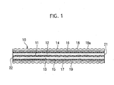
- Fig. 1 shows a layer structure of a flat belt 10, which is an embodiment of the present invention.
- the flat belt 10 is endless
- Fig. 1 shows a state in which the flat belt 10 is flattened, i.e., a state before both end portions 21 and 22 are joined.
- Fig. 1 is a vertical sectional view, in which the flat belt 10 is cut by a plane extending in the longitudinal direction (i.e., the horizontal direction in the drawing) of the flat belt 10, but the length of the flat belt 10 is shown as being extremely short for ease of indication in the drawing.
- the flat belt 10 is provided with a longitudinal reinforcement fabric 11 at the central portion in the thickness direction of the flat belt 10.
- the longitudinal reinforcement fabric 11 extends the whole length of the flat belt 10, and is provided for reinforcing the flat belt 10 along the longitudinal direction.
- thermoplastic resin layers 12 and 13 are laminated and adhered on the upper and lower sides of the longitudinal reinforcement fabric 11.
- the thermoplastic resin needs to be adhesive and flexible, and for example, thermoplastic polyurethane can be used as the thermoplastic resin.
- a first lateral reinforcement fabric 14 is laminated and adhered on an upper side of the first thermoplastic resin layer 12 in order to reinforce the flexural rigidity of the flat belt 10 in the width direction, or the lateral strength.
- a second lateral reinforcement fabric 15 is laminated and adhered on a lower side of the second thermoplastic resin layer 13 to reinforce the lateral strength.
- the lateral reinforcement fabrics 14 and 15 it is preferable to use a fabric made of nylon or polyester, which are stretchable or elastic in the longitudinal direction.
- thermoplastic resin layer 16 is laminated and adhered on an upper side of the first lateral reinforcement fabric 14, and a fourth thermoplastic resin layer 17 is laminated and adhered on a lower side of the second lateral reinforcement fabric 15.
- the third and fourth thermoplastic resin layers 16 and 17 are thermoplastic polyurethane, for example, similarly to the first and second thermoplastic resin layers 12 and 13. Namely, as the most simple structure, the thermoplastic resin layers 12, 13, 16, and 17 are made of the same material.
- a surface of the first friction layer 18 is a conveyor surface 18a, being an awled surface, which is a rugged surface having a regularly arranged convex and concave parts, so that the first friction layer 18 has a predetermined frictional coefficient to convey a subject.
- a second friction layer 19, having the same structure as the first friction layer 18, is laminated and adhered on a lower side of the fourth thermoplastic resin layer 17. Therefore, the second friction layer 19 can work as a conveyor surface.
- the third thermoplastic resin layer 16 is provided between the first lateral reinforcement fabric 14 and the first friction layer 18, the third thermoplastic resin layer 16 can be omitted, and the first friction layer 18 may be directly laminated on the upper surface of the first lateral reinforcement fabric 14, according to the object of the system.
- the fourth thermoplastic resin layer 17 provided between the second lateral reinforcement fabric 15 and the second friction layer 19 may be omitted, and the second friction layer 19 may be directly laminated on the lower side of the second lateral reinforcement fabric.
- the first friction layer 18 is provided above the upper side of the first lateral reinforcement fabric 14. Further, the second friction layer 19 is providedbelow the lower side of the second lateral reinforcement fabric 15.
- Fig. 2 is aplanview showing a state in which both endportions 21 and 22 of an intermediate product, formed in a strip-shape and having a layer structure shown in Fig. 1, face each other.
- the first end portion 21 of the intermediate product has a plurality of projections 21a appearing as isosceles triangles
- the second end portion 22 has a plurality of recesses 22a having the same shape as the projections 21a.
- the first and second end portions 21 and 22 are formed as complementary shapes, so that the projections 21a can be engaged with the recesses 22a.
- the thermoplastic resin layers 12, 13, 16, and 17 atboth endportions abut against each other. Both end portions 21 and 22 are heated and pressed against each other while engaging each other, so that the flat belt 10, formed in an endless shape, is obtained.
- both end portions 21 and 22 are formed in a saw-toothed shape in the example of Fig. 2, any complementary form can be used.
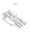
- the flat belt 10 having a structure described above, since the longitudinal reinforcement fabric 11 is provided at the center portion of the layered structure, the rigidity against the twist about the longitudinal axis is increased in comparison with a structure in which a plurality of cords are provided, so that the durability of the flat belt 10 is improved. Namely, in part of the folder-gluer process shown in Fig. 3, the flat belt 10 may be twisted about the longitudinal axis by 90 degrees in order to bend cardboard W. According to the embodiment, since the torsion rigidityof the flatbelt 10 is increased, the durability is improved, so that the life of the flat belt 10 is extended.
- a flat belt having a cord is not suitable for a device provided with a pulley having a small diameter.
- the longitudinal reinforcement fabric 11 since the longitudinal reinforcement fabric 11 is used, the flexibility of the flat belt 10 is improved, and thus, the flat belt 10 can be applied to a device with a small diameter pulley.
- first and second lateral reinforcement fabrics 14 and 15 are provided symmetrically about the longitudinal reinforcement fabric 11, flexural rigidity in the lateral direction of the flat belt 10 can be ensured.
- the third thermoplastic resin layer 16 is laminated on the upper side of the first lateral reinforcement 14, and the fourth thermoplastic resin layer 17 is laminated on the lower side of the second lateral reinforcement fabric 15.
- the first lateral reinforcement 14 is sandwiched between the first and third thermoplastic resin layers 12 and 16, and the second lateral reinforcement 15 is sandwiched between the second and fourth thermoplastic resin layers 13 and 17. Therefore, both endportions 21 and 22 are firmly joined or connected, so that the join portion is prevented from separating during use, and thus, the life of the flat belt 10 is improved.
- the first friction layer 18 is rubber
- the material can be changed in accordance with the object of use, and may be a thermoplastic elastomer, for example.
Landscapes
- Engineering & Computer Science (AREA)
- General Engineering & Computer Science (AREA)
- Mechanical Engineering (AREA)
- Belt Conveyors (AREA)
Abstract
Description
- The present invention relates to a flat belt used as part of a conveyer device or a power transmission device.
- Conventionally, there is known a flat belt, in which reinforcement fabrics are adhered on both the upper and lower surfaces of an intermediate layer in which cords are embedded, and in which the surface layers, comprised of rubber or thermoplastic elastomer, are laminated on outer surfaces of the reinforcement fabrics. In this type of flat belt, the cords are non-expandable tension members, which strengthen the flat belt in the longitudinal direction, and the reinforcement fabrics contribute to the lateral strength, i.e., the flexural rigidity of the flat belt in the width direction.
- On the other hand, in the manufacturing system known as the folder-gluer, in which cardboard that is cut in a predetermined shape, is bent and glued to form a paper box, there is known a device in which a flat belt is provided for conveying the cardboard. In this system, the flat belt, which is engaged with the cardboard, may be twisted by 90 degrees about the longitudinal axis thereof, in order to bend the cardboard, for example.
- Although a flat belt twisted about the longitudinal axis thereof needs to have excellent torsional rigidity, a conventional flat belt, as described above, has a drawback of not having sufficient torsional rigidity.
- Therefore, an object of the present invention is to provide a flat belt, which has sufficient rigidity with respect to the torsion about the longitudinal axis of the flat belt.
- According to the present invention, there is provided a flat belt comprising a longitudinal reinforcement fabric, a first thermoplastic resin layer, a second thermoplastic resin layer, a first lateral reinforcement fabric, a second lateral reinforcement fabric, and a first friction layer.
- The longitudinal reinforcement fabric reinforces the flat belt along the longitudinal direction. The first thermoplastic resin layer is laminated on an upper side of the longitudinal reinforcement fabric. The second thermoplastic resin layer is laminated on a lower side of the longitudinal reinforcement fabric. The first lateral reinforcement fabric is laminated on an upper side of the first thermoplastic resin layer to reinforce the flat belt along the lateral direction. The second lateral reinforcement fabric is laminated on a lower side of the second thermoplastic resin layer to reinforce the flat belt along the lateral direction. The first friction layer is provided above an upper side of the first lateral reinforcement fabric, and is formed with a conveyor surface for conveying a subject.
- The objects and advantages of the present invention will be better understood from the following description, with reference to the accompanying drawings in which:
- Fig. 1 is a sectional view of a flat belt of an embodiment of the present invention;
- Fig. 2 is a plan view showing a state in which both end portions of an intermediate product, formed in a strip-shape and having a layer structure shown in Fig. 1, face each other; and
- Fig. 3 is a perspective view showing a process for bending cardboard in a folder-gluer provided with the flat belt of the embodiment.
- The present invention will be described below with reference to an embodiment shown in the drawings.
- Fig. 1 shows a layer structure of a
flat belt 10, which is an embodiment of the present invention. Although theflat belt 10 is endless, Fig. 1 shows a state in which theflat belt 10 is flattened, i.e., a state before bothend portions flat belt 10 is cut by a plane extending in the longitudinal direction (i.e., the horizontal direction in the drawing) of theflat belt 10, but the length of theflat belt 10 is shown as being extremely short for ease of indication in the drawing. - The
flat belt 10 is provided with alongitudinal reinforcement fabric 11 at the central portion in the thickness direction of theflat belt 10. Thelongitudinal reinforcement fabric 11 extends the whole length of theflat belt 10, and is provided for reinforcing theflat belt 10 along the longitudinal direction. As thelongitudinal reinforcement fabric 11, it is preferable to use a fabric made of nylon or polyester, which are not substantially stretchable or elastic in the longitudinal direction. - First and second
thermoplastic resin layers longitudinal reinforcement fabric 11. The thermoplastic resin needs to be adhesive and flexible, and for example, thermoplastic polyurethane can be used as the thermoplastic resin. - A first
lateral reinforcement fabric 14 is laminated and adhered on an upper side of the firstthermoplastic resin layer 12 in order to reinforce the flexural rigidity of theflat belt 10 in the width direction, or the lateral strength. Similarly, a secondlateral reinforcement fabric 15 is laminated and adhered on a lower side of the secondthermoplastic resin layer 13 to reinforce the lateral strength. As thelateral reinforcement fabrics - A third
thermoplastic resin layer 16 is laminated and adhered on an upper side of the firstlateral reinforcement fabric 14, and a fourththermoplastic resin layer 17 is laminated and adhered on a lower side of the secondlateral reinforcement fabric 15. The third and fourththermoplastic resin layers thermoplastic resin layers thermoplastic resin layers - A
first friction layer 18, which is rubber, is laminated and adhered on an upper side of the thirdthermoplastic resin layer 16. A surface of thefirst friction layer 18 is aconveyor surface 18a, being an awled surface, which is a rugged surface having a regularly arranged convex and concave parts, so that thefirst friction layer 18 has a predetermined frictional coefficient to convey a subject. Similarly, asecond friction layer 19, having the same structure as thefirst friction layer 18, is laminated and adhered on a lower side of the fourththermoplastic resin layer 17. Therefore, thesecond friction layer 19 can work as a conveyor surface. - Thus, although, in this embodiment, the third
thermoplastic resin layer 16 is provided between the firstlateral reinforcement fabric 14 and thefirst friction layer 18, the thirdthermoplastic resin layer 16 can be omitted, and thefirst friction layer 18 may be directly laminated on the upper surface of the firstlateral reinforcement fabric 14, according to the object of the system. Similarly, the fourththermoplastic resin layer 17 provided between the secondlateral reinforcement fabric 15 and thesecond friction layer 19 may be omitted, and thesecond friction layer 19 may be directly laminated on the lower side of the second lateral reinforcement fabric. - In other words, in this embodiment, the
first friction layer 18 is provided above the upper side of the firstlateral reinforcement fabric 14. Further, thesecond friction layer 19 is providedbelow the lower side of the secondlateral reinforcement fabric 15. - Fig. 2 is aplanview showing a state in which both
endportions first end portion 21 of the intermediate product has a plurality ofprojections 21a appearing as isosceles triangles, and thesecond end portion 22 has a plurality ofrecesses 22a having the same shape as theprojections 21a. Namely, the first andsecond end portions projections 21a can be engaged with therecesses 22a. Thus, when the bothend portions thermoplastic resin layers end portions flat belt 10, formed in an endless shape, is obtained. - Although both
end portions - In the
flat belt 10, having a structure described above, since thelongitudinal reinforcement fabric 11 is provided at the center portion of the layered structure, the rigidity against the twist about the longitudinal axis is increased in comparison with a structure in which a plurality of cords are provided, so that the durability of theflat belt 10 is improved. Namely, in part of the folder-gluer process shown in Fig. 3, theflat belt 10 may be twisted about the longitudinal axis by 90 degrees in order to bend cardboard W. According to the embodiment, since the torsion rigidityof theflatbelt 10 is increased, the durability is improved, so that the life of theflat belt 10 is extended. - On the other hand, since a cord has higher flexural rigidity than fabric, a flat belt having a cord is not suitable for a device provided with a pulley having a small diameter. Conversely, in this embodiment, since the
longitudinal reinforcement fabric 11 is used, the flexibility of theflat belt 10 is improved, and thus, theflat belt 10 can be applied to a device with a small diameter pulley. - Further, in the embodiment, since the first and second
lateral reinforcement fabrics longitudinal reinforcement fabric 11, flexural rigidity in the lateral direction of theflat belt 10 can be ensured. - Furthermore, in the embodiment, other than the first and second
thermoplastic resin layers thermoplastic resin layer 16 is laminated on the upper side of the firstlateral reinforcement 14, and the fourththermoplastic resin layer 17 is laminated on the lower side of the secondlateral reinforcement fabric 15. In other words, the firstlateral reinforcement 14 is sandwiched between the first and thirdthermoplastic resin layers lateral reinforcement 15 is sandwiched between the second and fourththermoplastic resin layers endportions flat belt 10 is improved. - Note that, although, in the above embodiment, the
first friction layer 18 is rubber, the material can be changed in accordance with the object of use, and may be a thermoplastic elastomer, for example.
Claims (8)
- A flat belt comprising:a longitudinal reinforcement fabric for reinforcing said flat belt along the longitudinal direction;a first thermoplastic resin layer that is laminated on an upper side of said longitudinal reinforcement fabric;a second thermoplastic resin layer that is laminated on a lower side of said longitudinal reinforcement fabric;a first lateral reinforcement fabric that is laminated on an upper side of said first thermoplastic resin layer to reinforce said flat belt along the lateral direction;a second lateral reinforcement fabric that is laminated on a lower side of said second thermoplastic resin layer to reinforce said flat belt along the lateral direction; anda first friction layer that is provided above an upper side of said first lateral reinforcement fabric, and is formed with a conveyor surface for conveying a subject.
- A flat belt according to claim 1, further comprising a third thermoplastic resin layer provided between said first lateral reinforcement fabric and said first friction layer.
- A flat belt according to claim 1, further comprising a second friction layer that is provided on a lower side of said second lateral reinforcement fabric, and has the same structure of said first friction layer.
- A flat belt according to claim 3, further comprising a fourth thermoplastic resin layer provided between said second lateral reinforcement fabric and said second friction layer.
- A flat belt according to claim 1, wherein said first friction layer comprises rubber.
- A flat belt according to claim 1, wherein said first friction layer comprises a thermoplastic elastomer.
- A flat belt according to claim 1, wherein an intermediate product, comprising said longitudinal reinforcement fabric, said first and second thermoplastic resin layers, said first and second lateral reinforcement fabrics, and said first friction layer, is formed in a strip-shape, and has two end portions, which are formed in complementary shapes, said end portions being heated and pressed against each other while engaging each other, so that said flat belt is formed in an endless shape.
- A flat belt according to claim 7, wherein said both end portions are formed in a saw-toothed shape.
Applications Claiming Priority (1)
| Application Number | Priority Date | Filing Date | Title |
|---|---|---|---|
| JP2005116603A JP4671742B2 (en) | 2005-04-14 | 2005-04-14 | Flat belt |
Publications (3)
| Publication Number | Publication Date |
|---|---|
| EP1712813A2 true EP1712813A2 (en) | 2006-10-18 |
| EP1712813A3 EP1712813A3 (en) | 2007-05-02 |
| EP1712813B1 EP1712813B1 (en) | 2011-06-29 |
Family
ID=36677288
Family Applications (1)
| Application Number | Title | Priority Date | Filing Date |
|---|---|---|---|
| EP06112220A Expired - Lifetime EP1712813B1 (en) | 2005-04-14 | 2006-04-04 | Flat belt |
Country Status (3)
| Country | Link |
|---|---|
| US (1) | US20060234820A1 (en) |
| EP (1) | EP1712813B1 (en) |
| JP (1) | JP4671742B2 (en) |
Families Citing this family (8)
| Publication number | Priority date | Publication date | Assignee | Title |
|---|---|---|---|---|
| JP2010014194A (en) * | 2008-07-03 | 2010-01-21 | Nitta Ind Corp | Joint belt and belt joint processing method |
| EP2792904B1 (en) * | 2011-12-14 | 2016-08-10 | Bando Chemical Industries, Ltd. | Friction transmission belt and method for producing same |
| ITTO20120419A1 (en) * | 2012-05-09 | 2013-11-10 | Dayco Europe Srl | POLI-V BELT INCLUDING A LAYER OF THERMOPLASTIC MATERIAL AND A KNITTED FABRIC IMMERSED IN AN ELASTOMERIC LAYER |
| DE112013003788B4 (en) * | 2012-08-02 | 2022-04-21 | Bando Chemical Industries, Ltd. | Power transmission belt and method of making same |
| CN103496234B (en) * | 2013-10-14 | 2015-12-30 | 济南天齐特种平带有限公司 | A kind of elasticity tapes |
| WO2015111486A1 (en) * | 2014-01-22 | 2015-07-30 | ニッタ株式会社 | Flat belt |
| JP2016060557A (en) * | 2014-09-16 | 2016-04-25 | ニッタ株式会社 | Endless flat belt and method for manufacturing endless flat belt |
| JP7228953B2 (en) * | 2017-12-27 | 2023-02-27 | ニッタ株式会社 | conveyor belt |
Citations (2)
| Publication number | Priority date | Publication date | Assignee | Title |
|---|---|---|---|---|
| US3574022A (en) | 1967-02-23 | 1971-04-06 | Rost & Co H | Conveying or driving belt and method for making same |
| WO1996013374A1 (en) | 1994-10-31 | 1996-05-09 | Habasit Ag | Processing band for compacting bulk materials |
Family Cites Families (29)
| Publication number | Priority date | Publication date | Assignee | Title |
|---|---|---|---|---|
| US2423579A (en) * | 1945-02-02 | 1947-07-08 | Asa J Buren | Corrugated belting |
| US2514429A (en) * | 1945-06-27 | 1950-07-11 | Dayton Rubber Company | Double cog belt |
| US2784130A (en) * | 1953-08-12 | 1957-03-05 | Stoffel & Co | Conveyor band for film printing machines |
| US2727844A (en) * | 1954-01-11 | 1955-12-20 | Raybestos Manhattan Inc | Conveyor belt |
| US2850420A (en) * | 1955-06-14 | 1958-09-02 | Goodyear Tire & Rubber | Belt |
| US3197021A (en) * | 1962-11-28 | 1965-07-27 | Russell Mfg Co | Ribbed conveyor belt |
| GB1105744A (en) * | 1964-07-21 | 1968-03-13 | Dunlop Co Ltd | Improvements relating to belting |
| US3556892A (en) * | 1967-12-18 | 1971-01-19 | American Biltrite Rubber Co | Method of manufacture of conveyor belt |
| US3900627A (en) * | 1971-12-17 | 1975-08-19 | Pirelli | Conveyor belt |
| GB1400799A (en) * | 1972-11-14 | 1975-07-23 | Goodyear Tire & Rubber | V-belts |
| US3941005A (en) * | 1975-03-03 | 1976-03-02 | The Gates Rubber Company | Power transmission belt |
| US4216856A (en) * | 1975-04-25 | 1980-08-12 | Dunlop Limited | Reinforcement for elastomeric articles |
| US3987684A (en) * | 1975-07-28 | 1976-10-26 | Dayco Corporation | Endless power transmission belt structure |
| JPS5350989U (en) * | 1976-10-05 | 1978-04-28 | ||
| GB1568450A (en) * | 1977-04-19 | 1980-05-29 | Simon Container Mach Ltd | Apparatus for folding box blanks |
| CH618138A5 (en) * | 1977-04-28 | 1980-07-15 | Habasit Ag | |
| JPS579343A (en) * | 1980-06-19 | 1982-01-18 | Mitsuboshi Belting Ltd | Joining of conveyor belt |
| US4371580A (en) * | 1982-01-26 | 1983-02-01 | Morrison Company, Inc. | Three-ply belting material |
| US4410314A (en) * | 1982-02-11 | 1983-10-18 | Dayco Corporation | Endless power transmission V-belt construction and method of making the same |
| US4518647A (en) * | 1984-06-11 | 1985-05-21 | Morrison Company, Inc. | Agricultural belting material |
| EP0298459A3 (en) * | 1987-07-10 | 1989-05-31 | Aisin Seiki Kabushiki Kaisha | A belt |
| JPS6464909A (en) * | 1987-09-02 | 1989-03-10 | Nitta Kk | Splice structure for conveyer belt |
| DE3836936C2 (en) * | 1988-10-31 | 1998-05-20 | Mitsuboshi Belting Ltd | Power transmission belt |
| DE3908981A1 (en) * | 1989-03-18 | 1990-09-27 | Bahmueller Masch W | FOLDING MACHINE |
| DE4418590C2 (en) * | 1994-05-27 | 1996-11-21 | Clouth Gummiwerke Ag | Composite laminate, in particular conveyor belt |
| CH690073A5 (en) * | 1995-10-17 | 2000-04-14 | Habasit Ag | Multilayer structured Faltschachtelband. |
| US5941168A (en) * | 1998-04-14 | 1999-08-24 | Agco Corporation | Silage round baler |
| US6994209B2 (en) * | 2001-02-02 | 2006-02-07 | Habasit Ag | Conveyor belt with a polymer surface coating containing an antimicrobial additive |
| JP2002372106A (en) * | 2001-06-13 | 2002-12-26 | Bando Chem Ind Ltd | Conveyor belt containing aramid core and method of joining the conveyor belt containing aramid core |
-
2005
- 2005-04-14 JP JP2005116603A patent/JP4671742B2/en not_active Expired - Lifetime
-
2006
- 2006-03-31 US US11/393,870 patent/US20060234820A1/en not_active Abandoned
- 2006-04-04 EP EP06112220A patent/EP1712813B1/en not_active Expired - Lifetime
Patent Citations (2)
| Publication number | Priority date | Publication date | Assignee | Title |
|---|---|---|---|---|
| US3574022A (en) | 1967-02-23 | 1971-04-06 | Rost & Co H | Conveying or driving belt and method for making same |
| WO1996013374A1 (en) | 1994-10-31 | 1996-05-09 | Habasit Ag | Processing band for compacting bulk materials |
Also Published As
| Publication number | Publication date |
|---|---|
| JP4671742B2 (en) | 2011-04-20 |
| EP1712813B1 (en) | 2011-06-29 |
| US20060234820A1 (en) | 2006-10-19 |
| EP1712813A3 (en) | 2007-05-02 |
| JP2006290601A (en) | 2006-10-26 |
Similar Documents
| Publication | Publication Date | Title |
|---|---|---|
| US4365965A (en) | V-Block belt | |
| JP2011133029A (en) | Flat belt | |
| EP1712813B1 (en) | Flat belt | |
| JPH07196115A (en) | Module link and belt for conveyor belt | |
| WO2011027380A1 (en) | Flat belt | |
| US9103406B2 (en) | Transmission vee-belt comprising an elastically deformable peripheral cushion | |
| US6565689B2 (en) | Non-slip conveyor and method for producing same | |
| JP2519700B2 (en) | V-belt for continuously variable transmission | |
| US20040163935A1 (en) | Non-slip conveyor and method for producing same | |
| JP2001153186A (en) | Flat belt | |
| JP2004534181A (en) | Endless transmission belt | |
| US6196378B1 (en) | Conveyor belt connector and method | |
| JPS61286637A (en) | Transmission belt | |
| JP2016088681A (en) | Flat belt | |
| US7241354B2 (en) | Non-slip conveyor and method for producing same | |
| EP1849722A1 (en) | Conveyance belt with guide | |
| JPH0333536A (en) | Transmission belt and manufacture thereof | |
| JP2016060557A (en) | Endless flat belt and method for manufacturing endless flat belt | |
| JP6486755B2 (en) | Transmission belt | |
| JP3055423U (en) | Crop transport belt | |
| JP4759431B2 (en) | Belt joint processing method | |
| JP4520573B2 (en) | Belt joint structure | |
| JPS60121335A (en) | Rubber ring for preventing wear of air spring | |
| JPH0518514Y2 (en) | ||
| JP3004708U (en) | Joint structure of toothed belt for transportation |
Legal Events
| Date | Code | Title | Description |
|---|---|---|---|
| PUAI | Public reference made under article 153(3) epc to a published international application that has entered the european phase |
Free format text: ORIGINAL CODE: 0009012 |
|
| AK | Designated contracting states |
Kind code of ref document: A2 Designated state(s): AT BE BG CH CY CZ DE DK EE ES FI FR GB GR HU IE IS IT LI LT LU LV MC NL PL PT RO SE SI SK TR |
|
| AX | Request for extension of the european patent |
Extension state: AL BA HR MK YU |
|
| PUAL | Search report despatched |
Free format text: ORIGINAL CODE: 0009013 |
|
| AK | Designated contracting states |
Kind code of ref document: A3 Designated state(s): AT BE BG CH CY CZ DE DK EE ES FI FR GB GR HU IE IS IT LI LT LU LV MC NL PL PT RO SE SI SK TR |
|
| AX | Request for extension of the european patent |
Extension state: AL BA HR MK YU |
|
| 17P | Request for examination filed |
Effective date: 20070920 |
|
| 17Q | First examination report despatched |
Effective date: 20071031 |
|
| AKX | Designation fees paid |
Designated state(s): CH DE FR GB IT LI NL |
|
| GRAP | Despatch of communication of intention to grant a patent |
Free format text: ORIGINAL CODE: EPIDOSNIGR1 |
|
| GRAS | Grant fee paid |
Free format text: ORIGINAL CODE: EPIDOSNIGR3 |
|
| GRAA | (expected) grant |
Free format text: ORIGINAL CODE: 0009210 |
|
| AK | Designated contracting states |
Kind code of ref document: B1 Designated state(s): CH DE FR GB IT LI NL |
|
| REG | Reference to a national code |
Ref country code: GB Ref legal event code: FG4D |
|
| REG | Reference to a national code |
Ref country code: CH Ref legal event code: EP |
|
| REG | Reference to a national code |
Ref country code: CH Ref legal event code: NV Representative=s name: SCHNEIDER FELDMANN AG PATENT- UND MARKENANWAELTE |
|
| REG | Reference to a national code |
Ref country code: DE Ref legal event code: R096 Ref document number: 602006022748 Country of ref document: DE Effective date: 20110818 |
|
| REG | Reference to a national code |
Ref country code: NL Ref legal event code: T3 |
|
| PLBE | No opposition filed within time limit |
Free format text: ORIGINAL CODE: 0009261 |
|
| STAA | Information on the status of an ep patent application or granted ep patent |
Free format text: STATUS: NO OPPOSITION FILED WITHIN TIME LIMIT |
|
| 26N | No opposition filed |
Effective date: 20120330 |
|
| REG | Reference to a national code |
Ref country code: DE Ref legal event code: R097 Ref document number: 602006022748 Country of ref document: DE Effective date: 20120330 |
|
| REG | Reference to a national code |
Ref country code: DE Ref legal event code: R082 Ref document number: 602006022748 Country of ref document: DE Representative=s name: SCHAUMBURG & PARTNER PATENTANWAELTE GBR, DE Ref country code: DE Ref legal event code: R082 Ref document number: 602006022748 Country of ref document: DE Representative=s name: SCHAUMBURG UND PARTNER PATENTANWAELTE MBB, DE |
|
| REG | Reference to a national code |
Ref country code: FR Ref legal event code: PLFP Year of fee payment: 11 |
|
| REG | Reference to a national code |
Ref country code: FR Ref legal event code: PLFP Year of fee payment: 12 |
|
| REG | Reference to a national code |
Ref country code: FR Ref legal event code: PLFP Year of fee payment: 13 |
|
| REG | Reference to a national code |
Ref country code: CH Ref legal event code: PFA Owner name: NITTA CORPORATION, JP Free format text: FORMER OWNER: NITTA CORPORATION, JP |
|
| P01 | Opt-out of the competence of the unified patent court (upc) registered |
Effective date: 20230526 |
|
| PGFP | Annual fee paid to national office [announced via postgrant information from national office to epo] |
Ref country code: NL Payment date: 20250418 Year of fee payment: 20 |
|
| PGFP | Annual fee paid to national office [announced via postgrant information from national office to epo] |
Ref country code: DE Payment date: 20250422 Year of fee payment: 20 |
|
| PGFP | Annual fee paid to national office [announced via postgrant information from national office to epo] |
Ref country code: GB Payment date: 20250418 Year of fee payment: 20 |
|
| PGFP | Annual fee paid to national office [announced via postgrant information from national office to epo] |
Ref country code: IT Payment date: 20250424 Year of fee payment: 20 |
|
| PGFP | Annual fee paid to national office [announced via postgrant information from national office to epo] |
Ref country code: FR Payment date: 20250423 Year of fee payment: 20 |
|
| PGFP | Annual fee paid to national office [announced via postgrant information from national office to epo] |
Ref country code: CH Payment date: 20250501 Year of fee payment: 20 |
|
| REG | Reference to a national code |
Ref country code: CH Ref legal event code: H14 Free format text: ST27 STATUS EVENT CODE: U-0-0-H10-H14 (AS PROVIDED BY THE NATIONAL OFFICE) Effective date: 20260404 Ref country code: DE Ref legal event code: R071 Ref document number: 602006022748 Country of ref document: DE |
|
| REG | Reference to a national code |
Ref country code: NL Ref legal event code: MK Effective date: 20260403 |
|
| REG | Reference to a national code |
Ref country code: GB Ref legal event code: PE20 Expiry date: 20260403 |