EP1712403A1 - Method for fitting a seat sensor into a seat cushion - Google Patents
Method for fitting a seat sensor into a seat cushion Download PDFInfo
- Publication number
- EP1712403A1 EP1712403A1 EP05102882A EP05102882A EP1712403A1 EP 1712403 A1 EP1712403 A1 EP 1712403A1 EP 05102882 A EP05102882 A EP 05102882A EP 05102882 A EP05102882 A EP 05102882A EP 1712403 A1 EP1712403 A1 EP 1712403A1
- Authority
- EP
- European Patent Office
- Prior art keywords
- sensor
- seat cushion
- mould
- seat
- sensor portion
- Prior art date
- Legal status (The legal status is an assumption and is not a legal conclusion. Google has not performed a legal analysis and makes no representation as to the accuracy of the status listed.)
- Withdrawn
Links
- 238000000034 method Methods 0.000 title claims abstract description 33
- 238000005187 foaming Methods 0.000 claims abstract description 27
- 239000002184 metal Substances 0.000 claims description 7
- 238000001514 detection method Methods 0.000 description 6
- 239000006260 foam Substances 0.000 description 5
- 238000003780 insertion Methods 0.000 description 5
- 230000037431 insertion Effects 0.000 description 5
- 238000011156 evaluation Methods 0.000 description 4
- 239000006261 foam material Substances 0.000 description 3
- 239000000853 adhesive Substances 0.000 description 2
- 230000001070 adhesive effect Effects 0.000 description 2
- 239000000463 material Substances 0.000 description 2
- 229920005830 Polyurethane Foam Polymers 0.000 description 1
- 230000004075 alteration Effects 0.000 description 1
- 239000012876 carrier material Substances 0.000 description 1
- 238000002788 crimping Methods 0.000 description 1
- 230000003247 decreasing effect Effects 0.000 description 1
- 238000002347 injection Methods 0.000 description 1
- 239000007924 injection Substances 0.000 description 1
- 230000010354 integration Effects 0.000 description 1
- 239000010985 leather Substances 0.000 description 1
- 230000035515 penetration Effects 0.000 description 1
- 238000007493 shaping process Methods 0.000 description 1
- 239000007787 solid Substances 0.000 description 1
- 239000004753 textile Substances 0.000 description 1
Images

Classifications
-
- B—PERFORMING OPERATIONS; TRANSPORTING
- B60—VEHICLES IN GENERAL
- B60R—VEHICLES, VEHICLE FITTINGS, OR VEHICLE PARTS, NOT OTHERWISE PROVIDED FOR
- B60R21/00—Arrangements or fittings on vehicles for protecting or preventing injuries to occupants or pedestrians in case of accidents or other traffic risks
- B60R21/01—Electrical circuits for triggering passive safety arrangements, e.g. airbags, safety belt tighteners, in case of vehicle accidents or impending vehicle accidents
- B60R21/015—Electrical circuits for triggering passive safety arrangements, e.g. airbags, safety belt tighteners, in case of vehicle accidents or impending vehicle accidents including means for detecting the presence or position of passengers, passenger seats or child seats, and the related safety parameters therefor, e.g. speed or timing of airbag inflation in relation to occupant position or seat belt use
- B60R21/01512—Passenger detection systems
-
- B—PERFORMING OPERATIONS; TRANSPORTING
- B60—VEHICLES IN GENERAL
- B60N—SEATS SPECIALLY ADAPTED FOR VEHICLES; VEHICLE PASSENGER ACCOMMODATION NOT OTHERWISE PROVIDED FOR
- B60N2/00—Seats specially adapted for vehicles; Arrangement or mounting of seats in vehicles
- B60N2/002—Seats provided with an occupancy detection means mounted therein or thereon
- B60N2/0021—Seats provided with an occupancy detection means mounted therein or thereon characterised by the type of sensor or measurement
- B60N2/003—Seats provided with an occupancy detection means mounted therein or thereon characterised by the type of sensor or measurement characterised by the sensor mounting location in or on the seat
- B60N2/0033—Seats provided with an occupancy detection means mounted therein or thereon characterised by the type of sensor or measurement characterised by the sensor mounting location in or on the seat mounted on or in the foam cushion
-
- B—PERFORMING OPERATIONS; TRANSPORTING
- B60—VEHICLES IN GENERAL
- B60N—SEATS SPECIALLY ADAPTED FOR VEHICLES; VEHICLE PASSENGER ACCOMMODATION NOT OTHERWISE PROVIDED FOR
- B60N2/00—Seats specially adapted for vehicles; Arrangement or mounting of seats in vehicles
- B60N2/70—Upholstery springs ; Upholstery
- B60N2/7017—Upholstery springs ; Upholstery characterised by the manufacturing process; manufacturing upholstery or upholstery springs not otherwise provided for
-
- B—PERFORMING OPERATIONS; TRANSPORTING
- B60—VEHICLES IN GENERAL
- B60N—SEATS SPECIALLY ADAPTED FOR VEHICLES; VEHICLE PASSENGER ACCOMMODATION NOT OTHERWISE PROVIDED FOR
- B60N2210/00—Sensor types, e.g. for passenger detection systems or for controlling seats
- B60N2210/40—Force or pressure sensors
-
- B—PERFORMING OPERATIONS; TRANSPORTING
- B60—VEHICLES IN GENERAL
- B60R—VEHICLES, VEHICLE FITTINGS, OR VEHICLE PARTS, NOT OTHERWISE PROVIDED FOR
- B60R21/00—Arrangements or fittings on vehicles for protecting or preventing injuries to occupants or pedestrians in case of accidents or other traffic risks
- B60R21/01—Electrical circuits for triggering passive safety arrangements, e.g. airbags, safety belt tighteners, in case of vehicle accidents or impending vehicle accidents
- B60R2021/01006—Mounting of electrical components in vehicles
Definitions
- An automotive vehicle seat generally comprises a foamed seat cushion e.g. made of PU foam, which is arranged on a solid backing structure and covered by a seat trim made of a textile material or of leather.
- the seat cushion comprises one or more grooves, which extend from the upper seating surface of the seat cushion into the seat cushion.
- a seat cushion typically comprises e.g. two lengthwise extending grooves separating a central seating surface from the side bolsters and one or more transverse grooves extending between the opposite lengthwise grooves.
- the grooves are typically used as crimping channels for attaching the seat trim to the seat cushion.
- a metal wire is embedded in the seat cushion so as to extend along the grooves and to be is partially exposed inside the grooves.
- the seat trim can then be attached to the exposed portions of the metal wire e.g. by means of hook shaped elements.
- seat sensors for detecting one or more parameters relating to a seating condition with respect to the vehicle seats. The determined parameters are then used in the control of secondary restraint systems, driver warning systems and/or comfort systems.
- Specific examples of such seat sensors comprise passenger detection sensors, child seat presence and orientation detection sensors, occupant classification sensors, seat belt warning sensors, etc.
- the passenger presence detectors, the occupant classification sensors and the seat belt reminder sensors are usually configured as thin foil-type sensors comprising e.g.
- a plurality of pressure sensors interconnected by flexible strips which are to be associated to a seating surface of the vehicle seat.
- Other sensors such as e.g. the child seat presence and orientation detection sensors comprise two or more antenna structures arranged on a thin flexible carrier material. All these sensors are generally configured to be associated to the seating surface of the vehicle seat, normally between the seat cushion and the seat trim.
- the flexible sensor structures have to cover a large area of the seating surface. This means on the other hand, that if a sensor is placed on top of the seat cushion, the sensor or the flexible strips of the sensor respectively have to cross the grooves of the seat cushion at different locations.
- the crossing of the sensor strips is typically achieved by providing sensor channels extending transversely to the grooves from the upper seating surface to the bottom of the grooves. During assembly of the sensor and the seat cushion, the sensor strips are inserted into these sensor channels so as to cross the grooves at their bottom.
- This technique is suitable for seat cushions with shallow grooves and/or seat and sensor configurations which lead to a small number of crossing points between sensor strips and crimp channels. If however the seat cushion comprises a high number of transverse crimp channels, which in addition are very deep, this classical assembly method is rendered virtually impossible.
- the object of the present invention is accordingly to provide a different method for assembling a seat sensor on a seat cushion.
- This object is achieved by a method for fitting a sensor onto a seat cushion according to claim 1.
- This method is specifically suitable for the assembly of a seat sensor onto a seat cushion, wherein the seat cushion comprises a seating surface having a central region, said central region of said seating surface being at least partially delimited by a groove extending from said seating surface into said seat cushion, and wherein said sensor comprises a first sensor portion to be arranged at least partially at a periphery of said central region.
- the method of the present invention comprises the steps of providing a mould for foaming said seat cushion, said mould comprising at least one ridge designed for forming said groove into said seating surface of said seat cushion; arranging said first sensor portion in said mould on said at least one ridge, and foaming said seat cushion, thereby integrating at least part of said first sensor portion into said seat cushion.
- the sensor or the first sensor portion is at least partially foamed into the seat cushion instead of placing the sensor onto the seating surface.
- the sensor is integrated at a depth, which substantially corresponds to the depth of the grooves, such that crossings between the sensor strips and the grooves are no longer critical.
- the method according to the present invention eliminates the need for complicated sensor assembly and is thus specifically suitable for seats having a high number of grooves and/or for seats where the grooves are very deep. Furthermore, the seat assembly is radically shortened, as the sensor is already integrated after the foaming process. This is especially important in today's just in time delivery conditions. Finally, the integration of the sensor into the seat cushion foam ensures a reliable positioning of the sensor during the vehicle lifetime, so that detection accuracy is preserved over lifetime.
- the sensor comprises a connection strip, which enables connection of the sensor to an external evaluation unit. During the arrangement of the sensor into the mould, this connection strip is lead out of the mould and arranged so that the extremity carrying the connection terminals extends outside of the mould.
- the first sensor portion comprises e.g. an antenna arrangement of a child seat presence and orientation detection (CPOD) system.
- CPOD child seat presence and orientation detection
- the antenna arrangement comprises e.g. one single receiving antenna loop, which has to be associated to the seating surface so as to substantially surround the central portion of the seating surface.
- the antenna arrangement further comprises two emitting antenna loops, each of which should surround one half of the central portion. According to the present invention, the antenna loops are foamed into the seat cushion at a depth, which corresponds substantially to the depth of the crimp channels.
- said step of arranging said first sensor portion in said mould comprises the steps of attaching auxiliary inserts onto said ridge and fastening said first sensor portion onto said auxiliary inserts.
- the auxiliary inserts may be placed onto the ridges of the mould and after their correct positioning in the seat the sensor may be attached to the auxiliary inserts.
- the auxiliary inserts may be fastened to the first sensor portion prior to their arrangement into the mould and only subsequently attached at their respective positions on the mould ridges.
- the auxiliary inserts should be designed so as to be easily removable from the ridges after the foaming process. In fact, during the foaming, the auxiliary inserts are foamed together with the first sensor portion into the seat cushion and thus remain a part of the seat cushion. It follows, that the auxiliary inserts are removed from the mould together with the seat cushion and should accordingly be easily separable from the ridges.
- the auxiliary inserts comprise a base portion and a clip portion extending from said base portion, said clip portion for removably clipping said auxiliary insert onto an upper edge of said ridge.
- a clipable insert is easily attached to the ridges and thus ensures a reliable positioning of the inserts with respect to the ridges during foaming.
- the clip portion extends from the bottom of the groove along the lateral walls of the groove.
- the first sensor portion is preferably attached to the base portion of the auxiliary insert.
- the sensor strips may be fastened by any suitable means such as e.g. clips, hook and loop fasteners, rivets or the like or by an adhesive.
- the sensor strips may be provided with specific fastening lugs for fastening the sensor to the auxiliary inserts.
- These fastening lugs may be positioned asymmetrically on the sensor so as to ensure a correct positioning of the sensor and to avoid the sensor being arranged upside down.
- the auxiliary insert may be a designated part, which is only used to temporarily attach the first sensor portion onto the ridges of the mould.
- the auxiliary inserts may serve other purposes e.g. to arrange other elements into the mould prior to the foaming step.
- the auxiliary inserts may e.g. comprise trim hooks, which are integrated into the seat cushion foam for later attachment of the seat trim.
- auxiliary inserts are adapted to position a metal wire into said mould, said metal wire extending along said ridge for being at least partially foamed into said cushion.
- the metal wire partially foamed into the cushion can then serve for attaching a seat upholstery or seat trim after the foaming of the cushion.
- the seat sensor may comprise a second sensor portion to be arranged on top of said seating surface of said seat cushion. This is e.g. the case for seat belt reminder seat sensors, which are arranged in the rear area of the seating surface for detecting the presence of a passenger on the seat.
- the seat belt reminder sensor comprises several pressure sensitive cells, which should be arranged between the seat cushion and the seat trim.
- the method may comprise the further step of inserting said second sensor portion into a secondary cavity within said mould.
- the secondary cavity is e.g. arranged in the mould portion forming the upper seating surface of the seat cushion, e.g. the bottom of the mould, as the foam cushions are traditionally foamed upside down.
- the secondary cavity is preferably closed (towards the main mould cavity) by means of a cover, so that during the foaming process, a penetration of the foam material into the secondary cavity is prevented.
- the second sensor portion is removed from the cavity and remains freely accessible above the seating surface.
- the second sensor portion also comprises a connection strip enabling the second sensor portion to be connected to an evaluation unit.
- connection strip of the second sensor portion extends from the secondary cavity through the main mould cavity to the location, at which the connection strip of the first sensor portion is lead out of the mould. Both connection strips are accordingly lead out of the mould at the same location, thus enabling the connection of the different sensor portions at the same location.
- said first sensor portion and said second sensor portion are furthermore connected to a common connection terminal by means of their flexible connection strips, thus enabling connection of the different sensor elements by means of a single connector.
- the common terminal also ensures a correct positioning of the second seat portion once the first sensor portion is correctly positioned, thus preventing the second sensor portion being arranged upside down.
- connection strip of the second sensor portion is foamed into the seat cushion, thus ensuring a reliable positioning of the second sensor portion with respect to the seating surface of the seat cushion.
- the second sensor portion is finally attached to the seating surface by the trim material.
- this embodiment of the present method enables a reliable positioning of the second sensor portion by foaming, without subjecting the second sensor portion itself to the foaming process conditions, e.g. as high temperature or the like.
- the second sensor portion is shielded from the foam by means of the secondary cavity cover, so that no alteration of the sensor characteristic by temperature may occur.
- the second sensor portion may further be protected by insertion into a felt pocket or the like prior to its insertion into the secondary cavity.
Landscapes
- Engineering & Computer Science (AREA)
- Mechanical Engineering (AREA)
- Aviation & Aerospace Engineering (AREA)
- Transportation (AREA)
- Manufacturing & Machinery (AREA)
- Seats For Vehicles (AREA)
- Casting Or Compression Moulding Of Plastics Or The Like (AREA)
- Chair Legs, Seat Parts, And Backrests (AREA)
Abstract
A method for fitting a sensor onto a seat cushion is disclosed, which is specifically suitable for the assembly of a seat sensor onto a seat cushion, wherein the seat cushion comprises a seating surface having a central region, said central region of said seating surface being at least partially delimited by a groove extending from said seating surface into said seat cushion, and wherein said sensor comprises a first sensor portion to be arranged at least partially at a periphery of said central region. The method comprises the steps of providing a mould (10) for foaming said seat cushion, said mould comprising at least one ridge (14) designed for forming said groove into said seating surface of said seat cushion; arranging said first sensor portion (18) in said mould on said at least one ridge (14), and foaming said seat cushion, thereby integrating at least part of said first sensor (18) portion into said seat cushion.
Description
- The present invention relates to a method for fitting a seat sensor to a seat cushion.
An automotive vehicle seat generally comprises a foamed seat cushion e.g. made of PU foam, which is arranged on a solid backing structure and covered by a seat trim made of a textile material or of leather. The seat cushion comprises one or more grooves, which extend from the upper seating surface of the seat cushion into the seat cushion. A seat cushion typically comprises e.g. two lengthwise extending grooves separating a central seating surface from the side bolsters and one or more transverse grooves extending between the opposite lengthwise grooves.
The grooves are typically used as crimping channels for attaching the seat trim to the seat cushion. For this purpose, a metal wire is embedded in the seat cushion so as to extend along the grooves and to be is partially exposed inside the grooves. The seat trim can then be attached to the exposed portions of the metal wire e.g. by means of hook shaped elements.
In the automotive art, it is furthermore well known to use seat sensors for detecting one or more parameters relating to a seating condition with respect to the vehicle seats. The determined parameters are then used in the control of secondary restraint systems, driver warning systems and/or comfort systems. Specific examples of such seat sensors comprise passenger detection sensors, child seat presence and orientation detection sensors, occupant classification sensors, seat belt warning sensors, etc.
The passenger presence detectors, the occupant classification sensors and the seat belt reminder sensors are usually configured as thin foil-type sensors comprising e.g. a plurality of pressure sensors interconnected by flexible strips, which are to be associated to a seating surface of the vehicle seat. Other sensors, such as e.g. the child seat presence and orientation detection sensors comprise two or more antenna structures arranged on a thin flexible carrier material. All these sensors are generally configured to be associated to the seating surface of the vehicle seat, normally between the seat cushion and the seat trim.
Depending on the sensor type, the flexible sensor structures have to cover a large area of the seating surface. This means on the other hand, that if a sensor is placed on top of the seat cushion, the sensor or the flexible strips of the sensor respectively have to cross the grooves of the seat cushion at different locations. The crossing of the sensor strips is typically achieved by providing sensor channels extending transversely to the grooves from the upper seating surface to the bottom of the grooves. During assembly of the sensor and the seat cushion, the sensor strips are inserted into these sensor channels so as to cross the grooves at their bottom.
This technique is suitable for seat cushions with shallow grooves and/or seat and sensor configurations which lead to a small number of crossing points between sensor strips and crimp channels. If however the seat cushion comprises a high number of transverse crimp channels, which in addition are very deep, this classical assembly method is rendered virtually impossible. - The object of the present invention is accordingly to provide a different method for assembling a seat sensor on a seat cushion.
- This object is achieved by a method for fitting a sensor onto a seat cushion according to claim 1. This method is specifically suitable for the assembly of a seat sensor onto a seat cushion, wherein the seat cushion comprises a seating surface having a central region, said central region of said seating surface being at least partially delimited by a groove extending from said seating surface into said seat cushion, and wherein said sensor comprises a first sensor portion to be arranged at least partially at a periphery of said central region.
- In order to overcome the abovementioned problems, the method of the present invention comprises the steps of
providing a mould for foaming said seat cushion, said mould comprising at least one ridge designed for forming said groove into said seating surface of said seat cushion;
arranging said first sensor portion in said mould on said at least one ridge, and
foaming said seat cushion, thereby integrating at least part of said first sensor portion into said seat cushion.
According to the present invention, the sensor or the first sensor portion is at least partially foamed into the seat cushion instead of placing the sensor onto the seating surface. The sensor is integrated at a depth, which substantially corresponds to the depth of the grooves, such that crossings between the sensor strips and the grooves are no longer critical. The method according to the present invention eliminates the need for complicated sensor assembly and is thus specifically suitable for seats having a high number of grooves and/or for seats where the grooves are very deep.
Furthermore, the seat assembly is radically shortened, as the sensor is already integrated after the foaming process. This is especially important in today's just in time delivery conditions. Finally, the integration of the sensor into the seat cushion foam ensures a reliable positioning of the sensor during the vehicle lifetime, so that detection accuracy is preserved over lifetime.
It will be noted, that the sensor comprises a connection strip, which enables connection of the sensor to an external evaluation unit. During the arrangement of the sensor into the mould, this connection strip is lead out of the mould and arranged so that the extremity carrying the connection terminals extends outside of the mould. It follows that after the foaming of the seat cushion, the connection terminals are accessible outside of the cushion for later connection of the sensor to the evaluation unit.
The first sensor portion comprises e.g. an antenna arrangement of a child seat presence and orientation detection (CPOD) system. Such a CPOD system is e.g. disclosed inEP-A-0 708 002 . The antenna arrangement comprises e.g. one single receiving antenna loop, which has to be associated to the seating surface so as to substantially surround the central portion of the seating surface. The antenna arrangement further comprises two emitting antenna loops, each of which should surround one half of the central portion.
According to the present invention, the antenna loops are foamed into the seat cushion at a depth, which corresponds substantially to the depth of the crimp channels. It follows that the distance between the lengthwise extending grooves no longer limits the dimensions (e.g. the width) of the antenna loops. In fact, as the crossing between the antenna loops and the grooves is not critical, the antenna loops may be dimensioned so as to extend beyond the grooves, thus increasing the total area of the antenna loops. This increase of the antenna loop area compensates the decreased detection height of the sensor due to its arrangement at a certain depth below the seating surface.
In a preferred embodiment of the invention, said step of arranging said first sensor portion in said mould comprises the steps of attaching auxiliary inserts onto said ridge and fastening said first sensor portion onto said auxiliary inserts. The auxiliary inserts may be placed onto the ridges of the mould and after their correct positioning in the seat the sensor may be attached to the auxiliary inserts. Alternatively, the auxiliary inserts may be fastened to the first sensor portion prior to their arrangement into the mould and only subsequently attached at their respective positions on the mould ridges.
It will be appreciated that the auxiliary inserts should be designed so as to be easily removable from the ridges after the foaming process. In fact, during the foaming, the auxiliary inserts are foamed together with the first sensor portion into the seat cushion and thus remain a part of the seat cushion. It follows, that the auxiliary inserts are removed from the mould together with the seat cushion and should accordingly be easily separable from the ridges.
In a possible embodiment, the auxiliary inserts comprise a base portion and a clip portion extending from said base portion, said clip portion for removably clipping said auxiliary insert onto an upper edge of said ridge. Such a clipable insert is easily attached to the ridges and thus ensures a reliable positioning of the inserts with respect to the ridges during foaming. It should be noted that after the foaming process, the clip portion extends from the bottom of the groove along the lateral walls of the groove. The first sensor portion is preferably attached to the base portion of the auxiliary insert. The sensor strips may be fastened by any suitable means such as e.g. clips, hook and loop fasteners, rivets or the like or by an adhesive.
It will be appreciated, that the sensor strips may be provided with specific fastening lugs for fastening the sensor to the auxiliary inserts. These fastening lugs may be positioned asymmetrically on the sensor so as to ensure a correct positioning of the sensor and to avoid the sensor being arranged upside down.
The auxiliary insert may be a designated part, which is only used to temporarily attach the first sensor portion onto the ridges of the mould. In a different embodiment, the auxiliary inserts may serve other purposes e.g. to arrange other elements into the mould prior to the foaming step. The auxiliary inserts may e.g. comprise trim hooks, which are integrated into the seat cushion foam for later attachment of the seat trim. Alternatively said auxiliary inserts are adapted to position a metal wire into said mould, said metal wire extending along said ridge for being at least partially foamed into said cushion. The metal wire partially foamed into the cushion can then serve for attaching a seat upholstery or seat trim after the foaming of the cushion.
Depending on the application, the seat sensor may comprise a second sensor portion to be arranged on top of said seating surface of said seat cushion. This is e.g. the case for seat belt reminder seat sensors, which are arranged in the rear area of the seating surface for detecting the presence of a passenger on the seat. The seat belt reminder sensor comprises several pressure sensitive cells, which should be arranged between the seat cushion and the seat trim. In this case, the method may comprise the further step of inserting said second sensor portion into a secondary cavity within said mould.
The secondary cavity is e.g. arranged in the mould portion forming the upper seating surface of the seat cushion, e.g. the bottom of the mould, as the foam cushions are traditionally foamed upside down. After insertion of the second sensor portion, the secondary cavity is preferably closed (towards the main mould cavity) by means of a cover, so that during the foaming process, a penetration of the foam material into the secondary cavity is prevented. After the foaming process, the second sensor portion is removed from the cavity and remains freely accessible above the seating surface.
The second sensor portion also comprises a connection strip enabling the second sensor portion to be connected to an evaluation unit. The arrangement of the second sensor in the mould is preferably such that the connection strip of the second sensor portion extends from the secondary cavity through the main mould cavity to the location, at which the connection strip of the first sensor portion is lead out of the mould. Both connection strips are accordingly lead out of the mould at the same location, thus enabling the connection of the different sensor portions at the same location. In a preferred embodiment of the sensor, said first sensor portion and said second sensor portion are furthermore connected to a common connection terminal by means of their flexible connection strips, thus enabling connection of the different sensor elements by means of a single connector. The common terminal also ensures a correct positioning of the second seat portion once the first sensor portion is correctly positioned, thus preventing the second sensor portion being arranged upside down.
It will be noted, that the connection strip of the second sensor portion is foamed into the seat cushion, thus ensuring a reliable positioning of the second sensor portion with respect to the seating surface of the seat cushion. The second sensor portion is finally attached to the seating surface by the trim material. It will be noted, that this embodiment of the present method enables a reliable positioning of the second sensor portion by foaming, without subjecting the second sensor portion itself to the foaming process conditions, e.g. as high temperature or the like. In fact, during the foaming process the second sensor portion is shielded from the foam by means of the secondary cavity cover, so that no alteration of the sensor characteristic by temperature may occur. It remains to be noted, that the second sensor portion may further be protected by insertion into a felt pocket or the like prior to its insertion into the secondary cavity. - The present invention will be more apparent from the following description of several not limiting embodiments with reference to the attached drawings, wherein
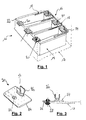
- Fig.1:
- shows a schematic representation of an interior of a mould portion for foaming a cushion seat,
- Fig.2:
- an elevation view of an auxiliary insert for attaching the sensor onto the mould ridges;
- Fig.3:
- a section view of the sensor being fastened to the auxiliary insert;
- Fig.4:
- a section view of the mould after the insertion of the first and second sensor portion;
- Fig.5:
- a view of a combined sensor.
According to the present invention, a (partially shown)
The correct arrangement and the positioning of the
The
Fig. 4 shows a cross-section of a
The first sensor portion comprises several flexible sensor strips 118 and a
The
The
Claims (7)
- Method for fitting a sensor onto a seat cushion, wherein said seat cushion comprises a seating surface having a central region, said central region of said seating surface being at least partially delimited by a groove extending from said seating surface into said seat cushion, and wherein said sensor comprises a first sensor portion to be arranged at least partially at a periphery of said central region, the method comprising the steps of
providing a mould for foaming said seat cushion, said mould comprising at least one ridge designed for forming said groove into said seating surface of said seat cushion;
arranging said first sensor portion in said mould on said at least one ridge, and
foaming said seat cushion, thereby integrating at least part of said first sensor portion into said seat cushion. - Method according to claim 1, wherein said step of arranging said first sensor portion in said mould comprises the steps of attaching auxiliary inserts onto said ridge and fastening said first sensor portion onto said auxiliary inserts.
- Method according to any one of claims 1 or 2, wherein said auxiliary inserts comprise a base portion and a clip portion extending from said base portion, said clip portion for clipping said auxiliary insert onto an upper edge of said ridge.
- Method according to claim 3, wherein said clip portion of said auxiliary insert is adapted for attaching a seat trim.
- Method according to any one of claims 1 to 4, wherein said auxiliary inserts are adapted to position a metal wire into said mould, said metal wire extending along said ridge for being at least partially foamed into said cushion.
- Method according to any one of claims 1 to 5, wherein said sensor further comprises a second sensor portion to be arranged on top of said seating surface of said seat cushion, said method comprising the further step of inserting said second sensor portion into a cavity within said mould.
- Method according to claim 6, wherein said first sensor portion and said second sensor portion are connected to a common connection terminal by means of flexible connection strips.
Priority Applications (6)
| Application Number | Priority Date | Filing Date | Title |
|---|---|---|---|
| EP05102882A EP1712403A1 (en) | 2005-04-12 | 2005-04-12 | Method for fitting a seat sensor into a seat cushion |
| CNA2006800116251A CN101155712A (en) | 2005-04-12 | 2006-04-12 | Method for fitting a seat sensor into a seat cushion |
| US11/911,311 US20080191526A1 (en) | 2005-04-12 | 2006-04-12 | Method for Fitting a Seat Sensor Into a Seat Cushion |
| EP06725733A EP1871636A1 (en) | 2005-04-12 | 2006-04-12 | Method for fitting a seat sensor into a seat cushion |
| JP2008505898A JP2008535704A (en) | 2005-04-12 | 2006-04-12 | Mounting the seat sensor in the seat cushion |
| PCT/EP2006/061556 WO2006108859A1 (en) | 2005-04-12 | 2006-04-12 | Method for fitting a seat sensor into a seat cushion |
Applications Claiming Priority (1)
| Application Number | Priority Date | Filing Date | Title |
|---|---|---|---|
| EP05102882A EP1712403A1 (en) | 2005-04-12 | 2005-04-12 | Method for fitting a seat sensor into a seat cushion |
Publications (1)
| Publication Number | Publication Date |
|---|---|
| EP1712403A1 true EP1712403A1 (en) | 2006-10-18 |
Family
ID=34939246
Family Applications (2)
| Application Number | Title | Priority Date | Filing Date |
|---|---|---|---|
| EP05102882A Withdrawn EP1712403A1 (en) | 2005-04-12 | 2005-04-12 | Method for fitting a seat sensor into a seat cushion |
| EP06725733A Withdrawn EP1871636A1 (en) | 2005-04-12 | 2006-04-12 | Method for fitting a seat sensor into a seat cushion |
Family Applications After (1)
| Application Number | Title | Priority Date | Filing Date |
|---|---|---|---|
| EP06725733A Withdrawn EP1871636A1 (en) | 2005-04-12 | 2006-04-12 | Method for fitting a seat sensor into a seat cushion |
Country Status (5)
| Country | Link |
|---|---|
| US (1) | US20080191526A1 (en) |
| EP (2) | EP1712403A1 (en) |
| JP (1) | JP2008535704A (en) |
| CN (1) | CN101155712A (en) |
| WO (1) | WO2006108859A1 (en) |
Cited By (1)
| Publication number | Priority date | Publication date | Assignee | Title |
|---|---|---|---|---|
| WO2019149602A1 (en) * | 2018-01-30 | 2019-08-08 | Audi Ag | Foam part of a motor vehicle seat having seat occupancy detection, and method for the production thereof |
Families Citing this family (7)
| Publication number | Priority date | Publication date | Assignee | Title |
|---|---|---|---|---|
| EP2243659A1 (en) * | 2009-04-22 | 2010-10-27 | IEE International Electronics & Engineering S.A. | Foam element production method |
| EP2517927B1 (en) * | 2009-12-21 | 2017-03-08 | Aisin Seiki Kabushiki Kaisha | Load detection device mounting structure |
| JP5962480B2 (en) * | 2012-12-12 | 2016-08-03 | トヨタ紡織株式会社 | Mounting structure of wire rod to vehicle seat |
| US9744880B2 (en) * | 2014-02-17 | 2017-08-29 | Lear Corporation | Member mounting bracket |
| FR3055829B1 (en) * | 2016-09-09 | 2018-09-28 | Faurecia Sieges Dautomobile | INTEGRATION OF A DEVICE IN A SEAT ELEMENT FOR A MOTOR VEHICLE |
| US20190100122A1 (en) * | 2017-10-04 | 2019-04-04 | Ford Global Technologies, Llc | Waterproof skinned bench seat |
| JP2023132310A (en) * | 2022-03-10 | 2023-09-22 | 日本発條株式会社 | Seat pad with integrally molded skin, vehicle seat and method for integrally molding seat skin |
Citations (4)
| Publication number | Priority date | Publication date | Assignee | Title |
|---|---|---|---|---|
| EP0708002A1 (en) * | 1994-10-17 | 1996-04-24 | I.E.E. International Electronics & Engineering S.à.r.l. | Method and device for detecting certain parameters of an auxiliary child seat intended to be used to control the functioning of a vehicle air bag |
| EP0785101A2 (en) * | 1996-01-20 | 1997-07-23 | Mercedes-Benz Ag | Conductive mat, in particular sensitive mat or heating mat |
| US20020093236A1 (en) * | 2001-01-12 | 2002-07-18 | Takashi Inoue | Mounting structure for seat occupant sensor |
| EP1413471A1 (en) * | 2002-10-14 | 2004-04-28 | Centre d'Etude et de Recherche pour l'Automobile ( CERA) | An upholstery element having a foam body, integrating a detection web |
Family Cites Families (1)
| Publication number | Priority date | Publication date | Assignee | Title |
|---|---|---|---|---|
| JP2005112335A (en) * | 2003-06-03 | 2005-04-28 | Bridgestone Corp | Seat with seating sensor and pad for seat |
-
2005
- 2005-04-12 EP EP05102882A patent/EP1712403A1/en not_active Withdrawn
-
2006
- 2006-04-12 JP JP2008505898A patent/JP2008535704A/en not_active Withdrawn
- 2006-04-12 EP EP06725733A patent/EP1871636A1/en not_active Withdrawn
- 2006-04-12 WO PCT/EP2006/061556 patent/WO2006108859A1/en not_active Ceased
- 2006-04-12 CN CNA2006800116251A patent/CN101155712A/en active Pending
- 2006-04-12 US US11/911,311 patent/US20080191526A1/en not_active Abandoned
Patent Citations (4)
| Publication number | Priority date | Publication date | Assignee | Title |
|---|---|---|---|---|
| EP0708002A1 (en) * | 1994-10-17 | 1996-04-24 | I.E.E. International Electronics & Engineering S.à.r.l. | Method and device for detecting certain parameters of an auxiliary child seat intended to be used to control the functioning of a vehicle air bag |
| EP0785101A2 (en) * | 1996-01-20 | 1997-07-23 | Mercedes-Benz Ag | Conductive mat, in particular sensitive mat or heating mat |
| US20020093236A1 (en) * | 2001-01-12 | 2002-07-18 | Takashi Inoue | Mounting structure for seat occupant sensor |
| EP1413471A1 (en) * | 2002-10-14 | 2004-04-28 | Centre d'Etude et de Recherche pour l'Automobile ( CERA) | An upholstery element having a foam body, integrating a detection web |
Cited By (4)
| Publication number | Priority date | Publication date | Assignee | Title |
|---|---|---|---|---|
| WO2019149602A1 (en) * | 2018-01-30 | 2019-08-08 | Audi Ag | Foam part of a motor vehicle seat having seat occupancy detection, and method for the production thereof |
| KR20200105927A (en) * | 2018-01-30 | 2020-09-09 | 아우디 아게 | Foam parts for automobile seats with seat occupancy detection function and method for manufacturing same |
| US11117492B2 (en) | 2018-01-30 | 2021-09-14 | Audi Ag | Foam part of a motor vehicle seat having seat occupancy detection, and method for the production thereof |
| KR102366542B1 (en) | 2018-01-30 | 2022-02-23 | 아우디 아게 | Foam parts for automobile seats with seat occupancy detection function and manufacturing method therefor |
Also Published As
| Publication number | Publication date |
|---|---|
| EP1871636A1 (en) | 2008-01-02 |
| US20080191526A1 (en) | 2008-08-14 |
| JP2008535704A (en) | 2008-09-04 |
| WO2006108859A1 (en) | 2006-10-19 |
| CN101155712A (en) | 2008-04-02 |
Similar Documents
| Publication | Publication Date | Title |
|---|---|---|
| EP2337709B1 (en) | Upholstery item comprising occupancy sensor mat | |
| EP4151464B1 (en) | Arrangement structure of sensors with respect to seat | |
| US8511754B2 (en) | Upholstered seat element | |
| CN105934365A (en) | Seat for vehicle | |
| US11084405B2 (en) | Vehicle seat having internal support member | |
| US20160325658A1 (en) | ISOFIX Trim Retainer | |
| JP2014201244A (en) | Vehicular seat | |
| US11097637B2 (en) | Vehicle seat having internal support member | |
| US20080191526A1 (en) | Method for Fitting a Seat Sensor Into a Seat Cushion | |
| US10166892B2 (en) | Pad | |
| US11273784B2 (en) | Side support block for vehicle seat | |
| JPH08244507A (en) | Fixed structure of cord in sheet | |
| US10562421B2 (en) | Vehicular seat | |
| US11117492B2 (en) | Foam part of a motor vehicle seat having seat occupancy detection, and method for the production thereof | |
| EP3838663A1 (en) | Vehicle bench seat cushion | |
| JPH0580925U (en) | Seat belt buckle storage structure | |
| US20020033632A1 (en) | Child car seat for a vehicle | |
| EP2243659A1 (en) | Foam element production method | |
| JP2008143471A (en) | Cushion pad |
Legal Events
| Date | Code | Title | Description |
|---|---|---|---|
| PUAI | Public reference made under article 153(3) epc to a published international application that has entered the european phase |
Free format text: ORIGINAL CODE: 0009012 |
|
| AK | Designated contracting states |
Kind code of ref document: A1 Designated state(s): AT BE BG CH CY CZ DE DK EE ES FI FR GB GR HU IE IS IT LI LT LU MC NL PL PT RO SE SI SK TR |
|
| AX | Request for extension of the european patent |
Extension state: AL BA HR LV MK YU |
|
| AKX | Designation fees paid | ||
| REG | Reference to a national code |
Ref country code: DE Ref legal event code: 8566 |
|
| STAA | Information on the status of an ep patent application or granted ep patent |
Free format text: STATUS: THE APPLICATION IS DEEMED TO BE WITHDRAWN |
|
| 18D | Application deemed to be withdrawn |
Effective date: 20070419 |