EP1712262A1 - Model traveling device, model having such traveling device, and remote-controlled toy - Google Patents
Model traveling device, model having such traveling device, and remote-controlled toy Download PDFInfo
- Publication number
- EP1712262A1 EP1712262A1 EP04748143A EP04748143A EP1712262A1 EP 1712262 A1 EP1712262 A1 EP 1712262A1 EP 04748143 A EP04748143 A EP 04748143A EP 04748143 A EP04748143 A EP 04748143A EP 1712262 A1 EP1712262 A1 EP 1712262A1
- Authority
- EP
- European Patent Office
- Prior art keywords
- motors
- pair
- speed
- model
- instructed
- Prior art date
- Legal status (The legal status is an assumption and is not a legal conclusion. Google has not performed a legal analysis and makes no representation as to the accuracy of the status listed.)
- Withdrawn
Links
Images



Classifications
-
- A—HUMAN NECESSITIES
- A63—SPORTS; GAMES; AMUSEMENTS
- A63H—TOYS, e.g. TOPS, DOLLS, HOOPS OR BUILDING BLOCKS
- A63H13/00—Toy figures with self-moving parts, with or without movement of the toy as a whole
- A63H13/02—Toy figures with self-moving parts, with or without movement of the toy as a whole imitating natural actions, e.g. catching a mouse by a cat, the kicking of an animal
-
- A—HUMAN NECESSITIES
- A63—SPORTS; GAMES; AMUSEMENTS
- A63H—TOYS, e.g. TOPS, DOLLS, HOOPS OR BUILDING BLOCKS
- A63H17/00—Toy vehicles, e.g. with self-drive; ; Cranes, winches or the like; Accessories therefor
- A63H17/26—Details; Accessories
- A63H17/36—Steering-mechanisms for toy vehicles
-
- A—HUMAN NECESSITIES
- A63—SPORTS; GAMES; AMUSEMENTS
- A63H—TOYS, e.g. TOPS, DOLLS, HOOPS OR BUILDING BLOCKS
- A63H29/00—Drive mechanisms for toys in general
- A63H29/22—Electric drives
-
- A—HUMAN NECESSITIES
- A63—SPORTS; GAMES; AMUSEMENTS
- A63H—TOYS, e.g. TOPS, DOLLS, HOOPS OR BUILDING BLOCKS
- A63H30/00—Remote-control arrangements specially adapted for toys, e.g. for toy vehicles
- A63H30/02—Electrical arrangements
- A63H30/04—Electrical arrangements using wireless transmission
Definitions
- the present invention relates to a running device for a model which is suitably used for a remote control toy and the like.
- running device for a model incorporated in a model of a remote control toy there are known running devices in which a pair of left and right wheels are driven by separate motors, and a running direction of the model is changed according to a speed difference between the motors (see Japanese Patent Applications Laid-open Nos.2002-238083 and 2003-053055 ).
- the present invention solves the above problems using the following means:
- the first running device for a model of the invention comprises a pair of motors, a pair of left and right wheels which are independently driven by the pair of motors, and a driving control device which controls operations of the pair of motors respectively based on instructions concerning speed and direction, the driving control device controls the pair of motors such that the pair of motors are alternately rotated in an instructed direction when an instructed speed is in a low speed range, and the pair of motors are rotated in an instructed direction simultaneously when an instructed speed is in a high speed range which is higher than the low speed range.
- the left and right wheels are alternately rotated so that the model moves in the instructed direction while meandering laterally.
- the model walks such that the model alternately projects the two legs while swinging the body of the model laterally.
- the speed in the high speed region is instructed, such a lateral swinging motion is eliminated, and it is possible to express the state in which the model moves straightly in the instructed direction. In this manner, it is possible to realize the distinctive running including the characteristics of the two-leg-walking as compared with a case in which the speed is simply increased or reduced.
- the driving control device may shorten a period for switching rotations of the motors as compared with the period in the low speed side. As the period for switching rotations of the motors is shorter, the lateral swinging motion of the model is carried out at a higher pitch. Thereby, it is possible to more appropriately express a state in which the model is in a hurry.
- the second model running device comprises a pair of motors, a pair of left and right wheels which are independently driven by the pair of motors, and a driving control device which controls operations of the pair of motors respectively based on instructions concerning speed and direction, the driving control device controls the pair of motors such that the motors are alternately rotated in an instructed direction, and controls such that if an instructed speed is changed from a low speed side to a high speed side, a period for switching rotations of the motors is shortened as compared with the period in the low speed side.
- the second model running device also, by alternately rotating the left and right wheels, it is possible to express as if the model walks such that the model alternately projects the two legs while swinging the body of the model laterally. Further, if the instructed speed is changed from the low speed side to the high speed side, the period for switching the rotations of the motors becomes shorter than that in the low speed side, and thereby the lateral swinging motion of the model is carried out at higher pitch. Thus, it is possible to express a state in which the model slowly walks while swinging its body laterally in the low speed side, and the model walks at high pitch in the high speed side.
- the driving control device may increase the rotation speed of the motor which is being driven.
- the running device for a model of the invention can suitably be used for a model which is modeled after a two-leg-walking type organism or machine. If the running device for a model is applied to such a model, the appearance of the model and running characteristics thereof are combined, and it is possible to strongly give the impression that the model is walking in the two-leg-walking manner to users.
- the first remote control toy of the invention includes a controller and a model, the controller generating and sending a control signal corresponding to operation of a user, the model having a running device to be remotely controlled based on the control signal, the running device includes a pair of motors, a pair of left and right wheels which are independently driven by the pair of motors, and a driving control device which controls operations of the pair of motors respectively based on instructions concerning the speed and direction specified according to the control signal, the driving control device controls the pair of motors such that the pair of motors are alternately rotated in an instructed direction when an instructed speed is in a low speed range, and the pair of motors are rotated in an instructed direction simultaneously when an instructed speed is in a high speed range which is higher than the low speed range.
- the manner of moving the model can be changed between the case in which the low speed is instructed and the case in which the high speed is instructed.
- the distinctive running including the characteristics of the two-leg-walking as compared with a case in which the speed is simply increased or reduced.
- the driving control device may shorten a period for switching rotations of the motors as compared with the period in the low speed side.
- the second remote control toy of the invention includes a controller and a model, the controller generating and sending a control signal corresponding to operation of a user, the model having a running device to be remotely controlled based on the control signal, the running device includes a pair of motors, a pair of left and right wheels which are independently driven by the pair of motors, and a driving control device which controls operations of the pair of motors respectively based on instructions concerning the speed and direction specified according to the control signal, the driving control device controls the pair of motors such that the motors are alternately rotated in an instructed direction, and controls such that if an instructed speed is changed from a low speed side to a high speed side, a period for switching rotations of the motors is shortened as compared with the period in the low speed side.
- the period of the swinging motion of the model in the high speed side is set shorter than that in the low speed side, and it is possible to express a state in which the model slowly walks while swinging its body laterally in the low speed side, and the model walks at high pitch in the high speed side.
- the driving control device may increase the rotation speed of the motor being driven, and the model may be modeled after a two-leg-walking type organism or machine. Merits obtained from these structure are as explained in the explanation of the running device for a model.
- a state in which the left and right wheels are alternately rotated and a state in which the wheels are rotated simultaneously are used properly, or the period during which the rotations of the left and right wheels are switched is changed.
- the model can obtain the running motion which is similar to the two-leg-walking by utilizing the structure in which the left and right wheels are independently driven.
- FIG. 1 shows one mode of a running device for a model of the present invention, which is applied to a remote control toy 1.
- the remote control toy 1 includes a controller 2 and a model 3.
- the controller 2 includes a left stick 2a and a right stick 2b as operation members which are operated by a user to allow the model 3 to run.
- the left stick 2a is operated in the vertical direction in FIG. 1 from a predetermined neutral position for instructing a running direction and speed of the model 3.
- the right stick 2b is operated in the lateral direction in FIG. 1 from the predetermined neutral position for laterally changing the moving direction of the model 3.
- the controller 2 includes, therein, a control device (not shown) comprising amicrocomputer.
- the control device sends a control signal for judging operation states of the sticks 2a and 2b by predetermined carrier wave.
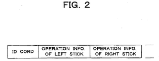
- the control signal has a structure shown in FIG. 2 for example,
- the control signal includes operation information of the left and right sticks 2a and 2b following ID cord by which a corresponding relationship between the controller 2 and the model 3 is judged.
- the operation information includes both information for judging the operation direction from the neutral position of each of the sticks 2a and 2b, and information for judging the number of operation steps from the neutral position.
- the number of operation steps of each of the sticks 2a and 2b is eight, wherein the neutral position of each of the sticks 2a and 2b is defined as 0, the maximum operation step of each stick is defined as 8, and the eight operation steps are located on each of the both sides of the neutral positions.
- the carrier wave onto which the control signal is superposed may be infrared rays or radio wave.
- the model 3 includes a chassis 4 and a cover 5 for covering the chassis 4.
- the cover 5 has an appearance which is modeled after a two-leg-walking type organism or machine.
- a front surface of the cover 5 is directed toward the arrow F in FIG. 1.
- a running device 6 is mounted on the chassis 4.
- the running device 6 includes a pair of motors 7, a pair of wheels 8 disposed left and right front ends of the chassis 4, and a pair of power transmitting mechanisms 9 for transmitting powers of the motors 7 to the wheels 8 independently.
- the chassis 4 is provided at its rear end with a support portion 10 which supports a rear end of the model 3.
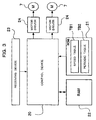
- FIG. 3 shows a structure of a control system for allowing the model 3 to run.
- the model 3 includes a control device 20 comprising a microcomputer, a ROM 21 and a RAM 22 which function as main memories of the control device 20, a receiving device 23 which receives a control signal sent from the controller 2 and converts the control signal into a signal that can be read by the control device 20, and a pair of motor drivers 24 which rotate the motors 7 at speed and in a direction corresponding to a speed signal sent from the control device 20.
- the control device 20 functions as a driving-control device of the running device 6. Interfaces between the hardware are not shown in the drawing.
- a speed table TB1 and a periodic table TB2 are stored in the ROM 21.
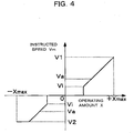
- the speed table TB1 an operating amount X of the left stick 2a and instructed speed Vm of the motor 7 are described as data in association with each other as shown in FIG. 4 for example.
- Signs (positive and negative signs) of the operating amount X in FIG. 4 show the operating direction of the left stick 2a, the positive sign shows the operating direction (upward in FIG. 1) when the model 3 is moved forward, and the negative sign shows the operating direction (downward in FIG. 1) when the model 3 is moved backward.
- the operating amount X and the instructed speed Vm means absolute values in FIG. 4 unless otherwise specified.
- the instructed speed Vm is held at 0 until the operating amount X reaches a given value in the positive direction (upward in FIG. 1), and if the operating amount X exceeds the given value, the instructed speed Vm proportionally increases in the positive direction in accordance with the increase of the operating amount X. If the operating amount X reaches the maximum value Xmax in the positive direction, the instructed speed Vm reaches the maximum value V1 in the normal direction. On the other hand, the instructed speed Vm is held at 0 until the operating amount X reaches the given value in the negative direction (downward in FIG.
- the instructed speed Vm proportionally increases in the negative direction in accordance with the increase of the operating amount x.
- the instructed speed Vm is fixed to the maximum value V2 (V2 ⁇ V1) in the reverse direction before the operating amount X reaches the maximum value Xmax in the negative direction.
- the instructed speed Vm can be adjusted one step by one step from 0 indicative of a stop state to the maximum value V1.
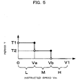
- the instructed speed Vm and period T during which rotation and stop of the motor 7 are repeated are described as data in association with each other as shown in FIG. 5 for example.
- the period T assumes the maximum value T1
- the period T assumes an intermediate value T2 which is somewhat smaller than period T
- the instructed speed Vm is in a speed range H to exceed Vb and be equal to or smaller than the maximum value V1
- the period T becomes 0.
- the upper limit value Va of the speed range L is greater than an initial speed Vi at the moment when the operating amount X exceeds the given value and the instructed speed Vm rises.
- FIG. 6 shows one example of the corresponding relationship between the instructed speed Vm of each motor 7 and period T determined using the tables TB1 and TB2, and control of rotation speed of each motor 7 by the control device 20 (FIG. 3).
- the instructed speed Vm is determined according to the operation information of the left stick 2a included in a control signal sent from the controller 2 by referring to the speed table TB1, and the periodic table TB2 is referred to with respect to the instructed speed Vm to determine the period T.
- the control device 20 controls the motors 7 such that the left and right motors 7 repeat rotation at the instructed speed Vm and stop in a cycle of period T, and the left and right motors 7 rotate alternately.
- the time distributions of the rotation and the stop in the period T are equally set to T/2, the time distributions may be set in a manner other than this.
- the instructed speed Vm is in the speed range H
- the period T becomes 0.
- the control device 20 rotates the left and right motors 7 at the instructed speed Vm simultaneously.
- FIGS. 7A, 7B and 7C show a state in which the model 3 moves forward when the rotations of the motors 7 are controlled in the above-described manner.
- FIG. 7A shows the state in which the instructed speed Vm is in the speed range L
- FIG. 7B shows the state in which the instructed speed Vm is in the speed range M
- FIG. 7C shows the state in which the instructed speed Vm is in the speed range H.
- FIGS. 7A and 7B show a case where the right wheel is rotated first, but it is not always necessary to start driving the right wheel first.
- the model 3 moves forward such that the model 3 alternately turns around the stopped wheel. Therefore, although the running device 6 uses the wheels 8, it is possible to express as if the model 3 walks such that the model 3 alternately projects the two legs while swinging the body of the model 3 laterally.
- the model 3 moves forward while largely and slowly swinging laterally in the speed range L, and the lateral swinging motion is repeated hurriedly and with smaller motion in the speed range M. Due to the combination of the difference between the turning angles and the difference between speeds, the characteristics of the two-leg-walking can be expressed more excellently.
- the alternate rotations of the motors 7 are stopped, the left and right motors 7 are driven at equal speed to move the model 3 straightly in the moving direction.
- the rotation speed of the motor 7 further increases in the speed range H, a state in which the model 3 run fast toward a destination can be expressed, and this is preferable.
- the instructed speed Vm of the motor 7 corresponding to the inner wheel 8 may be reduced with a ratio which is in proportion to the operating amount of he right stick 2b from the neutral position with respect to the instructed speed given by the speed table TB1.
- the period T in this case, for both right and left motors 7, may be determined from the periodic table TB2 based on the instructed speed Vm of the motor 7 corresponding to the outer wheel 8.
- FIG. 8 shows a speed control routine which is carried out by the control device 20 to control the driving operation of the motors 7 as described above.
- the control device 20 repeatedly carries out this speed control routine with given periods.
- the control device 20 first receives a control signal from the receiving device 23 and reads the operation information of the left and right sticks 2a and 2b included in the control signal.
- the control device 20 referrers to the speed table TB1 to obtain the instructed speed Vm which corresponds to the operating amount and the operating direction of the left stick 2a.
- the control device 20 referrers to the periodic table TB2 to obtain the period T which corresponds to the instructed speed Vm.
- step S4 the control device 20 judges whether the period T obtained in the current routine is changed with respect to the period T obtained in step S3 in the last routine. Since the control device 20 makes such a judgment, the control device 20 stores the instructed speed Vm, the period T and the speed signal sent to the each motor 7 determined in every carried out routine as control history in the RAM 22 for a predetermined period.
- step S4 if the period T is not changed, the procedure proceeds to step S5, and the control device 20 judges which one of the pair of motors 7 should be rotated or stopped according to the past control histories until the last history. If the time elapsed after the motor 7 to be rotated and the motor 7 to be stopped were switched last time is smaller than 1/2 of the period T, the motor 7 to be rotated and the motor 7 to be stopped may be determined in the same manner as the last routine. If the elapsed time reached 1/2 of the period T, the motors 7 to be rotated and to be stopped may be switched. If the period T is changed in step S4, the procedure proceeds to step S6 to start switching between the motor 7 to be rotated and the motor 7 to be stopped by a new period T.
- the motor 7 which is previously determined to be driven may be forcibly determined as a motor to be rotated, and the other motor 7 may be forcibly determined as a motor to be stopped, or a motor 7 being rotated at the moment may be determined as a motor to be rotated and the other motor 7 may be determined as a motor to be stopped.
- steps S5 and S6 if the period T is 0, both motors 7 are determined as rotated ones.
- step S7 the control device 20 determines the rotation speed and the rotation direction of the motor 7 to be rotated.
- a rotation speed corresponding to the instructed speed Vm is set, and when the right stick 2b is operated from the neutral position, a rotation speed is obtained by multiplying an instructed speed Vmbya speed reduction ratio (less than 1) of a ratio corresponding to the operating amount of the right stick 2b.
- the rotation direction may be determined according to the operating direction of the left stick 2a.
- step S8 the control device 20 outputs a speed signal indicative of the determined rotation speed and the rotation direction to the motor drivers 24 corresponding to the motor 7 to be rotated, and outputs a speed signal indicative of stop to the motor drivers 24 corresponding to the motor 7 to be stopped. Then, the current routine is completed.
- the running device may include two or more pairs of wheels, In this case, driving operation of at least one pair of wheels may be controlled according to the present invention.
- the controller may determine the instructed speed based on the speed table. In such a case, information for specifying the instructed speed and direction of the motors is added to the control signal from the controller, and the control device on the side of the model may specify the actual rotation speed and the direction of each motor from the instructed speed and the direction.
- the speed range is divided into three stages, i.e., L, M and H in the above embodiment, either one of the speed ranges L and M may be omitted, or the speed range H may be omitted so that the running mode of the model 3 may be changed into two stages.
- the speed range may be divided into more than three stages, and especially the period T may be changed in stepless manner and continuously according to the magnitude of the instructed_speed Vm.
- the running device for a model of the invention can be applied not only to the remote control toy,
- left and right motors may alternately be rotated based on speed instructed according to the program in the same manner as the present invention. That is, the speed may be instructed from outside of the model or inside of the model.
Landscapes
- Engineering & Computer Science (AREA)
- Computer Networks & Wireless Communication (AREA)
- Toys (AREA)
Abstract
In a running device for a model (6) comprising a pair of motors (7), a pair of left and right wheels (8) which are independently driven by the pair of motors (7), and a control device (20) which controls operations of the pair of motors (7) based on instructions concerning speed and direction, the control device (20) controls the pair of motors (7) such that the pair of motors (7) are alternately rotated in an instructed direction when the instructed speed (Vm) is in a low speed range (L, M), and the pair of motors (7) are rotated in the instructed direction simultaneously when the instructed speed is in a high speed range (H) which is higher than the low speed range.
Description
- The present invention relates to a running device for a model which is suitably used for a remote control toy and the like.
- As a running device for a model incorporated in a model of a remote control toy, there are known running devices in which a pair of left and right wheels are driven by separate motors, and a running direction of the model is changed according to a speed difference between the motors (see
Japanese Patent Applications Laid-open Nos.2002-238083 2003-053055 - In the case of the conventional running device, speeds of the motors are simply made different from each other when the running direction of the model is to be changed, and when the model is to be allowed to run straightly, the left and right motors are driven at equal speed. This structure is convenient when the model is modeled after an automobile or the like, but the structure can not sufficiently express a state in which a human or an animal walks on two legs (two-leg-walking, hereinafter).
- Thereupon, it is an object of the present invention to provide a running device capable of realizing a running motion including characteristics of the two-leg-walking by using the structure of driving left and right wheels independently, and a model and a remote control toy using the running device.
- The present invention solves the above problems using the following means:
- The first running device for a model of the invention comprises a pair of motors, a pair of left and right wheels which are independently driven by the pair of motors, and a driving control device which controls operations of the pair of motors respectively based on instructions concerning speed and direction, the driving control device controls the pair of motors such that the pair of motors are alternately rotated in an instructed direction when an instructed speed is in a low speed range, and the pair of motors are rotated in an instructed direction simultaneously when an instructed speed is in a high speed range which is higher than the low speed range.
- According to the first running device for a model, when the speed in the low speed region is instructed, the left and right wheels are alternately rotated so that the model moves in the instructed direction while meandering laterally. Thus, it is possible to express as if the model walks such that the model alternately projects the two legs while swinging the body of the model laterally. On the other hand, when the speed in the high speed region is instructed, such a lateral swinging motion is eliminated, and it is possible to express the state in which the model moves straightly in the instructed direction. In this manner, it is possible to realize the distinctive running including the characteristics of the two-leg-walking as compared with a case in which the speed is simply increased or reduced.
- In the first running device for a model of the invention, if the instructed speed is changed from a low speed side to a high speed side in the low speed range, the driving control device may shorten a period for switching rotations of the motors as compared with the period in the low speed side. As the period for switching rotations of the motors is shorter, the lateral swinging motion of the model is carried out at a higher pitch. Thereby, it is possible to more appropriately express a state in which the model is in a hurry.
- The second model running device comprises a pair of motors, a pair of left and right wheels which are independently driven by the pair of motors, and a driving control device which controls operations of the pair of motors respectively based on instructions concerning speed and direction, the driving control device controls the pair of motors such that the motors are alternately rotated in an instructed direction, and controls such that if an instructed speed is changed from a low speed side to a high speed side, a period for switching rotations of the motors is shortened as compared with the period in the low speed side.
- In the second model running device also, by alternately rotating the left and right wheels, it is possible to express as if the model walks such that the model alternately projects the two legs while swinging the body of the model laterally. Further, if the instructed speed is changed from the low speed side to the high speed side, the period for switching the rotations of the motors becomes shorter than that in the low speed side, and thereby the lateral swinging motion of the model is carried out at higher pitch. Thus, it is possible to express a state in which the model slowly walks while swinging its body laterally in the low speed side, and the model walks at high pitch in the high speed side.
- In each of the running device for a models of the invention, as the instructed speed is higher, the driving control device may increase the rotation speed of the motor which is being driven. By combining the increase and decrease in speed, difference between slow motion and quick motion concerning the movement of the model can be expressed more clearly.
- Further, the running device for a model of the invention can suitably be used for a model which is modeled after a two-leg-walking type organism or machine. If the running device for a model is applied to such a model, the appearance of the model and running characteristics thereof are combined, and it is possible to strongly give the impression that the model is walking in the two-leg-walking manner to users.
- The first remote control toy of the invention includes a controller and a model, the controller generating and sending a control signal corresponding to operation of a user, the model having a running device to be remotely controlled based on the control signal, the running device includes a pair of motors, a pair of left and right wheels which are independently driven by the pair of motors, and a driving control device which controls operations of the pair of motors respectively based on instructions concerning the speed and direction specified according to the control signal, the driving control device controls the pair of motors such that the pair of motors are alternately rotated in an instructed direction when an instructed speed is in a low speed range, and the pair of motors are rotated in an instructed direction simultaneously when an instructed speed is in a high speed range which is higher than the low speed range.
- According to the first remote control toy, since the toy has the first model running device, the manner of moving the model can be changed between the case in which the low speed is instructed and the case in which the high speed is instructed. Thus, it is possible to realize the distinctive running including the characteristics of the two-leg-walking as compared with a case in which the speed is simply increased or reduced.
- In the first remote control toy of the invention, if the instructed speed is changed from a low speed side to a high speed side in the low speed range, the driving control device may shorten a period for switching rotations of the motors as compared with the period in the low speed side.
- The second remote control toy of the invention includes a controller and a model, the controller generating and sending a control signal corresponding to operation of a user, the model having a running device to be remotely controlled based on the control signal, the running device includes a pair of motors, a pair of left and right wheels which are independently driven by the pair of motors, and a driving control device which controls operations of the pair of motors respectively based on instructions concerning the speed and direction specified according to the control signal, the driving control device controls the pair of motors such that the motors are alternately rotated in an instructed direction, and controls such that if an instructed speed is changed from a low speed side to a high speed side, a period for switching rotations of the motors is shortened as compared with the period in the low speed side.
- According to the second remote control toy, since the toy includes the second model running device, the period of the swinging motion of the model in the high speed side is set shorter than that in the low speed side, and it is possible to express a state in which the model slowly walks while swinging its body laterally in the low speed side, and the model walks at high pitch in the high speed side.
- In the remote control toy of the invention, as the instructed speed is higher, the driving control device may increase the rotation speed of the motor being driven, and the model may be modeled after a two-leg-walking type organism or machine. Merits obtained from these structure are as explained in the explanation of the running device for a model.
- As explained above, according to the present invention, a state in which the left and right wheels are alternately rotated and a state in which the wheels are rotated simultaneously are used properly, or the period during which the rotations of the left and right wheels are switched is changed. Thus, it is possible to express as if the model walks such that the model alternately projects the two legs while swinging the body of the modellaterally, and the moving manner can be changed according to the instructed speed. Therefore, the model can obtain the running motion which is similar to the two-leg-walking by utilizing the structure in which the left and right wheels are independently driven.
-
- FIG. 1 is a schematic view of a remote control toy to which the present invention is applied;
- FIG. 2 shows one example of a control signal sent from a controller;
- FIG. 3 is a block diagram of a control system for allowing a model shown in FIG. 1 to run;
- FIG. 4 is a graph showing contents of a speed table which is referred to by the control system shown in FIG. 3;
- FIG. 5 is a graph showing contents of a periodic table which is referred to by the control system shown in FIG. 3;
- FIG. 6 shows one example of a corresponding relationship between instructed speed and period obtained by referring to the speed table and the periodic table, and rotation speeds of motors;
- FIG. 7A shows a state in which the model moves forward when a control device controls the rotation of the motor in a speed range L;
- FIG. 7B shows a state in which the model moves forward when the control device controls the rotation of the motor in a speed range M;
- FIG. 7C shows a state in which the model moves forward when a control device controls the rotation of the motor in a speed range H; and
- FIG. 8 is a flowchart showing a speed control routine which is carried out by the control device to control the driving operation of the motor.
- FIG. 1 shows one mode of a running device for a model of the present invention, which is applied to a
remote control toy 1. Theremote control toy 1 includes acontroller 2 and amodel 3. Thecontroller 2 includes aleft stick 2a and aright stick 2b as operation members which are operated by a user to allow themodel 3 to run. Theleft stick 2a is operated in the vertical direction in FIG. 1 from a predetermined neutral position for instructing a running direction and speed of themodel 3. Theright stick 2b is operated in the lateral direction in FIG. 1 from the predetermined neutral position for laterally changing the moving direction of themodel 3. Thecontroller 2 includes, therein, a control device (not shown) comprising amicrocomputer. The control device sends a control signal for judging operation states of thesticks right sticks controller 2 and themodel 3 is judged. The operation information includes both information for judging the operation direction from the neutral position of each of thesticks sticks sticks - Referring back to FIG. 1, the
model 3 includes achassis 4 and acover 5 for covering thechassis 4. Thecover 5 has an appearance which is modeled after a two-leg-walking type organism or machine. A front surface of thecover 5 is directed toward the arrow F in FIG. 1. A running device 6 is mounted on thechassis 4. The running device 6 includes a pair ofmotors 7, a pair ofwheels 8 disposed left and right front ends of thechassis 4, and a pair of power transmitting mechanisms 9 for transmitting powers of themotors 7 to thewheels 8 independently. Thechassis 4 is provided at its rear end with asupport portion 10 which supports a rear end of themodel 3. - FIG. 3 shows a structure of a control system for allowing the
model 3 to run. Themodel 3 includes acontrol device 20 comprising a microcomputer, aROM 21 and aRAM 22 which function as main memories of thecontrol device 20, a receivingdevice 23 which receives a control signal sent from thecontroller 2 and converts the control signal into a signal that can be read by thecontrol device 20, and a pair ofmotor drivers 24 which rotate themotors 7 at speed and in a direction corresponding to a speed signal sent from thecontrol device 20. Thecontrol device 20 functions as a driving-control device of the running device 6. Interfaces between the hardware are not shown in the drawing. - In order to determine the rotation speed and the rotation direction of the
motor 7 based on the control signal sent from thecontroller 2, a speed table TB1 and a periodic table TB2 are stored in theROM 21. In the speed table TB1, an operating amount X of theleft stick 2a and instructed speed Vm of themotor 7 are described as data in association with each other as shown in FIG. 4 for example. Signs (positive and negative signs) of the operating amount X in FIG. 4 show the operating direction of theleft stick 2a, the positive sign shows the operating direction (upward in FIG. 1) when themodel 3 is moved forward, and the negative sign shows the operating direction (downward in FIG. 1) when themodel 3 is moved backward. Signs (positive and negative signs) of the instructed speed Vm in FIG. 4 show the rotation direction of themotor 7, the positive sign shows the rotation direction (normal direction, hereinafter) when themodel 3 is moved forward, and the negative sign shows the rotation direction (reverse direction, hereinafter) when themodel 3 is moved backward. In the following description, the operating amount X and the instructed speed Vm means absolute values in FIG. 4 unless otherwise specified. - In the example shown in FIG. 4, the instructed speed Vm is held at 0 until the operating amount X reaches a given value in the positive direction (upward in FIG. 1), and if the operating amount X exceeds the given value, the instructed speed Vm proportionally increases in the positive direction in accordance with the increase of the operating amount X. If the operating amount X reaches the maximum value Xmax in the positive direction, the instructed speed Vm reaches the maximum value V1 in the normal direction. On the other hand, the instructed speed Vm is held at 0 until the operating amount X reaches the given value in the negative direction (downward in FIG. 1), and if the operating amount X exceeds the given value, the instructed speed Vm proportionally increases in the negative direction in accordance with the increase of the operating amount x. Here, the instructed speed Vm is fixed to the maximum value V2 (V2<V1) in the reverse direction before the operating amount X reaches the maximum value Xmax in the negative direction. The instructed speed Vm can be adjusted one step by one step from 0 indicative of a stop state to the maximum value V1.
- On the other hand, in the periodic table TB2, the instructed speed Vm and period T during which rotation and stop of the
motor 7 are repeated are described as data in association with each other as shown in FIG. 5 for example. In this example, when the instructed speed Vm is in a speed range L to be greater than 0 and equal to or smaller than Va, the period T assumes the maximum value T1, and when the instructed speed Vm is in a speed range M to exceed Va and be equal to or smaller than Vb, the period T assumes an intermediate value T2 which is somewhat smaller than period T, and when the instructed speed Vm is in a speed range H to exceed Vb and be equal to or smaller than the maximum value V1, the period T becomes 0. In the relationship with FIG. 4, the upper limit value Va of the speed range L is greater than an initial speed Vi at the moment when the operating amount X exceeds the given value and the instructed speed Vm rises. - FIG. 6 shows one example of the corresponding relationship between the instructed speed Vm of each
motor 7 and period T determined using the tables TB1 and TB2, and control of rotation speed of eachmotor 7 by the control device 20 (FIG. 3). In FIG. 6, it is assumed that theleft stick 2a of thecontroller 2 is operated from the neutral position by a given amount, and theright stick 2b is held at the neutral position. In this case, the instructed speed Vm is determined according to the operation information of theleft stick 2a included in a control signal sent from thecontroller 2 by referring to the speed table TB1, and the periodic table TB2 is referred to with respect to the instructed speed Vm to determine the period T. Thus, thecontrol device 20 controls themotors 7 such that the left andright motors 7 repeat rotation at the instructed speed Vm and stop in a cycle of period T, and the left andright motors 7 rotate alternately. Although the time distributions of the rotation and the stop in the period T are equally set to T/2, the time distributions may be set in a manner other than this. When the instructed speed Vm is in the speed range H, the period T becomes 0. In this case, thecontrol device 20 rotates the left andright motors 7 at the instructed speed Vm simultaneously. - FIGS. 7A, 7B and 7C show a state in which the
model 3 moves forward when the rotations of themotors 7 are controlled in the above-described manner. FIG. 7A shows the state in which the instructed speed Vm is in the speed range L, FIG. 7B shows the state in which the instructed speed Vm is in the speed range M, and FIG. 7C shows the state in which the instructed speed Vm is in the speed range H. FIGS. 7A and 7B show a case where the right wheel is rotated first, but it is not always necessary to start driving the right wheel first. As shown in FIGS. 7A and 7B, when themotors 7 are rotated alternately, themodel 3 moves forward such that themodel 3 alternately turns around the stopped wheel. Therefore, although the running device 6 uses thewheels 8, it is possible to express as if themodel 3 walks such that themodel 3 alternately projects the two legs while swinging the body of themodel 3 laterally. - As apparent from comparison between FIGS. 7A and 7B, if the instructed speed Vm increases and the speed range is shifted from the speed range L to the speed range M, the period T is reduced from T1 to T2, the swinging motion pitch of the
model 3 in the lateral direction becomes shorter, and the angle through which themodel 3 turns in a half period (T/2) is reduced. Therefore, the lateral swinging motion of themodel 3 becomes small, and it is possible to express as if themodel 3 is in a hurry as compared with the speed range L. - Since the rotation speed of the
motor 7 in the speed range L is lower than that in the speed range M, themodel 3 moves forward while largely and slowly swinging laterally in the speed range L, and the lateral swinging motion is repeated hurriedly and with smaller motion in the speed range M. Due to the combination of the difference between the turning angles and the difference between speeds, the characteristics of the two-leg-walking can be expressed more excellently. - If the instructed speed Vm increases to the speed range H, the alternate rotations of the
motors 7 are stopped, the left andright motors 7 are driven at equal speed to move themodel 3 straightly in the moving direction. Thus, it is possible to express a state in which themodel 3 moves straightly toward a destination. Since the rotation speed of themotor 7 further increases in the speed range H, a state in which themodel 3 run fast toward a destination can be expressed, and this is preferable. - Although the
right stick 2b is held at the neutral position and themodel 3 moves straightly in the above example, when theright stick 2b is operated in such a manner, the instructed speed Vm of themotor 7 corresponding to theinner wheel 8 may be reduced with a ratio which is in proportion to the operating amount of he right stick 2b from the neutral position with respect to the instructed speed given by the speed table TB1. The period T in this case, for both right and leftmotors 7, may be determined from the periodic table TB2 based on the instructed speed Vm of themotor 7 corresponding to theouter wheel 8. - FIG. 8 shows a speed control routine which is carried out by the
control device 20 to control the driving operation of themotors 7 as described above. Thecontrol device 20 repeatedly carries out this speed control routine with given periods. In this speed control routine, in step S1, thecontrol device 20 first receives a control signal from the receivingdevice 23 and reads the operation information of the left andright sticks control device 20 referrers to the speed table TB1 to obtain the instructed speed Vm which corresponds to the operating amount and the operating direction of theleft stick 2a. In step S3, thecontrol device 20 referrers to the periodic table TB2 to obtain the period T which corresponds to the instructed speed Vm. - Further, in step S4, the
control device 20 judges whether the period T obtained in the current routine is changed with respect to the period T obtained in step S3 in the last routine. Since thecontrol device 20 makes such a judgment, thecontrol device 20 stores the instructed speed Vm, the period T and the speed signal sent to the eachmotor 7 determined in every carried out routine as control history in theRAM 22 for a predetermined period. - In step S4, if the period T is not changed, the procedure proceeds to step S5, and the
control device 20 judges which one of the pair ofmotors 7 should be rotated or stopped according to the past control histories until the last history. If the time elapsed after themotor 7 to be rotated and themotor 7 to be stopped were switched last time is smaller than 1/2 of the period T, themotor 7 to be rotated and themotor 7 to be stopped may be determined in the same manner as the last routine. If the elapsed time reached 1/2 of the period T, themotors 7 to be rotated and to be stopped may be switched. If the period T is changed in step S4, the procedure proceeds to step S6 to start switching between themotor 7 to be rotated and themotor 7 to be stopped by a new period T. In this case, themotor 7 which is previously determined to be driven may be forcibly determined as a motor to be rotated, and theother motor 7 may be forcibly determined as a motor to be stopped, or amotor 7 being rotated at the moment may be determined as a motor to be rotated and theother motor 7 may be determined as a motor to be stopped. In steps S5 and S6, if the period T is 0, bothmotors 7 are determined as rotated ones. - After a
motor 7 to be rotated and amotor 7 to be stopped are determined in steps S5 and S6, the procedure proceeds to step S7, and thecontrol device 20 determines the rotation speed and the rotation direction of themotor 7 to be rotated. Here, when theright stick 2b is in the neutral position, a rotation speed corresponding to the instructed speed Vm is set, and when theright stick 2b is operated from the neutral position, a rotation speed is obtained by multiplying an instructed speed Vmbya speed reduction ratio (less than 1) of a ratio corresponding to the operating amount of theright stick 2b. The rotation direction may be determined according to the operating direction of theleft stick 2a. After the rotation speed and the direction are determined in step S7, thecontrol device 20 makes the procedure proceed to step S8. In step S8, thecontrol device 20 outputs a speed signal indicative of the determined rotation speed and the rotation direction to themotor drivers 24 corresponding to themotor 7 to be rotated, and outputs a speed signal indicative of stop to themotor drivers 24 corresponding to themotor 7 to be stopped. Then, the current routine is completed. - The present invention is not limited to the above modes, and can be carried out in various modes. For example, the running device may include two or more pairs of wheels, In this case, driving operation of at least one pair of wheels may be controlled according to the present invention. The controller may determine the instructed speed based on the speed table. In such a case, information for specifying the instructed speed and direction of the motors is added to the control signal from the controller, and the control device on the side of the model may specify the actual rotation speed and the direction of each motor from the instructed speed and the direction. Although the speed range is divided into three stages, i.e., L, M and H in the above embodiment, either one of the speed ranges L and M may be omitted, or the speed range H may be omitted so that the running mode of the
model 3 may be changed into two stages. On the contrary, the speed range may be divided into more than three stages, and especially the period T may be changed in stepless manner and continuously according to the magnitude of the instructed_speed Vm. - The running device for a model of the invention can be applied not only to the remote control toy, For example, in the case of a self-propelled toy which runs according to a previously written program, left and right motors may alternately be rotated based on speed instructed according to the program in the same manner as the present invention. That is, the speed may be instructed from outside of the model or inside of the model.
Claims (10)
- A running device for a model comprising a pair of motors, a pair of left and right wheels which are independently driven by the pair of motors, and a driving control device which controls operations of the pair of motors respectively based on instructions concerning speed and direction, wherein
the driving control device controls the pair of motors such that the pair of motors are alternately rotated in an instructed direction when an instructed speed is in a low speed range, and the pair of motors are rotated in an instructed direction simultaneously when an instructed speed is in a high speed range which is higher than the low speed range. - The running device for a model according to claim 1, wherein if the instructed speed is changed from a low speed side to a high speed side in the low speed range, the driving control device shortens a period for switching rotations of the motors compared with the period in the low speed side.
- A running device for a model comprising a pair of motors, a pair of left and right wheels which are independently driven by the pair of motors, and a driving control device which controls operations of the pair of motors respectively based on instructions concerning speed and direction, wherein
the driving control device controls the pair of motors such that the motors are alternately rotated in an instructed direction, and controls such that if an instructed speed is changed from a low speed side to a high speed side, a period for switching rotations of the motors is shortened as compared with the period in the low speed side. - The running device for a model according to any one of claims 1 to 3, wherein as the instructed speed is higher, the driving control device increases the rotation speed of the motor being driven.
- A model having the running device for a model according to any one of claims 1 to 4, wherein the model is modeled after a two-leg-walking type organism or machine.
- A remote control toy including a controller and a model, the controller generating and sending a control signal corresponding to operation of a user, the model having a running device to be controlled remotely based on the control signal, wherein
the running device includes a pair of motors, a pair of left and right wheels which are independently driven by the pair of motors, and a driving control device which controls operations of the pair of motors respectively based on instructions concerning the speed and direction specified according to the control signal,
the driving control device controls the pair of motors such that the pair of motors are alternately rotated in an instructed direction when an instructed speed is in a low speed range, and the pair of motors are rotated in an instructed direction simultaneously when an instructed speed is in a high speed range which is higher than the low speed range. - The remote control toy according to claim 1, wherein if the instructed speed is changed from a low speed side to a high speed side in the low speed range, the driving control device shortens a period for switching rotations of the motors as compared with the period in the low speed side.
- A remote control toy including a controller and a model, the controller generating and sending a control signal corresponding to operation of a user, the model having a running device to be controlled remotely based on the control signal, wherein
the running device includes a pair of motors, a pair of left and right wheels which are independently driven by the pair of motors, and a driving control device which controls operations of the pair of motors respectively based on instructions concerning the speed and direction specified according to the control signal,
the driving control device controls the pair of motors such that the motors are alternately rotated in an instructed direction, and controls such that if an instructed speed is changed from a low speed side to a high speed side, a period for switching rotations of the motors are switched is shortened as compared with the period in the low speed side. - The remote control toy according to any one of claims 6 to 8, wherein as the instructed speed is higher, the driving control device increases the rotation speed of the motor being driven.
- The remote control toy according to any one of claims 6 to 9, wherein the model is modeled after a two-leg-walking type organism or machine.
Applications Claiming Priority (2)
| Application Number | Priority Date | Filing Date | Title |
|---|---|---|---|
| JP2003282128 | 2003-07-29 | ||
| PCT/JP2004/010984 WO2005009572A1 (en) | 2003-07-29 | 2004-07-26 | Model traveling device, model having such traveling device, and remote-controlled toy |
Publications (2)
| Publication Number | Publication Date |
|---|---|
| EP1712262A1 true EP1712262A1 (en) | 2006-10-18 |
| EP1712262A4 EP1712262A4 (en) | 2007-08-15 |
Family
ID=34100993
Family Applications (1)
| Application Number | Title | Priority Date | Filing Date |
|---|---|---|---|
| EP04748143A Withdrawn EP1712262A4 (en) | 2003-07-29 | 2004-07-26 | Model traveling device, model having such traveling device, and remote-controlled toy |
Country Status (6)
| Country | Link |
|---|---|
| US (1) | US7479055B2 (en) |
| EP (1) | EP1712262A4 (en) |
| JP (1) | JP4503533B2 (en) |
| KR (1) | KR100781004B1 (en) |
| CN (1) | CN1697671B (en) |
| WO (1) | WO2005009572A1 (en) |
Families Citing this family (8)
| Publication number | Priority date | Publication date | Assignee | Title |
|---|---|---|---|---|
| US7789728B2 (en) * | 2005-08-31 | 2010-09-07 | Jakks Pacific, Inc. | Adapter for motorizing a non-motorized toy vehicle |
| US9411944B2 (en) * | 2006-11-15 | 2016-08-09 | Cfph, Llc | Biometric access sensitivity |
| US20080146117A1 (en) * | 2006-11-27 | 2008-06-19 | Tiburzi Davis R | Directional Vibrating Motion Base |
| GB0901541D0 (en) * | 2009-01-30 | 2009-03-11 | China Ind Ltd | Toy snake |
| CN102743877A (en) * | 2011-04-19 | 2012-10-24 | 徐菲 | Electronic interaction toy device and method |
| US8764511B2 (en) * | 2011-04-29 | 2014-07-01 | Mattel, Inc. | Toy vehicle |
| US10094669B2 (en) * | 2015-10-29 | 2018-10-09 | Horizon Hobby, LLC | Systems and methods for inertially-instituted binding of a RC vehicle |
| CN111381572A (en) * | 2018-12-27 | 2020-07-07 | 驭势科技(北京)有限公司 | Vehicle control method, vehicle-mounted control device and vehicle remote control system |
Family Cites Families (11)
| Publication number | Priority date | Publication date | Assignee | Title |
|---|---|---|---|---|
| US4213270A (en) * | 1978-08-07 | 1980-07-22 | Nobuo Oda | Radio controlled wheel toy |
| US4355482A (en) * | 1980-11-26 | 1982-10-26 | Mattel, Inc. | Skating doll |
| JPH0443268Y2 (en) * | 1985-09-10 | 1992-10-13 | ||
| US5135427A (en) * | 1991-01-22 | 1992-08-04 | Tyco Industries, Inc. | Caterpillar-type vehicle toy |
| US5667420A (en) * | 1994-01-25 | 1997-09-16 | Tyco Industries, Inc. | Rotating vehicle toy |
| US6024627A (en) * | 1997-08-19 | 2000-02-15 | Tilbor; Neil | Toy vehicle with gyroscopic action rear wheels |
| JPH11333150A (en) * | 1998-05-29 | 1999-12-07 | Canon Inc | How to turn |
| JP3451073B2 (en) * | 2001-02-09 | 2003-09-29 | コナミ株式会社 | Remote control system, transmitter used therefor, program and storage medium for remote control system |
| CN2492278Y (en) * | 2001-05-11 | 2002-05-22 | 哈尔滨海尔哈工大机器人技术有限公司 | Moving mechanism of robot toy |
| JP4786854B2 (en) * | 2001-06-06 | 2011-10-05 | 株式会社コナミデジタルエンタテインメント | Toy system |
| JP3432810B2 (en) * | 2001-06-06 | 2003-08-04 | コナミ株式会社 | Toy system |
-
2004
- 2004-07-26 JP JP2005512103A patent/JP4503533B2/en not_active Expired - Fee Related
- 2004-07-26 EP EP04748143A patent/EP1712262A4/en not_active Withdrawn
- 2004-07-26 KR KR1020057023482A patent/KR100781004B1/en not_active Expired - Fee Related
- 2004-07-26 US US10/510,187 patent/US7479055B2/en not_active Expired - Lifetime
- 2004-07-26 WO PCT/JP2004/010984 patent/WO2005009572A1/en not_active Ceased
- 2004-07-26 CN CN200480000483XA patent/CN1697671B/en not_active Expired - Lifetime
Also Published As
| Publication number | Publication date |
|---|---|
| KR100781004B1 (en) | 2007-11-29 |
| CN1697671A (en) | 2005-11-16 |
| JP4503533B2 (en) | 2010-07-14 |
| US20060154563A1 (en) | 2006-07-13 |
| CN1697671B (en) | 2010-10-06 |
| KR20060018244A (en) | 2006-02-28 |
| WO2005009572A1 (en) | 2005-02-03 |
| JPWO2005009572A1 (en) | 2006-09-07 |
| US7479055B2 (en) | 2009-01-20 |
| EP1712262A4 (en) | 2007-08-15 |
Similar Documents
| Publication | Publication Date | Title |
|---|---|---|
| JP2957881B2 (en) | Biped robot | |
| US5088955A (en) | Sound effect device for radio controllable toy vehicle | |
| CN102018396B (en) | Swing control device and method for baby products | |
| US7479055B2 (en) | Running device for model, and model and remote control toy having the running device | |
| WO2002040227A1 (en) | Remote controller of biped robot | |
| JPS61162969A (en) | Automatic erectable running toy | |
| CN113848968B (en) | Gait adjustment method, multi-legged robot, and computer-readable storage medium | |
| EP1264624A2 (en) | Toy system | |
| US6758719B1 (en) | Radio controlled vehicle with a system for selectively lifting portions of the vehicle frame | |
| KR100572684B1 (en) | Biped walking robot driving method and apparatus for transition to driving mode | |
| KR20020066020A (en) | Unmanned Electric Bicycle using a Gyro | |
| CN101162887A (en) | Motor controller | |
| JP2005066810A (en) | Joint device for robot | |
| CN108803414B (en) | Rolling vehicle control system and method | |
| KR102392930B1 (en) | Biped walking device using two independent rotating motors, control method for bipedal walking | |
| US7563151B2 (en) | Toy vehicle with big wheel | |
| JP2004129957A (en) | Bipedal toy | |
| CN116215722B (en) | Electric vehicle and control method thereof | |
| KR20030092762A (en) | Frame robot and a device for programming a control program thereof with icons | |
| JP2008100287A (en) | Robot system | |
| JP3881897B2 (en) | Toy system and its controller | |
| CN215895518U (en) | Artificial intelligence vision people flow thermodynamic diagram analytic system based on unmanned aerial vehicle | |
| JP2004154183A (en) | Biped Remote Control Toy | |
| CN109011638B (en) | Remote-controllable assembled building block component and assembled building block system | |
| CN210109609U (en) | Self-constructed wheel type robot |
Legal Events
| Date | Code | Title | Description |
|---|---|---|---|
| PUAI | Public reference made under article 153(3) epc to a published international application that has entered the european phase |
Free format text: ORIGINAL CODE: 0009012 |
|
| 17P | Request for examination filed |
Effective date: 20040927 |
|
| AK | Designated contracting states |
Kind code of ref document: A1 Designated state(s): DE ES FR GB IT |
|
| DAX | Request for extension of the european patent (deleted) | ||
| RBV | Designated contracting states (corrected) |
Designated state(s): DE ES FR GB IT |
|
| A4 | Supplementary search report drawn up and despatched |
Effective date: 20070717 |
|
| RAP1 | Party data changed (applicant data changed or rights of an application transferred) |
Owner name: KONAMI DIGITAL ENTERTAINMENT CO., LTD. |
|
| STAA | Information on the status of an ep patent application or granted ep patent |
Free format text: STATUS: THE APPLICATION IS DEEMED TO BE WITHDRAWN |
|
| 18D | Application deemed to be withdrawn |
Effective date: 20110201 |